Embed Size (px)
Citation preview
ISO/TC 25/WG 9 N 2
ISO/TC 25/WG 9Classification: Grey cast irons
Email of secretary: Convenorship: ANSI (United States)
25-0-9 N002 Comparison-of-ISO185-and-EN1561 2015-08-31
Document type: Other committee document
Date of document: 2015-08-31
Expected action: INFO
Background:
Committee URL: http://isotc.iso.org/livelink/livelink/open/tc25wg9
Date: 2015-08-31
Comparison of ISO 185:2005 and EN 1561:2011
Following is an indication of where EN 1561:2011 differs from ISO 185:2005. So far as the convener is aware, the EN standard was based on ISO 185, but differs in a number of respects. Some of the significant differences are indicated in the mark-up of ISO 185. This document is intended as the starting point for discussion among TC 25/WG 9 experts regarding a possible NWI to revise ISO 185.
ISO/TC 25//WG 9 N 002

— This page intentionally left blank —
ISO/WD 185:2015
ISO TC 25/WG 9
Secretariat: ANSI
Gray cast irons — Classification and specification
Preliminary WD stage
ISO/WD 185:2015
2 © ISO 2015 – All rights reserved
© ISO 2013
All rights reserved. Unless otherwise specified, no part of this publication may be reproduced or utilized otherwise in any form or by any means, electronic or mechanical, including photocopying, or posting on the internet or an intranet, without prior written permission. Permission can be requested from either ISO at the address below or ISO's member body in the country of the requester.
ISO Copyright Office CP 56 - CH-1211 Geneva 20 Phone: + 41 22 749 01 11 Fax: + 41 22 749 09 47 Email: [email protected] Website: www.iso.org
Published in Switzerland.

ISO/WD 185:2015
© ISO 2015 – All rights reserved 3
Foreword
A boiler plate text will be inserted by ISO CS from DIS onwards.
List here any additional parts in the series.
List here the changes if this document is a revision.
ISO/WD 185:2015
4 © ISO 2015 – All rights reserved
Introduction
A paragraph.
ISO/WD 185:2015
© ISO 2015 – All rights reserved 5
Introductory element — Main element — Part #: Part title
1 Scope
This International Standard specifies the properties of unalloyed and low-alloyed grey cast irons used for castings which have been manufactured in sand moulds or in moulds with comparable thermal behaviour.
This International Standard specifies the characterizing properties of grey cast iron by either
a) the tensile strength of separately cast samples, or if agreed by the manufacturer and the purchaser, of cast-on samples or samples cut from a casting (see Table 1), or
b) if agreed between the manufacturer and the purchaser, the hardness of the material measured on castings (see Table 2) or on a cast-on knob.
If agreed by the manufacturer and the purchaser, the combination of both tensile strength from option a) and hardness from option b) may be specified. When specifying a combination of tensile strength and hardness, it is recommended to consult the information in Annex B.
This International Standard does not apply to grey cast irons used for pipes and pipe fittings and continuous cast products.
This International Standard specifies eight grades of grey cast iron according to the tensile strength (see Table 1) and six grades of grey cast iron according to the Brinell hardness (see Table 2).
2 Normative references
The following documents, in whole or in part, are normatively referenced in this document and are indispensable for its application. For dated references, only the edition cited applies. For undated references, the latest edition of the referenced document (including any amendments) applies.
ISO 945-1, Cast iron — Designation of microstructure of graphite
ISO 6506-1, Metallic materials — Brinell hardness test — Part 1: Test method
ISO 6892, Metallic materials — Tensile testing at ambient temperature
ISO/TR 15931, Designation system for cast irons and pig irons
3 Terms and definitions
For the purposes of ISO 185, the following terms and definitions apply.
3.1 grey cast iron cast material, iron and carbon based, carbon being present mainly in the form of flake (lamellar) graphite particles
NOTE 1 Grey cast iron is also known as flake graphite cast iron, and less commonly as lamellar graphite cast iron.
ISO/WD 185:2015
6 © ISO 2015 – All rights reserved
NOTE 2 Graphite form, distribution and size are specified in ISO 945.
3.2 relevant wall thickness section of the casting, agreed between the manufacturer and the purchaser, to which the determined mechanical properties apply
4 Designation
The material shall be designated as given in either Table 1 or Table 2. The designation system is given in ISO/TR 15931.
5 Order information
The following information shall be supplied by the purchaser:
a) the complete designation of the material;
b) any special requirements which have to be agreed between the manufacturer and the purchaser.
All agreements between the manufacturer and the purchaser shall be made by the time of acceptance of the order.
6 Manufacture
The method of producing grey cast iron and its chemical composition shall be left to the discretion of the manufacturer, who shall ensure that the requirements of this International Standard are met for the material grade specified in the order.
NOTE For grey cast irons to be used in special applications, the chemical composition and heat treatment may be the subject of an agreement between the manufacturer and the purchaser.
7 Requirements
7.1 Mechanical properties
The order shall specify, in an unambiguous manner, whether the tensile strength measured on separately cast samples, or the Brinell hardness measured on the casting, is the characterizing property. If it does not do so, then the manufacturer shall characterize the material according to tensile strength.
7.2 Tensile properties
7.2.1 Test pieces machined from separately cast samples
The tensile properties of the eight grades of grey cast iron specified by tensile strength, when measured in accordance with 9.1 using test pieces machined from separately cast samples, shall be in accordance with the requirements of Table 1.
The number in position 3 of the designation is the minimum tensile strength of the grade. The maximum tensile strength of the grade is the minimum value plus 100 N/mm2.
7.2.2 Test pieces machined from cast-on samples
The tensile properties of test pieces machined from cast-on samples, for the eight grades of grey cast iron defined by tensile strength, shall be in accordance with the requirements of Table 1.
ISO/WD 185:2015
© ISO 2015 – All rights reserved 7
7.2.3 Test pieces cut from a casting
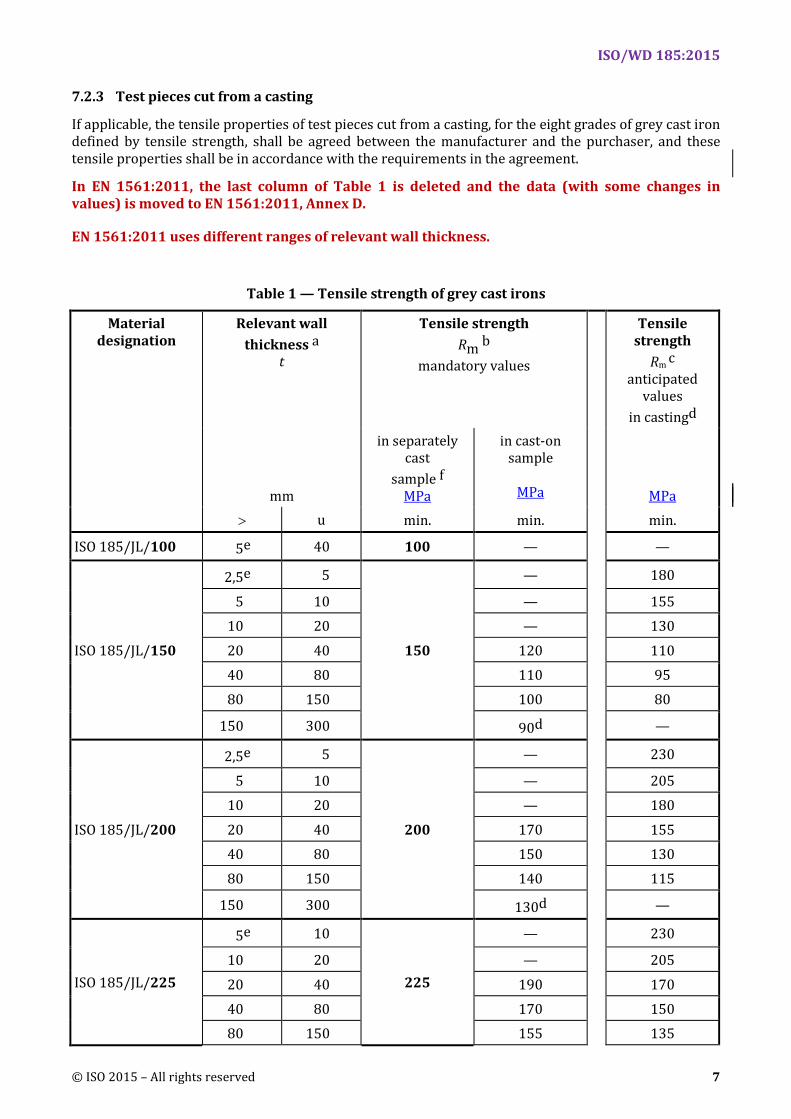
If applicable, the tensile properties of test pieces cut from a casting, for the eight grades of grey cast iron defined by tensile strength, shall be agreed between the manufacturer and the purchaser, and these tensile properties shall be in accordance with the requirements in the agreement.
In EN 1561:2011, the last column of Table 1 is deleted and the data (with some changes in values) is moved to EN 1561:2011, Annex D.
EN 1561:2011 uses different ranges of relevant wall thickness.
Table 1 — Tensile strength of grey cast irons
Material designation
Relevant wall thickness a
t
Tensile strength Rm b
mandatory values
Tensile strength
Rm c anticipated
values in castingd
mm
in separately cast
sample f MPa
in cast-on sample
MPa MPa
> u min. min. min.
ISO 185/JL/100 5e 40 100 — —
ISO 185/JL/150
2,5e 5
150
— 180
5 10 — 155 10 20 — 130
20 40 120 110 40 80 110 95 80 150 100 80
150 300 90d —
ISO 185/JL/200
2,5e 5
200
— 230
5 10 — 205 10 20 — 180
20 40 170 155 40 80 150 130 80 150 140 115
150 300 130d —
ISO 185/JL/225
5e 10
225
— 230
10 20 — 205
20 40 190 170 40 80 170 150 80 150 155 135
ISO/WD 185:2015
8 © ISO 2015 – All rights reserved
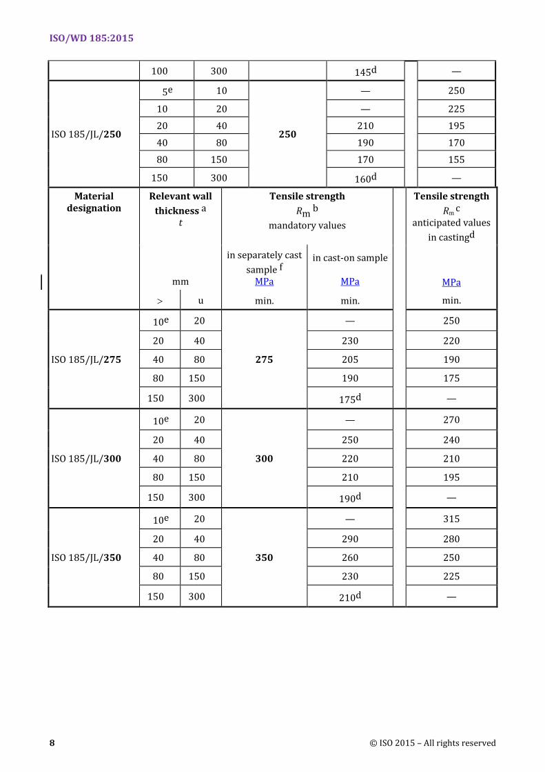
100 300 145d —
ISO 185/JL/250
5e 10
250
—
250
10 20 — 225 20 40 210 195
40 80 190 170 80 150 170 155
150 300 160d —
Material designation
Relevant wall thickness a
t
Tensile strength Rm b
mandatory values
Tensile strength Rm c
anticipated values in castingd
mm
in separately cast sample f
MPa
in cast-on sample
MPa MPa
> u min. min. min.
ISO 185/JL/275
10e 20
275
—
250
20 40 230 220
40 80 205 190
80 150 190 175
150 300 175d —
ISO 185/JL/300
10e 20
300
—
270
20 40 250 240
40 80 220 210
80 150 210 195
150 300 190d —
ISO 185/JL/350
10e 20
350
— 315
20 40 290 280
40 80 260 250
80 150 230 225
150 300 210d —
ISO/WD 185:2015
© ISO 2015 – All rights reserved 9
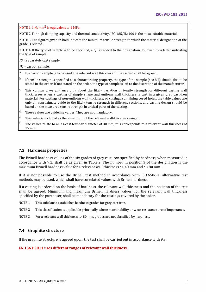
NOTE 1 1 N/mm2 is equivalent to 1 MPa.
NOTE 2 For high damping capacity and thermal conductivity, ISO 185/JL/100 is the most suitable material.
NOTE 3 The figures given in bold indicate the minimum tensile strength to which the material designation of the grade is related.
NOTE 4 If the type of sample is to be specified, a "/" is added to the designation, followed by a letter indicating the type of sample:
/S = separately cast sample;
/U = cast-on sample. a If a cast-on sample is to be used, the relevant wall thickness of the casting shall be agreed. b If tensile strength is specified as a characterizing property, the type of the sample (see 8.2) should also to be
stated in the order. If not stated on the order, the type of sample is left to the discretion of the manufacturer. c This column gives guidance only about the likely variation in tensile strength for different casting wall
thicknesses when a casting of simple shape and uniform wall thickness is cast in a given grey cast-iron material. For castings of non-uniform wall thickness, or castings containing cored holes, the table values are only an approximate guide to the likely tensile strength in different sections, and casting design should be based on the measured tensile strength in critical parts of the casting.
d These values are guideline values. They are not mandatory. e This value is included as the lower limit of the relevant wall-thickness range. f The values relate to an as-cast test-bar diameter of 30 mm; this corresponds to a relevant wall thickness of
15 mm.
7.3 Hardness properties
The Brinell hardness values of the six grades of grey cast iron specified by hardness, when measured in accordance with 9.2, shall be as given in Table 2. The number in position 3 of the designation is the maximum Brinell hardness value for a relevant wall thickness t > 40 mm and t u 80 mm.
If it is not possible to use the Brinell test method in accordance with ISO 6506-1, alternative test methods may be used, which shall have correlated values with Brinell hardness.
If a casting is ordered on the basis of hardness, the relevant wall thickness and the position of the test shall be agreed. Minimum and maximum Brinell hardness values, for the relevant wall thickness specified by the purchaser, shall be mandatory for the castings covered by the order.
NOTE 1 This subclause establishes hardness grades for grey cast iron.
NOTE 2 This classification is applicable principally where machinability or wear resistance are of importance.
NOTE 3 For a relevant wall thickness t > 80 mm, grades are not classified by hardness.
7.4 Graphite structure
If the graphite structure is agreed upon, the test shall be carried out in accordance with 9.3.
EN 1561:2011 uses different ranges of relevant wall thickness.
ISO/WD 185:2015
10 © ISO 2015 – All rights reserved
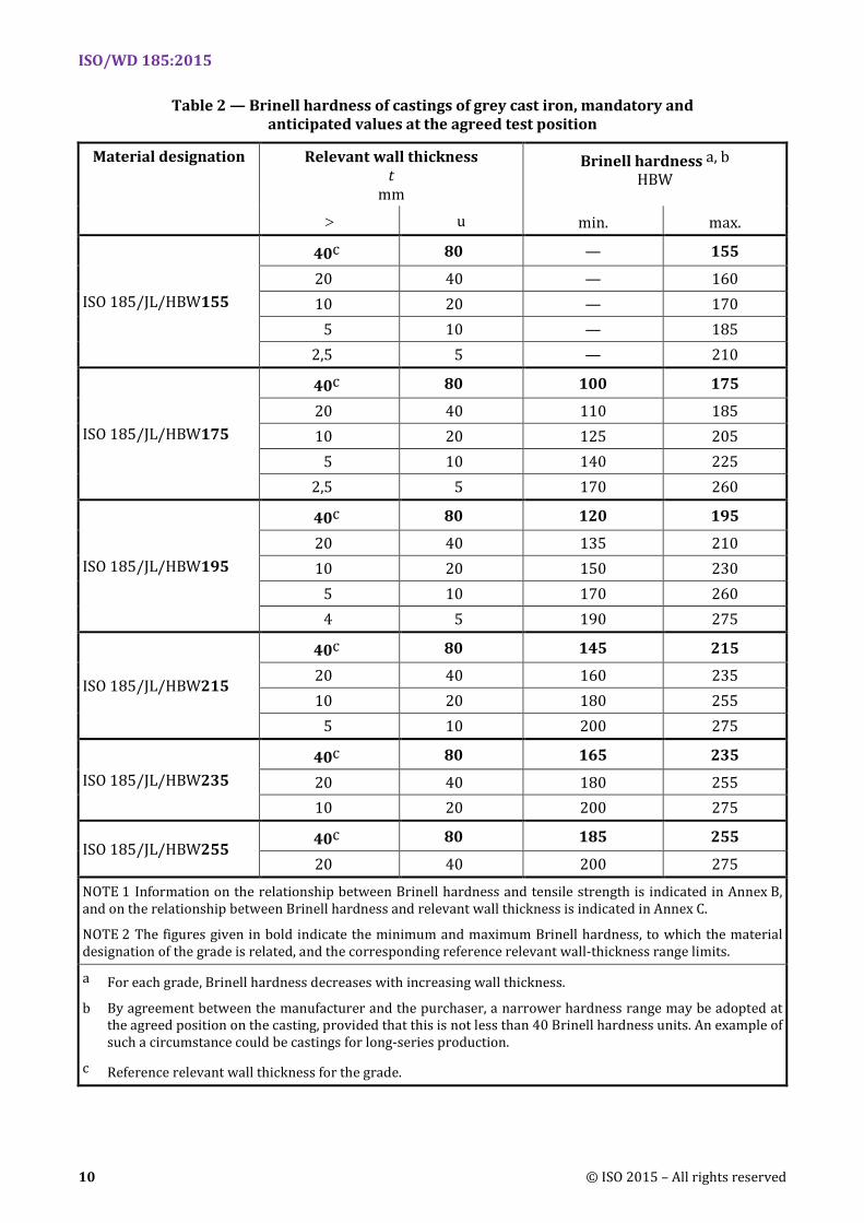
Table 2 — Brinell hardness of castings of grey cast iron, mandatory and anticipated values at the agreed test position
Material designation Relevant wall thickness t
mm
Brinell hardness a, b HBW
> u min. max.
ISO 185/JL/HBW155
40c 80 — 155
20 40 — 160 10 20 — 170
5 10 — 185 2,5 5 — 210
ISO 185/JL/HBW175
40c 80 100 175
20 40 110 185 10 20 125 205
5 10 140 225 2,5 5 170 260
ISO 185/JL/HBW195
40c 80 120 195
20 40 135 210 10 20 150 230
5 10 170 260 4 5 190 275
ISO 185/JL/HBW215
40c 80 145 215
20 40 160 235 10 20 180 255
5 10 200 275
ISO 185/JL/HBW235 40c 80 165 235
20 40 180 255 10 20 200 275
ISO 185/JL/HBW255 40c 80 185 255
20 40 200 275
NOTE 1 Information on the relationship between Brinell hardness and tensile strength is indicated in Annex B, and on the relationship between Brinell hardness and relevant wall thickness is indicated in Annex C.
NOTE 2 The figures given in bold indicate the minimum and maximum Brinell hardness, to which the material designation of the grade is related, and the corresponding reference relevant wall-thickness range limits.
a For each grade, Brinell hardness decreases with increasing wall thickness.
b By agreement between the manufacturer and the purchaser, a narrower hardness range may be adopted at the agreed position on the casting, provided that this is not less than 40 Brinell hardness units. An example of such a circumstance could be castings for long-series production.
c Reference relevant wall thickness for the grade.
ISO/WD 185:2015
© ISO 2015 – All rights reserved 11
8 Sampling
8.1 General
Samples shall be supplied in order to characterize the grade of the material.
If heat treatment is used to modify the properties of the material, then the samples shall be heat-treated in the same way as the castings they represent.
8.2 Tensile test
8.2.1 Separately cast samples
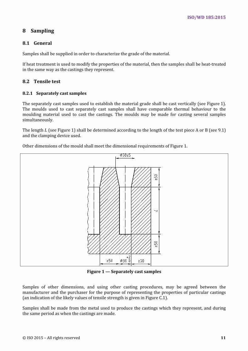
The separately cast samples used to establish the material grade shall be cast vertically (see Figure 1). The moulds used to cast separately cast samples shall have comparable thermal behaviour to the moulding material used to cast the castings. The moulds may be made for casting several samples simultaneously.
The length L (see Figure 1) shall be determined according to the length of the test piece A or B (see 9.1) and the clamping device used.
Other dimensions of the mould shall meet the dimensional requirements of Figure 1.
Figure 1 — Separately cast samples
Samples of other dimensions, and using other casting procedures, may be agreed between the manufacturer and the purchaser for the purpose of representing the properties of particular castings (an indication of the likely values of tensile strength is given in Figure C.1).
Samples shall be made from the metal used to produce the castings which they represent, and during the same period as when the castings are made.
ISO/WD 185:2015
12 © ISO 2015 – All rights reserved
The frequency of casting the separately cast samples shall be in accordance with the in-process quality assurance procedures adopted by the manufacturer.
The samples shall be removed from the mould at a temperature u 500 °C.
NOTE By agreement between the manufacturer and the purchaser, samples may be removed from the mould at a temperature W 500 °C, if the castings are also to be removed from the moulds at this higher temperature.
8.2.2 Cast-on samples
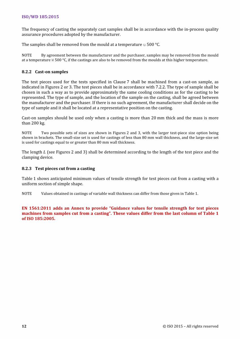
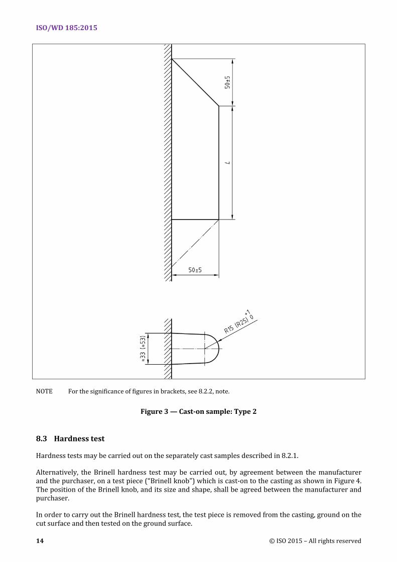
The test pieces used for the tests specified in Clause 7 shall be machined from a cast-on sample, as indicated in Figures 2 or 3. The test pieces shall be in accordance with 7.2.2. The type of sample shall be chosen in such a way as to provide approximately the same cooling conditions as for the casting to be represented. The type of sample, and the location of the sample on the casting, shall be agreed between the manufacturer and the purchaser. If there is no such agreement, the manufacturer shall decide on the type of sample and it shall be located at a representative position on the casting.
Cast-on samples should be used only when a casting is more than 20 mm thick and the mass is more than 200 kg.
NOTE Two possible sets of sizes are shown in Figures 2 and 3, with the larger test-piece size option being shown in brackets. The small-size set is used for castings of less than 80 mm wall thickness, and the large-size set is used for castings equal to or greater than 80 mm wall thickness.
The length L (see Figures 2 and 3) shall be determined according to the length of the test piece and the clamping device.
8.2.3 Test pieces cut from a casting
Table 1 shows anticipated minimum values of tensile strength for test pieces cut from a casting with a uniform section of simple shape.
NOTE Values obtained in castings of variable wall thickness can differ from those given in Table 1.
EN 1561:2011 adds an Annex to provide “Guidance values for tensile strength for test pieces machines from samples cut from a casting”. These values differ from the last column of Table 1 of ISO 185:2005.
ISO/WD 185:2015
© ISO 2015 – All rights reserved 13
NOTE For the significance of figures in brackets, see 8.2.2, note.
Figure 2 — Cast-on sample: Type 1
ISO/WD 185:2015
14 © ISO 2015 – All rights reserved
NOTE For the significance of figures in brackets, see 8.2.2, note.
Figure 3 — Cast-on sample: Type 2
8.3 Hardness test
Hardness tests may be carried out on the separately cast samples described in 8.2.1.
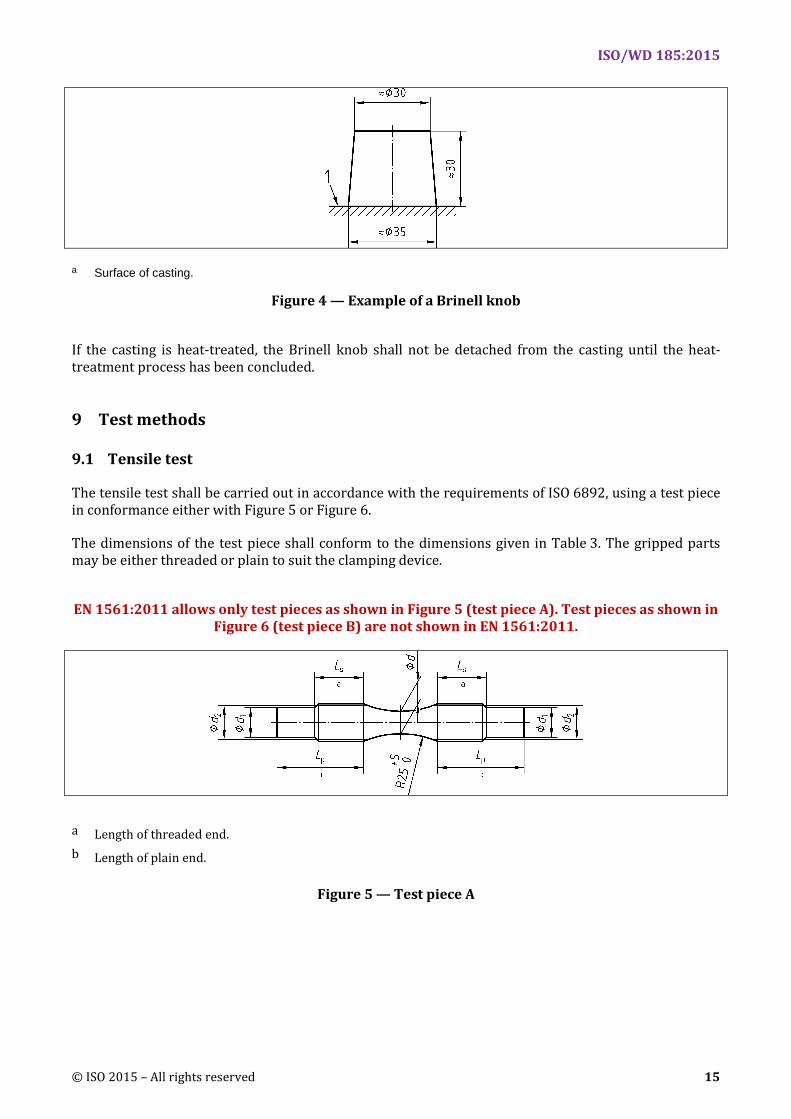
Alternatively, the Brinell hardness test may be carried out, by agreement between the manufacturer and the purchaser, on a test piece (“Brinell knob”) which is cast-on to the casting as shown in Figure 4. The position of the Brinell knob, and its size and shape, shall be agreed between the manufacturer and purchaser.
In order to carry out the Brinell hardness test, the test piece is removed from the casting, ground on the cut surface and then tested on the ground surface.
ISO/WD 185:2015
© ISO 2015 – All rights reserved 15
a Surface of casting.
Figure 4 — Example of a Brinell knob
If the casting is heat-treated, the Brinell knob shall not be detached from the casting until the heat-treatment process has been concluded.
9 Test methods
9.1 Tensile test
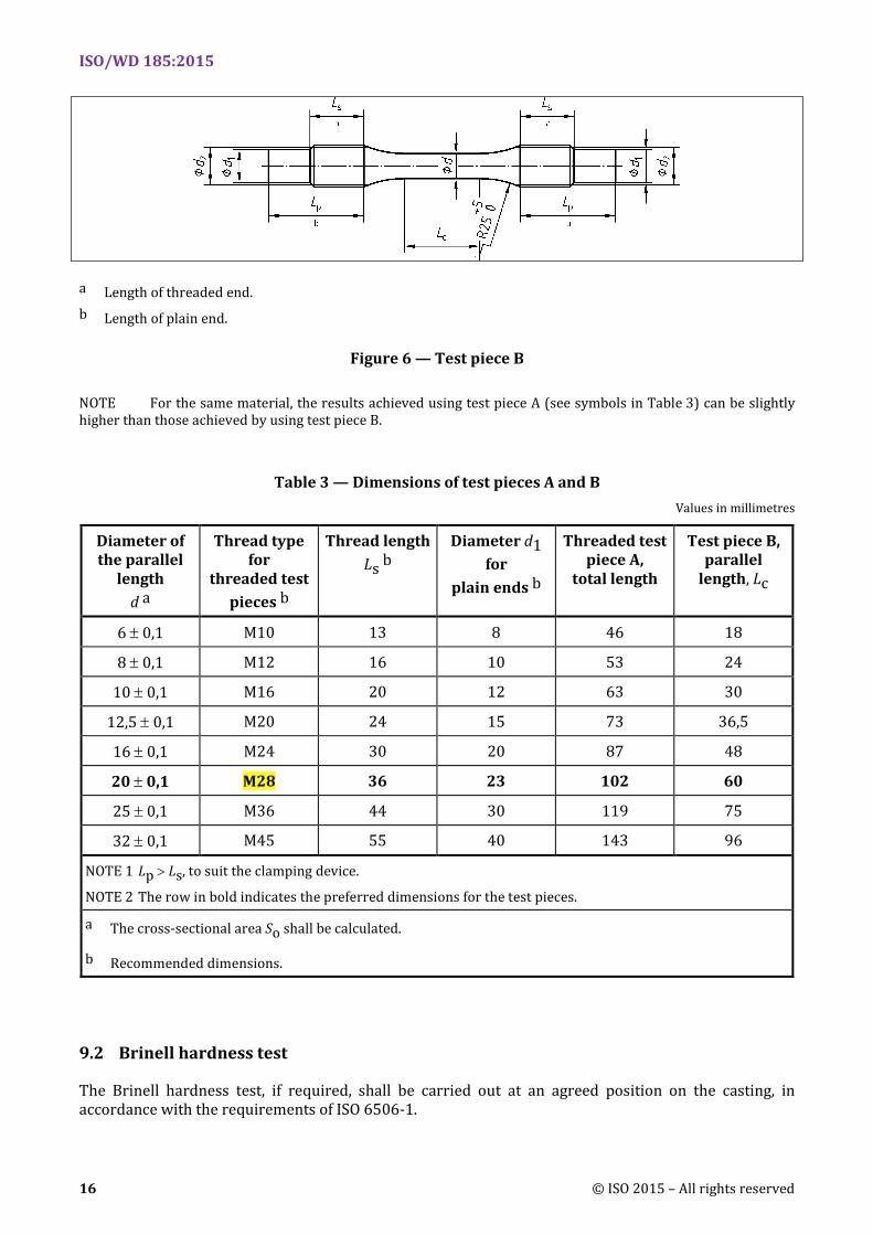
The tensile test shall be carried out in accordance with the requirements of ISO 6892, using a test piece in conformance either with Figure 5 or Figure 6.
The dimensions of the test piece shall conform to the dimensions given in Table 3. The gripped parts may be either threaded or plain to suit the clamping device.
EN 1561:2011 allows only test pieces as shown in Figure 5 (test piece A). Test pieces as shown in Figure 6 (test piece B) are not shown in EN 1561:2011.
a Length of threaded end. b Length of plain end.
Figure 5 — Test piece A
ISO/WD 185:2015
16 © ISO 2015 – All rights reserved
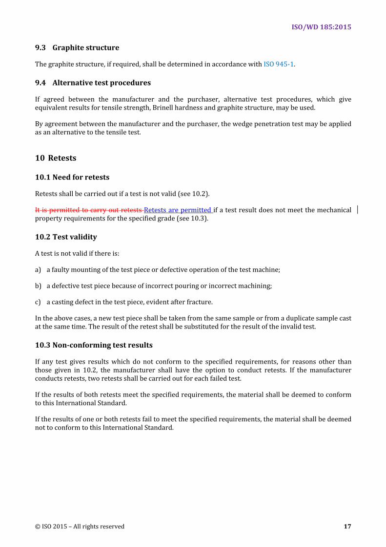
a Length of threaded end. b Length of plain end.
Figure 6 — Test piece B
NOTE For the same material, the results achieved using test piece A (see symbols in Table 3) can be slightly higher than those achieved by using test piece B.
Table 3 — Dimensions of test pieces A and B Values in millimetres
Diameter of the parallel
length d a
Thread type for
threaded test pieces b
Thread length Ls b
Diameter d1 for
plain ends b
Threaded test piece A,
total length
Test piece B, parallel
length, Lc
6 ± 0,1 M10 13 8 46 18
8 ± 0,1 M12 16 10 53 24
10 ± 0,1 M16 20 12 63 30
12,5 ± 0,1 M20 24 15 73 36,5
16 ± 0,1 M24 30 20 87 48
20 ± 0,1 M28 36 23 102 60
25 ± 0,1 M36 44 30 119 75
32 ± 0,1 M45 55 40 143 96
NOTE 1 Lp > Ls, to suit the clamping device.
NOTE 2 The row in bold indicates the preferred dimensions for the test pieces.
a The cross-sectional area So shall be calculated.
b Recommended dimensions.
9.2 Brinell hardness test
The Brinell hardness test, if required, shall be carried out at an agreed position on the casting, in accordance with the requirements of ISO 6506-1.
ISO/WD 185:2015
© ISO 2015 – All rights reserved 17
9.3 Graphite structure
The graphite structure, if required, shall be determined in accordance with ISO 945-1.
9.4 Alternative test procedures
If agreed between the manufacturer and the purchaser, alternative test procedures, which give equivalent results for tensile strength, Brinell hardness and graphite structure, may be used.
By agreement between the manufacturer and the purchaser, the wedge penetration test may be applied as an alternative to the tensile test.
10 Retests
10.1 Need for retests
Retests shall be carried out if a test is not valid (see 10.2).
It is permitted to carry out retests Retests are permitted if a test result does not meet the mechanical property requirements for the specified grade (see 10.3).
10.2 Test validity
A test is not valid if there is:
a) a faulty mounting of the test piece or defective operation of the test machine;
b) a defective test piece because of incorrect pouring or incorrect machining;
c) a casting defect in the test piece, evident after fracture.
In the above cases, a new test piece shall be taken from the same sample or from a duplicate sample cast at the same time. The result of the retest shall be substituted for the result of the invalid test.
10.3 Non-conforming test results
If any test gives results which do not conform to the specified requirements, for reasons other than those given in 10.2, the manufacturer shall have the option to conduct retests. If the manufacturer conducts retests, two retests shall be carried out for each failed test.
If the results of both retests meet the specified requirements, the material shall be deemed to conform to this International Standard.
If the results of one or both retests fail to meet the specified requirements, the material shall be deemed not to conform to this International Standard.
ISO/WD 185:2015
18 © ISO 2015 – All rights reserved
Annex A (informative)
Additional information on mechanical and physical properties in addition
to that given in Tables 1 and 2
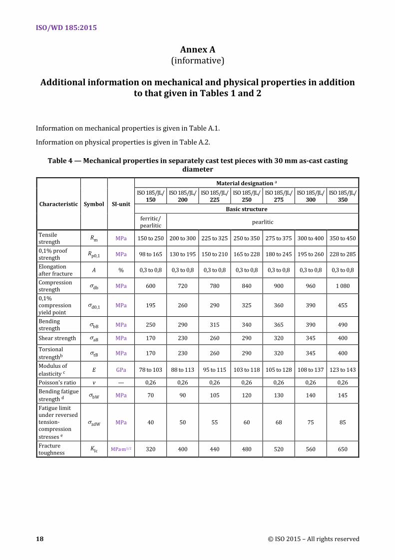
Information on mechanical properties is given in Table A.1.
Information on physical properties is given in Table A.2.
Table 4 — Mechanical properties in separately cast test pieces with 30 mm as-cast casting diameter
Characteristic Symbol SI-unit
Material designation a ISO 185/JL/
150 ISO 185/JL/
200 ISO 185/JL/
225 ISO 185/JL/
250 ISO 185/JL/
275 ISO 185/JL/
300 ISO 185/JL/
350 Basic structure
ferritic/ pearlitic pearlitic
Tensile strength
Rm MPa 150 to 250 200 to 300 225 to 325 250 to 350 275 to 375 300 to 400 350 to 450
0,1% proof strength
Rp0,1 MPa 98 to 165 130 to 195 150 to 210 165 to 228 180 to 245 195 to 260 228 to 285
Elongation after fracture A % 0,3 to 0,8 0,3 to 0,8 0,3 to 0,8 0,3 to 0,8 0,3 to 0,8 0,3 to 0,8 0,3 to 0,8
Compression strength
σdb MPa 600 720 780 840 900 960 1 080
0,1% compression yield point
σd0,1 MPa 195 260 290 325 360 390 455
Bending strength
σbB MPa 250 290 315 340 365 390 490
Shear strength σaB MPa 170 230 260 290 320 345 400
Torsional strengthb
σtB MPa 170 230 260 290 320 345 400
Modulus of elasticity c E GPa 78 to 103 88 to 113 95 to 115 103 to 118 105 to 128 108 to 137 123 to 143
Poisson's ratio v — 0,26 0,26 0,26 0,26 0,26 0,26 0,26 Bending fatigue strength d
σbW MPa 70 90 105 120 130 140 145
Fatigue limit under reversed tension- compression stresses e
σzdW MPa 40 50 55 60 68 75 85
Fracture toughness
KIc MPa.m1/2 320 400 440 480 520 560 650
ISO/WD 185:2015
© ISO 2015 – All rights reserved 19
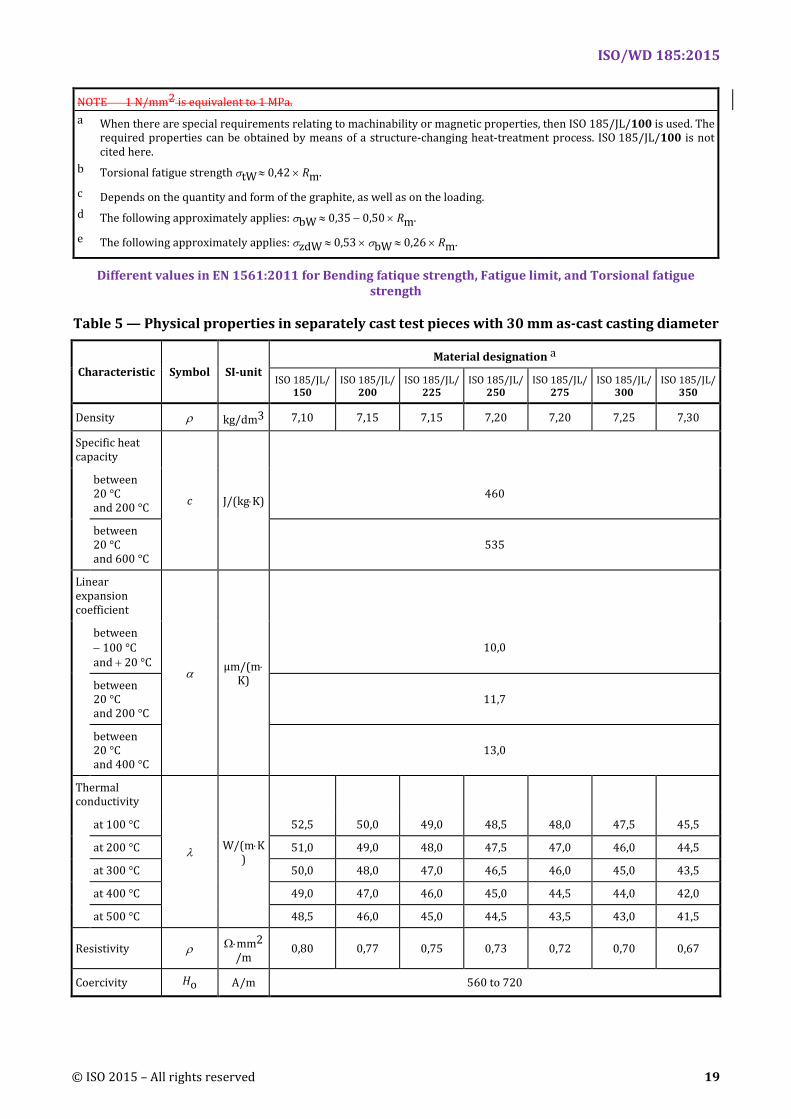
NOTE 1 N/mm2 is equivalent to 1 MPa. a When there are special requirements relating to machinability or magnetic properties, then ISO 185/JL/100 is used. The
required properties can be obtained by means of a structure-changing heat-treatment process. ISO 185/JL/100 is not cited here.
b Torsional fatigue strength σtW ≈ 0,42 × Rm.
c Depends on the quantity and form of the graphite, as well as on the loading. d The following approximately applies: σbW ≈ 0,35 − 0,50 × Rm.
e The following approximately applies: σzdW ≈ 0,53 × σbW ≈ 0,26 × Rm.
Different values in EN 1561:2011 for Bending fatique strength, Fatigue limit, and Torsional fatigue strength
Table 5 — Physical properties in separately cast test pieces with 30 mm as-cast casting diameter
Characteristic Symbol SI-unit Material designation a
ISO 185/JL/150
ISO 185/JL/200
ISO 185/JL/225
ISO 185/JL/250
ISO 185/JL/275
ISO 185/JL/300
ISO 185/JL/350
Density ρ kg/dm3 7,10 7,15 7,15 7,20 7,20 7,25 7,30
Specific heat capacity
c J/(kg⋅K)
between 20 °C and 200 °C
460
between 20 °C and 600 °C
535
Linear expansion coefficient
α µm/(m⋅K)
between − 100 °C and + 20 °C
10,0
between 20 °C and 200 °C
11,7
between 20 °C and 400 °C
13,0
Thermal conductivity
λ W/(m⋅K)
at 100 °C 52,5 50,0 49,0 48,5 48,0 47,5 45,5
at 200 °C 51,0 49,0 48,0 47,5 47,0 46,0 44,5
at 300 °C 50,0 48,0 47,0 46,5 46,0 45,0 43,5
at 400 °C 49,0 47,0 46,0 45,0 44,5 44,0 42,0
at 500 °C 48,5 46,0 45,0 44,5 43,5 43,0 41,5
Resistivity ρ Ω⋅mm2/m
0,80 0,77 0,75 0,73 0,72 0,70 0,67
Coercivity Ho A/m 560 to 720
ISO/WD 185:2015
20 © ISO 2015 – All rights reserved
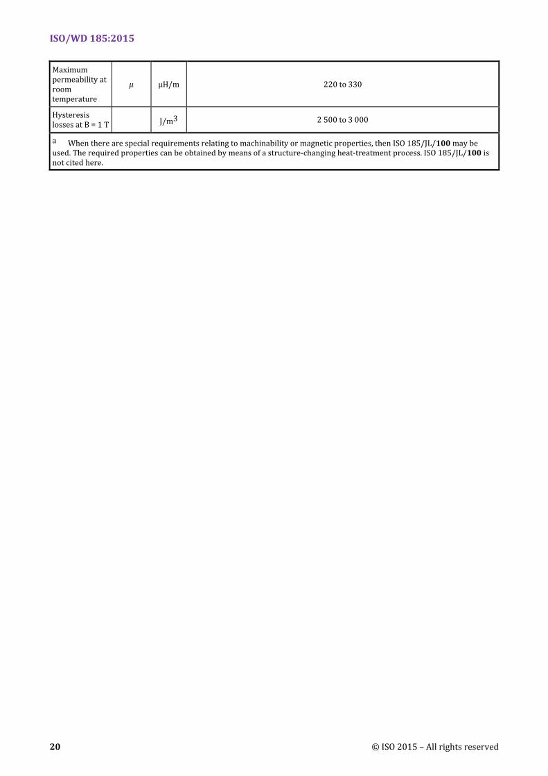
Maximum permeability at room temperature
µ µH/m 220 to 330
Hysteresis losses at B = 1 T J/m3 2 500 to 3 000
a When there are special requirements relating to machinability or magnetic properties, then ISO 185/JL/100 may be used. The required properties can be obtained by means of a structure-changing heat-treatment process. ISO 185/JL/100 is not cited here.
ISO/WD 185:2015
© ISO 2015 – All rights reserved 21
Annex B (informative)
Additional information on the relationship between hardness and tensile
strength of grey cast irons
B.1 Introduction
Hardness and tensile strength, as well as modulus of elasticity and the modulus of rigidity of grey cast iron of a given grade, are approximately related to each other. In most cases, an increase in the value of one property results in an increase in the values of other properties. Grey cast irons naturally divide into a family or series of grades having different relative hardness (RH) or tensile-strength-to-hardness (T/H) ratios. This Annex briefly discusses RH and T/H for grey cast irons.
B.2 Relative hardness
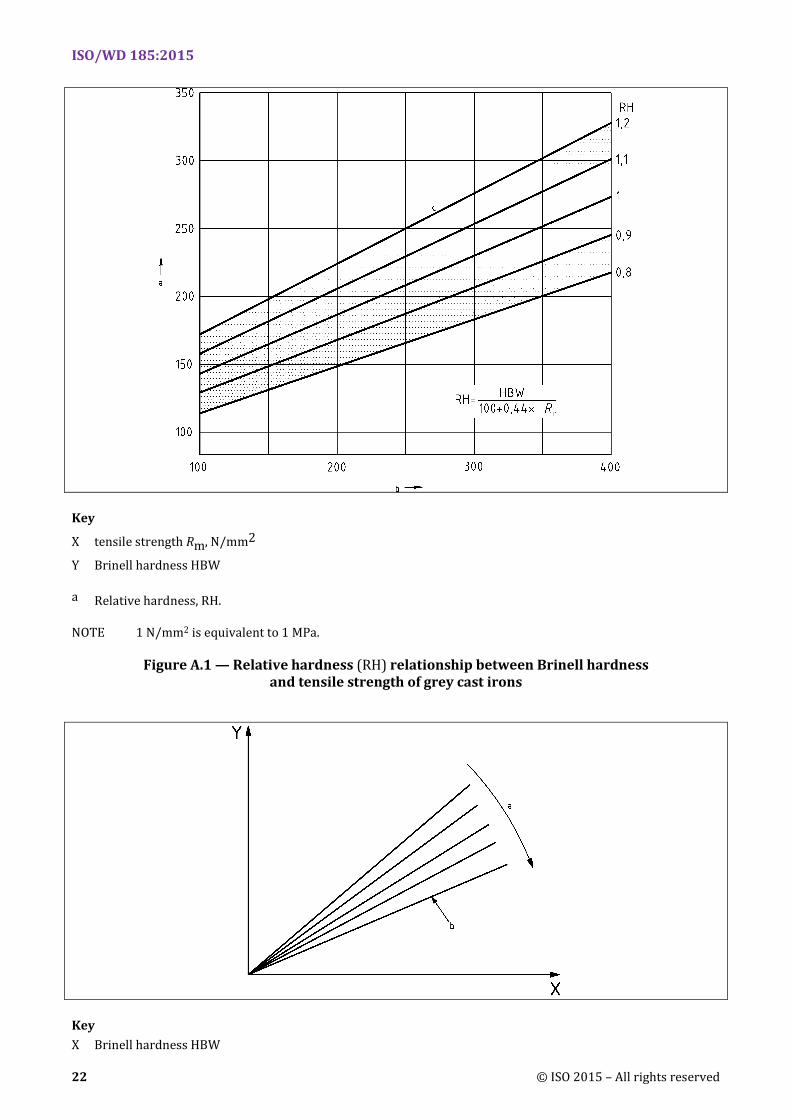
The following empirical relationship between Brinell hardness (HBW) and tensile strength Rm exists:
HBW = RH × (A + B × Rm)
Commonly accepted values for the constants are:
A = 100
B = 0,44
where RH is the relative hardness.
RH has been found to vary between 0,8 and 1,2 (see Figure B.1).
The factor RH is influenced mainly by the raw materials, the melting process, and the metallurgical working method. Within one foundry, these influences can be maintained nearly constant. Therefore, the manufacturer can indicate both hardness and the corresponding tensile strength.
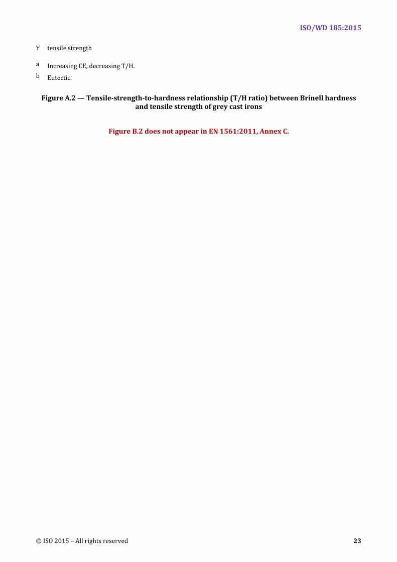
B.3 Tensile-strength-to-hardness ratio
Tensile-strength-to-hardness (T/H) ratios are regulated by the eutectic graphite content, up to the eutectic composition shown in Figure B.2, with carbon equivalent (CE) as the graphite parameter. Using tensile strength in N/mm2, or MPa and Brinell hardness in HBW, the T/H ratios of grey cast irons range from approximately 0,8 to 1,4. A decline in T/H ratio continues as CE increases above the eutectic, but at a much smaller and less predictable rate. Constant T/H lines in Figure B.2 are essentially lines of constant graphite effect on mechanical properties. Properties sensitive to both graphite and matrix, such as bulk tensile strength and bulk hardness, vary in constant proportionality to each other and to their matrix counterparts (matrix tensile strength and matrix hardness) along constant T/H lines. Elastic modulus and damping capacity vary mainly only with graphite and are, therefore, highly uniform along the constant T/H lines. Since these lines are also lines of constant eutectic graphite and carbon equivalent, the most important castability parameters, they are logical grade lines for foundry control, as well as for mechanical property control.
ISO/WD 185:2015
22 © ISO 2015 – All rights reserved
Key
X tensile strength Rm, N/mm2
Y Brinell hardness HBW
a Relative hardness, RH.
NOTE 1 N/mm2 is equivalent to 1 MPa.
Figure A.1 — Relative hardness (RH) relationship between Brinell hardness and tensile strength of grey cast irons
Key X Brinell hardness HBW
ISO/WD 185:2015
© ISO 2015 – All rights reserved 23
Y tensile strength
a Increasing CE, decreasing T/H. b Eutectic.
Figure A.2 — Tensile-strength-to-hardness relationship (T/H ratio) between Brinell hardness and tensile strength of grey cast irons
Figure B.2 does not appear in EN 1561:2011, Annex C.
ISO/WD 185:2015
24 © ISO 2015 – All rights reserved
Annex C (informative)
Additional information on the relationship between tensile strength,
hardness and wall thickness of grey iron castings
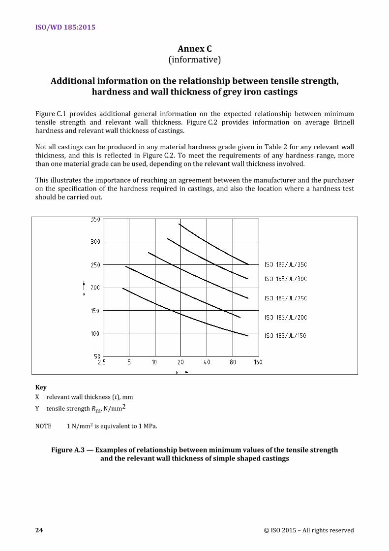
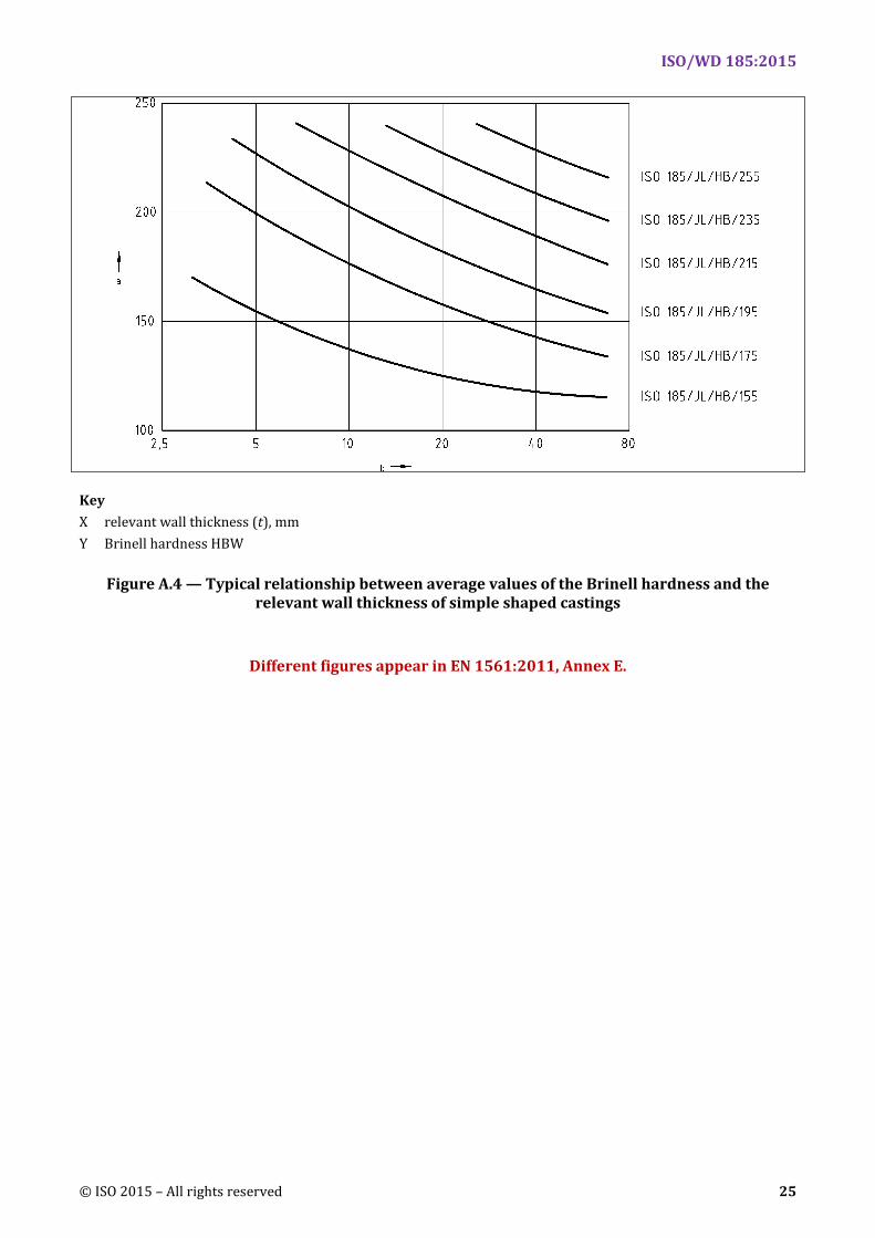
Figure C.1 provides additional general information on the expected relationship between minimum tensile strength and relevant wall thickness. Figure C.2 provides information on average Brinell hardness and relevant wall thickness of castings.
Not all castings can be produced in any material hardness grade given in Table 2 for any relevant wall thickness, and this is reflected in Figure C.2. To meet the requirements of any hardness range, more than one material grade can be used, depending on the relevant wall thickness involved.
This illustrates the importance of reaching an agreement between the manufacturer and the purchaser on the specification of the hardness required in castings, and also the location where a hardness test should be carried out.
Key X relevant wall thickness (t), mm
Y tensile strength Rm, N/mm2
NOTE 1 N/mm2 is equivalent to 1 MPa.
Figure A.3 — Examples of relationship between minimum values of the tensile strength and the relevant wall thickness of simple shaped castings
ISO/WD 185:2015
© ISO 2015 – All rights reserved 25
Key X relevant wall thickness (t), mm Y Brinell hardness HBW
Figure A.4 — Typical relationship between average values of the Brinell hardness and the relevant wall thickness of simple shaped castings
Different figures appear in EN 1561:2011, Annex E.
ISO/WD 185:2015
26 © ISO 2015 – All rights reserved
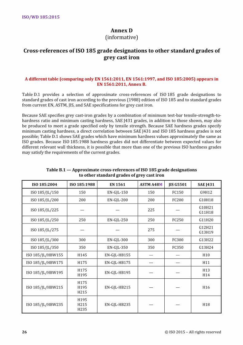
Annex D (informative)
Cross-references of ISO 185 grade designations to other standard grades of
grey cast iron
A different table (comparing only EN 1561:2011, EN 1561:1997, and ISO 185:2005) appears in EN 1561:2011, Annex B.
Table D.1 provides a selection of approximate cross-references of ISO 185 grade designations to standard grades of cast iron according to the previous (1988) edition of ISO 185 and to standard grades from current EN, ASTM, JIS, and SAE specifications for grey cast iron.
Because SAE specifies grey cast-iron grades by a combination of minimum test-bar tensile-strength-to-hardness ratio and minimum casting hardness, SAE J431 grades, in addition to those shown, may also be produced to meet a grade specified only by tensile strength. Because SAE hardness grades specify minimum casting hardness, a direct correlation between SAE J431 and ISO 185 hardness grades is not possible; Table D.1 shows SAE grades which have minimum hardness values approximately the same as ISO grades. Because ISO 185:1988 hardness grades did not differentiate between expected values for different relevant wall thickness, it is possible that more than one of the previous ISO hardness grades may satisfy the requirements of the current grades.
Table B.1 — Approximate cross-references of ISO 185 grade designations to other standard grades of grey cast iron
ISO 185:2004 ISO 185:1988 EN 1561 ASTM A48M JIS G5501 SAE J431
ISO 185/JL/150 150 EN-GJL-150 150 FC150 G9H12
ISO 185/JL/200 200 EN-GJL-200 200 FC200 G10H18
ISO 185/JL/225 — — 225 — G10H21 G11H18
ISO 185/JL/250 250 EN-GJL-250 250 FC250 G11H20
ISO 185/JL/275 — — 275 — G12H21 G13H19
ISO 185/JL/300 300 EN-GJL-300 300 FC300 G13H22
ISO 185/JL/350 350 EN-GJL-350 350 FC350 G13H24
ISO 185/JL/HBW155 H145 EN-GJL-HB155 — — H10
ISO 185/JL/HBW175 H175 EN-GJL-HB175 — — H11
ISO 185/JL/HBW195 H175 H195 EN-GJL-HB195 — — H13
H14
ISO 185/JL/HBW215 H175 H195 H215
EN-GJL-HB215 — — H16
ISO 185/JL/HBW235 H195 H215 H235
EN-GJL-HB235 — — H18
ISO/WD 185:2015
© ISO 2015 – All rights reserved 27
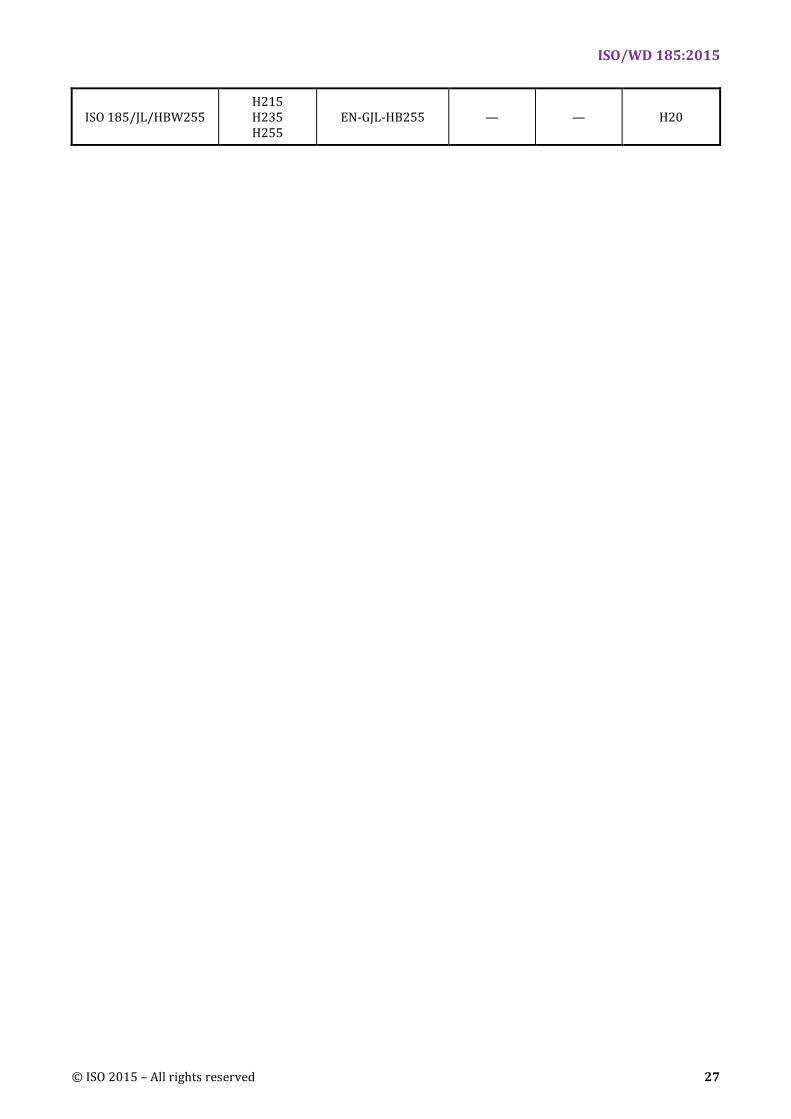
ISO 185/JL/HBW255 H215 H235 H255
EN-GJL-HB255 — — H20
ISO/WD 185:2015
28 © ISO 2015 – All rights reserved
Annex E (informative)
Wedge penetration test
This annex does not appear in ISO 185:2005, but does appear in EN 1561:2011.
ISO/WD 185:2015
© ISO 2015 – All rights reserved 29
Bibliography
[1] EN 1561, Founding — Grey cast irons
[2] ASTM A48, Standard Specification for Gray Iron Castings
[3] JIS G 5501, Grey iron castings
[4] SAE J431, Automotive Gray Iron Castings