Embed Size (px)
Citation preview

Mygo Seating SystemUser Instructions

The Mygo Seating System has been designed to offer a high level of postural positioning while enabling function and mobility. This manual shows how you can quickly, easily and safely make use of all the functions. The instructions on safety and maintenance will ensure that you will enjoy the use of this product for a long time.
Contents
01 Intended use02 Declaration of conformity03 Terms of warranty04 Product history record 05 Product training record06 Safety information07 How to unpack and assemble the seating system 08 The back pack09 Fitting the cushions10 Clinical setup for postural management11 Frequent adjustments for daily use12 Cleaning & care information13 Daily product inspection14 Annual product inspection15 Reissuing Leckey products16 Product servicing 17 Technical information

1. Intended UseThe Mygo Seating System is an activity chair which has been designed for children with disabilities for use at home, in the school environment or outside, if used on a mobility base. Size 1 is suitable for children aged 3-10 years and Size 2 is suitable for 8-14 years. The seating system has a maximum user weight of 50kg (110lbs) for Size 1 and 60kg (132lbs) for Size 2. The seating system is modular and can be used with a choice of indoor or outdoor chassis. The Hi-low chassis has been designed for use indoors but can also be used outdoors on a level surface. The Hi-low chassis should never be exposed to the elements as this may corrode the metal components.
The Mygo seat unit will interface with a range of mobility bases, the details of which can be found at our websitewww.leckey.com
2. Declaration of ConformityJames Leckey Design Ltd as manufacturerwith sole responsibility declares that theMygo Seating System conforms to therequirements of the 93/42/EEC Guidelines,Medical Device Regulations 2002 andEN12182 Technical aids for disabledpersons and test methods.
3. Terms of WarrantyThe warranty applies only when the product is used according to the specified conditions and for the intended purposes, following all manufacturers’ recommendations (also see general terms of sales, delivery and payment). A three
6.1 Always read instructions fully before use.
6.2 To improve safety we recommend that users should not be left unattended at any time whilst using Leckey equipment.
6.3 Only use Leckey approved components with your product. Never modify the product in any way. Failure to follow instructions may put the user or carer at risk and will invalidate the warranty on the product.
6.4 If in any doubt to the continued safe use of your Leckey product or if any parts should fail, please cease using the product and contact our Customer Care Team or your local dealer as soon as possible.
6.5 Carry out all positional adjustments and ensure that they are securely fastened before you put the user into the product. Some adjustments may require the use of a tool which is provided with each product. Keep all tools out of reach of children.
6.6 When putting the user into a seating system, both for positional and safety reasons, always secure the pelvic harness first.
6.7 When the product is stationary ensure that all castors are locked and facing away from the base, as this will improve product stability. This is especially important when the tilt-in-space or back recline facility is in use.
6.8 When the seat is in use on a Hi-low chassis please ensure that the height adjustment pedal and tilt-in-space lever are locked off and cannot be adjusted accidentally by other children.
6.9 When the Leckey seating systems are used on the Hi-low chassis we do not recommend that users are moved over uneven surfaces when in the equipment. All due care and attention should be taken if transporting in and out of the seat.
6.10 Never leave the product on a sloping surface, greater than 5 degrees. Always remember to lock all the castors.
6.11 Only use the push handle to steer and move the seat from one area to another. Never use the tray or headrest for this purpose.
6.12 The product contains components which could present a choking hazard to small children. Always check that locking knobs and bolts within the child’s reach are tightened and secure at all times.
6.13 Leckey products comply with fire saftey regulations in accordance with EN12182. However the product contains plastic components and therefore should be kept away from all direct sources of heat including naked flames, cigarettes and gas heaters.
6.14 Do not place objects hotter than 40oC on the tray.
year warranty is provided on all Leckey manufactured products and components.
4. Product History RecordYour Leckey product is classified as a Class 1 Medical device and as such should only be prescribed, set up or reissued for use by a technically competent person who has been trained in the use of this product. Leckey recommend that a written record is maintained to provide details of all setups, reissue inspections and annual inspections of this product.
5. Product Training Record (Parents, Teachers & Carers)Your Leckey product is a prescribed Class 1 Medical Device and as such Leckey recommend that parents, teachers and carers using the equipment should be made aware of the following sections of this user manual by a technically competent person:
Section 6 Safety Information
Section 11 Frequent Adjustments for Daily use
Section 12 Cleaning and Care
Section 13 Daily Product Inspection
Leckey recommend that a written record is maintained of all those who have been trained in the correct use of this product.
6 Safety Information

The Mygo Seating System has been crash tested and passed for use in vehicles. It has been tested in its complete configuration on a surrogate base with a Leckey head support attached.
If the Mygo Seating System is being used in a vehicle the following points must be adhered to:
The Mygo Seating System must be positioned forward facing and used with an Unwin Restraint System and a head support which should be suitably positioned at all times during transportation. The head support is available as an optional accessory with the Mygo Seating System.
The Mygo Seating System is crash tested and meets the requirements of ISO16840 part 4. For further details please contact our Customer Care Team.
ImportantThese crash test details refer to the Mygo Seating System and interface plate only. If you are using the Mygo Seating System on a wheelchair base, please refer to the wheelchair manufacturer’s handbook for crash test details.
Mygo Seating System – Crash Test
6.15 Clean the product regularly. Do not use abrasive cleaners. Carry out maintenence checks on a regular basis to ensure your product is in good working condition.
6.16 The product is designed for indoor use and when not in use should be stored in a dry place that is not subjected to extremes of temperature. The safe operating temperature range of the product is +5 to +40 deg Celsius.
6.17 Always check the plastic hand knobs on the push handle are tightened securely before you move the seat unit.
6.18 Before using the seating system always check that the interface handle on the seat unit is fully engaged with the chassis. If the handle is not engaged properly the seat unit may come loose and could cause serious injury to the child or carer.
6.19 Please be aware of the gap on the underside of the Tray where a child could insert their finger between the metal bracket and the base of the plastic tray.
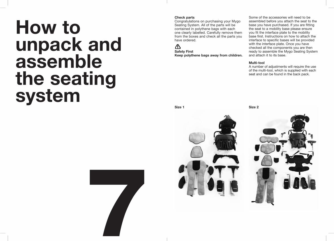
Check parts Congratulations on purchasing your Mygo Seating System. All of the parts will be contained in polythene bags with each one clearly labelled. Carefully remove them from the boxes and check all the parts you have ordered.
Safety FirstKeep polythene bags away from children.
Some of the accessories will need to be assembled before you attach the seat to the base you have purchased. If you are fitting the seat to a mobility base please ensure you fit the interface plate to the mobility base first. Instructions on how to attach the interface to specific bases will be provided with the interface plate. Once you have checked all the components you are then ready to assemble the Mygo Seating System and attach it to its base.
Multi-toolA number of adjustments will require the use of the multi-tool, which is supplied with each seat and can be found in the back pack.
How to unpack and assemble the seating system
7Size 1 Size 2

If using the Leckey footrests, remove the seat from the chassis and set the seating system upside down on a work surface. Open up the angle of the leg supports by releasing the two locking levers (A), shown, and set to the maximum width. Open the socket caps (B) and slide in the calf supports. Set to the desired position, with the footplates facing forward and retighten the socket cap bolts with the multi-tool.
Always make sure the foot plate is attached firmly.
7.2 Attaching the footrests (if ordered)
The backrest will be folded down for shipping. Raise it into the vertical position and, while doing so, slide the inner tube into the receiving outer tube.
Secure the backrest in an upright position and tighten the socket cap. Check that it is secure and does not move when pressure is applied. If the user thrusts forward or backwards they could cause injury to themselves or their carers.
Always make sure the backrest is attached securely.
Use caution when inserting inner tube as there could be possible finger nip.
7.1 Setting the backrest
A
BB

7.4 Attaching the push handle
The push handle is attached to the Hi-low chassis by inserting the two lower stems into the receiving tubes as shown. The push handle has safety poppers (A), which need to be pressed in when inserting the lower stems. Push the stems in until the poppers protrude from the other end of the receiving tubes. Secure the handle in place by tightening the locking knobs (B).
Check these regularly to make sure the knobs are tight, particularly if you are moving the product unit along corridors that may have uneven or sloping surfaces.
Adjust the height of the chassis to its maximum to reduce risk of back strain while attaching the seat unit. Refer to Section 11 on how to adjust the height of the chassis you have purchased.
First release the safety locking pin at the front of the seat. To do this pull the pin out and rotate through 90 degrees. Carefully lift the seat and place it into the chassis. At the rear of the underside of the seat you will see a receiving channel. Place this securely over the tube towards the back of the chassis. Pull the handle at the front of the seat unit up and then pivot the seat forward and down. Once the front of the seat is lowered fully, release the handle and push it forward to
ensure it has fully engaged on the front tube. Rotate the safety locking pin so it engages in front of the handle. If it hits the handle then the seat is not inserted properly. Remove and repeat process outlined above.
Always check the handle and locking pin are fully engaged before you place the child in the seating system. If the handle is not engaged properly the seat unit can come loose and could cause serious injury to the child or carer.
7.3 Attaching the seating system to the Hi-low chassis
B
A

7.7 Attaching the lateral supports
While holding the components together, remove the plastic knob and washer. Align the plastic angle adjuster mouldings and lateral bracket with the slot in the backrest and refit the washer and plastic knob.
7.5 Attaching the headrest
7.6 Attaching the shoulder section
To attach the head support slide the stem into the reducing sleeve (A) and receiving bracket. Ensure the slot in the reducing sleeve is aligned with the slot in the receiving bracket. Set to the desired position and secure using the hand lever (B).
The Mygo Seating System has been designed to interface with Whitmyer head supports. The Whitmyer Lynx head support (C) is attached in the same way as the Leckey headrest. To attach Whitmyer Pro-Series head supports remove the spacer collar (D) from the receiving bracket and lock the vertical stem in position using the ratchet handle.
To attach the shoulder section to a Size 1 Mygo, remove the headrest mounting bracket by removing the bolts (A). Insert the shoulder section bracket and supplied spacer plate between the backrest and the headrest mounting bracket. Bolt back together. Secure the two metal tabs with additional screws (B)provided with the new spacer plate. The screws are attached from the front. Check it is securely fastened.
B
C
AABA
D
B
B

7.8 Attaching the kneepads
Attach the kneepads with the snap fasteners to the knee guides on the sides of the upper legs supports.
7.10 Attaching the sandals
7.9 Inserting Attachment bolts on sandals
Place the sandal so that the attachment bolt goes through the slot in the footplate. To secure, on the underside of the footpate place the rubber washer (a), followed by the metal washer (b) and then the knob (c) onto the attachment bolt. To position the sandals simply loosen the knob (c) under the footplate, select the position you require and re-fasten the knob.
Insert the required attachment bolt (a) along with the retention plate (b). Place a rubber lid (c) on both the top and bottom of the sandal. Fasten using the four screws (d) provided. To remove or replace the attachment bolt, reverse this process.
2
1
C
AB
C
A1
2
3
B
D
C
C
D
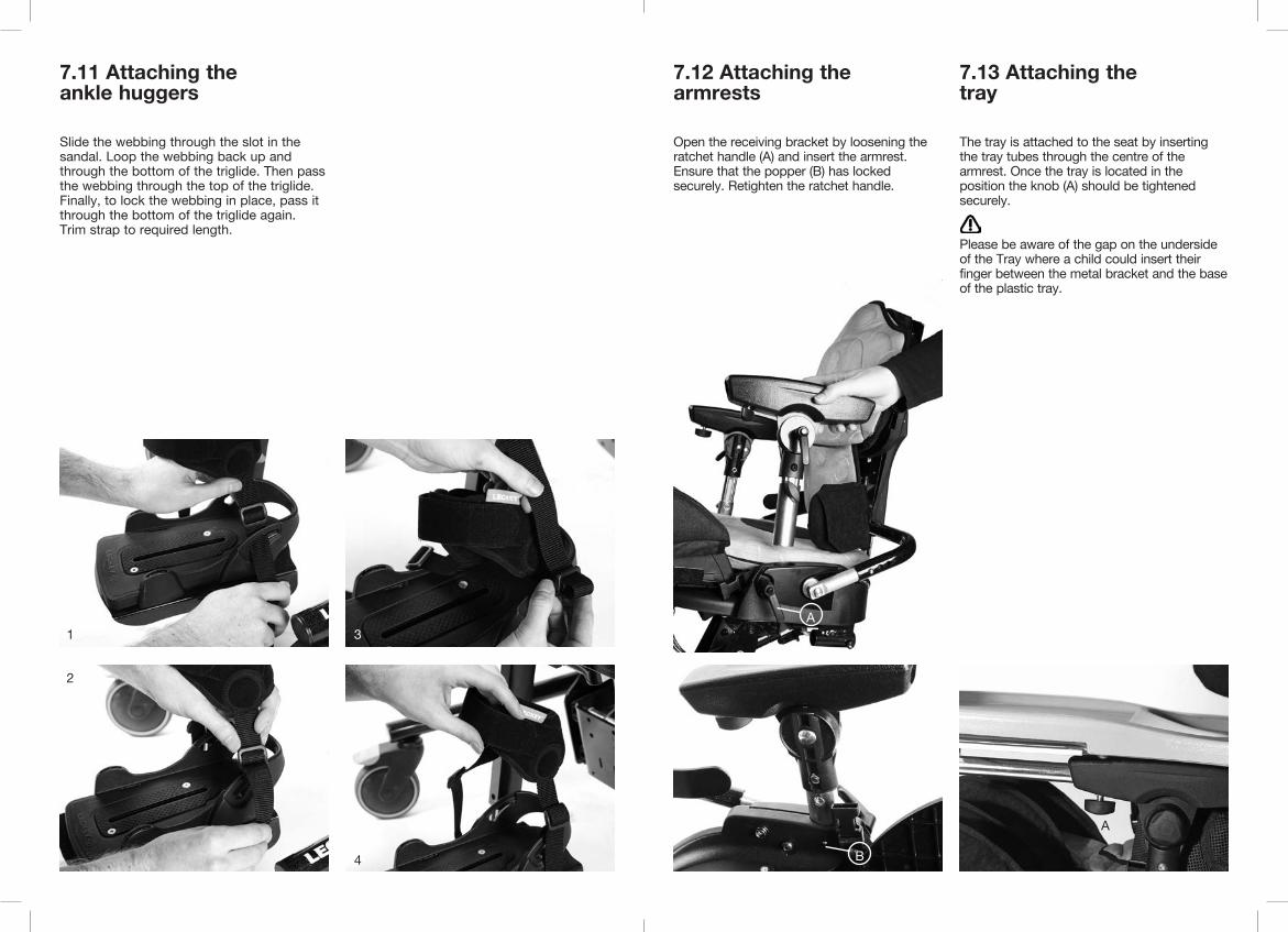
Slide the webbing through the slot in the sandal. Loop the webbing back up and through the bottom of the triglide. Then pass the webbing through the top of the triglide. Finally, to lock the webbing in place, pass it through the bottom of the triglide again. Trim strap to required length.
7.11 Attaching the ankle huggers
1
2
3
4
7.13 Attaching the tray
7.12 Attaching the armrests
The tray is attached to the seat by inserting the tray tubes through the centre of the armrest. Once the tray is located in the position the knob (A) should be tightened securely.
Please be aware of the gap on the underside of the Tray where a child could insert their finger between the metal bracket and the base of the plastic tray.
Open the receiving bracket by loosening the ratchet handle (A) and insert the armrest. Ensure that the popper (B) has locked securely. Retighten the ratchet handle.
A
A
B

7.15 Attaching the Hip Laterals
Hip laterals are used with the Pelvic Cradle.First, remove the Pelvic Harness brackets if required, by removing the screw and flange nut (A). Lift the piece of polypropylene on the front of the sacral support. Place the hip lateral brackets into the slots and attach using the flange nuts (B) and screws (C) provided. The flange nuts should go on the front side of the sacral support.
A
7.14 Attaching the grab rail
To attach the grab rail, insert the receiving brackets (A) in the tray slot and secure with the plastic knob (B). Repeat on the other side and then slide the tubes into the receiving brackets (A) and tighten the plastic knob (C).
B
AC
A
7.16 Retrofitting the Dynamic Backrest
To replace the standard static backrest with the dynamic backrest first of all you will need to remove the screw (c) at the top of the standard backrest assembly. To do this loosen the nut (a) using the Leckey tool and a 10mm spanner and remove the screw and washers (b).
Again using the Leckey tool and the 10mm spanner, loosen the nut (a) at the bottom of the standard backrest assembly then remove screw (c) saddle washers (d) and standard washers (b).

To fit the dynamic backrest, insert the strut into the bottom bracket as shown. Use the provided screw (c), nut (a), saddle washers (d) and standard washers (b) to secure in place. Please ensure that the screw thread protrudes through the nut (a).
Now raise the dynamic strut and insert into the top bracket as shown. Using the provided screw (c), nut (a) and washers (b), secure the new dynamic backrest in place as shown.
Ensure that the bolt goes through the centre of the assembly as shown (f). Finally fit the domed cap (e).
Use caution when assembling and fitting the dynamic backrest as there is a minor risk of finger nipping.
B
C
7.17 Attaching the obliquity pads
To attach the obliquity pads first remove the base cushion. Set the obliquity pad panel in place with the holes on the tab over the snap fastener. Insert foam as required and refit the base cushion.

7.18 Interfaces for wheelchair and pushchair bases
The set up and attachment of the Mygo seat to any mobility base should be completed by a technically competent person who is familiar with the set up of the mobility base.
Interface “A” attachment to 16” wide mobility baseThe universal interface has been designed to enable the Mygo Seat to be attached to any standard 16” (405mm) wide mobility base that has been constructed from 1” (25.4mm) side tubing.
Please refer to specific assembly instructions supplied with your interface for correct positioning on your base.
The Interface plate should be fitted by a qualified technician who is technically competent in the set up of the mobility base. The position of push handles, leg hangers and armrests on the mobility base may need to be adjusted depending on the size and weight of the child to ensure the stability of the seat.
Always refer to the mobility base manufacturer’s guide lines for correct set up, paying particular attention to product centre of gravity and stability.
Users should not be left unattended at any time whilst using Leckey equipment.
The backpack
8
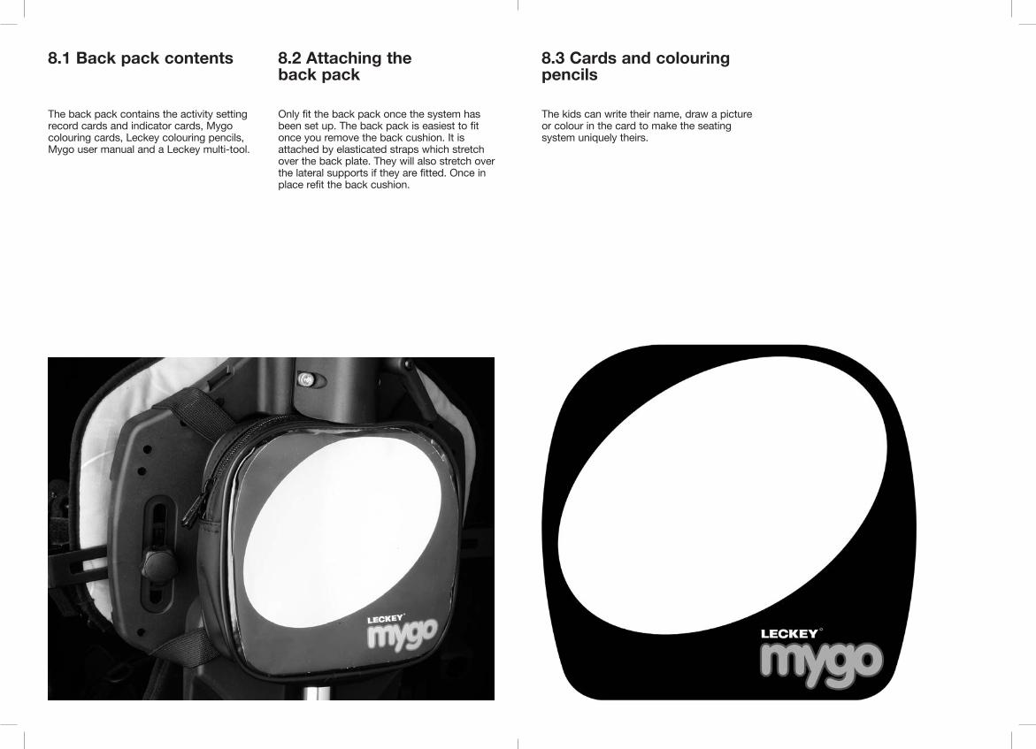
The back pack contains the activity settingrecord cards and indicator cards, Mygo colouring cards, Leckey colouring pencils, Mygo user manual and a Leckey multi-tool.
Only fit the back pack once the system has been set up. The back pack is easiest to fit once you remove the back cushion. It is attached by elasticated straps which stretch over the back plate. They will also stretch over the lateral supports if they are fitted. Once in place refit the back cushion.
8.1 Back pack contents 8.2 Attaching the back pack
8.3 Cards and colouring pencils
The kids can write their name, draw a picture or colour in the card to make the seating system uniquely theirs.

8.4 Activity Setting Record Cards and indicator cards
The indicator card contains stickers which can be applied to the clear strip on the side of the back adjuster. They are designed to indicate the preferred position or back angle for different activities.
The activity setting record cards are used to list the different activities the therapist wishes to carry out in class, or at home. They will describe the new setting and the nature & duration of the activity.
The back pack contains small components which could present a choking hazard to small children. Always check that the zip is closed.
Users should not be left unattended at any time whilst using Leckey equipment.
Fittingthe cushions
9We suggest the cushions are fitted in the following order:
1. Femoral cushions (if applicable)2. Seat base cushion3. Sacral cushion4. Pelvic belt5. Hip laterals6. Trunk harness7. Backrest8. Laterals9. Shoulder support10. Chest harness11. Kneepads12. Headrest

9.1 Femoral cushions (Size 1 only)
Slide a femoral cushion onto each of the femoral supports and stick them together in the centre using Velcro. The cushions should be fitted before the seat base cushion and applies to Size 1 only.
9.2 One piece seat base cushion
The seat base cushion can be attached by simply setting it in place, then pressing down to locate the back snap fastener (A). To secure further, attach the two side snap fasteners (B). Hook the elastic tabs (C) to the upper leg guide locking lever (D) underneath the seat.
Always check the seat base cushion is secure before placing the child in the seat.
A
B
C
D

9.3 Flexible sacral cushion
The flexible sacral cushion can be attached by sliding it over the plastic tongue, using the fixing snap fastener to secure in place.
9.4 Pelvic harness (Size 1 or Size 2)
The Pelvic Harness is attached by sliding the hip guides (A) into the pockets on the outer face of the harness. It is adjusted to the desired position by securing it to one of the snap fasteners (B) on the adjustable hip guide bracket. The buckle on the tie down strap is clipped into a receiving buckle (C) on either side of the seat base. Finally secure the pelvic harness by attaching the centre plastic buckle (D).
D
C
BA
9.5 Pelvic Cradle (Size 2 only)
9.6 Gluteal Ramp
Fasten the Pelvic Cradle and place on the seat base cushion. It is labelled to indicate the correct orientation. Press Velcro onto the seat base cushion and attach four buckles (A) to secure. There are two buckles at the back of the seat and one on either side.
If a gluteal ramp (B) is required, attach it to the Pelvic Cradle using the velcro side.
A A
B

9.7 Hip laterals
These hip laterals are used with the Pelvic Cradle only. Slide the cushion covers over the hip laterals hardware with the velcro flap to the outside. Wrap the two velcro straps (A) round the bracket and stick onto the velcro pad (B). Close over the flap.
A
B
A
9.8 Trunk harness
With your trunk harness you will receive four adjustable side straps, two shoulder straps and brackets, the bolts, washers and locking nuts. Fix the connecting straps to the backrest before attaching the trunk harness. To attach the connecting straps in the shoulder area of Size 1, slide the bracket into the slot (A) and set at the desired height using the bolts and washers provided.
For Size 2 the shoulder straps should be attached into the shoulder section (B), rather than the backrest.
The remaining four adjustable side straps are attached directly without using brackets, to the receiving holes either side of the backrest (C). Simply attach the trunk harness to the connecting straps. The side straps are adjustable in length to accommodate outdoor clothing.
C C
A
B B

9.9 Backrest cushion
If you have lateral supports fitted to your seat, adjust them to their maximum width before attaching the backrest cushion.
Slide the cushion down over the flexible sacral cushion and secure in place using the four snap fasteners in the backrest moulding. Align the lower fasteners first and snap in place, then secure the top fasteners.
9.10 Lateral support padded cushions
9.11 Shoulder support cushion (if applicable)
To attach the lateral support padded cushions, simply slide the cushions on with the padded side towards the inside of the seat. Feed the plastic buckle through the slot in the cover, then bring the two Velcro fastener straps around the bottom of the moulding and attach them to the Velcro panel as shown. Close over the flap.
First loosen the shoulder support laterals (see section 10). Slide the cushion over the assembly and secure using snap fasteners (A) in four places.
AA
A
A

9.12 Chest harness
The chest harness can be attachedby clipping the male buckle (A) into the female buckle at either side of the lateral supports.
9.13 Kneepads
Attach the kneepads with the snap fasteners (A) to the knee guides on the sides of the upper leg supports.
A
A
9.14 Contoured headrest cushion
To attach the headrest cushion, first place the polypropylene reinforcement between the cushion cover and the headrest assembly. It should not be zipped inside the cushion cover.
Then place the cushion onto the head support. Snap the central fastener and two side fasteners in place. Bring the lower flap under the head support and attach the velcro.

9.15 Flat headrest cushion
Place the cushion on to the head support. Secure the central fastener. Bring the lower flap under the head support and secure with the two remaining fasteners. The headrest lateral covers are attached in the same way as the lateral support padded covers.
Clinical setup for Postural ManagementThe clinical setup of the product should be completed by a technically and clinically competent person who has been trained in the use of the product. Leckey recommend a written record is maintained of all clinical setups for this product.
Set the backrest height, seat depth and footplate height before placing the child in the seat. These can be fine tuned when the child is in the seat.
10

10.1 Pelvic Harness 10.2 Pelvic Cradle
To adjust the depth of the pelvic harness, move the snap fastener to either position (B or C). Adjust the support straps to the required length. Ensure the buckle connects securely in the middle (D). If using the seat outdoors and your child is wearing a coat, position the pelvic harness under the coat.
Always attach the pelvic strap first before making any other adjustments.
The Pelvic Cradle should be flat and open when the user is placed into the Mygo Seating System. All four side and back buckles should be already attached to the seat. First fasten the buckle (A) at the front of the Pelvic Cradle. Then fasten the Velcro (B) at the sides to fit the Pelvic Cradle to the user. Then adjust the front and rear straps (C) and (D) to secure to position the user’s pelvis.
D
A
BC
To set the width of the hip guides loosen the Allen bolts (A), adjust to the desired width and retighten.
C
B
D
10.3 Hip Laterals (with Pelvic Cradle only)
A

10.4 Backrest depth
The backrest depth is adjusted by depressing the popper then sliding the back support tube to the desired position. This is very important as it will ensure the seat will fit the child, both when they are upright and in a recline position.
There are three settings where the popper can be located.
Backrest depth
Position A
Position B
Position C
Size 1 (SD)
270-320mm10.6-12.6 inches
320-370mm12.6-14.6 inches
370-420mm14.6-16.5 inches
Size 2 (SD)
350-390mm13.8-15.4 inches
390-430mm15.4-16.9 inches
430-470mm16.9-18.5 inches
We recommend that you measure the child’s upper leg length to define the required seat depth (SD). To do this measure from the child’s lower back to the back of their knee. Then set the backrest to position A, B or C based on the table below.
This backrest depth should not be adjusted while the child is in the seating system.
C B A
SD
10.5 Backrest height
The overall height of the backrest can be adjusted by loosening the two socket cap bolts, then positioning to the required shoulder height of the user. Once in position the socket cap bolts should be retightened securely. The height can be fine tuned when the user is in the seat.
Use caution when adjusting to minimum setting as fingers could become trapped between moving and static parts.

10.6 Backrest angle
The backrest can be angled by loosening the bolt (A). Select the position you require then retighten the bolt securely. Always ensure the back angle is secure to maintain the desired posture for the child.
The backrest angle can be adjusted with the child in the seat, but always support the backrest with one hand.
Always make sure the bolt is secure as this could cause injury to the child or carer.
There are two angle indicator strips on either side of the back adjuster. We have supplied angle location markers (shown below) on a card. These can be applied to the clear strip on the adjuster tube to indicate the desired positions for various activities such as rest, feeding or play.
The angle indicator strip indicates the angle from the seat cushion to the backrest.
The black and yellow hazard strip on the inner tube indicates the maximum forward or prone position the backrest can be adjusted to.
A
10.7 Adjusting the Dynamic Backrest
To achieve the required amount of dynamic movement loosen the handle (a), slide to the required position and retighten securely. To return the backrest to a static position, loosen the handle (a), slide the backrest strut to the bottom and retighten the handle.
To angle adjust the backrest where a dynamic backrest has been fitted, you use the handle at the base of the backrest. Pull the locking pin (c) and twist and unlock. Lift up the handle (b) and adjust the backrest. Pull the locking pin (c). Ensure that the locking pin is secure.
The range of the backrest angle and the range of dynamic movement are a maximum of 30°, i.e. if the backrest is upright, a full 30° is available on the dynamic system. If the backrest angle is at 10° then only 20° of movement is available with the dynamic backrest and so on.
The backrest must be in the upright position with the dynamic function locked off (i.e. the handle to the lowest position on the backrest supine) and ensure the locking pin (c) is engaged when the seating system is used in transport.

A A
10.8 Adjusting the upper leg supports
The upper leg supports will be set at the minimum position on arrival. Set the depth before placing the child in the seat. Fine adjustment is possible afterwards but is restricted by the user’s weight. To achieve the correct position measure the length from the child’s lower back to the back of their knee.
For Size 1 adjust the supports to the desired position using the locking lever (A) underneath the seat base. To adjust, press the locking button and release. Keep the supports pointing straight forward at this time unless wind sweeping or adduction, abduction must be accommodated, in which case set the angle accordingly using the locking lever again.
The supports can be readjusted once the child has been placed in the chair.
For Size 2, loosen the locking levers under the seat and slide leg support to required position. Keep the supports pointing straight forward at this time unless wind sweeping or adduction, abduction must be accommodated, in which case set the angle accordingly. Retighten bolt. To increase the angle further, remove bolt and move leg angle to wider setting. Insert bolt into second slot (B) and tighten.
B B
10.9 Upper leg guide lateral supports
To adjust the width of the knee supports on Size 1, loosen the bolts (A) on the underside of the leg support. Set to the desired width and retighten. To adjust the width or angle on the lateral supports on Size 2, loosen the bolts (B) from above, move the guides and retighten the bolts.
AA
A A
B

10.10 Footplate height
To set the height of the footplate loosen the bolt (A) on the front of the calf support tube and slide the footplate to the required height and retighten the bolt.
To set the correct height of the footplate measure the distance from the back of the child’s knee to the bottom of their heel.You may have to adjust the angle to achieve the required foot position. To adjust the angle loosen the bolt (B) with the multi-tool, set to the desired angle and retighten. There is a safety popper to indicate maximum safe extension. This can be set with the child in the seat.
Always check the footplate is secure to prevent the user sliding forward and down in the seat which could pose a choking hazard if a chest or trunk harness is attached.
A
B
10.11 Footplate angle adjustment
To set the angle to accommodate plantarflexion or dorsiflexion, simply loosen or tighten the hand knob (A) to select the angle you require.
The footplates can simply flip up to aid transfer.
A
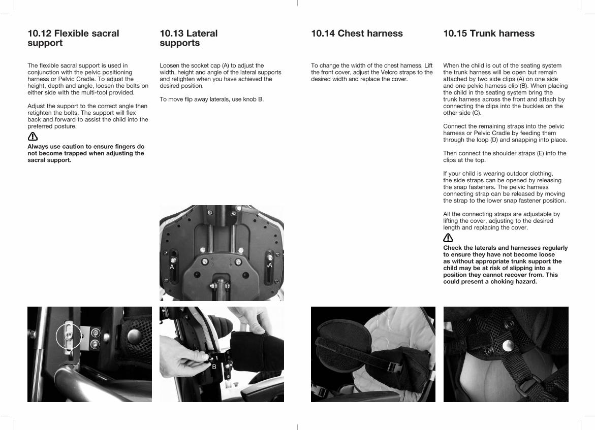
10.12 Flexible sacral support
The flexible sacral support is used in conjunction with the pelvic positioning harness or Pelvic Cradle. To adjust the height, depth and angle, loosen the bolts on either side with the multi-tool provided.
Adjust the support to the correct angle then retighten the bolts. The support will flex back and forward to assist the child into the preferred posture.
Always use caution to ensure fingers do not become trapped when adjusting the sacral support.
10.13 Lateral supports
Loosen the socket cap (A) to adjust the width, height and angle of the lateral supports and retighten when you have achieved the desired position.
To move flip away laterals, use knob B.
B
A A
10.14 Chest harness
To change the width of the chest harness. Lift the front cover, adjust the Velcro straps to the desired width and replace the cover.
10.15 Trunk harness
When the child is out of the seating system the trunk harness will be open but remain attached by two side clips (A) on one side and one pelvic harness clip (B). When placing the child in the seating system bring the trunk harness across the front and attach by connecting the clips into the buckles on the other side (C).
Connect the remaining straps into the pelvic harness or Pelvic Cradle by feeding them through the loop (D) and snapping into place.
Then connect the shoulder straps (E) into the clips at the top.
If your child is wearing outdoor clothing, the side straps can be opened by releasing the snap fasteners. The pelvic harness connecting strap can be released by moving the strap to the lower snap fastener position.
All the connecting straps are adjustable by lifting the cover, adjusting to the desired length and replacing the cover.
Check the laterals and harnesses regularly to ensure they have not become loose as without appropriate trunk support the child may be at risk of slipping into a position they cannot recover from. This could present a choking hazard.

A
AB
D
C
C
E
E
10.16 Adjusting the kneepads
The kneepads can be used as a limiter to help prevent the child from sliding forward in the seat. It can also be used above the knee to prevent the child from raising their foot. To adjust the kneepads lift the front cover adjust the Velcro straps to the desired length and reposition in place. To remove unclip the snap fastener on one side.
10.17 Sandals
To position the user’s feet in the sandals secure the Velcro straps provided so the foot is held in place. The straps should be placed over the bridge of the foot and over the toes. The front strap can be fed through one of two slots on either side of the sandals, depending on the size of the user’s feet (2).
If the child is wearing sandals or light footwear check the straps to make sure the webbing does not irritate the skin.
1
2

10.19 Contoured head support
10.18 Shoulder Support Laterals (Size 2 only)
To adjust the height, depth and angle of the contoured headrest, loosen the hand knobs (A) and when set to the desired position retighten the knobs. Do not remove the headrest while the user is in the seat.
Never use the headrest to force the position of the user’s head.
Always use caution to ensure fingers do not become trapped when adjusting the headrest.
To adjust the angle of the shoulder support laterals, loosen screw A, move laterals to required angle and retighten.
AA
AA
10.21 Armrest adjustment
To adjust the height of the armrest loosen the hand knob (B), set to the desired height and retighten. To adjust the angle, rotate ratchet handle (A) until the desired position has been achieved.
To remove the armrest completely, loosen ratchet handle (C), press popper (D) and lift the armrest.
Always use caution as fingers could become trapped in the slot when adjusting the height.
A
B
C
10.20 Flat headrest with lateral supports
To adjust the height, depth and angle of the flat headrest, adjust using the hand levers (A), as shown on the contoured head support.
To adjust the width of the laterals loosen plastic knob (B), slide to desired position and tighten securely.
B
D

10.23 Grab rail adjustment
To set the depth of the grab rail to suit the child’s reach, loosen knob (A), adjust to the required depth and then re-tighten.
Do not adjust the horizontal bars beyond the moulding, except when you are removing the tray.
A
10.22 Tray Adjustment
The height and angle of the tray are set by adjusting the armrests as detailed above. To remove or adjust the depth of the tray loosen the knobs (A) under the armrest, set to the desired position and re-tighten securely.
Always use caution to ensure the child’s hands or arms do not become trapped when inserting the tray.
Never use the tray to steer or push the chair.
Do not place objects, hotter than 40 degrees Celsius on the tray.
Please note that the tray is for the use of the user only. Do not lean or place objects on the tray, greater than 8kgs (17.6lbs).
A
Frequent adjustment for daily use (therapists/ carers/parents)Parents and carers should be shown how to make frequent adjustments and be made aware of the safety checks in Section 6 by a technically and clinically competent person who has been trained in the use of the product. Leckey recommend that a written record is maintained of all parents and carers who have been trained in the use of this product.
11

11.1 Transferring your child into and out of the seat
Before transferring the child into the seat carry out the daily product inspection as outlined in section 13 of this user manual. Adjust the seat to a comfortable height to facilitate transfer. Lock all the castors, ensuring that they are facing outwards to maximise product stability. Make sure the safety buckle on the chest harness is released and is out of the way to facilitate transfer.
If the seat has flip-away thoracic laterals, first move these out of the way using knob A.
Unclip the pelvic harness or Pelvic Cradle in the middle, undo the side velcro of the Pelvic Cradle and allow the harness to open out to facilitate transfer. Lastly, if sandals are fitted, open the straps. You are now ready to transfer or hoist the child into the seat.
The pelvic harness and Pelvic Cradle are fastened using the middle buckle, and side velcro (in the case of the Pelvic Cradle).
Always secure the pelvic harness or Pelvic Cradle first before fastening other buckles or harnesses. Adjust the harness so the child cannot slide or creep forward in the seat.
A
Pelvic Cradle (Size 2 only)
CC
11.2 Adjusting the pelvic harness or Pelvic Cradle
The correct positioning and tensioning of the pelvic harness or Pelvic Cradle is key to a child’s postural management, affecting their comfort and ability to carry out activities. Please consult with your therapist to ensure the harness is positioned correctly and that the straps are tensioned appropriately.
To tension the pelvic harness straps and pads around the child pull the centre strap (A). Pull the two side straps up to fine tune the pelvic position and adjust (B) the height of the pads on the hips.
To tension the Pelvic Cradle use the 4 side straps (C) and the velcro tabs (D).
If using the seat outdoors and your child is wearing a coat, position the pelvic harness or Pelvic Cradle under the coat.
Pelvic harness (Size 1 or Size 2)
A
B
If the child is active or has extensor spasms check the Pelvic harness or Pelvic Cradle is secure after each spasm to ensure the child is safe and cannot slide forward in the seat.
Always fasten the centre buckle on the pelvic harness or Pelvic Cradle before making any other adjustments.
C
D
11.3 Chassis
The Mygo Seat is designed to fit onto a range of chassis. This user manual shows the correct and safe use of the seating system with the Leckey Hi-low chassis. For all other chassis or bases please refer to the manufacturer’s handbook.
To prepare the Hi-low chassis for the seating system we recommend that you raise the chassis to a comfortable working height by pressing the foot lever at the rear of the chassis or by pressing the up button on the handset of the powered option.
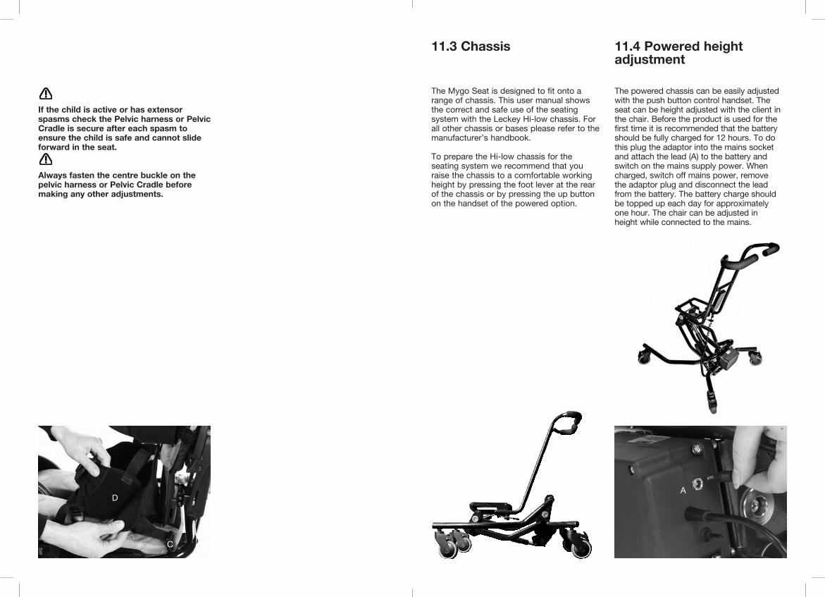
11.4 Powered height adjustment
The powered chassis can be easily adjusted with the push button control handset. The seat can be height adjusted with the client in the chair. Before the product is used for the first time it is recommended that the battery should be fully charged for 12 hours. To do this plug the adaptor into the mains socket and attach the lead (A) to the battery and switch on the mains supply power. When charged, switch off mains power, remove the adaptor plug and disconnect the lead from the battery. The battery charge should be topped up each day for approximately one hour. The chair can be adjusted in height while connected to the mains.
A

Always keep the locking pin engaged when you are not adjusting the chassis. This will prevent the foot pedal being operated accidentally.
For children over the weight of 27kg (60lbs), raising the manual chassis is a 2 person lift (UK lifting and handling regulations).
Always use caution as hands could become trapped when height adjusting the base.
11.5 Height Adjustment – Hi-low chassis
You can carry out this adjustment with the child in the chair. To adjust the height of the Hi-low chassis, press the foot lever at the rear of the chassis, or press the up button on the handset of the powered option whilst holding the push handle. Once you remove your foot from the pedal or your thumb from the handset, the seat will be fixed at the chosen height.
For safety, the height adjustment pedal on the chassis can be locked by engaging the pull pin (C) on the right hand side of the pedal. To unlock, pull the pin out and rotate 90 degrees, the pedal can then be operated. The locking pin (C) should be kept in the locked position when you are not adjusting the chassis.
c
11.6 Tilt-in-space
The tilt-in-space can be angled while the user is in the seat. Before you adjust the tilt-in-space angle of the seat, always ensure the pelvic harness is secured preventing the user from sliding forward in the seat.
To adjust the tilt angle press the lever under the seat base. Once you have selected the angle you require, by simply removing your hand from the lever, the chair will be locked in position. The tilt-in-space should be locked off while the user is in the seat. To lock the lever twist the pull pin to the right hand side of the lever and the pin will pop into position. You may have to lift the lever slightly to allow it to lock. To unlock pull the pin out and rotate 90 degrees, the lever can then be operated.
Always keep the tilt-in-space lever in the locked position to prevent accidental actuation of the lever which could cause the seat unit to jolt and possibly cause injury to the child.
Please use handle bars when operating tilt-in-space.
Always check with your therapist that the use of tilt-in-space will not cause any obstructions to the child’s airways.
Lever
Locking pin

11.7 Adjusting the Dynamic Backrest
To return the backrest to a static position, loosen the handle (a), slide the backrest strut to the bottom, retighten the handle.
The backrest must be in the upright position with the dynamic function locked off (i.e. the handle to the lowest position on the backrest supine) and ensure the locking pin (c) is engaged when the seating system is used in transport.
11.8 Chest and Trunk Harness adjustment
If the child requires chest support as part of their postural support programme, the seat will be fitted with rigid laterals or a combination of laterals, chest harness and trunk harness. These may need to be adjusted on a daily basis to accommodate differences in clothing.
Always check with your therapist as to the optimum positioning and tensioning of the straps and support items for the child.
To change the width of the chest harness, lift the front cover, adjust the Velcro straps and set to the desired width. When the correct width has been achieved replace the cover.
Please refer to section 10 for specific guidance on adjusting the trunk harness.
Always make sure the plastic buckles are fully engaged when using the chest harness.
Check the harness and laterals are secure to ensure the child is safe and cannot slide forward in the seat as this may restrict their breathing.
A
11.9 Sandals
To position the user’s feet in the sandals, secure the Velcro straps provided so the foot is held in place. The straps should be placed over the bridge of the foot and over the toes. The front strap can be fed through one of two slots on either side of the sandals, depending on the size of the user’s feet (2).
If the child is wearing sandals or light footwear check the straps to make sure the webbing does not irritate the skin.
11.10 Tray adjustment
The activity tray can be used for a range of functions and its position can be fine tuned to suit the user and the activity whether it is for fun, education or feeding. The tray is attached to the seat by inserting the tray tubes through the centre of the armrest. Once the tray is located in the position the knob (A) should be tightened securely.
Adjust the armrests to set the height and angle of the tray.
A
B
C
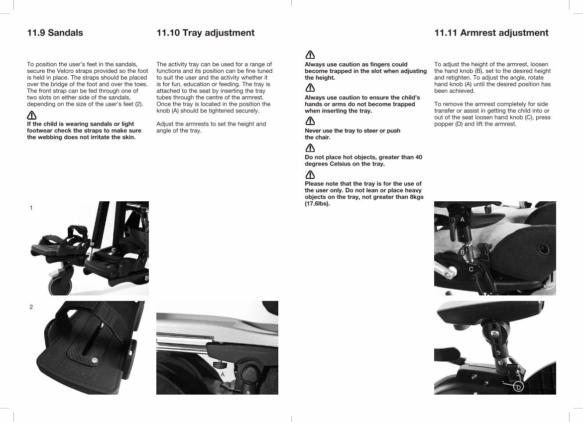
11.11 Armrest adjustment
To adjust the height of the armrest, loosen the hand knob (B), set to the desired height and retighten. To adjust the angle, rotate hand knob (A) until the desired position has been achieved.
To remove the armrest completely for side transfer or assist in getting the child into or out of the seat loosen hand knob (C), press popper (D) and lift the armrest.
Always use caution as fingers could become trapped in the slot when adjusting the height.
Always use caution to ensure the child’s hands or arms do not become trapped when inserting the tray.
Never use the tray to steer or push the chair.
Do not place hot objects, greater than 40 degrees Celsius on the tray..
Please note that the tray is for the use of the user only. Do not lean or place heavy objects on the tray, not greater than 8kgs (17.6lbs).
D
1
2
11.12 Grab rail adjustment
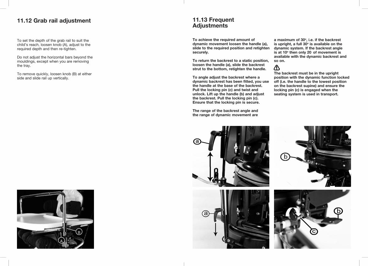
To set the depth of the grab rail to suit the child’s reach, loosen knob (A), adjust to the required depth and then re-tighten.
Do not adjust the horizontal bars beyond the mouldings, except when you are removing the tray.
To remove quickly, loosen knob (B) at either side and slide rail up vertically.
A
B
11.13 Frequent Adjustments
To achieve the required amount of dynamic movement loosen the handle (a), slide to the required position and retighten securely.
To return the backrest to a static position, loosen the handle (a), slide the backrest strut to the bottom, retighten the handle.
To angle adjust the backrest where a dynamic backrest has been fitted, you use the handle at the base of the backrest. Pull the locking pin (c) and twist and unlock. Lift up the handle (b) and adjust the backrest. Pull the locking pin (c). Ensure that the locking pin is secure.
The range of the backrest angle and the range of dynamic movement are
a maximum of 30o, i.e. if the backrest is upright, a full 30o is available on the dynamic system. If the backrest angle is at 10o then only 20 of movement is available with the dynamic backrest and so on.
The backrest must be in the upright position with the dynamic function locked off (i.e. the handle to the lowest position on the backrest supine) and ensure the locking pin (c) is engaged when the seating system is used in transport.
12 Cleaning & Care Information
How to MaintainWhen cleaning we recommend that you use only warm water and a non-abrasive detergent. Never use organic solvents or dry cleaning fluids.
Upholstery and fabrics1. The cushion covers can be removed, machine washed at 40ºC and tumble dried at a low temperature.
Please remove the foam from the following covers before washing:HeadrestShoulder supportBackrest cushionSeat base cushion
All other soft upholstery can be placed into the washing machine intact, after removing bolts and fastenings.
2. The upholstery and fabrics can also be cleaned by hand whilst in place. When cleaning we recommend that you use only warm water and a non-abrasive detergent.
3. Staining should be removed as quickly as possible with absorbent cloth, towels or a sponge. Routine soap and warm water sponging is effective for ordinary soiling and minor spills. Be careful not to over wet the fabric as this will cause the staining to spread.
4 Antiseptic cleaning agents can be used on more stubborn stains. These may require a safe solvent such as Isopropyl Alcohol or Mineral Spirit. A half cup of household bleach to 5 litres of water can also be used as a useful disinfectant.
5. The pelvic and trunk harnesses can be machine washed at 40 Deg C. Make sure all bolts and fasteners are removed first as they may cause damage to your washing machine. Store these in a safe place and out of reach from children.
6 Always ensure the product is dry before use.
Metal and plastic components1. Soap and water or antibacterial spray can be used for daily cleaning.
2. For deep cleaning a low pressure steam cleaner can be used.
3. Do not use solvents to clean plastic or metal components.
4. Make sure the product is dry before use.
13 Daily Product Inspection
(Therapists, parents & carers)We recommend that daily visual checks of the equipment are carried out by therapists, carers or parents to ensure the product is safe for use. The recommended daily checks are detailed below.
1. Check that there is no lateral movement or wobble in any of the moving parts. Ensure all adjustment knobs and bolts are in place and secure.
2. Check all upholstery and Velcro for signs of wear and tear.
3. Check all castors are moving freely and lock securely.
4. Ensure the handle and locking pin on the seat interface plate is fully engaged and the seat unit is securely fixed onto the chassis.
5. Ensure the pelvic harness is fully secured around the user and they cannot slide or creep forward in the seat.
6. Ensure the footplate is attached securely.
If in any doubt to the continued safe use of your Leckey product or if any parts should fail, please cease using the product and contact our Customer Care Team or your local dealer as soon as possible.

14 Annual Product Inspection
(Therapist, Technician, VIDA Product Specialist, Dealer)Leckey recommend that each product should be subject to a detailed inspection at least once a year and every time the product is reissued for use. This inspection should be carried out by a technically competent person who has been trained in the use of the product and should include the following checks as a minimum requirement.
1. Check that there is no lateral movement or wobble in any of the moving parts. Ensure all adjustment knobs and bolts are in place and secure.
2. Check all ratchet handles, knobs, nuts, bolts and plastic buckles are in place, replacing any missing items. Paying particular attention to the following items;> Head support locking bolts. > Backrest height and angle adjustments bolts.> Seat depth adjustment bolts.> Pelvic harness / hip guide attachment bolts.> Footrest height and angle adjustment.
3. Check the chassis height adjustment mechanism is working properly. If the chassis is foot pedal operated ensure the seat height doesn’t change when the pedal is released. Also, check that the locking pin engages securely to prevent accidental height adjustment of the chassis.
4. Adjust the seat to its maximum range of tilt-in-space and ensure that the locking lever locks the seat out securely at varying point in this range.
5. Check that where the seat and chassis join there is no visible wear and tear on the metal components.
6. Lift the base to check each castor individually. Make sure they are moving freely and remove any dirt from the rubber wheels. Check that the brakes lock the wheels securely.
7. Visually check the structure of the product paying attention to weld points on the frame ensuring there are no signs of fatigue or cracking around the welds.
8. Leckey recommend that a written record is maintained of all annual product inspections.
If in any doubt to the continued safe use of your Leckey product or if any parts should fail, please cease using the product and contact our Customer Care Team or your local dealer as soon as possible.
15 Re-issuing Leckey Products
Most Leckey products are assessed and ordered to meet the needs of an individual user. Before reissuing a product we recommend that the therapist prescribing the product has carried out an equipment compatibility check for the new user and has ensured that the product being re-issued contains no modifications or special attachments.
A detailed technical inspection should be carried out on the product prior to re-issuing. This should be carried out by a technically competent person who has been trained in the use and inspection of the product. Please refer to section 14 for the required checks to be carried out.
Ensure the product has been cleaned thoroughly in accordance with section 12 of this manual.
Ensure a copy of the user manual is supplied with the product. A copy can be downloaded from our website www.leckey.com
Leckey recommend that a written record is maintained of all product inspections carried out during the reissue of the product.
If in any doubt to the continued safe use of your Leckey product or if any parts should fail, please cease using the product and contact our Customer Care Team or your local dealer as soon as possible.
16 Product Servicing
Servicing of all Leckey products should only be carried out by technically competent persons who have been trained in the use of the product.
All international service enquiries should be directed to the appropriate Leckey distributor who will be delighted to assist you. For further information on Leckey distributors please visit our website www.leckey.com

17 Technical Information
Product and Accessory Codes117-610 Size 1 Seat Shell 137-600 Size 2 Seat Shell117-1851* Size 1 Seat Cushion and Covers117-2851* Size 2 Seat Cushion and Covers
Chassis102-2753 Hi-Low Chassis Foot Pedal 102-2754 Hi-Low Chassis Powered117-780 Mygo on Mobility Base (UK only)117-784 Mygo on Stroller Base
Mobility Interface Options117-775 Interface A 117-726 Interface B 117-727 Interface C
Accessories117-801 Pelvic Harness - Small117-802 Pelvic Harness - Medium133-728 Pelvic Cradle137-632 Hip Laterals117-1777 Size 1 Armrests117-2777 Size 2 Armrests117-1776 Size 1 Footplates117-2776 Size 2 Footplates152-1600 Size 1 Sandals152-2600 Size 2 Sandals152-3600 Size 3 Sandals117-803 Rigid Laterals with Black Covers117-837 Flip-away Laterals with Black Covers137-621 Shoulder Support Hardware137-801* Shoulder Support Cushion and Cover117-757 Chest Harness120-799 Trunk Harness - Small120-757 Trunk Harness - Medium117-761 Trunk Harness - Large117-765 Kneepads117-851-05 Flat Headrest and Cushion120-893-05 Flat Headrest Laterals and Covers137-699-05 Contoured Headrest and Cushion117-724 Tray117-769 Grab Rail117-791 Obliquity KitAH01 Pair of Small Ankle Huggers AH02 Pair of Medium Ankle Huggers
*Add Colour Option+07 Orange, +08 Blue, +09 Pink, +06 Grey
Mygo seat dimensions
Size
Age (approx)
Codes
User Weight
User Height
Seat Width
Footplate:AbductionAdductionPlantarflexion/Dorsiflexion
1
3 - 10
117-610
Min 18kg / 40lbsMax 50kg / 110lbsMin 105cm / 41 inchesMax 150cm / 59 inchesMin 200mm / 8 inchesMax 325mm / 13 inchesMin 270mm / 10.6 inchesMax 420mm / 16.5 inchesMin 90mm / 3.5 inchesMax 110mm / 4.3 inches
8º12º10º
Seat Depth
Knee Width
Chest Width
Backrest Height
Backrest Angle:Prone Recline
Seat to Sandal
Top of Seat to Floor
Armrest Height
Tray Size
Seat Unit Weight
Min 170mm / 6.7 inchesMax 270mm / 10.6 inchesMin 360mm / 14.2 inchesMax 470mm / 18.5 inches
Min 215mm / 8.5 inchesMax 350mm / 13.8 inches
10º25º
Min 360mm / 14.2 inchesMax 700mm / 27.5 inchesMin 160mm / 6.3 inchesMax 210mm / 8.3 inches550 x 480mm21.6 inches x 18.9 inches
10kg / 22lbs
2
8 - 14
137-600
Min 18kg / 40lbsMax 50kg / 110lbsMin 127cm / 50 inchesMax 168cm / 66 inchesMin 220mm / 8.7 inchesMax 345mm / 13.6 inchesMin 350mm / 13.8 inchesMax 470mm / 18.5 inchesMin 120mm / 4.7 inchesMax 470mm / 18.5 inches
8º20º10º
Min 170mm / 6.7 inchesMax 270mm / 10.6 inchesMin 460mm / 18.1 inchesMax 570mm / 22.4 inches
Min 315mm / 12.4 inchesMax 470mm / 18.5 inches
10º25º
Min 360mm / 14.2 inchesMax 700mm / 27.5 inchesMin 210mm / 8.3 inchesMax 260mm / 10.2 inches550 x 480mm21.6 inches x 18.9 inches
14.5kg / 32lbs
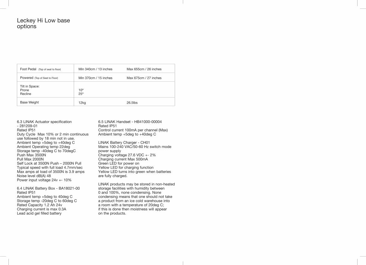
Leckey Hi Low base options
6.3 LINAK Actuator specification - 281209-01 Rated IP51Duty Cycle Max 10% or 2 min continuous use followed by 18 min not in use.Ambient temp +5deg to +40deg CAmbient Operating temp 22degStorage temp -40deg C to 70degCPush Max 3500NPull Max 2000NSelf Lock at 3500N Push – 2000N PullTypical speed with full load 4.7mm/secMax amps at load of 3500N is 3.9 ampsNoise level dB(A) 48Power input voltage 24v +- 10%
6.4 LINAK Battery Box - BA18021-00Rated IP51Ambient temp +5deg to 40deg CStorage temp -20deg C to 60deg CRated Capacity 1.2 Ah 24vCharging current is max 0.3ALead acid gel filled battery
6.5 LINAK Handset - HB41000-00004Rated IP51Control current 100mA per channel (Max)Ambient temp +5deg to +40deg C
LINAK Battery Charger - CH01Mains 100-240 VAC/50-60 Hz switch mode power supplyCharging voltage 27.6 VDC +- 2%Charging current Max 500mAGreen LED for power onYellow LED for charging functionYellow LED turns into green when batteries are fully charged.
LINAK products may be stored in non-heated storage facilities with humidity between 0 and 100%, none condensing. None condensing means that one should not take a product from an ice cold warehouse into a room with a temperature of 20deg C; if this is done then moistness will appear on the products.
Foot Pedal (Top of seat to floor)
Powered (Top of Seat to Floor)
Tilt in Space:ProneRecline
Base Weight
10º25º
12kg 26.5lbs
Min 370cm / 15 inches Max 675cm / 27 inches
Min 340cm / 13 inches Max 655cm / 26 inches

LS151-07
24 hour postural care for babies, kids & adults. Sleeping, Sitting, Standing, Walking, Moving, Bathing, Toileting.
VIDA Global19C Ballinderry Road,Lisburn, BT28 2SANorthern Ireland,United Kingdom
T: 028 9260 0750F: 028 9260 0799E: [email protected]: vidaglobal.co.uk