Embed Size (px)
Citation preview
AP/AD
HNB/G
USB/G
FAB/G
FGB/G
FVB
FWB/G
FHB
FLB
AB
AG
CHB/G
MXB/G
SAB/SVB
HVB/HVL
Fordry air
NP/NAP/NVP
PD/FAD/PJ
CVE/CVSE
CPE/CPD
Customorder
Medicalanalysis
Other G.P.systems
APK/ADK
Explosionproof
Mot
or d
riven
2, 3
por
t bal
l val
ve
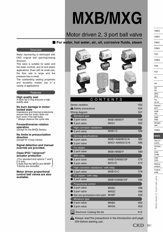
Motor driven 2, 3 port ball valve
MXB/MXG
Water hammering is eliminated with CKD original ball opening/closing structure. This valve is suitable for water and hot water controls, and oil and steam applications. Even with its small size, the flow rate is large and the pressure loss is small. The outstanding sealing properties and durability enable use in a variety of applications.
Overview
High quality sealA back-up O ring ensures a high quality seal.
No burn damage in motor-locked stateImpedance and thermal protections ensure that the motor does not burn even if the ball locks.* Always observe the cycle rate.
Forward/reverse rotation operation(except for the MH 4 Series)
No limits to pressurization direction(except for 3-way valves)
Signal detection and manual override are provided.
Class IPX3 "rainproof" actuator protection
Motor driven proportional control ball valves are also available.
For standard and options T and K only.Note that the MH 4 and MHBP Series are excluded.
Features
C O N T E N T S
Always read the precautions in the Introduction and page554 before starting use.
Series variation 552
Safety precautions 554
Wiring diagram 557
Standard type
2 port valve
3 port valve
High corrosion resistance
2 port valve
Oil-free specifications
2 port valve
3 port valve
For steam
2 port valve
With relay
2 port valve
3 port valve
High corrosion resistance / with relay
2 port valve
For steam / with relay
2 port valve
Proportional control
2 port valve
3 port valve
Motor valve type temperature control system
Miniature type
2 port valve
3 port valve
Electronic Catalog file list 612
MXB1/MXB1FMXG1
MXB1-C
MXB1-N/MXB1D-NMXG1-N/MXG1D-N
MSB1/MSB1F
MXB1D/MXB1DFMXG1D
MXB1D-C
MSB1D/MSB1DF
MXBCMXGCMHBP
MHB4MHG4
558562
566
582586
590
570574
578
594
598598608
602602
BG
BG
For water, hot water, air, oil, corrosive fluids, steam
551
552
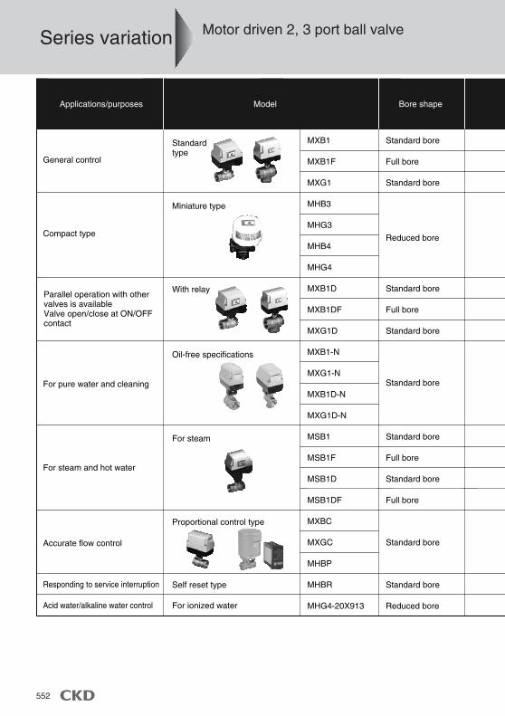
Model Bore shapeApplications/purposes
General control
MXB1
MXB1F
MXG1
MHB3
MHG3
MHB4
MHG4
MXB1D
MXB1DF
MXG1D
MXB1-N
MXG1-N
MXB1D-N
MXG1D-N
MSB1
MSB1F
MSB1D
MSB1DF
MXBC
MXGC
MHBP
MHBR
MHG4-20X913
Standard bore
Full bore
Standard bore
Reduced bore
Standard bore
Full bore
Standard bore
Standard bore
Standard bore
Full bore
Standard bore
Full bore
Standard bore
Standard bore
Reduced bore
Miniature type
With relay
For steam
Proportional control type
Self reset type
For ionized water
Compact type
Oil-free specifications
For pure water and cleaning
For steam and hot water
Accurate flow control
Responding to service interruption
Acid water/alkaline water control
Parallel operation with other valves is availableValve open/close at ON/OFF contact
Standardtype
Series variation Motor driven 2, 3 port ball valve
553
AP/AD
HNB/G
USB/G
FAB/G
FGB/G
FVB
FWB/G
FHB
FLB
AB
AG
CHB/G
MXB/G
SAB/SVB
HVB/HVL
Fordry air
NP/NAP/NVP
PD/FAD/PJ
CVE/CVSE
CPE/CPD
Customorder
Medicalanalysis
Other G.P.systems
APK/ADK
Explosionproof
Mot
or d
riven
2, 3
por
t bal
l val
ve
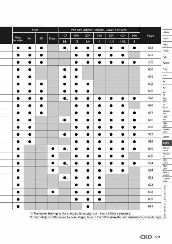
Fluid Port size (Upper: Nominal, Lower: Port size)
Water,hot water
Air Oil Steam10A
3/8 1/2 3/4 1 11/4 11/2 2
15A 20A 25A 32A 40A 50A Page
558
558
562
636
636
602
602
570
570
574
582
586
582
586
590
590
594
594
598
598
608
636
823
*1: The model belongs to the standard bore type, but it has a full bore structure. *2: For details on differences by bore shape, refer to the orifice diameter and dimensions on each page.
*1
*1
*1
*1
*1
554
1
2
2
3
Fluid viscosityGenerally, the valve can be used with a fluid viscosity of up to 500 mm2/s. However, the properties may differ according to the fluid type, so consult with CKD.
Fluid propertiesIron rust and dirt, etc., in the fluid can cause operation faults or leaks and reduce product performance.
CAUTION
Design & Selection
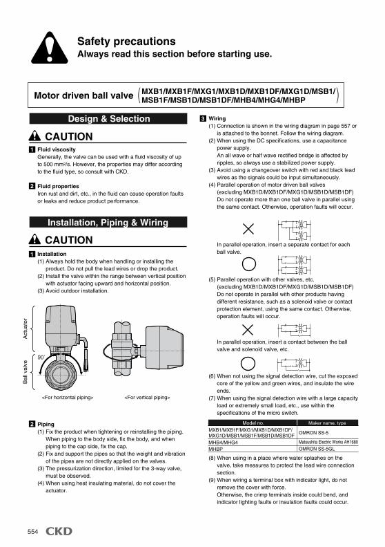
1 Installation(1) Always hold the body when handling or installing the
product. Do not pull the lead wires or drop the product. (2) Install the valve within the range between vertical position
with actuator facing upward and horizontal position. (3) Avoid outdoor installation.
Piping(1) Fix the product when tightening or reinstalling the piping.
When piping to the body side, fix the body, and when piping to the cap side, fix the cap.
(2) Fix and support the pipes so that the weight and vibration of the pipes are not directly applied on the valves.
(3) The pressurization direction, limited for the 3-way valve, must be observed.
(4) When using heat insulating material, do not cover the actuator.
CAUTION
Installation, Piping & Wiring
MXB1/MXB1F/MXG1/MXB1D/MXB1DF/MXG1D/MSB1/MSB1F/MSB1D/MSB1DF/MHB4/MHG4/MHBP
M
M
M
M
M
M
Model no.
MHB4/MHG4MHBP
OMRON SS-5
Matsushita Electric Works AH1680OMRON SS-5GL
Maker name, type
Wiring(1) Connection is shown in the wiring diagram in page 557 or
is attached to the bonnet. Follow the wiring diagram. (2) When using the DC specifications, use a capacitance
power supply. An all wave or half wave rectified bridge is affected by ripples, so always use a stabilized power supply.
(3) Avoid using a changeover switch with red and black lead wires as the signals could be input simultaneously.
(4) Parallel operation of motor driven ball valves(excluding MXB1D/MXB1DF/MXG1D/MSB1D/MSB1DF)Do not operate more than one ball valve in parallel using the same contact. Otherwise, operation faults will occur.
(5) Parallel operation with other valves, etc.(excluding MXB1D/MXB1DF/MXG1D/MSB1D/MSB1DF)Do not operate in parallel with other products having different resistance, such as a solenoid valve or contact protection element, using the same contact. Otherwise, operation faults will occur.
(8) When using in a place where water splashes on the valve, take measures to protect the lead wire connection section.
(9) When wiring a terminal box with indicator light, do not remove the cover with force. Otherwise, the crimp terminals inside could bend, and indicator lighting faults or insulation faults could occur.
(6) When not using the signal detection wire, cut the exposed core of the yellow and green wires, and insulate the wire ends.
(7) When using the signal detection wire with a large capacity load or extremely small load, etc., use within the specifications of the micro switch.
In parallel operation, insert a separate contact for each ball valve.
In parallel operation, insert a contact between the ball valve and solenoid valve, etc.
Motor driven ball valve
MXB1/MXB1F/MXG1/MXB1D/MXB1DF/MXG1D/MSB1/MSB1F/MSB1D/MSB1DF
Act
uato
rB
all v
alve
Safety precautionsAlways read this section before starting use.
90˚
<For horizontal piping> <For vertical piping>
555
AP/AD
HNB/G
USB/G
FAB/G
FGB/G
FVB
FWB/G
FHB
FLB
AB
AG
CHB/G
MXB/G
SAB/SVB
HVB/HVL
Fordry air
NP/NAP/NVP
PD/FAD/PJ
CVE/CVSE
CPE/CPD
Customorder
Medicalanalysis
Other G.P.systems
APK/ADK
Explosionproof
Mot
or d
riven
2, 3
por
t bal
l val
ve
1
1
2
Cycle rateAlways observe the cycle rate. Otherwise, the thermal protector could operate and stop the valve. In the locked state, a continuously energized state could be created placing a load on the gears and coils. Turn the power off immediately, and eliminate the problem. Continuing use could result in operation faults or reduce the durability.
Signal switchoverSwitch the valve signal so that the next signal is input after the valve operation ends. If operation is stopped or if the signal is switched midway, operation faults could occur and the service life could be shortened.
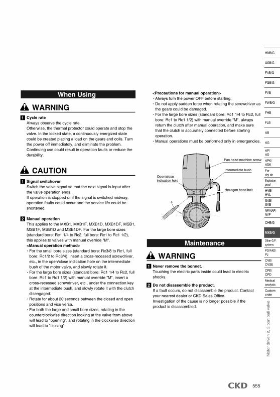
Manual operationThis applies to the MXB1, MXB1F, MXB1D, MXB1DF, MSB1, MSB1F, MSB1D and MSB1DF. For the large bore sizes (standard bore: Rc1 1/4 to Rc2, full bore: Rc1 to Rc1 1/2), this applies to valves with manual override "M". <Manual operation method>· For the small bore sizes (standard bore: Rc3/8 to Rc1, full
bore: Rc1/2 to Rc3/4), insert a cross-recessed screwdriver, etc., in the open/close indication hole on the intermediate bush of the motor valve, and slowly rotate it.
· For the large bore sizes (standard bore: Rc1 1/4 to Rc2, full bore: Rc1 to Rc1 1/2) with manual override "M", insert a cross-recessed screwdriver, etc., under the connection key at the intermediate bush, and slowly rotate it with the clutch disengaged.
· Rotate for about 20 seconds between the closed and open positions and vice versa.
· For both the large and small bore sizes, rotating in the counterclockwise direction looking at the valve from above will lead to "opening", and rotating in the clockwise direction will lead to "closing".
WARNING
CAUTION
When Using
1 Never remove the bonnet. Touching the electric parts inside could lead to electric shocks.
2 Do not disassemble the product. If a fault occurs, do not disassemble the product. Contact your nearest dealer or CKD Sales Office. Investigation of the cause is no longer possible if the product is disassembled.
WARNING
Maintenance
<Precautions for manual operation>· Always turn the power OFF before starting. · Do not apply sudden force when rotating the screwdriver as
the gears could be damaged. · For the large bore sizes (standard bore: Rc1 1/4 to Rc2, full
bore: Rc1 to Rc1 1/2) with manual override "M", always return the clutch after manual operation, and make sure that the clutch is accurately connected before starting operation.
· Manual operations must be performed only in emergencies.
Pan head machine screw
Intermediate bush
Hexagon head bolt
Open/closeindication hole
556
1
2
3
4
Power supplySelect the power supply allowing for a sufficient capacity (50 W class is recommended). Do not use a full wave rectified bridge as it is affected by ripples or zero voltage, etc. Instead, use a stabilized power supply.
Control methodsUse a controller or thermostat having a PID function, and keep the energizing frequency at 10% or less. When using for ON/OFF control or control with a high energizing frequency, the service life will be shortened, and the thermal protector could be activated due to motor heating. This will temporarily shut off the motor power and prevent correct operations. Lowering the energizing frequency will allow the service life of the entire device to be lengthened, so carefully consider the control methods and energizing frequency.
Service lifeThe product's service life will differ greatly according to the operation. However, as a guide, the life is approx. 12 to 18 months when used with an energizing frequency of 10% for eight hours a day.
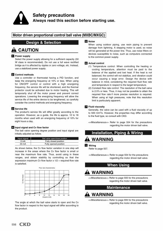
Input signal and Cv flow factorThe ball valve opening degree position and input signal are initially adjusted as follow.
As shown below, the Cv flow factor variation in one step will increase in the areas where the Cv flow factor is small or near the maximum flow rate. Thus, avoid using in these ranges, and obtain stability by controlling so that the expression maximum Cv flow factor x 1/2 = required flow rate is satisfied.
The angle at which the ball valve starts to open and the Cv flow factor in respect to the input signal will differ according to the product.
Motor driven proportional control ball valve (MXBC/MXGC)
CAUTION
Design & Selection
1
5
6
7
<<Miscellaneous>> Refer to page 555 for the precautions regarding the motor driven ball valve.
NoiseWhen using outdoor piping, use resin piping to prevent damage from lightning. A stepping motor is used, so noise will be generated at the power line. Thus, use noise filters on devices susceptible to noise, such as computers connected to the common power supply.
Actual control(1) Temperature control: When controlling the heating or
cooling temperature, attention must be paid to the balance of the applied and lost heat. If the heat is not balanced, the control will not stabilize, and vibration could occur causing a large error. Design the device with balance in mind, considering the required fluid flow rate and temperature in respect to the target temperature.
(2) Constant flow rate control: The resolution of the ball valve is 2.5% or less. Thus, it may not be possible to attain the required flow rate if more precise resolution is required. When using at high pressures, note that this resolution limit is particularly apparent.
Fluid viscosityGenerally, the valve can be used with a fluid viscosity of up to 500 mm2/s. However, the properties may differ according to the fluid type, so consult with CKD.
<<Miscellaneous>> Refer to page 554 for the precautions regarding the motor driven ball valve.
WARNING
When Using
<<Miscellaneous>> Refer to page 555 for the precautions regarding the motor driven ball valve.
WARNING
Maintenance
WiringRefer to page 557.
<<Miscellaneous>> Refer to page 554 for the precautions regarding the motor driven ball valve.
WARNING
Installation, Piping & WiringInput signal
0 mA20 mA
Fully closed positionFully opened position
Ball valve open/close position
Ampere (mA)
Flow rate characteristics
2018161412108640
Cv
flow
fact
or
Safety precautionsAlways read this section before starting use.
557
AP/AD
HNB/G
USB/G
FAB/G
FGB/G
FVB
FWB/G
FHB
FLB
AB
AG
CHB/G
MXB/G
SAB/SVB
HVB/HVL
Fordry air
NP/NAP/NVP
PD/FAD/PJ
CVE/CVSE
CPE/CPD
Customorder
Medicalanalysis
Other G.P.systems
APK/ADK
Explosionproof
Mot
or d
riven
2, 3
por
t bal
l val
veBG MX C (standard type) B
G MX C-N (simple control type) BG MH 4
2 port valveOpening operationClosing operation
(1): White - red(2): White - black
Flow path A-CFlow path B-C
(1): White - red(2): White - black
3 port valve
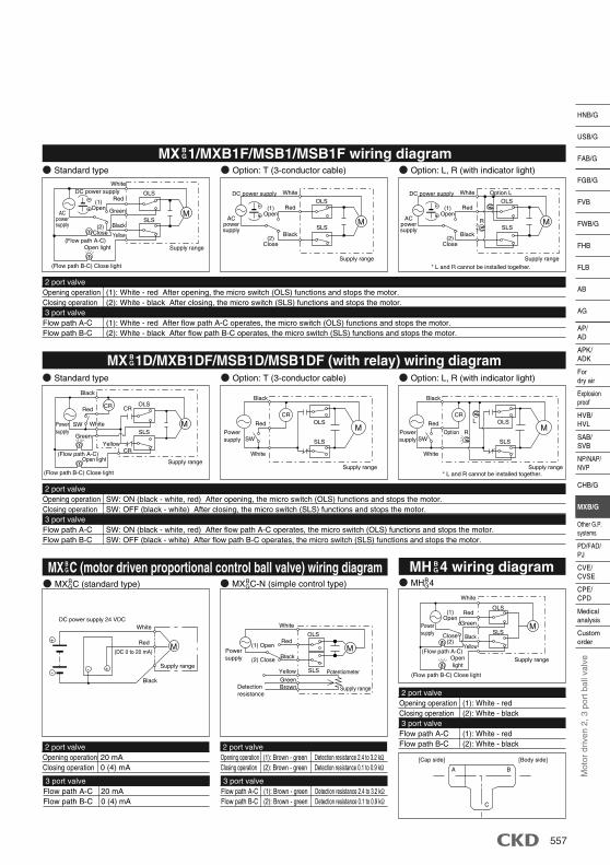
MX 1D/MXB1DF/MSB1D/MSB1DF (with relay) wiring diagramBG
2 port valveOpening operationClosing operation
(1): White - red After opening, the micro switch (OLS) functions and stops the motor. (2): White - black After closing, the micro switch (SLS) functions and stops the motor.
Flow path A-CFlow path B-C
(1): White - red After flow path A-C operates, the micro switch (OLS) functions and stops the motor. (2): White - black After flow path B-C operates, the micro switch (SLS) functions and stops the motor.
MX 1/MXB1F/MSB1/MSB1F wiring diagramBG
Standard type Option: T (3-conductor cable) Option: L, R (with indicator light)
3 port valve
2 port valveOpening operationClosing operation
SW: ON (black - white, red) After opening, the micro switch (OLS) functions and stops the motor. SW: OFF (black - white) After closing, the micro switch (SLS) functions and stops the motor.
Flow path A-CFlow path B-C
SW: ON (black - white, red) After flow path A-C operates, the micro switch (OLS) functions and stops the motor. SW: OFF (black - white) After flow path B-C operates, the micro switch (SLS) functions and stops the motor.
3 port valve
Standard type Option: T (3-conductor cable) Option: L, R (with indicator light)
MX C (motor driven proportional control ball valve) wiring diagramBG MH 4 wiring diagramB
G
2 port valveOpening operationClosing operation
20 mA0 (4) mA
3 port valveFlow path A-CFlow path B-C
20 mA0 (4) mA
2 port valveOpening operationClosing operation
(1): Brown - green(2): Brown - green
3 port valveFlow path A-CFlow path B-C
(1): Brown - green(2): Brown - green
Detection resistance 2.4 to 3.2 kΩDetection resistance 0.1 to 0.9 kΩ
Detection resistance 2.4 to 3.2 kΩDetection resistance 0.1 to 0.9 kΩ
White
Supply range
ACpowersupply
ACpowersupply
ACpowersupply
DC power supply
(1)Open
(2)Close
Red
Green
Black
Yellow(Flow path A-C)
Open light
OLS
MSLS
(Flow path B-C) Close light
White
Supply range
(1)Open
(2)Close
Red
Black
OLS
MSLS
A B
C
[Cap side] [Body side]
White
Supply range
(1)Open
Close(2)
Red
Green
Black
Yellow(Flow path A-C)
Openlight
OLS
MSLS
(Flow path B-C) Close light
Supply range
SW
CR CR
CR
Red
Green
Black
Yellow
(Flow path A-C)Open light
OLS
MSLS
(Flow path B-C) Close light
White
Supply range
SW
CR
Red
Black
OLSM
SLS
White
Supply range
Powersupply
Powersupply
Powersupply
SW
CR
Red
Black
OLSM
SLS
(DC 0 to 20 mA)
White
Supply range
DC power supply 24 VDC
Red
Black
M
-
+
+-
Supply range
White
Red
GreenBrown
Black
Yellow
Detectionresistance
(1) Open
(2) Close
Powersupply
OLS
SLS Potentiometer
M
DC power supply White
Supply range
(1)Open
(2)Close
Red
Black
OLS
MSLS
DC power supply
R
Option L
* L and R cannot be installed together.
R
L
* L and R cannot be installed together.
Option
Powersupply
White
MXBC/MXGC Series
598
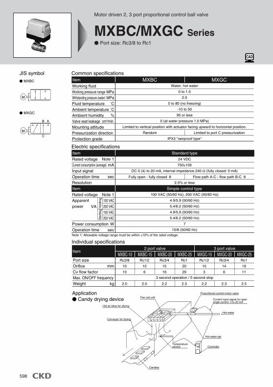
Individual specifications
ItemMXBC-20 MXBC-25 MXGC-15 MXGC-20
2 port valve 3 port valve
MXGC-25MXBC-15MXBC-10Port sizeOrificeCv flow factorMax. ON/OFF frequencyWeight
mm
kg
Rc3/8
10
10
2.0
Rc1/2
10
6
2.0
Rc3/4
15
16
2.2
Rc1
20
29
2.3
Rc1/2
10
3
2.2
Rc3/4
14
6
2.3
Rc1
19
11
2.5
3 second operation / 5 second stop
Fully open - fully closed 8 Flow path A-C - flow path B-C 8
Item100 VAC (50/60 Hz), 200 VAC (50/60 Hz)
4.9/5.9 (50/60 Hz)
5.4/6.2 (50/60 Hz)
4.9/5.9 (50/60 Hz)
5.4/6.2 (50/60 Hz)
7
10/8 (50/60 Hz)
Note 1100 VAC200 VAC100 VAC200 VAC
Wsec
Rated voltageApparentpower
Power consumptionOperation time
Simple control type
VA Hol
ding
Sta
rtin
g
Fan coil unit
Hot air blow for drying
Proportional control motor valve
Hot water pip
Hot water
ControllerTemperaturesensor
Candies
Current input signal for openangle control: 4 to 20 mA
Conveyer for drying
Application Candy drying device
Common specificationsItem
Water, hot water
0 to 1.0
2.0
0 to 80 (no freezing)
-10 to 50
95 or less
0 (at water pressure 1.0 MPa)
Limited to vertical position with actuator facing upward to horizontal position.
IPX3 "rainproof type"
MXBC MXGC
MPaMPa
˚C˚C%
cm3/min.
Working fluidWorking pressure rangeWithstanding pressure (water)Fluid temperatureAmbient temperatureAmbient humidityValve seat leakageMounting attitudePressurization directionProtection grade
Random Limited to port C pressurization
Electric specificationsItem
24 VDC
750±100
DC 0 (4) to 20 mA, internal impedance 240 Ω (fully closed: 0 mA)
2.5% or less
Note 1mA
sec
Rated voltageCurrent consumption (average)Input signalOperation timeResolution
Standard type
Note 1: Allowable voltage range must be within ±10% of the rated voltage.
JIS symbol
MXBC
MXGC
M
M
AB
C
Motor driven 2, 3 port proportional control ball valve
MXBC/MXGC Series Port size: Rc3/8 to Rc1
MXBC/MXGC Series
599
AP/AD
HNB/G
USB/G
FAB/G
FGB/G
FVB
FWB/G
FHB
FLB
AB
AG
CHB/G
MXB/G
SAB/SVB
HVB/HVL
Fordry air
NP/NAP/NVP
PD/FAD/PJ
CVE/CVSE
CPE/CPD
Customorder
Medicalanalysis
Other G.P.systems
APK/ADK
Explosionproof
Pro
port
iona
l con
trol
Mot
or d
riven
2, 3
por
t bal
l val
ve
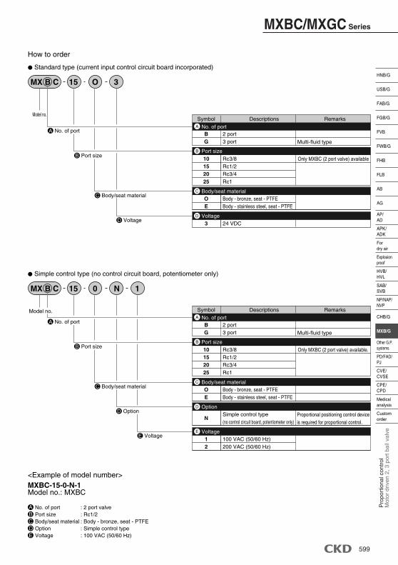
MX B C 15 O 3
Model no.
Standard type (current input control circuit board incorporated)
MX B C 15 10 N
Model no.
Simple control type (no control circuit board, potentiometer only)
How to order
Descriptions RemarksSymbol
BG
2 port3 port Multi-fluid type
A
10152025
Rc3/8Rc1/2Rc3/4Rc1
Only MXBC (2 port valve) available
B
OE
Body - bronze, seat - PTFEBody - stainless steel, seat - PTFE
C
3 24 VDC
D Voltage
Body/seat material
Port size
No. of port
Descriptions RemarksSymbol
BG
2 port3 port Multi-fluid type
A
10152025
Rc3/8Rc1/2Rc3/4Rc1
Only MXBC (2 port valve) available.
B
OE
Body - bronze, seat - PTFEBody - stainless steel, seat - PTFE
C
12
100 VAC (50/60 Hz)200 VAC (50/60 Hz)
E
NSimple control type(no control circuit board, potentiometer only)
D
Proportional positioning control deviceis required for proportional control.
Option
Voltage
Body/seat material
Port size
No. of port
D Option
E Voltage
A No. of port
B Port size
C Body/seat material
D Voltage
A No. of port
B Port size
C Body/seat material
<Example of model number>MXBC-15-0-N-1Model no.: MXBC
ABCDE
No. of port : 2 port valvePort size : Rc1/2Body/seat material : Body - bronze, seat - PTFEOption : Simple control typeVoltage : 100 VAC (50/60 Hz)
MXBC/MXGC Series
600
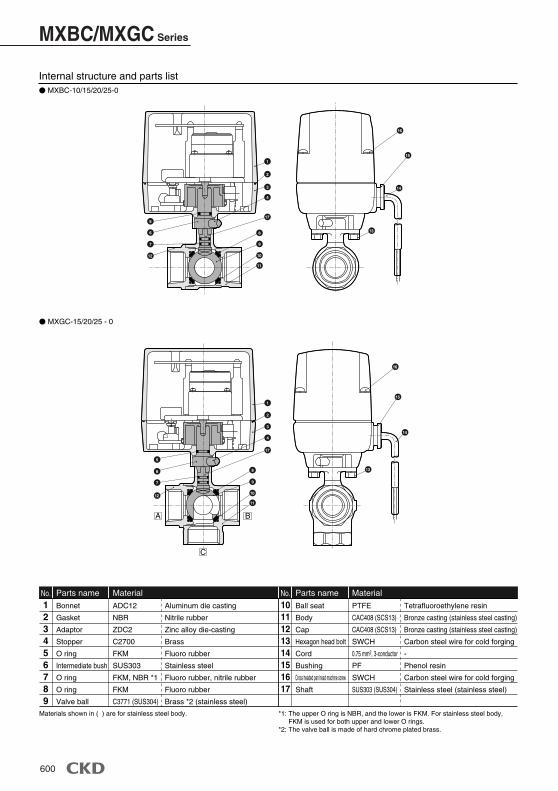
Internal structure and parts list MXBC-10/15/20/25-0
Bonnet
Gasket
Adaptor
Stopper
O ring
Intermediate bush
O ring
O ring
Valve ball
123456789
Parts name
ADC12
NBR
ZDC2
C2700
FKM
SUS303
FKM, NBR *1
FKM
C3771 (SUS304)
MaterialNo.Ball seat
Body
Cap
Hexagon head bolt
Cord
Bushing
Cross headed pan head machine screw
Shaft
1011121314151617
Parts name
PTFE
CAC408 (SCS13)
CAC408 (SCS13)
SWCH
0.75 mm2, 3-conductor
PF
SWCH
SUS303 (SUS304)
MaterialNo.Aluminum die casting
Nitrile rubber
Zinc alloy die-casting
Brass
Fluoro rubber
Stainless steel
Fluoro rubber, nitrile rubber
Fluoro rubber
Brass *2 (stainless steel)
Tetrafluoroethylene resin
Bronze casting (stainless steel casting)
Bronze casting (stainless steel casting)
Carbon steel wire for cold forging
-
Phenol resin
Carbon steel wire for cold forging
Stainless steel (stainless steel)
MXGC-15/20/25 - 0
*1: The upper O ring is NBR, and the lower is FKM. For stainless steel body,FKM is used for both upper and lower O rings.
*2: The valve ball is made of hard chrome plated brass.
Materials shown in ( ) are for stainless steel body.
A B
C
1
2
3
4
5
6
7
8
9
10
11
12
13
14
15
16
17
1
2
3
4
5
6
7
8
9
10
11
12
13
14
15
16
17
MXBC/MXGC Series
601
AP/AD
HNB/G
USB/G
FAB/G
FGB/G
FVB
FWB/G
FHB
FLB
AB
AG
CHB/G
MXB/G
SAB/SVB
HVB/HVL
Fordry air
NP/NAP/NVP
PD/FAD/PJ
CVE/CVSE
CPE/CPD
Customorder
Medicalanalysis
Other G.P.systems
APK/ADK
Explosionproof
Pro
port
iona
l con
trol
Mot
or d
riven
2, 3
por
t bal
l val
ve
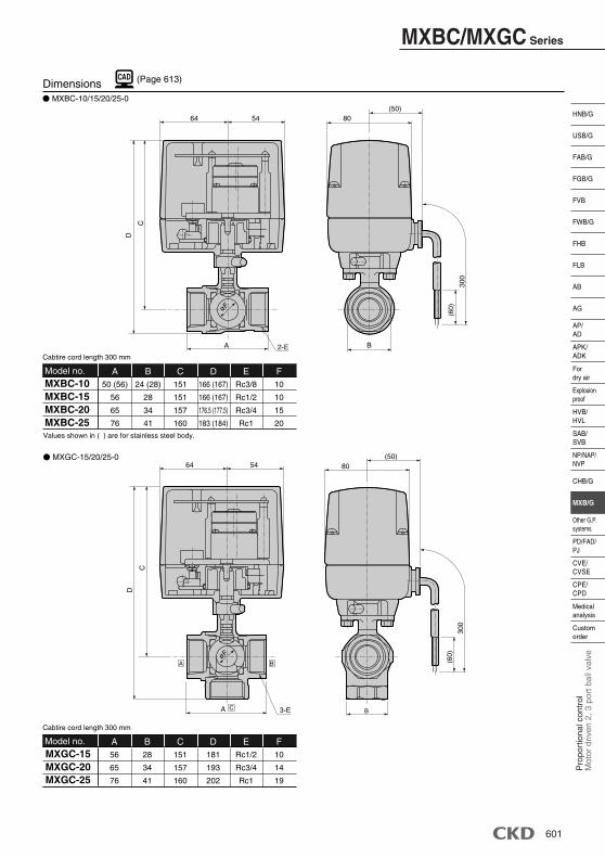
Dimensions MXBC-10/15/20/25-0
(Page 613)
MXBC-10MXBC-15MXBC-20MXBC-25
A B C DRc3/8
Rc1/2
Rc3/4
Rc1
10
10
15
20
166 (167)
166 (167)
176.5 (177.5)
183 (184)
151
151
157
160
24 (28)
28
34
41
50 (56)
56
65
76
E FModel no.
MXGC-15MXGC-20MXGC-25
A B C DRc1/2
Rc3/4
Rc1
10
14
19
181
193
202
151
157
160
28
34
41
56
65
76
E FModel no.
MXGC-15/20/25-0
Values shown in ( ) are for stainless steel body.
Cabtire cord length 300 mm
Cabtire cord length 300 mm
64 54
2-EA
C
D
(50)80
B
(60)
300
D
C
64 54
A 3-E
A B
C B
(60)
300
80(50)
øF
øF
612
Model no. MICRO CADAMFolder name Filename (GROUP: CAD, USER: STDLIB)Filename
DXF
Model no. MICRO CADAMFolder name Filename (GROUP: CAD, USER: STDLIB)Filename
DXF
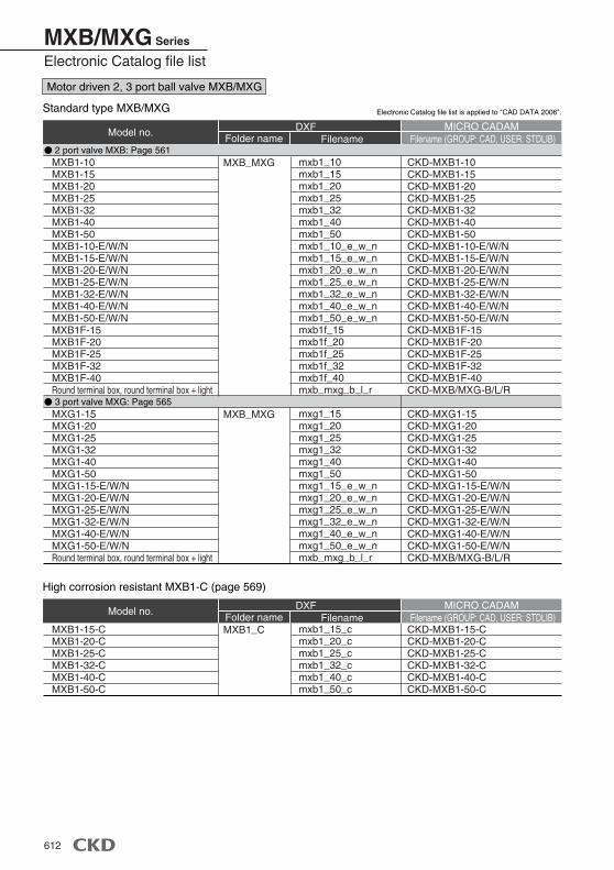
Standard type MXB/MXG
MXB1-10MXB1-15MXB1-20MXB1-25MXB1-32MXB1-40MXB1-50MXB1-10-E/W/NMXB1-15-E/W/NMXB1-20-E/W/NMXB1-25-E/W/NMXB1-32-E/W/NMXB1-40-E/W/NMXB1-50-E/W/NMXB1F-15MXB1F-20MXB1F-25MXB1F-32MXB1F-40Round terminal box, round terminal box + light
MXG1-15MXG1-20MXG1-25MXG1-32MXG1-40MXG1-50MXG1-15-E/W/NMXG1-20-E/W/NMXG1-25-E/W/NMXG1-32-E/W/NMXG1-40-E/W/NMXG1-50-E/W/NRound terminal box, round terminal box + light
2 port valve MXB: Page 561
3 port valve MXG: Page 565
mxb1_10mxb1_15mxb1_20mxb1_25mxb1_32mxb1_40mxb1_50mxb1_10_e_w_nmxb1_15_e_w_nmxb1_20_e_w_nmxb1_25_e_w_nmxb1_32_e_w_nmxb1_40_e_w_nmxb1_50_e_w_nmxb1f_15mxb1f_20mxb1f_25mxb1f_32mxb1f_40mxb_mxg_b_l_r
mxg1_15mxg1_20mxg1_25mxg1_32mxg1_40mxg1_50mxg1_15_e_w_nmxg1_20_e_w_nmxg1_25_e_w_nmxg1_32_e_w_nmxg1_40_e_w_nmxg1_50_e_w_nmxb_mxg_b_l_r
MXB_MXG
MXB_MXG
CKD-MXB1-10CKD-MXB1-15CKD-MXB1-20CKD-MXB1-25CKD-MXB1-32CKD-MXB1-40CKD-MXB1-50CKD-MXB1-10-E/W/NCKD-MXB1-15-E/W/NCKD-MXB1-20-E/W/NCKD-MXB1-25-E/W/NCKD-MXB1-32-E/W/NCKD-MXB1-40-E/W/NCKD-MXB1-50-E/W/NCKD-MXB1F-15CKD-MXB1F-20CKD-MXB1F-25CKD-MXB1F-32CKD-MXB1F-40CKD-MXB/MXG-B/L/R
CKD-MXG1-15CKD-MXG1-20CKD-MXG1-25CKD-MXG1-32CKD-MXG1-40CKD-MXG1-50CKD-MXG1-15-E/W/NCKD-MXG1-20-E/W/NCKD-MXG1-25-E/W/NCKD-MXG1-32-E/W/NCKD-MXG1-40-E/W/NCKD-MXG1-50-E/W/NCKD-MXB/MXG-B/L/R
High corrosion resistant MXB1-C (page 569)
MXB1-15-CMXB1-20-CMXB1-25-CMXB1-32-CMXB1-40-CMXB1-50-C
mxb1_15_cmxb1_20_cmxb1_25_cmxb1_32_cmxb1_40_cmxb1_50_c
MXB1_C CKD-MXB1-15-CCKD-MXB1-20-CCKD-MXB1-25-CCKD-MXB1-32-CCKD-MXB1-40-CCKD-MXB1-50-C
Electronic Catalog file list is applied to "CAD DATA 2006".
Motor driven 2, 3 port ball valve MXB/MXG
MXB/MXG Series
Electronic Catalog file list
613
AP/AD
HNB/G
USB/G
FAB/G
FGB/G
FVB
FWB/G
FHB
FLB
AB
AG
CHB/G
MXB/G
SAB/SVB
HVB/HVL
Fordry air
NP/NAP/NVP
PD/FAD/PJ
CVE/CVSE
CPE/CPD
Customorder
Medicalanalysis
Other G.P.systems
APK/ADK
Explosionproof
Dire
ct a
ctin
g 2,
3 p
ort s
olen
oid
valv
e
Model no. MICRO CADAMFilename (GROUP: CAD, USER: STDLIB)Filename
DXF
Model no. MICRO CADAMFilename (GROUP: CAD, USER: STDLIB)Filename
DXF
Model no. MICRO CADAMFilename (GROUP: CAD, USER: STDLIB)Filename
DXF
Model no. MICRO CADAMFilename (GROUP: CAD, USER: STDLIB)Filename
DXF
Folder name
Folder name
Folder name
Folder name
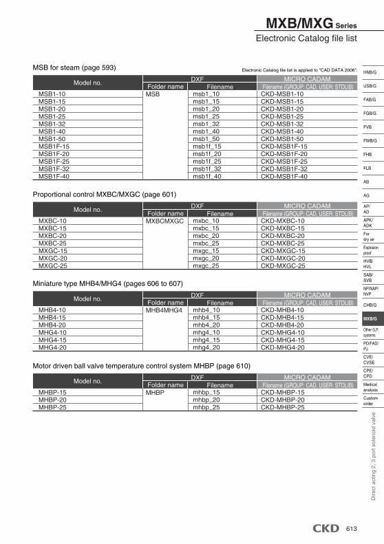
MSB for steam (page 593)
MSB1-10MSB1-15MSB1-20MSB1-25MSB1-32MSB1-40MSB1-50MSB1F-15MSB1F-20MSB1F-25MSB1F-32MSB1F-40
msb1_10msb1_15msb1_20msb1_25msb1_32msb1_40msb1_50msb1f_15msb1f_20msb1f_25msb1f_32msb1f_40
MSB CKD-MSB1-10CKD-MSB1-15CKD-MSB1-20CKD-MSB1-25CKD-MSB1-32CKD-MSB1-40CKD-MSB1-50CKD-MSB1F-15CKD-MSB1F-20CKD-MSB1F-25CKD-MSB1F-32CKD-MSB1F-40
Proportional control MXBC/MXGC (page 601)
MXBC-10MXBC-15MXBC-20MXBC-25MXGC-15MXGC-20MXGC-25
mxbc_10mxbc_15mxbc_20mxbc_25mxgc_15mxgc_20mxgc_25
MXBCMXGC CKD-MXBC-10CKD-MXBC-15CKD-MXBC-20CKD-MXBC-25CKD-MXGC-15CKD-MXGC-20CKD-MXGC-25
Miniature type MHB4/MHG4 (pages 606 to 607)
MHB4-10MHB4-15MHB4-20MHG4-10MHG4-15MHG4-20
mhb4_10mhb4_15mhb4_20mhg4_10mhg4_15mhg4_20
MHB4MHG4 CKD-MHB4-10CKD-MHB4-15CKD-MHB4-20CKD-MHG4-10CKD-MHG4-15CKD-MHG4-20
Motor driven ball valve temperature control system MHBP (page 610)
MHBP-15MHBP-20MHBP-25
mhbp_15mhbp_20mhbp_25
MHBP CKD-MHBP-15CKD-MHBP-20CKD-MHBP-25
Electronic Catalog file list is applied to "CAD DATA 2006".
MXB/MXG Series
Electronic Catalog file list