Embed Size (px)
Citation preview

MX7 User’s Guide (Microsoft® Windows® CE 5.0 Equipped)
Copyright © 2006 by LXE Inc. All Rights Reserved E-EQ-MX7OGWW-C
Language: English Notices
LXE Inc. reserves the right to make improvements or changes in the products described in this guide at any time without notice. While reasonable efforts have been made in the preparation of this document to assure its accuracy, LXE assumes no liability resulting from any errors or omissions in this document, or from the use of the information contained herein. Further, LXE Incorporated, reserves the right to revise this publication and to make changes to it from time to time without any obligation to notify any person or organization of such revision or changes.
Copyright:
This document is copyrighted. All rights are reserved. This document may not, in whole or in part, be copied, photocopied, reproduced, translated or reduced to any electronic medium or machine-readable form without prior consent, in writing, from LXE Inc.
Copyright © 2006 by LXE Inc. An EMS Technologies Company. 125 Technology Parkway, Norcross, GA 30092 U.S.A. (770) 447-4224
Trademarks: LXE® is a registered trademark of LXE Inc. Odyssey Client © Copyright 2002-2006 Funk Software, Inc. All rights reserved. Odyssey® and Funk® are registered trademarks of Funk Software, Inc. Summit Data Communications, Inc. Summit Data Communications, the Summit logo, and “The Pinnacle of Performance” are trademarks of Summit Data Communications, Inc. Microsoft®, Windows® and the Windows logo are registered trademarks of Microsoft Corporation in the United States and/or other countries. Java® and Java-based trademarks and logos are trademarks or registered trademarks of Sun Microsystems, Inc. in the U.S. or other countries, and are used under license. RAM® and RAM Mount™ are both trademarks of National Products Inc., 1205 S. Orr Street, Seattle, WA 98108. All other brand or product names are trademarks or registered trademarks of their respective companies or organizations. When this document is in PDF format: “Acrobat ® Reader Copyright © 1987-2006 Adobe Systems Incorporated. All rights reserved. Adobe, the Adobe logo, Acrobat, and the Acrobat logo are trademarks of Adobe Systems Incorporated.” Applies.
Republic of Singapore – LXE Dealer License Number DA103458 complies with IDA Standards.
Initial Release December 2005, Revision B Release August 2006.
The user is strongly encouraged to read Appendix B, “Regulatory Notices and Safety Information”. Important safety cautions, warnings and regulatory information is contained in
Appendix B.
Important: This symbol is placed on the product to remind users to dispose of Waste Electrical and Electronic Equipment (WEEE) appropriately, per Directive 2002-96-EC. In most areas, this product can be recycled, reclaimed and re-used when properly discarded. Do not discard labeled units with trash. For information about proper disposal, contact LXE through your local sales representative, or visit www lxe com.

Revision Notice
Rev. Section Explanation
B Notices and Appendix B – Regulatory Notices and Safety Information
(May 2006) Added label and text : “Republic of Singapore – LXE Dealer License Number DA103458 complies with IDA Standards.”
C Introduction (August 2006) Added Laser Label for Summit Client . Laser Label for Odyssey Client does not change.
C
Quick Start
Added section titled “MX7 Features”. Added figure titled “MX7 Desktop.”
Added Multi AppLock activation key instruction “Entering the Multi AppLock Activation Key”.
“Installing Trigger Handle”: Added: “Equipment Needed: Torque wrench capable of torquing to 3±1 in/lb (.34± .11 N/m)”. Removed “and washers” from step 5 and included torque instruction in step 6.
Expanded instruction when using audio cable and headsets “Connecting the Audio Cable and a Headset”.
Added note about SE 824 scanner and it’s SE 955 replacement effective July 2006.
Added note to LXE Login Utility: “Should only be used with Odyssey Clients”.
Accessories: Added ROHS indicators. Added Voice accessories. Removed MX7A309PSACWW. Added 9000A302PSACWW – AC/DC power supply, int’l, no power cord.
C Appendix B – Regulatory Notices and Safety Information
Added Summit Radio to Approvals section.
Added Laser Labels for Summit Client Mobile Device. Laser labels for Odyssey Client do not change.
C Entire Manual Removed all reference to Bluetooth except to state that Bluetooth is not supported by LXE.


E-EQ-MX7OGWW-C MX7 User’s Guide
Table of Contents
INTRODUCTION 1
Overview.................................................................................................................................... 1 MX7 Features .......................................................................................................................................... 2 Important Battery Information................................................................................................................. 3 Document Conventions ........................................................................................................................... 4 Environmental Specifications .................................................................................................................. 4
Laser Warnings and Labels.....................................................................................................5 Components.............................................................................................................................. 6
Front Views ............................................................................................................................................. 6 Back View ............................................................................................................................................... 7 Scanner / Imager Aperture....................................................................................................................... 8 AC Adapter.............................................................................................................................................. 8 Cables ...................................................................................................................................................... 9 Handle and Handstrap............................................................................................................................ 10
QUICK START 11
In Brief . . . ............................................................................................................................... 11 Troubleshooting..................................................................................................................................... 12
Installing Trigger Handle (Optional)......................................................................................13 Inserting Fully Charged Battery ............................................................................................14 Tapping the Power Key..........................................................................................................15 Checking Battery Status ........................................................................................................15 Entering the Login Name .......................................................................................................15 Tapping the Touchscreen with a Stylus ...............................................................................16
Keypad Shortcuts................................................................................................................................... 16 Calibrating the Touchscreen .................................................................................................17 Entering the Multi AppLock Activation Key.........................................................................17
Hotkey ................................................................................................................................................... 17 Touch ..................................................................................................................................................... 17
Optional Accessory Installation............................................................................................18 Attaching Handstrap .............................................................................................................................. 18 Connecting an External Power Supply (Optional)................................................................................. 19
Putting it all together …...................................................................................................................... 19 Assembling the AC Power Adapter .................................................................................................... 19 Connecting the Multipurpose USB / Power Cable.............................................................................. 20 Connecting the Multipurpose RS-232 / Power Cable ......................................................................... 20 Connecting to a Printer Interface Cable .............................................................................................. 21 Connecting the Audio Cable and a Headset........................................................................................ 21
Adjust Microphone and Secure the Cable ........................................................................................ 22 Entering Data.................................................................................................................................... 22
Using the 55 Key ANSI / CE Keypad .....................................................................................23 Using the 32-Key Numeric-Alpha Keypad............................................................................24 Entering Data .......................................................................................................................... 25

ii Table of Contents
MX7 User’s Guide E-EQ-MX7OGWW-C
Keypad Entry ......................................................................................................................................... 25 Stylus Data Entry................................................................................................................................... 25 Scanner Entry......................................................................................................................................... 26 Tethered Scanners.................................................................................................................................. 26 Voice Data ............................................................................................................................................. 26 Input Panel – Virtual Keyboard ............................................................................................................. 27
Getting Help ............................................................................................................................ 28 Manuals ................................................................................................................................................. 28 Accessories ............................................................................................................................................ 28
THE MX7 HAND HELD COMPUTER 31
Reboot Sequence ................................................................................................................... 31 Warm Reset ........................................................................................................................................... 31 Cold Reset.............................................................................................................................................. 31
Saving Changes to the Registry ...........................................................................................31 Touchscreen Display ............................................................................................................. 32
Applying the Protective Film to the Display ......................................................................................... 32 Touchscreen Calibration ........................................................................................................................ 33 Cleaning the Glass Display/Scanner Aperture....................................................................................... 33
Adjusting the Display Backlight............................................................................................34 Set the Display Backlight Brightness .................................................................................................... 34 Set the Display Backlight Timer............................................................................................................ 34
Setting the Power Schemes Timers......................................................................................35 Battery Power Scheme........................................................................................................................... 35 AC Power Scheme................................................................................................................................. 35
Setting The Audio Speaker Volume......................................................................................36 Using the Keypad .................................................................................................................................. 36 Using the Touchscreen .......................................................................................................................... 37
The Keypads ........................................................................................................................... 38 LED Indicators....................................................................................................................................... 39
System Status ...................................................................................................................................... 39 Scan Status .......................................................................................................................................... 39 Alpha Mode (32-key Alph Key) ......................................................................................................... 39
Standard Keys........................................................................................................................................ 40 Function Keys........................................................................................................................................ 40
Sticky Keys ......................................................................................................................................... 40 Ctl / Ctrl (Control key) ..................................................................................................................... 40 Alt (Alternate key)............................................................................................................................ 40 Shft (Shift key) ................................................................................................................................. 40 Orange and Blue Keys...................................................................................................................... 41
Field Exit............................................................................................................................................. 41 Mode Key Functions ........................................................................................................................... 42
CapsLock Mode................................................................................................................................ 42 55-Key Keypad .............................................................................................................................. 42 32-Key Keypad .............................................................................................................................. 42
Mappable Diamond Keys ...................................................................................................................... 43 55 Key Keypad.................................................................................................................................... 43 32 Key Keypad.................................................................................................................................... 44
Batteries .................................................................................................................................. 45 Main Battery .......................................................................................................................................... 45
Table of Contents iii
E-EQ-MX7OGWW-C MX7 User’s Guide
Backup Battery ...................................................................................................................................... 45 Battery Hotswapping ............................................................................................................................. 46
Battery Chargers .................................................................................................................... 47 Charge Main Battery in MX7 Multi-Charger ........................................................................................ 47
Passive Vehicle Mount Cradle...............................................................................................49 Cradle Assembly Components .............................................................................................................. 50
U-Bracket ............................................................................................................................................ 50 U-Bracket Footprint.......................................................................................................................... 50
RAM Ball and Cylinder ...................................................................................................................... 51 RAM Assembly Footprint ................................................................................................................ 52
How to Install the Cradle U-Bracket ..................................................................................................... 53 How To Install the RAM Bracket.......................................................................................................... 55
APPENDIX A KEY MAPS 59
Introduction............................................................................................................................. 59 55-Key Alphanumeric Keymaps............................................................................................59
ANSI / CE Keypad ................................................................................................................................ 59 5250 Key Map for the 55-Key Keypad ................................................................................................. 64
32-Key Numeric-Alpha Keypad .............................................................................................65
APPENDIX B REGULATORY NOTICES AND SAFETY INFORMATION 71
MX7 Approvals/Standards .....................................................................................................72
INDEX 81

iv Table of Contents
MX7 User’s Guide E-EQ-MX7OGWW-C
Illustrations Figure 1 CDRH / IEC 825 Caution Label Location – MX7, Back ...................................................................5 Figure 2 Caution Label – Class 2 Laser Scanner ..............................................................................................5 Figure 3 Front Components ..............................................................................................................................6 Figure 4 Back Components...............................................................................................................................7 Figure 5 Scanner Aperture ................................................................................................................................8 Figure 6 AC Adapter.........................................................................................................................................8 Figure 7 Handle and Handstrap.......................................................................................................................10 Figure 8 MX7 Desktop ...................................................................................................................................11 Figure 9 Handle Attach Points ........................................................................................................................13 Figure 10 Main Battery Pack ..........................................................................................................................14 Figure 11 Power Key Location .......................................................................................................................15 Figure 12 Touchscreen Recalibration .............................................................................................................17 Figure 13 Attaching the Handstrap .................................................................................................................18 Figure 14 USB – MX7 – Power Assembly .....................................................................................................19 Figure 15 AC/DC 12V External Power Supply ..............................................................................................19 Figure 16 Connect the USB / Power Cable to the MX7 Port ..........................................................................20 Figure 17 Connect the RS-232 / Power Cable to the MX7 Port......................................................................20 Figure 18 Connect to a Printer Interface Cable...............................................................................................21 Figure 19 Audio Cable and Headset ...............................................................................................................21 Figure 20 Scan Beam ......................................................................................................................................26 Figure 21 Scan Status LED.............................................................................................................................26 Figure 22 Input Panel / Virtual Keyboard.......................................................................................................27 Figure 23 Touchscreen Display ......................................................................................................................32 Figure 24 Touchscreen Recalibration .............................................................................................................33 Figure 25 Setting the Display Backlight Timer...............................................................................................34 Figure 26 Volume & Sounds Properties .........................................................................................................37 Figure 27 The 32-key and 55-key Keypads ....................................................................................................38 Figure 28 Mappable Diamond Keys ...............................................................................................................43 Figure 29 Lithium Ion Battery Pack.................................................................................................................45 Figure 30 MX7 Multi-Charger / Analyzer ......................................................................................................47 Figure 31 Insert Battery Pack in Charging Pocket ..........................................................................................48 Figure 32 Passive Vehicle Mount Cradle and U-Bracket ...............................................................................50 Figure 33 U-Bracket Mounting Footprint .......................................................................................................50 Figure 34 Passive Vehicle Mount Cradle / RAM Ball Assembly ...................................................................51 Figure 35 RAM Bracket Components.............................................................................................................51 Figure 36 RAM Assembly Footprint ..............................................................................................................52 Figure 37 Installing the Cradle U-Bracket ......................................................................................................53 Figure 38 Installing the RAM Assembly ........................................................................................................55

E-EQ-MX7OGWW-C MX7 User’s Guide
Introduction
Overview
The LXE® MX7 is a rugged, portable, hand-held Microsoft® Windows® CE 5.0 equipped mobile computer capable of wireless data communications. The mobile device can transmit information using an 802.11 radio and it can store information for later transmission through an RS-232 or USB port.
The mobile device is vertically oriented and features backlighting for the display. The touch-screen display supports graphic features and Windows icons that the Windows CE 5.0 operating system supports. Keypads are available in 55-key alphanumeric and 32-key numeric-alpha versions. Also available is a 5250 55-key keypad overlay.
This device is a Windows CE 5.0 compatible computer that can be scaled from a limited function batch computer to an integrated RF scanning computer. A trigger handle is available as an accessory.
The attached stylus is used to assist in entering data and configuring the mobile device. Protective film for the touchscreen is available as an accessory.
The MX7 is powered by a 2200 mAh Lithium-Ion main battery pack and an internal NiCd backup battery.
Important
If the mobile device has AppLock installed, please refer to the “MX7 Reference Guide”, “Chapter 4 – AppLock” for setup and processing.
Wireless configuration and security parameters are described in detail in the “MX7 Reference Guide”, “Chapter 5 – Wireless Network Configuration”.
Related Manuals
Instructions for setting up the integrated SE824, SE955 or SE1524 scanner barcode reading parameters, are contained in Chapter 2 of the “Integrated Scanner Programming Guide” on the LXE Manuals CD or the LXE ServicePass website. Note: The SE955 scanner replaced the SE824 scanner on all MX7’s manufactured after July 2006.
For instructions in setting up the Intermec EV15 linear imager, please refer to Chapter 3 in the “Integrated Scanner Programming Guide”.

2 Overview
MX7 User’s Guide E-EQ-MX7OGWW-C
MX7 Features New features affect user interaction and internal operation of the MX7.
The appropriate radio utility for your device configuration has been pre-installed by LXE. The desktop will display an Odyssey Client Utility icon or it will display a Summit Client Utility icon for 802.11 configuration and security.
Odyssey Summit Optional?
Summit Client Utility - x No
Odyssey Client Utility x - No
400MHz x x No
128MB RAM x x No
128MB Flash x x No
SE955 Scanner - x Yes
EV-15 Scanner x x Yes
SE824 Scanner x - Yes
CE 5.0 x x No
Voice - x Yes
RFTerm x x Yes
JAVA x x Yes
AppLock x x Yes
Multi AppLock x x Yes
Note: The LXE Login Utility should be used by Odyssey Clients only.
Note: There is no IR port on the MX7. Tethered scanners are not supported on the MX7. Bluetooth is not supported by LXE.

Overview 3
E-EQ-MX7OGWW-C MX7 User’s Guide
Important Battery Information
Note: This mobile device’s backup battery maintains it’s charge by drawing power from the main battery pack. Always store unused devices with a fully charged main battery pack installed. LXE recommends an in-use mobile device be frequently connected to an external power source to maintain optimum power levels in the main battery pack and the backup battery. When the backup battery and main battery pack are dead, the mobile device reverts to the last saved setup defaults when a fully charged main battery pack is installed and the device is powered On again.
Tap | Settings | Control Panel | Battery tab.
• Until the main battery and backup battery are completely depleted, the MX7 is always drawing power from the batteries (On).
• New batteries must be fully charged prior to use.
• Whenever possible, use the AC power adapter with the MX7 to conserve the main battery and recharge the backup battery.
• When a new battery is installed in the MX7 for the first time (or when the backup battery is completely depleted), the Time and Date reverts to it’s default values.
• Backup battery replacement is performed by LXE.
Tap | Settings | Control Panel | Date/Time tab.
CAUTION
RISK OF EXPLOSION IF BATTERY IS REPLACED BY AN INCORRECT TYPE.
DISPOSE OF USED BATTERIES ACCORDING TO THE INSTRUCTIONS.
ATTENTION
II y a danger d’explosion s’il y a remplacement incorrect de la batterie.
Remplacer uniquement avec une batterie du même type ou d’un type equivalent recommandé par le constructeur. Mettre au rebut les batteries usagées conformément aux instructions du fabricant.

4 Overview
MX7 User’s Guide E-EQ-MX7OGWW-C
Document Conventions ALL CAPS All caps are used to represent disk directories, file names, and application names.
Menu | Choice Rather than use the phrase “choose the Save command from the File menu”, this guide uses the convention “choose File | Save”.
“Quotes” Indicates the title of a book, chapter or a section within a chapter (for example, “Document Conventions”).
< > Indicates a key on the keypad (for example, <Enter> ).
Indicates a reference to other documentation.
ATTENTION Keyword that indicates vital or pivotal information to follow.
Attention symbol that indicates vital or pivotal information to follow. Also, when marked on product, means to refer to the user’s guide.
International fuse replacement symbol. When marked on the product, the label includes fuse ratings in volts (v) and amperes (a) for the product.
Note: Keyword that indicates immediately relevant information.
CAUTION
Keyword that indicates a potentially hazardous situation which, if not avoided, may result in minor or moderate injury.
WARNING
Keyword that indicates a potentially hazardous situation which, if not avoided, could result in death or serious injury.
DANGER
Keyword that indicates a imminent hazardous situation which, if not avoided, will result in death or serious injury.
Environmental Specifications Operating Temperature 14°F to 122°F (-10°C to 50°C) [non-condensing] Storage Temperature -4°F to 158°F (-20°C to 70°C) [non-condensing] Water and Dust IEC 60529 compliant to IP54 Operating Humidity 5% to 90% non-condensing at 104°F (40°C) Vibration Based on MIL Std 810D ESD 8 kV air, 4kV contact

Laser Warnings and Labels 5
E-EQ-MX7OGWW-C MX7 User’s Guide
Laser Warnings and Labels
• Do not look into the laser’s lens.
• Do not stare directly into the laser beam.
• Do not remove the laser caution labels from the MX7.
• Do not connect the laser barcode window to any other device. The laser barcode window is certified for use with the MX7 only.
Caution:
Laser radiation when open. Please read the caution labels.
Use of controls, adjustments or performance of procedures other than those specified herein may result in hazardous radiation exposure.
Summit Client Laser Label
Odyssey Client Laser Label
Figure 1 CDRH / IEC 825 Caution Label Location – MX7, Back
Figure 2 Caution Label – Class 2 Laser Scanner

6 Components
MX7 User’s Guide E-EQ-MX7OGWW-C
Components
Front Views
BkSp
+
F11
MX7
PgDn PgUp
F6
F13 F14
Caps
Esc
| ~ : #
; * ,> /Ins<
. (?
=) \! $ %
^& @ }{ [
]
| ~ : #
; * ,> /Ins<
. (?
=) \! $ %
^& @ }{ [
]
F11
MX7
PgDn PgUp
F6
F13 F14
*
BkSpEsc
Caps
+
| :
#
;
,
/
(
?
= )
\
!
$
^
[ ]
Front – 55 Key Front – 32 Key
Figure 3 Front Components
1 Scanner Aperture 2 Speaker 3 System Status LED 4 Scan Button 5 Orange Key (Sticky Key) 6 Blue Key (Sticky Key) 7 Scan Status LED 8 Cable Port 9 On / Off Button
10 “Alpha” Lock LED
Diamond Number Keys

Components 7
E-EQ-MX7OGWW-C MX7 User’s Guide
Back View
Figure 4 Back Components
1 Scanner Aperture 2 Stylus and stylus holder
3 Trigger Handle Attach Points and Handstrap Retainer Bracket Attach Points
4 Main Battery 5 Battery Fastener 6 Cable Ports

8 Components
MX7 User’s Guide E-EQ-MX7OGWW-C
Scanner / Imager Aperture
Figure 5 Scanner Aperture
Note: The Imager has clear plastic protecting the imager engine. The Scanner has red plastic protecting the scanner engine. The No-Scanner option has an opaque window protecting the MX7 internal components.
AC Adapter
AC Adapter AC Power Cable
Figure 6 AC Adapter

Components 9
E-EQ-MX7OGWW-C MX7 User’s Guide
Cables
Cable: Multipurpose RS-232 and Power
MX7A055MULTICBLDA9F
Cable: Multipurpose USB and Power
MX7A052MULTICBLUSB
Adapter/Cable : Audio
MX7A060ADPTCBLVOICE
Adapter: RS-232 PC port to D9 male
MX7A058ADPTCBLPER

10 Components
MX7 User’s Guide E-EQ-MX7OGWW-C
Handle and Handstrap
Handle Handstrap
Figure 7 Handle and Handstrap
1 Scan Aperture 1 Handstrap Retainer Bracket
2 Trigger 2 Handstrap
3 Handle 3 Handstrap Clip
4 Tether Attach Point
Note: Either the trigger handle is attached to the MX7 or the handstrap is attached, not both. LXE recommends that, in the absence of a trigger handle, the handstrap be used at all times.
LXE pre-installs the handstrap when the MX7 is purchased without a trigger handle.

E-EQ-MX7OGWW-C MX7 User’s Guide
Quick Start
In Brief . . .
Note: When your mobile device is pre-configured, the radio, keypad and scan aperture configurations are assembled by LXE to your specifications. The desktop will display an Odyssey Client Utility icon or it will display a Summit Client Utility icon.
This section’s instructions are based on the assumption that your new device is pre-configured and requires only accessory installation (e.g. stylus) and a power source. LXE recommends that installation or removal of accessories be performed on a clean, well-lit surface. When necessary, protect the work surface, the mobile device, and components from electrostatic discharge.
This guide takes you through an introduction to and operation of the MX7.
1. Insert a fully charged main battery pack. (Always put a fully charged battery in the mobile device at the beginning of the shift or workday.)
2. Connect an external power source to the unit (if required).
3. If the screen does not automatically display, tap the Power key.
4. Calibrate the touchscreen.
5. A white screen will appear during the boot process until all CAB files and applications are loaded and installed. Radio setup screens may appear and disappear while files are loading. After all files are loaded and the Desktop is displayed, adjust audio volume and other parameters if desired.
If needed, change the Time and Date from it’s default value by tapping the | Settings | Control Panel | Date/Time icon.
MX7 with Odyssey Client MX7 with Summit Client
Figure 8 MX7 Desktop

12 In Brief . . .
MX7 User’s Guide E-EQ-MX7OGWW-C
Troubleshooting
Can’t calibrate the touch screen, change the date/time or adjust the volume.
AppLock is installed and running on the mobile device. AppLock restricts User access to running programs. Changes or modifications require Administrator access.
Refer to the “MX7 Reference Guide”, “Chapter 4 - AppLock” for setup and processing information.
RFterm opens and runs upon each cold reset and warm reset.
Tap File | Exit to close the RFTerm application.
The Login utility waits for a login name before the MX7 can continue.
Refer to the MX7 Reference Guide for complete information.
If the LXE Login Utility has been installed, a login screen is presented to the user after a return from Suspend, a warm reset and a cold reset. Type the login name and tap OK to continue. Tap Cancel to use the previously entered user name.
Note: This option should only be used by Odyssey Clients.

Installing Trigger Handle (Optional) 13
E-EQ-MX7OGWW-C MX7 User’s Guide
Installing Trigger Handle (Optional)
Note: Either the trigger handle is attached to the MX7 or the handstrap is attached, not both. LXE recommends that, in the absence of a trigger handle, the handstrap be used at all times.
The MX7 can be purchased with a customer-installable trigger handle. The handle is shipped with a wrist strap. The handle enables the user of the MX7 to hold the mobile device comfortably while pointing and activating the scanner with one hand. With the handle installed, the MX7 can balance on a tabletop supported by the nose of the mobile device and the bottom of the handle.
Pressing the trigger on the handle activates the laser scanner / imager. The trigger performs the same function as the Scan key on the keypad. With the handle installed the Scan key on the keypad remains active.
The handle is built of a durable and flexible plastic with a rubber grip that will not detach from the MX7 if the unit is dropped. The trigger handle is a mechanical device. Battery or external A/C power is not required for operation of the trigger handle. The trigger handle does not need to be removed when replacing the main battery. The trigger handle does not contain a battery pack.
Figure 9 Handle Attach Points
Handle Installation
Equipment Needed: Torque wrench capable of torquing to 3±1 in/lb (.34± .11 N/m) .
1. Place the MX7, with the screen facing down, on a flat stable surface.
2. Remove the main battery pack.
3. Slide the locking tab on the underside of the pistol grip into the slot at the back of the battery compartment and press it firmly into place.
4. Ensure that the battery can be inserted into the battery compartment before securing the pistol grip handle into place.
5. Attach the pistol grip handle to the MX7 (as shown above) with the two screws provided.
6. Torque the Pan Head Screws to 3±1 in/lb (.34±.11 N/m).
7. Test the handle's connection making sure the MX7 is securely connected to the handle.
Periodically check the pistol grip handle for wear and the connection for tightness. If the handle gets worn or damaged, it must be replaced. If the pistol grip connection loosens, it must be tightened before the MX7 is placed in service.

14 Inserting Fully Charged Battery
MX7 User’s Guide E-EQ-MX7OGWW-C
Inserting Fully Charged Battery
CAUTION
RISK OF EXPLOSION IF BATTERY IS REPLACED BY AN INCORRECT TYPE.
DISPOSE OF USED BATTERIES ACCORDING TO THE INSTRUCTIONS.
ATTENTION
II y a danger d’explosion s’il y a remplacement incorrect de la batterie.
Remplacer uniquement avec une batterie du même type ou d’un type equivalent recommandé par le constructeur. Mettre au rebut les batteries usagées conformément aux instructions du fabricant.
Note: The unit will not function unless the main battery pack is in place and securely latched. Be sure to place the mobile device in Suspend before removing the battery. Failing to properly place the device in Suspend mode will result in a loss of all unsaved data.
Figure 10 Main Battery Pack
The main battery is located in a compartment on the back of the unit. To insert or replace the battery, complete the following steps:
1. Place the MX7 in Suspend mode.
2. Detach the bottom hook of the handstrap (if installed).
3. Press the battery locking tab up to release the main battery pack. The battery case serves as the back cover for the battery well for the MX7.
4. Pull the battery up and out of the battery well with a hinge motion. Place the discharged battery pack in a powered battery charger/analyzer.
5. Tilt the end (without the latch) of the fully charged battery pack into the upper end of the battery compartment, and firmly press the other end (with the latch) until it is fully inserted into the battery compartment.
6. Push down on the battery pack until it clicks into place.
7. Replace the handstrap clip in its holder.
Note: The battery should not be replaced in a dirty, harsh or hazardous environment. When the battery is out of the MX7, any dust or moisture that enters the battery compartment can get into the main unit, potentially causing damage.

Tapping the Power Key 15
E-EQ-MX7OGWW-C MX7 User’s Guide
Tapping the Power Key
Note: Refer to the section titled "Power Modes" in the “MX7 Reference Guide” for information relating to the power states of the MX7.
Important: Until the main battery and backup battery are completely depleted, the MX7 is always drawing power from the batteries (On).
When a battery is inserted in the MX7 for the first time press the Power key.
Tapping the Power key places the MX7 immediately in Suspend mode.
Tapping the Power key again immediately returns the MX7 from Suspend.
or
Tap | Suspend.
55 Key Power Key 32 Key
Figure 11 Power Key Location
See section “LED Indicators” and “System Status LED” later in this guide.
Checking Battery Status
Tap the | Settings | Control Panel | Battery icon. Main battery level, backup battery level, status and other details are displayed.
Entering the Login Name
Note: This option should only be used by Odyssey Clients.
If the LXE Login Utility has been installed, the following screen is presented to the user after a return from Suspend, a warm reset and a cold reset.
There are three options:
Type the login name and tap OK to continue.
Tap Cancel to use the previously entered user name.
Enter a new login name and tap OK to continue.

16 Tapping the Touchscreen with a Stylus
MX7 User’s Guide E-EQ-MX7OGWW-C
Tapping the Touchscreen with a Stylus
Note: Always use the point of the stylus for tapping or making strokes on the touchscreen. Never use an actual pen, pencil, or sharp/abrasive object to write on the touchscreen.
Hold the stylus as if it were a pen or pencil. Touch an element on the screen with the tip of the stylus then remove the stylus from the screen. Firmly press the stylus into the stylus holder when the stylus is not in use.
Like using a mouse to left-click icons on a desktop computer screen, using the stylus to tap icons on the touchscreen is the basic action that can:
• Open applications • Choose menu commands • Select options in dialog boxes or drop-down boxes • Drag the slider in a scroll bar • Select text by dragging the stylus across the text • Place the cursor in a text box prior to typing in data or retrieving data using the integrated
barcode scanner or an input/output device connected to the serial port.
A stylus replacement kit containing 10 stylus’ can be ordered from LXE. See the section titled “Accessories” for the stylus replacement kit part number.
Note: A “right mouse click” function must be programmed by the customer to accept a constant stream of left mouse click messages. An application can choose to interpret this stream of messages as a right mouse click. LXE does not support non-LXE application programming.
Keypad Shortcuts Use keyboard shortcuts instead of the stylus:
• Press <Tab> and an <Arrow> key to select a file. • Press <Shift> and an <Arrow> key to select several files. • Once you’ve selected a file, press <Alt> then press <Enter> to open its Properties dialog. • Press <Del> to delete a file. • To force the Start menu to display, press <Ctl> and release, press <Blue> and release, then
press <Esc> (the Alt key).

Calibrating the Touchscreen 17
E-EQ-MX7OGWW-C MX7 User’s Guide
Calibrating the Touchscreen
If the touchscreen is not responding properly to stylus taps, you may need to recalibrate the touchscreen. Recalibration involves tapping the center of a target. If you miss the center, keep the stylus on the screen, slide it over the target’s center, and then lift the stylus.
If the touchscreen is not accepting taps or needs recalibration, press <Ctrl>+<Esc> to force the Start Menu to appear.
To recalibrate the screen, select | Settings | Control Panel | Stylus | Calibration tab.
To begin, tap the Recalibrate button on the screen with the stylus.
Figure 12 Touchscreen Recalibration
Follow the instructions on the screen and press the Enter key to save the new calibration settings or press Esc to cancel or quit.
Entering the Multi AppLock Activation Key
Hotkey If the mobile device uses LXE’s Multi AppLock to allow the user to switch between two applications, the default Activation key is Ctrl+Spc. The key sequence switches the focus between one application and another. Data entry affects the application running in the foreground only. Note that the system administrator may have assigned a different key sequence to use when switching applications.
Touch Tap the taskbar icon to place the popup menu on screen. Tap one of the application icons in the popup menu. The selected application is brought to the foreground while the other application continues to run in the background. Stylus taps affect the application running in the foreground only.

18 Optional Accessory Installation
MX7 User’s Guide E-EQ-MX7OGWW-C
Optional Accessory Installation
Attaching Handstrap
Note: Either the trigger handle is attached to the MX7 or the handstrap is attached, not both. LXE recommends that, in the absence of a trigger handle, the handstrap be used at all times. LXE pre-installs the handstrap on devices that are purchased without a trigger handle.
Once installed, the handstrap provides a means for the user to secure the computer to their hand. It is adjustable to fit practically any size hand and does not interfere with the multipurpose cable, if connected, when the mobile device is in a cradle.
Figure 13 Attaching the Handstrap
1 Handstrap Retainer Bracket
2 Handstrap
3 Handstrap Clip
Tool Required: #1 Phillips Screwdriver (not supplied by LXE)
Installation
1. Place the MX7, with the screen facing down, on a flat stable surface.
2. Attach the handstrap retainer bracket to the MX7 with the screws provided.
3. Slip the Handstrap Clip into the bracket at the base of the MX7.
4. Making sure the closed loop fastener surfaces on the handstrap are facing up, slide the strap through the pin in the retainer bracket and the clip.
5. Fold each end of the the strap over so that the closed loop fastener surfaces mate evenly.
6. Test the strap's connection making sure the MX7 is securely connected to each end of the strap connectors.
Check the closed loop fastener, retainer bracket and clip connections frequently. If they have loosened, they must be tightened before the MX7 is placed into service again.

Optional Accessory Installation 19
E-EQ-MX7OGWW-C MX7 User’s Guide
Connecting an External Power Supply (Optional) The MX7 receives AC/DC power from the AC/DC 12V Power Supply. The MX7 external power connection is part of the RS-232 cable assembly and the USB cable assembly.
Putting it all together ….
Figure 14 USB – MX7 – Power Assembly
1. Squeeze the sides of the power connector and push the power cable connector into the MX7 port until it clicks. The click means the connector is seated firmly.
2. The System LED above the Scan key illuminates when the MX7 is charging the main battery pack using external power through the power cable. The backup battery is always being trickle charged by the main battery pack..
Whenever possible, use the AC power adapter with the MX7 to conserve the main battery power and maintain a charge in the backup battery.
Assembling the AC Power Adapter The LXE-approved AC Power Adapter is only intended for use in a 25°C (77°F) maximum ambient temperature environment.
If the AC power cable is not included with the AC Adapter, please contact your LXE representative for assistance.
Figure 15 AC/DC 12V External Power Supply
• Firmly press the female end of the power cable into the male connector on the power adapter.
• Plug the 3-prong cable into an AC wall outlet. AC power is now being supplied to the power adapter.
Press the power cable connector pin from the power adapter into the connector on the (USB/Power or RS-232/Power) cable attached to the base of the MX7. AC power is now being supplied to the MX7.

20 Optional Accessory Installation
MX7 User’s Guide E-EQ-MX7OGWW-C
Connecting the Multipurpose USB / Power Cable
CBA
Figure 16 Connect the USB / Power Cable to the MX7 Port
Connector A Squeeze the clips on the connector cable to open the catches in the connector assembly. Firmly press Connector A into the connector at the base of the MX7. Release the clips in the connector cable. Test the connection for stability before connecting the B or C connector.
Connector B Firmly push the power cable connector pin into connector B until you hear a slight click. Plug the 3-prong cable into an AC wall outlet.
Connector C Insert the USB Type A plug into an appropriate USB port on a desktop/laptop computer for ActiveSync communication.
Connecting the Multipurpose RS-232 / Power Cable
CBA
Figure 17 Connect the RS-232 / Power Cable to the MX7 Port
Connector A Squeeze the clips on the connector cable to open the catches in the connector assembly. Firmly press Connector A into the connector at the base of the MX7. Release the clips in the connector cable. Test the connection for stability before connecting the B or C connector.
Connector B Firmly push the power cable connector pin into connector B until you hear a slight click. Plug the 3-prong cable into an AC wall outlet.
Connector C Align the RS-232 serial cable end carefully to an appropriate serial port on a desktop/laptop computer for ActiveSync communication. Press the ends together and hand tighten the screws on either side of the serial cable until the MX7 is securely connected to the serial device.

Optional Accessory Installation 21
E-EQ-MX7OGWW-C MX7 User’s Guide
Connecting to a Printer Interface Cable
BA
Figure 18 Connect to a Printer Interface Cable
Connector A Squeeze the clips on the connector cable to open the catches in the connector assembly. Firmly press Connector A into the connector at the base of the MX7. Release the clips in the connector cable. Test the connection for stability before connecting the B or C connector.
Connector B Align the RS-232 serial cable end carefully to the serial port on the cable from the printer. Press the ends together and hand tighten the screws on either side of the serial cable until it is securely connected to the printer cable.
Connecting the Audio Cable and a Headset See section titled “Set the Audio Speaker Volume”.
Note: The audio option draws power from the main battery.
The headset consists of an earpiece, a microphone and an attached cable. The headset attaches to the audio cable which attaches to the MX7.
BA
Figure 19 Audio Cable and Headset
Connector A Squeeze the clips on the connector cable to open the catches in the connector assembly. Firmly press Connector A into the connector at the base of the MX7. Release the clips in the connector cable. Test the connection for stability before connecting the B connector.
Connector B Align Connector B and the headset quick connect cable end. Firmly push the cable ends together until they click and lock in place.

22 Optional Accessory Installation
MX7 User’s Guide E-EQ-MX7OGWW-C
Adjust Microphone and Secure the Cable
Do not twist the microphone boom when adjusting the microphone.
The microphone should be adjusted to be about two finger widths from your mouth.
Make sure the microphone is pointed at your mouth. Note the small “Talk” label near the mouthpiece. Make sure the Talk label is in front of your mouth.
The microphone cable can be routed over or under clothing.
Under Clothing
• Leave the cable exposed only at the top of the collar.
• Be sure to leave a small loop of cable to allow movement of your head.
Over Clothing
• Use clothing clips to hold the cable close to your body.
• Tuck the cable under the belt, but leave a small loop where it goes under the belt.
• Do not wear the cable on the front of your body. It may get in your way or get caught on protruding objects.
Entering Data
Data is entered into the MX7 by speaking into the headset’s microphone when prompted.
Please contact your System Administrator if assistance is needed with the voice software installed on your MX7.

Using the 55 Key ANSI / CE Keypad 23
E-EQ-MX7OGWW-C MX7 User’s Guide
Using the 55 Key ANSI / CE Keypad
BkSp
+
F11
MX7
PgDn PgUp
F6
F13 F14
Caps
Esc
| ~ : #
; * ,> /Ins<
. (?
=) \! $ %
^& @ }{ [
]
| ~ : #
; * ,> /Ins<
. (?
=) \! $ %
^& @ }{ [
]
1 System Status LED
2 Audio Adjust Icon
3 Display Brightness Icon
4 Diamond Key (Mappable key)
5 Scan Button
6 Enter Key
7 Orange Key (Sticky Key)
8 Blue Key (Sticky Key)
9 On/Off Button
10 Scan Status LED
• When using a sequence of keys that includes a sticky key, press the sticky key first, release it, then press the rest of the key sequence.
• When using a sequence of keys that includes the Orange or Blue keys, press the color key first then the rest of the key sequence.
• Alphabetic keys default to lower case letters. Press the Shft key, then the alphabetic key for an uppercase letter.
• When the computer boots, the default condition of Caps (or CapsLock) is Off. The Caps (or CapsLock) condition can be toggled with Blue plus Tab key sequence.

24 Using the 32-Key Numeric-Alpha Keypad
MX7 User’s Guide E-EQ-MX7OGWW-C
Using the 32-Key Numeric-Alpha Keypad
F11
MX7
PgDn PgUp
F6
F13 F14
*
BkSpEsc
Caps
+
| :
#
;
,
/
(
?
= )
\
!
$
^
[ ]
1 System Status LED
2 Alpha Status LED
3 Diamond Keys (Mappable keys)
4 Scan Button
5 Enter Key
6 Alph Key
7 Orange Key (Sticky Key)
8 Blue Key (Sticky Key)
9 On/Off Button
10 Scan Status LED
• When using a sequence of keys that require an alpha key, first press the Alph key. Use the Shft sticky key or the Caps key sequence (Blue+Tab) for upper case alphabetic characters.
• Pressing the Alph key forces “Alpha” mode for the 2,3,4,5,6,7,8, and 9 keys. The 1 and 0 keys continue to place a 1 and 0 into the text field.
• To create a combination of numbers and letters before pressing Enter, remember to tap the Alph key to toggle between Alpha and Numeric mode.
• When using a sequence of keys that do not include the Alph key but does include a sticky key, press the sticky key first then the rest of the key sequence.

Entering Data 25
E-EQ-MX7OGWW-C MX7 User’s Guide
Entering Data
You can enter data into the MX7 through several different methods. The Scanner aperture provides barcode data entry, the Input/Output (I/O) port is used to input/output data, and the keypad provides manual entry.
Mobile devices with a touch screen use a stylus to input data, the I/O port and/or the keypad. An input panel (virtual keyboard) is available in applications that expect keyed input.
Keypad Entry The keypad is used to manually input data that is not collected otherwise. Almost any function that a full sized computer keyboard can provide is duplicated on the MX7 keypads but it may take a few more keystrokes to accomplish a keyed task. Please refer to “Appendix A – Key Maps” for instruction on the specific keypresses to access all keypad functions.
Almost every key has two or three different functions. The primary alpha or numeric character is printed on the key.
The Orange or Blue keys are pressed when you want to use a “sticky” key function. For example, when you press a Blue or Orange key (the sticky key), then press the key that has the desired second-function key, the second-function key is the “active” key. The specific sticky character is printed above the corresponding key in either Orange or Blue.
Stylus Data Entry
Note: This section is directed to the MX7 daily user. The assumption is that the mobile device has been configured and the touch panel calibrated by the System Administrator prior to releasing the MX7 for daily use. The touch screen should be calibrated before initial use.
The stylus performs the same function as the mouse that is used to point to and click elements on a desktop computer. The stylus is used in the same manner as a mouse – single tap or double tap to select menu options, drag the stylus across text to select, hold the stylus down to activate slider bars, etcetera.
Hold the stylus as if it were a pen or pencil. Touch an element on the screen with the tip of the stylus then remove the stylus from the screen. The touch screen responds to an actuation force (touch) of 4 oz. (or greater) of pressure.
The stylus can be used in conjunction with the keyboard and scanner and an input/output device connected to the serial port.
• Touch the stylus to the field of the data entry form to receive the next data feed.
• The cursor begins to flash in the field.
• The unit is ready to accept data from either the physical keypad, virtual keyboard, or the integrated scanner.
Note: Always use the point of the stylus for tapping or making strokes on the display. Never use an actual pen, pencil or sharp object to write on the touch screen.

26 Entering Data
MX7 User’s Guide E-EQ-MX7OGWW-C
Scanner Entry Read all cautions, warnings and labels before using the laser
scanner. Do not look into the laser’s lens.
Do not stare directly into the laser beam.
To scan with the integrated laser barcode reader, point the laser aperture towards a barcode and press the Scan button. You will see a red laser beam strike the barcode. There may be a tactile response combined with the Scan functions.
Correct Scan Incorrect Scan Incorrect Scan
Figure 20 Scan Beam
Align the red beam so that the barcode is centered within the beam. The laser beam must cross the entire barcode. Move the MX7 towards or away from the barcode so that the barcode takes up approximately two-thirds the width of the beam.
Figure 21 Scan Status LED
The Scan Status LED (oval shaped LED below keypad) turns red when the laser beam is on. Following a barcode scan and read the Scan Status LED turns green for two seconds and the MX7 beeps or vibrates, indicating a successful scan. If the scan was unsuccessful, the Scan Status LED turns off and a different beep sequence is heard.
The laser engine and Scan Status LED automatically turn off after a successful or unsuccessful read. The scanner is ready to scan again after the Scan key (or trigger on the handle if installed) is released, or after the Scan Status LED turns off following a successful scan.
Tethered Scanners Tethered scanners are not supported on the MX7.
Voice Data Data is entered into the MX7 by speaking into the headset’s microphone when prompted.
Please contact your System Administrator if assistance is needed with the voice software installed on your MX7.

Entering Data 27
E-EQ-MX7OGWW-C MX7 User’s Guide
Input Panel – Virtual Keyboard The virtual keyboard is always available when needed e.g. text field input. Tap the keyboard icon at the bottom of the screen to put the virtual keyboard on the display. Using the stylus:
• Tap the Shift key to type one capital letter.
• Tap the CAPS key to type all capital letters.
• Tap the au key to access symbols.
Figure 22 Input Panel / Virtual Keyboard
Some applications do not automatically display the Input Panel. In this case, do the following to use the Input Panel:
1. Tap the Input Panel/Virtual Keyboard icon in the taskbar.
2. Select “Keyboard” from the menu.
3. Tap the data entry area on the display when you want to enter data using the Input Panel.

28 Getting Help
MX7 User’s Guide E-EQ-MX7OGWW-C
Getting Help All LXE user guides are now available on one CD and they can also be viewed/downloaded from the LXE ServicePass website. Contact your LXE representative to obtain the LXE Manuals CD.
You can also get help from LXE by calling the telephone numbers listed on the LXE Manuals CD, in the file titled “Contacting LXE”. This information is also available on the LXE website.
Explanations of terms and acronyms used in this guide are located in the file titled “LXE Technical Glossary” on the LXE Manuals CD and the LXE ServicePass website.
Manuals MX7 User’s Guide - English MX7 User’s Guide – German MX7 Reference Guide MX7 Multi-Charger / Analyzer User’s Guide LXEbook – MX7 User’s Guide (download to mobile device)
RFTerm Reference Guide CE API Programmers Guide Integrated Scanner Programmers Guide
Accessories
Note: Items with a Green letter R in the second column are ROHS-compliant. Please contact your LXE representative when ordering ROHS-compliant items as the part number may have changed. Items without the letter R may have received ROHS-compliance after this guide was published.
MX7 Main Battery, Lithium Ion R MX7A380BATT
5 Unit Main Battery Charger (US power cord), Includes analyzing capabilities R MX7A385CHGR5US
5 Unit Main Battery Charger (no power cord), Includes analyzing capabilities R MX7A386CHGR5WW
MX7 Passive vehicle cradle. Does not support charging or communication. U-Bracket included. R MX7A007VMCRADLE
RAM mount kit for MX7 Vehicle Bracket. This kit does NOT include the Cradle. Attaches to U-Bracket. R MX7A001RAMBRKT
Replacement MX7 Hand Strap R MX7A401HANDSTRAP
Carry case for MX7 with no handle, includes shoulder strap R MX7A402CASENHDL
Carry case for MX7 with handle, includes shoulder strap R MX7A403CASEHDL
MX7 Voice Application case with belt R MX7A404CASEVRNHDL
Holster for MX7 with handle, belt NOT included R MX7A405HOLSTERHDL
MX7 Padded handle with rubber overmold and two finger trigger, includes wrist strap R MX7A406HANDLE
Holster for MX7 with no handle, belt not included R MX7A407HOLSTERNHDL
Black rubber protective boot R MX7A488PROTBOOT
Yellow rubber protective boot R MX7A489PROTBOOTYEL

Getting Help 29
E-EQ-MX7OGWW-C MX7 User’s Guide
Carry case for MX7 with Gearkeeper retractor R MX7A408RETRACTORCASE
Non-handle holster that fits MX7 with boot R MX7A409HOLSTERWBOOT
Holster belt R 9200L67
MX7 Charge/Comm Interface Cable, USB Client for ActiveSync R MX7A052MULTICBLUSB
MX7 Charge/Comm Interface Cable, RS-232 Serial ActiveSync, D9 Female R MX7A055MULTICBLDA9F
AC/DC power supply with US power cord for use with MX7 Charge/Comm cables R 9000A319PSACUS
AC/DC power supply without power cord for use with MX7 Charge/Comm cables R 9000A302PSACWW
RS-232 Serial Adapter cable, 6in, for use with printers that provide their own source of power. R MX7A058ADPTCBLPER
MX7 Headset coiled adapter cable, includes quick disconnect headset connector. A headset is still required. R MX7A060ADPTCBLVOICE
MX7 Replacement Stylus , 10-pack R MX7A584STYLUS
Large tethered stylus which fit the MX7 carry cases, 5 pack R 9000A507STYLUS
CD with CE 5.0 API’s and LXE API’s with documentation for custom application development R MX7A504CE50SDK
Touch screen anti-glare anti-reflective protective film, 10 pack R MX7A584PROTFILM
VoxBrowser™ English & Americas VOXBROWSER ENG
VoxBrowser™ Rest-of-the-World VOXBROWSER ROW
Single ear, single headband, headset with noise canceling microphone, includes 5 replacement windscreens HX1A501SNGBHEADSET
Single ear, dual headband, headset with noise canceling microphone, includes 5 replacement windscreens HX1A502DUALBHEADSET
Dual ear, behind the head, headset with noise canceling microphone, includes 5 replacement windscreens HX1A503BTHHEADSET
Replacement foam block for 502 dual band headsets, qty 1 HX1A504AHSBLOCKFOAM
Replacement head yoke for dual band 502 headset, qty 1 HX1A505DUALYOKE
Replacement head yoke for single band 501 headset, qty 1 HX1A506SINGLEYOKE
Replacement windscreen for all headset microphones, 10 Pack HX1A508WINDSCREEN10
Replacement windscreen for all headset microphones, 50 Pack HX1A509WINDSCREEN50
Replacement foam ear piece cover for 501 and 502 headsets, 10 pack HX1A510FOAMEAR10
Replacement foam ear piece cover for 501 and 502 headsets, 50 pack HX1A511FOAMEAR50

30 Getting Help
MX7 User’s Guide E-EQ-MX7OGWW-C

E-EQ-MX7OGWW-C MX7 User’s Guide
The MX7 Hand Held Computer
Reboot Sequence
When the Windows CE desktop is displayed or an application begins, the power up (or reboot) sequence is complete. If you have previously saved your settings, they will be restored on reboot. Application changes are saved when OK is clicked on an application applet.
Warm Reset Hold down the Power key for 15 seconds until the display blanks, then release the key. A warm reset does not affect the operating system and no data loss occurs. The network connection will need to be re-established.
Cold Reset Important:-- Because of the extreme nature of the Cold Reset, LXE recommends that the Cold Reset be used only as an emergency procedure and the Warm Reset be used
whenever necessary.
Tap | Run and type COLDBOOT.EXE. Tap the OK button to coldboot the MX7. The default settings are restored when the device powers on again.
Calibrating the touchscreen will need to be performed when the cold boot process is complete.
If needed, change the MX7 Time and Date from it’s factory default value by tapping the | Settings | Control Panel | Date/Time icon.
Saving Changes to the Registry
The MX7 saves the registry when you:
• Tap the | Run | and type Warmboot.
• Perform a Suspend / Resume function (by pressing the Pwr key and then pressing it again).
• Install Restart in the Start menu by | Run | CTL RESTART=1 and then tap | Restart.
The registry save process takes 5 – 10 seconds.
The registry is automatically saved every 20 minutes. It is also saved every tenth time the registry settings are changed. Registry settings are changed when control panel applet (e.g. Date/Time) parameters are changed by the user and a warm boot was not performed afterward. When you tap | Run | and type Coldboot, factory default registry settings are loaded. All user changes and settings are lost.

32 Touchscreen Display
MX7 User’s Guide E-EQ-MX7OGWW-C
Touchscreen Display
Figure 23 Touchscreen Display
The touchscreen display is an active color LCD unit capable of supporting VGA graphics modes. Display size is 240 x 320 pixels or ¼ VGA in portrait orientation. The touchscreen allows signature capture and touch input. A pen stylus is included. The touchscreen responds to an actuation force (touch) of 4 oz. of pressure (or greater).
The color display is optimized for indoor lighting. The display is off when the mobile device is in Suspend mode and when the device is being powered by the backup battery only.
Applying the Protective Film to the Display First, clean the display of fingerprints, lint particles, dust and smudges.
Remove the protective film from it’s container. Remove any protective backing from the film sheet by lifting the backing from a corner of the film. Discard the backing.
Apply the film to the screen starting at one side and smoothing it across the display. If air bubbles appear, raise the film slightly and continue smoothing the film across the display until it covers the glass surface of the display.
If dust, lint or smudges are trapped between the protective film and the glass display, remove the protective film, clean the display and apply the protective film again.

Touchscreen Display 33
E-EQ-MX7OGWW-C MX7 User’s Guide
Touchscreen Calibration If the touchscreen is not responding properly to stylus taps, the touchscreen may need to be recalibrated. Press <Ctrl>+<Esc> to force the Start Menu to appear, if needed. Contact your System Administrator for assistance.
To recalibrate the screen, select | Settings | Control Panel | Stylus | Calibration.
Figure 24 Touchscreen Recalibration
To start, tap Recalibrate. Follow the instructions on the screen and press the Enter key to save the new calibration settings or press <Esc> to cancel or quit.
See the “MX7 Reference Guide” for complete instructions.
Cleaning the Glass Display/Scanner Aperture
Note: These instructions are for components made of glass. If there is a removable protective film sheet on the display screen, remove the film sheet before cleaning the screen.
Keep fingers and rough or sharp objects away from the scan aperture and display. If the glass becomes soiled or smudged, clean only with a standard household cleaner such as Windex® without vinegar or use Isopropyl Alcohol. Do not use paper towels or harsh-chemical-based cleaning fluids since they may result in damage to the glass surface. Use a clean, damp, lint-free cloth. Do not scrub optical surfaces. If possible, clean only those areas which are soiled. Lint/particulates can be removed with clean, filtered canned air.

34 Adjusting the Display Backlight
MX7 User’s Guide E-EQ-MX7OGWW-C
Adjusting the Display Backlight
Set the Display Backlight Brightness When the backlight is on, press the Blue key and the Scan key.
• Use the Up Arrow and Down Arrow keys to adjust backlight brightness until the display lightens or darkens to your satisfaction.
• Press the Enter key to exit this mode.
At the minimum dimness level, the display is still viewable. The brightness setting is recalled upon a return from Suspend and also upon a warm reset.
Set the Display Backlight Timer Select | Settings | Control Panel | Display | Backlight tab. Change the parameter values and tap OK to save the changes.
Figure 25 Setting the Display Backlight Timer
The first option affects the mobile device when it is running on battery power only. The second option affects the device when it is running on external power (e.g. AC adapter).
The default value for the battery power timer is 3 seconds. The default value for the external power timer is 2 minutes. The backlight will remain on all the time when both checkboxes are blank.
The display backlight timer dims the backlight at the end of the specified time.

Setting the Power Schemes Timers 35
E-EQ-MX7OGWW-C MX7 User’s Guide
Setting the Power Schemes Timers
Note: Refer to the section titled “Power Modes” in the MX7 Reference Guide for information relating to the power states of the mobile device.
Select | Settings | Control Panel | Power | Schemes tab. Change the parameter values and tap OK to save the changes.
Battery Power Scheme Use this option when the device will be running on battery power only.
Switch state to User Idle: Default is After 3 seconds
Switch state to System Idle: Default is After 15 seconds
Switch state to Suspend: Default is After 5 minutes
AC Power Scheme Use this option when the device will be running on external power (e.g. AC adapter).
Switch state to User Idle: Default is After 2 minute
Switch state to System Idle: Default is After 2 minutes
Switch state to Suspend: Default is After 5 minutes
These mode timers are cumulative. The System Idle timer begins the countdown after the User Idle timer has expired and the Suspend timer begins the countdown after the System Idle timer has expired. When the User Idle timer is set to “Never”, the power scheme timers never place the device in User Idle, System Idle or Suspend modes (even when the device is idle).
Because of the cumulative effect, and using the Battery Power Scheme Defaults listed above:
• The backlight turns off after 3 seconds of no activity,
• The display turns off after 18 seconds of no activity (15sec + 3sec),
• And the device enters Suspend after 5 minutes and 18 seconds of no activity.

36 Setting The Audio Speaker Volume
MX7 User’s Guide E-EQ-MX7OGWW-C
Setting The Audio Speaker Volume
Note: An application may override the control of the speaker volume. Turning off sounds saves power and prolongs battery life.
The speaker is located on the front of the device above the MX7 logo. The audio volume can be adjusted to a comfortable level for the listener. The volume is increased or decreased one step each time the volume key sequence is pressed. The device has an internal speaker and a jack for an external headset. Operational “beeps” are emitted from the speaker.
Using the Keypad
Note: Volume & Sounds (in Settings) must be enabled before the following key sequences will adjust the volume.
To adjust speaker volume:
• Tap the Orange key then the Scan key to enter Volume change mode. • Use the Up Arrow and Down Arrow keys to adjust volume until the speaker volume is
satisfactory. • Press the Enter key to exit this mode.

Setting The Audio Speaker Volume 37
E-EQ-MX7OGWW-C MX7 User’s Guide
Using the Touchscreen
Figure 26 Volume & Sounds Properties
Tap | Settings | Control Panel | Volume & Sounds | Volume tab. Change the volume setting and tap OK to save the change. You can also select / deselect sounds for key clicks and screen taps and whether each is loud or soft.
As the volume scrollbar is moved between Loud and Soft, the computer will emit a tone each time the volume increases or decreases in decibel range.
38 The Keypads
MX7 User’s Guide E-EQ-MX7OGWW-C
The Keypads
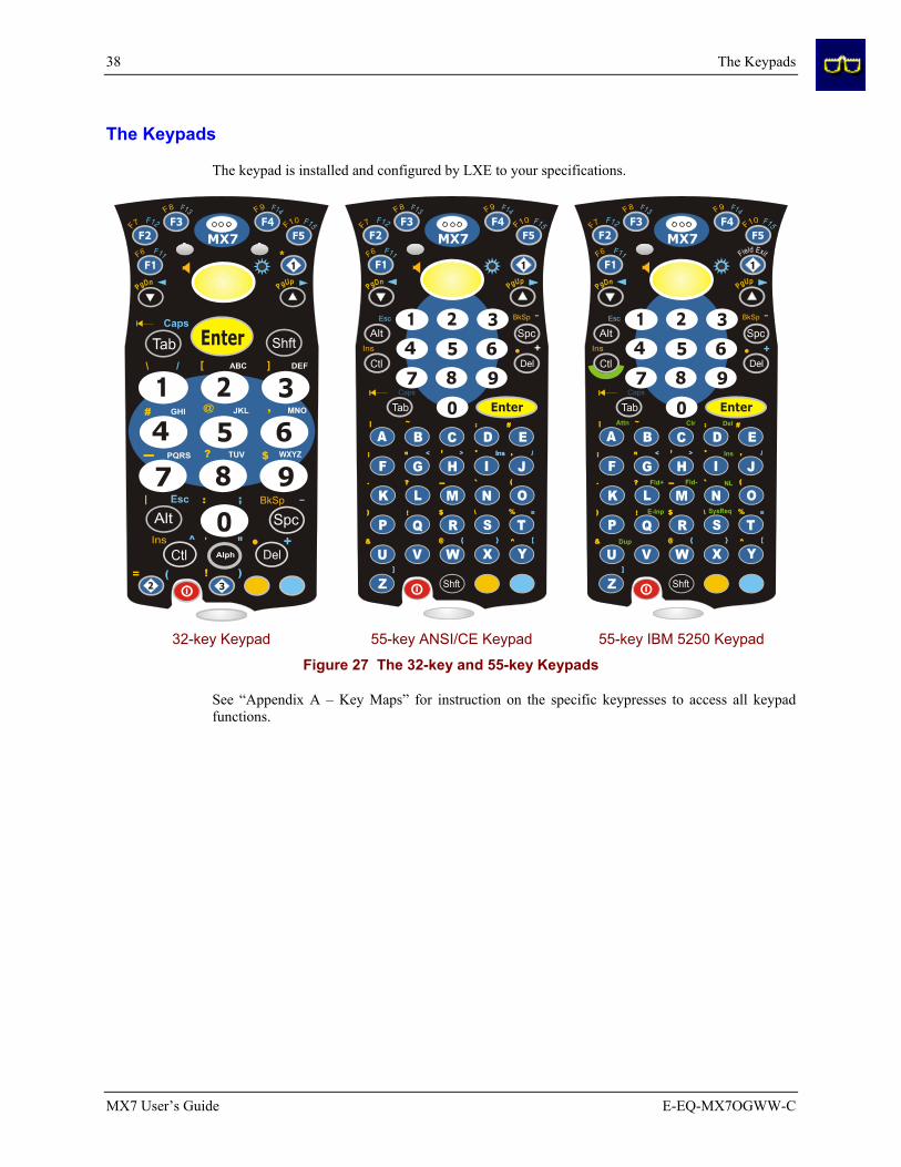
The keypad is installed and configured by LXE to your specifications.
32-key Keypad 55-key ANSI/CE Keypad 55-key IBM 5250 Keypad
Figure 27 The 32-key and 55-key Keypads
See “Appendix A – Key Maps” for instruction on the specific keypresses to access all keypad functions.

The Keypads 39
E-EQ-MX7OGWW-C MX7 User’s Guide
LED Indicators
System Status The System Status LED is located at the top left of the keypad, above the Scan button.
When the LED is . . . The Status is . . . Comment
Blinking Red Power Fail
Replace the main battery with a fully charged main battery.
Or
Connect the MX7 to external AC power (to allow the internal charger to charge the main battery).
Steady Red Main Battery Low Low Battery Warning. Replace the main battery with a fully charged main battery.
Blinking Green Display Off No user intervention required.
No Color Good No user intervention required.
Scan Status The Scan Status LED is located below the MX7 keypad.
When the Scan Status LED is . . . The Status is . . .
Steady Green Good Scan
Steady Red Scan in Progress
No Color Scanner/Imager ready for use.
Alpha Mode (32-key Alph Key) The Alpha Mode LED is located below the <F4> key on the 32-key keypad.
LED functions outlined in previous sections titled “System Status LED” and “Scanner LED” are the same for the 32-key mobile device.
When the Alph LED is . . . The Status is . . .
Steady Green Device is in “Alpha” character input mode.
No Color Device is in “Numeric” key input mode.

40 The Keypads
MX7 User’s Guide E-EQ-MX7OGWW-C
Standard Keys
Scan The integrated scanner scans only when the Scan button is pressed (or when the scan trigger is pressed on the optional trigger handle).
Enter The Enter key is used to confirm a forms entry or to transmit information. How it is used is determined by the application running on the mobile device.
Diamond The Diamond key(s) can be programmed to duplicate a single keypress (as defined by Windows CE) with the exception of the Shift, Alt and Ctrl/Ctl key.
Numeric The number keys are used to add numbers to data entry fields.
Alpha The alpha keys are used to add letters and characters to data entry fields.
Space The Spc key adds a space to the line of data on the display. This function is similar to a regular keyboard’s Spacebar. Note that the Spc key only stays active for one keystroke.
Function Keys
Sticky Keys The Sticky Key feature allows the user to activate multi-keypress combinations with one finger. A sticky key function is similar to the Caps Lock key function on a desktop computer keyboard.
Ctl / Ctrl (Control key)
/ A Control sticky keypress stays active until the Control key is pressed again. The Control key enables the control functions of the keypad. This function is similar to a regular keyboard’s Control key. Each time you need to use a Control function, you need to press the Ctl / Ctrl key before pressing the desired key.
Alt (Alternate key)
An Alt sticky keypress stays active until the Alt key is pressed again. The Alt key enables the alternate functions of the keypad. This function is similar to a regular keyboard’s Alt key. Each time you need to use an alternate function, you need to press the Alt key before pressing the desired key.
Shft (Shift key)
A Shift keypress ends a sticky key function. The Shft key enables the shifted functions of the keypad. This function is similar to a regular keyboard’s Shift key. Note that the Shift key only stays active for one keystroke. Each time you need to use a Shifted function, you need to press the Shft key before pressing the desired key.
When the Shft key is pressed the next key is determined by the major key legends, i.e., the alpha keys display lower case letters -- when CAPS is On alpha characters are capitalized. For example, when CAPS is On and the Shft key and the G key are pressed, a lower case g is displayed.

The Keypads 41
E-EQ-MX7OGWW-C MX7 User’s Guide
Orange and Blue Keys
/ The Orange and Blue keys are sticky keys that, when tapped, activate the second functions of the keypad. Printed above many keys are small characters, in either orange (on the left side of the key) or blue (on the right side of the key), that represent the second function of that key. Using the sticky key activates the second key function.
Note that the blue and orange sticky keys only stay active for one keystroke. Each time you need to activate a second function you must press the Orange or Blue key. To cancel a sticky key function before pressing another key, press the same sticky key again.
Orange Key
Tap the Orange key to enter “orange” mode. Tap it again to cancel “orange” mode.
If you were in “blue” mode before you pressed the Orange key, blue mode is cancelled and you enter Orange mode.
Blue Key Tap the Blue key to enter “blue” mode. Tap it again to cancel “blue” mode.
If you were in “orange” mode before you pressed the Blue key, orange mode is cancelled and you enter Blue mode.
Field Exit
The Diamond 1 key can be programmed as a Field Exit key. The Field Exit key is used to exit an input field. If the field is an Auto Enter field, the auto transmit function is activated. Refer to the “Mappable Diamond Keys” section for instruction.
IBM 5250 specific keypad only. A Control sticky keypress stays active until the Control key is pressed again. The Control key enables the control functions of the keypad. This function is similar to a regular keyboard’s Control key. Each time you need to use a Control function, you need to press the Ctl key before pressing the desired key.
Note the green highlight on the Control key and the 5250 commands highlighted in green on the 5250 keypad overlay.

42 The Keypads
MX7 User’s Guide E-EQ-MX7OGWW-C
Mode Key Functions
CapsLock Mode
This function is similar to a regular keyboard’s CapsLock key. Note that the CapsLock mode stays active until the CapsLock key sequence is pressed again. Each time you need to use a Caps function, you need to press the Caps key sequence first. To cancel a CapsLock function press the Caps key sequence again.
The CapsLock key sequence is Blue key then the <Tab> key.
55-Key Keypad
• No CapsLock AND No Shift keypress – result is a lowercase letter.
• CapsLock OR Shift – result is an uppercase letter.
• CapsLock AND Shift keypress – result is a lowercase letter.
Visual Cue: A Capital A is displayed in the taskbar when the device is in CapsLock mode or the Caps Key has been pressed and the next key (to be capitalized) has not been pressed.
32-Key Keypad
Example: 2 B or Not 2 B To put the number 2 in a text entry field: Tap the <2> key once.
To put a lowercase “b” in a text field: Tap the <Alph> key, then tap the <2> key twice.
To put an uppercase “B” in a text field: Tap the <Alph> key, tap the <Shft> key or the <CapsLock> key, then tap the <2> key twice.
To enter a string of letters in a text field, tap the <Alph> key to toggle it On. It remains active until it is tapped again and toggled off.
To enter a string of numbers in a text field, make sure the <Alph> key is toggled off.

The Keypads 43
E-EQ-MX7OGWW-C MX7 User’s Guide
Mappable Diamond Keys The Diamond keys can be programmed to perform specific functions. For example, using this Settings option, you could set the Diamond 1 key to function as an ESC key. Setting the Diamond 1 key to function as an ESC key does not disable the function of the “standard” ESC key sequence (Blue+Alt).
55 Key Diamond 1 32 Key Diamond 1 32 Key Diamond 2 / Diamond 3
Figure 28 Mappable Diamond Keys
The Diamond 1 key defaults to Field Exit on both keypads. All other Diamond keys and Diamond Sticky keys have no assigned default value (i.e. their default value is <no key>).
To edit the diamond key parameters, tap | Settings | Control Panel | Mappable Keys tab. Change the parameter values using the drop down list and tap OK to save the changes. The change takes effect immediately.
See Also: Appendix A “Key Maps”.
55 Key Keypad The user can program the following key combinations using the Diamond 1 key:
+ + +
e.g. ESC (Blue+Alt)
e.g. Home (Shft+Down Arrow)
e.g. BackTab (Orange+Tab)
e.g. Insert (Blue+I)
Any combination of “standard” keypresses can be used.

44 The Keypads
MX7 User’s Guide E-EQ-MX7OGWW-C
32 Key Keypad The user can program the following key combinations using the Diamond keys:
user defined without using a sticky key + asterisk (*) +
user defined without using a sticky key + equal sign (=) open parenthesis
(
user defined without using a sticky key +
exclamation mark (!)
closed parenthesis )
Note: Refer to the “MX7 Reference Guide” before mapping the Diamond keys. The Reference Guide also contains instructions for the Key Map Utility for the keypad.

Batteries 45
E-EQ-MX7OGWW-C MX7 User’s Guide
Batteries
Note: New batteries must be charged prior to use. If the main battery and backup battery are depleted, the mobile device reverts to factory default values. Wireless configuration parameters will need to be re-entered after reverting to factory default values. The backup battery is continually recharged by the main battery pack.
The mobile device is designed to work with a 2200 mAh Lithium-Ion (Li-ion) battery from LXE. Under normal conditions it should last approximately eight to ten hours before requiring a recharge. During very heavy scanner or RF transmitter use, the operating time of the battery may be less. The operating system keeps date and time valid for a minimum of four days using a fully charged backup battery and a main battery pack installed that has reached the Low Warning point.
Battery Pack Model Number – 159904-0001 / MX7A380BATT
Figure 29 Lithium Ion Battery Pack
1. Contacts, Battery Charging
2. Retaining Clip
3 Tab
Main Battery
CAUTION
RISK OF EXPLOSION IF BATTERY IS REPLACED BY AN INCORRECT TYPE.
DISPOSE OF USED BATTERIES ACCORDING TO THE INSTRUCTIONS.
ATTENTION
II y a danger d’explosion s’il y a remplacement incorrect de la batterie.
Remplacer uniquement avec une batterie du même type ou d’un type equivalent recommandé par le constructeur. Mettre au rebut les batteries usagées conformément aux instructions du fabricant.
The main battery has a rugged plastic enclosure that is designed to withstand the ordinary rigors of an industrial environment. Exercise care when transporting the main battery making sure it does not come in contact with excessive heat or any power source other than an MX7 MultiCharger or the mobile device.
A new main battery pack can be fully charged in 6 hours when it is in an MX7 connected to AC power and 3.5 hours when it is in the MX7 multicharger.
Backup Battery The internal 50mAh Nickel Cadmium (NiCd) backup battery provides power to the device for a short amount of time when the main battery has been depleted, removed or has failed. The backup battery status and conditioning is available using | Settings | Control Panel | Battery. The backup battery is charged by the main battery pack only. If the backup battery is completely discharged, it may take up to 5 hours to recharge.

46 Batteries
MX7 User’s Guide E-EQ-MX7OGWW-C
Backup battery replacement is performed by LXE.
Note: An uninterrupted external power source (wall AC adapters) transfers power to the computer’s internal charging circuitry which, in turn, recharges the main battery and backup battery. Frequent connection to an external power source, if feasible, is recommended to maintain backup battery charge status as the backup battery cannot be recharged by a dead or missing main battery.
Battery Hotswapping Important: When the backup battery power is Low or Very Low ( | Settings | Control Panel | Power | Battery tab) connect the AC adapter to the MX7 before replacing the main battery pack.
Replace the main battery pack after first pressing the Power key and placing the MX7 in Suspend Mode. LXE recommends any work in progress be saved prior to replacing the main battery pack.
Simply replace the discharged main battery with a fully-charged main battery. A fully charged backup battery will retain data during a main battery hotswap for 5 minutes.
Warning: Never replace the main battery in a hazardous location.

Battery Chargers 47
E-EQ-MX7OGWW-C MX7 User’s Guide
Battery Chargers
The MX7 Multi-Charger is not approved for use in a Hazardous Location.
Charge Main Battery in MX7 Multi-Charger The main battery pack can be charged while it is in the MX7 (connected to an AC power supply) or while it is in the LXE MX7 Multi-Charger.
Please refer to the “MX7 Multi-Charger User’s Guide” for instruction.
The multi-charger requires an external power source before battery pack charging/analyzing can commence.
The external Power Supply for the Multi-charger is shipped with the multi-charger.
MX7 Multi-Chargers are not approved for use in Hazardous Locations.
1 Front 4 Power Connection
2 Battery Charging Pocket 5 LCD Display
3 LED Indicators
Figure 30 MX7 Multi-Charger / Analyzer

48 Battery Chargers
MX7 User’s Guide E-EQ-MX7OGWW-C
Figure 31 Insert Battery Pack in Charging Pocket
1. Battery Well
2. Retaining Clip
3. Battery Charging Contacts
Lower the battery pack straight into the battery charger pocket and push it down firmly. Do not "slam" the battery into the charging cup or drop it into the cup.
Failure to follow these instructions can result in damage to the main battery or the charger.
Please refer to the multi-charger user's guide for technical information and operating instructions.

Passive Vehicle Mount Cradle 49
E-EQ-MX7OGWW-C MX7 User’s Guide
Passive Vehicle Mount Cradle
A passive vehicle mount cradle is available for the MX7. The cradle restrains the MX7. The passive cradle does not have an external device connector e.g. power/RS-232 cable. Wireless client interaction is available as long as the mobile device has sufficient energy in the MX7 main battery pack and a clear signal path.
The cradle is lined with strips of hook-and-loop fabric to ensure a snug fit between the MX7 and the inside of the cradle.
The vehicle cradle should be mounted in an area in the vehicle where it:
• Does not obstruct the driver's vision or safe vehicle operation.
• Will be protected from rain or inclement weather.
• Will be protected from extremely high concentrations of dust or wind-blown debris.
• Can be easily accessed by a user seated in the driver's seat.
There are two mounting options for the cradle:
• U-bracket mounting
• RAM ball cylinder mounting
Before installation begins, verify you have the applicable vehicle mounting bracket assembly components necessary for your mount type, as shown in the section titled “Assembly Components”.
Do not slide the MX7 into the passive cradle until the cradle is securely fastened to the vehicle.

50 Passive Vehicle Mount Cradle
MX7 User’s Guide E-EQ-MX7OGWW-C
Cradle Assembly Components
Note: Bolts, washers, and wrench needed when attaching the mobile device to the vehicle are not supplied by LXE.
U-Bracket
Figure 32 Passive Vehicle Mount Cradle and U-Bracket
U-Bracket Footprint
Not To Scale
Figure 33 U-Bracket Mounting Footprint
Note: LXE does not supply the bolts or washers needed when mounting the cradle assembly to the vehicle chassis. LXE recommends using bolts with a maximum 10/32” (0.3125) diameter

Passive Vehicle Mount Cradle 51
E-EQ-MX7OGWW-C MX7 User’s Guide
RAM Ball and Cylinder
Figure 34 Passive Vehicle Mount Cradle / RAM Ball Assembly
Figure 35 RAM Bracket Components
Mount the cradle U-bracket to the upper RAM ball assembly with the bolts, washers and nuts supplied by LXE. Qty 4 - Hex Cap 1/4-20 x 3/4 bolts Qty 4 - 1/4 flat washer Qty 4 - 1/4-20 nylon insert lock nuts

52 Passive Vehicle Mount Cradle
MX7 User’s Guide E-EQ-MX7OGWW-C
RAM Assembly Footprint
Not To Scale
Figure 36 RAM Assembly Footprint
Note: LXE does not supply the bolts or washers needed when mounting the cradle assembly to the vehicle chassis. LXE recommends using bolts with a maximum 10/32” (0.3125) diameter.
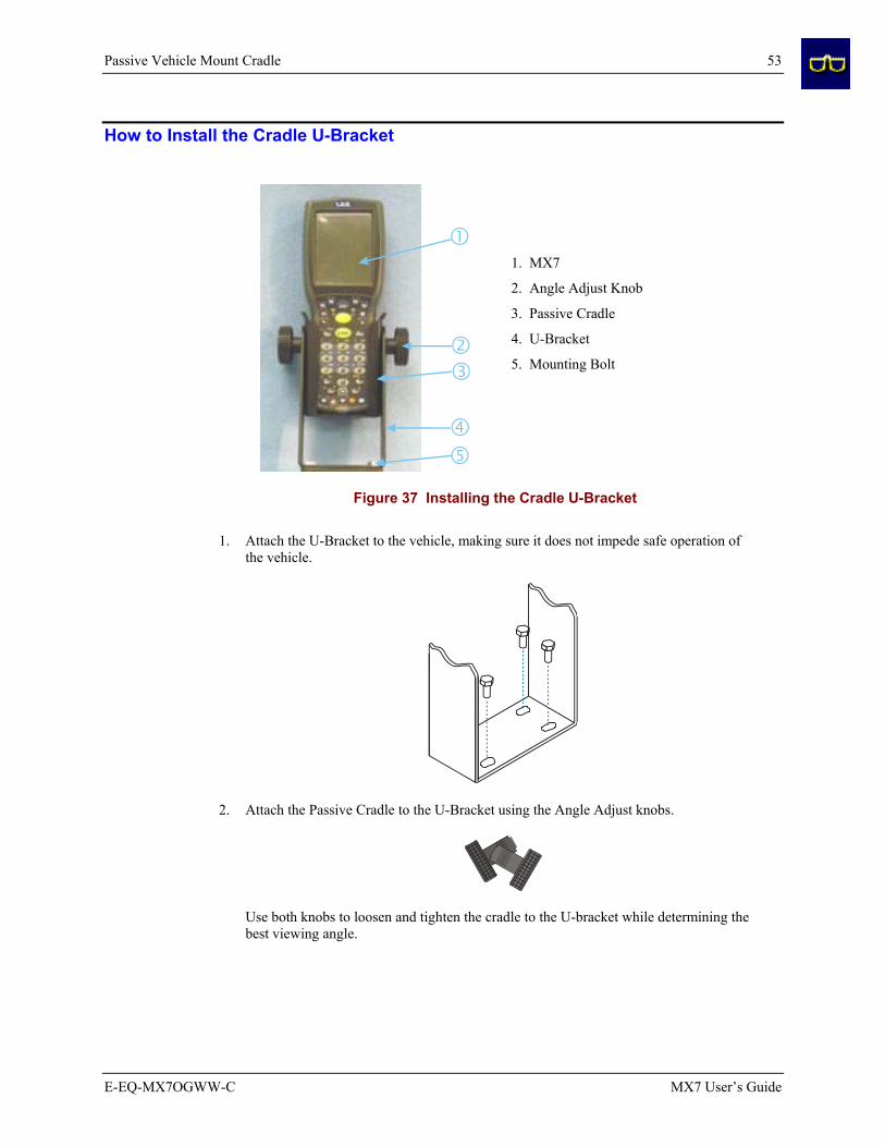
Passive Vehicle Mount Cradle 53
E-EQ-MX7OGWW-C MX7 User’s Guide
How to Install the Cradle U-Bracket
1. MX7
2. Angle Adjust Knob
3. Passive Cradle
4. U-Bracket
5. Mounting Bolt
Figure 37 Installing the Cradle U-Bracket
1. Attach the U-Bracket to the vehicle, making sure it does not impede safe operation of the vehicle.
2. Attach the Passive Cradle to the U-Bracket using the Angle Adjust knobs.
Use both knobs to loosen and tighten the cradle to the U-bracket while determining the best viewing angle.
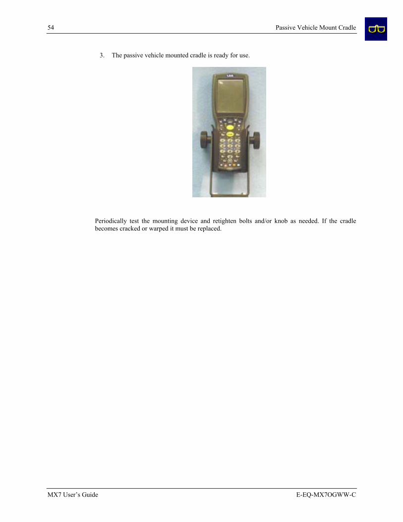
54 Passive Vehicle Mount Cradle
MX7 User’s Guide E-EQ-MX7OGWW-C
3. The passive vehicle mounted cradle is ready for use.
Periodically test the mounting device and retighten bolts and/or knob as needed. If the cradle becomes cracked or warped it must be replaced.

Passive Vehicle Mount Cradle 55
E-EQ-MX7OGWW-C MX7 User’s Guide
How To Install the RAM Bracket
1. MX7
2. Angle Adjust Knobs
3. Passive Cradle
4. U-Bracket
5. Mounting Hex Bolt
6. Upper RAM Ball Assembly
7. Arm
8. Thumbscrew
9. Lower RAM Ball Assembly
Figure 38 Installing the RAM Assembly
1. Attach the lower RAM ball assembly to the vehicle, making sure it does not impede safe operation of the vehicle.
2. Fasten the upper RAM ball assembly to the base of the U-bracket using the supplied bolts, washers and screws.

56 Passive Vehicle Mount Cradle
MX7 User’s Guide E-EQ-MX7OGWW-C
3. Loosen the turnscrew on the RAM arm, place the lower socket over the vehicle mount RAM ball, then the other arm socket over the RAM ball on the U-bracket.
4. Tighten the arm turnscrew until the U-bracket is secured to the RAM arm and the vehicle.
5. Attach the Passive Cradle to the U-Bracket using the Angle Adjust knobs.
Use both knobs to loosen and tighten the cradle to the U-bracket while determining the best viewing angle.
6. The passive vehicle mounted cradle is ready for use.

Passive Vehicle Mount Cradle 57
E-EQ-MX7OGWW-C MX7 User’s Guide
Periodically test the mounting device and retighten bolts and/or knob as needed. If the cradle becomes cracked or warped it must be replaced.

58 Passive Vehicle Mount Cradle
MX7 User’s Guide E-EQ-MX7OGWW-C

E-EQ-MX7OGWW-C MX7 User’s Guide
Appendix A Key Maps
Introduction
Remember :
“Sticky” keys are also known as “second” function keys.
Ctl/Ctrl, Alt, Shft, Blue and Orange keys are “sticky keys”. Sticky keys do not need to be held down before pressing the next (or desired) key. It is valid to use combined modifiers on specific keys.
Note: The key mapping in this appendix relates to the physical keypad. See section titled “Input Panel” for the Virtual (or Soft) Keypad used with the stylus.
55-Key Alphanumeric Keymaps
ANSI / CE Keypad When using a sequence of keys that includes a sticky key, press the sticky key first, release it, then press the rest of the key sequence.
When using a sequence of keys that includes the Orange or Blue keys, press the color key first then the rest of the key sequence.
Alphabetic keys default to lower case letters. Press the Shft key, then the alphabetic key for an uppercase letter.
When the computer boots, the default condition of Caps (or CapsLock) is Off. The Caps (or CapsLock) condition can be toggled with Blue plus Tab key sequence.
Press These Keys and Then … To Get This MX7 Key / Function Blue Orange Ctl Alt Shft Caps
Lock Press This Key
Power / Suspend Power 1
Field Exit (default VK_PAUSE)
MAP=Mappable MAP MAP MAP Diamond#1
Volume Adjust Mode x
x
Scan Key 2
or V
1 Tapping the Power key when in any sticky mode (Blue, Orange, Shift, etc) either turns the device On (when Off) or places it in Suspend (when active). 2 Orange+Scan (and Blue+V) enters Volume Adjust Mode. Use Up Arrow and Down Arrow to adjust volume. Press any other key but Up Arrow or Down Arrow to exit Adjust Mode.
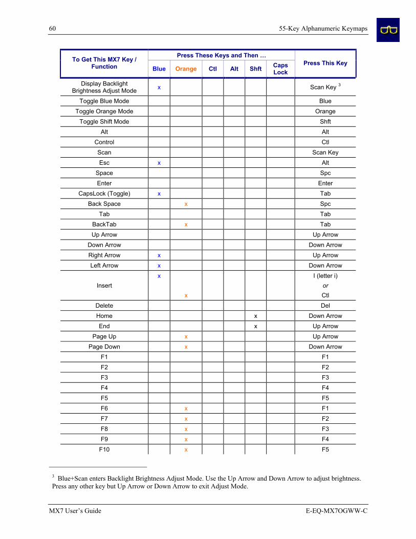
60 55-Key Alphanumeric Keymaps
MX7 User’s Guide E-EQ-MX7OGWW-C
Press These Keys and Then … To Get This MX7 Key / Function Blue Orange Ctl Alt Shft Caps
Lock Press This Key
Display Backlight Brightness Adjust Mode x Scan Key 3
Toggle Blue Mode Blue
Toggle Orange Mode Orange
Toggle Shift Mode Shft
Alt Alt
Control Ctl
Scan Scan Key
Esc x Alt
Space Spc
Enter Enter
CapsLock (Toggle) x Tab
Back Space x Spc
Tab Tab
BackTab x Tab
Up Arrow Up Arrow
Down Arrow Down Arrow
Right Arrow x Up Arrow
Left Arrow x Down Arrow
Insert x
x
I (letter i)
or Ctl
Delete Del
Home x Down Arrow
End x Up Arrow
Page Up x Up Arrow
Page Down x Down Arrow
F1 F1
F2 F2
F3 F3
F4 F4
F5 F5
F6 x F1
F7 x F2
F8 x F3
F9 x F4
F10 x F5
3 Blue+Scan enters Backlight Brightness Adjust Mode. Use the Up Arrow and Down Arrow to adjust brightness. Press any other key but Up Arrow or Down Arrow to exit Adjust Mode.

55-Key Alphanumeric Keymaps 61
E-EQ-MX7OGWW-C MX7 User’s Guide
Press These Keys and Then … To Get This MX7 Key / Function Blue Orange Ctl Alt Shft Caps
Lock Press This Key
F11 x F1
F12 x F2
F13 x F3
F14 x F4
F15 x F5
F16 x F1
F17 x F2
F18 x F3
F19 x F4
F20 x F5
F21 x x F1
F22 x x F2
F23 x x F3
F24 x x F4
a A
b B
c C
d D
e E
f F
g G
h H
i I
j J
k K
l L
m M
n N
o O
p P
q Q
r R
s S
t T
u U
v V
w W
x X
y Y
z Z

62 55-Key Alphanumeric Keymaps
MX7 User’s Guide E-EQ-MX7OGWW-C
Press These Keys and Then … To Get This MX7 Key / Function Blue Orange Ctl Alt Shft Caps
Lock Press This Key
A x A
B x B
C x C
D x D
E x E
F x F
G x G
H x H
I x I
J x J
K x K
L x L
M x M
N x N
O x O
P x P
Q x Q
R x R
S x S
T x T
U x U
V x V
W x W
X x X
Y x Y
Z x Z
1 1
2 2
3 3
4 4
5 5
6 6
7 7
8 8
9 9
0 0
. period or
. (period)
x x
DEL or K
< x G
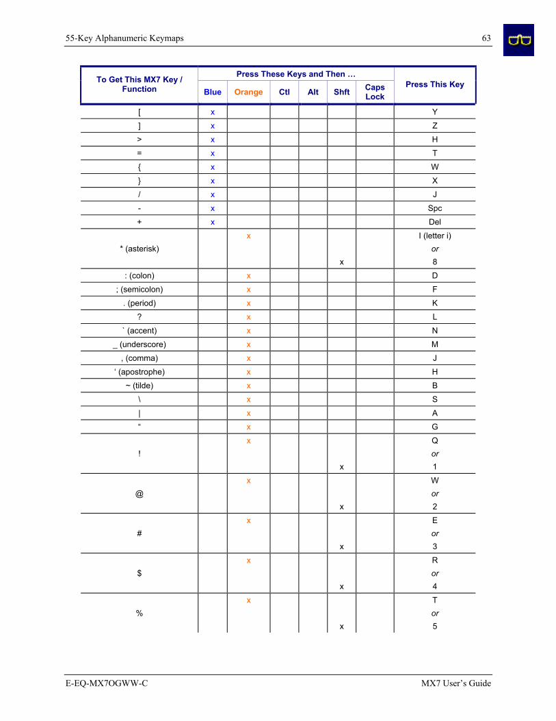
55-Key Alphanumeric Keymaps 63
E-EQ-MX7OGWW-C MX7 User’s Guide
Press These Keys and Then … To Get This MX7 Key / Function Blue Orange Ctl Alt Shft Caps
Lock Press This Key
[ x Y
] x Z
> x H
= x T
{ x W
} x X
/ x J
- x Spc
+ x Del
* (asterisk) x
x
I (letter i)
or 8
: (colon) x D
; (semicolon) x F
. (period) x K
? x L
` (accent) x N
_ (underscore) x M
, (comma) x J
‘ (apostrophe) x H
~ (tilde) x B
\ x S
| x A
“ x G
! x
x
Q or 1
@ x
x
W or 2
# x
x
E or 3
$ x
x
R or 4
% x
x
T or 5

64 55-Key Alphanumeric Keymaps
MX7 User’s Guide E-EQ-MX7OGWW-C
Press These Keys and Then … To Get This MX7 Key / Function Blue Orange Ctl Alt Shft Caps
Lock Press This Key
^ x
x
Y or 6
& x
x
U or 7
( x
x
O or 9
) x
x
P or
0 (zero)
5250 Key Map for the 55-Key Keypad Legend ........................Explanation.........................Key Sequence Attn ..............................Attention...............................Ctl + A Clr ................................Clear .....................................Ctl + C Del ...............................Delete ...................................Ctl + D Dup ..............................Duplicate ..............................Ctl + U E-Inp ............................Erase Input ...........................Ctl + Q Field Exit .....................Enter .....................................Diamond 1 Fld –.............................Field Minus ..........................Ctl + M Fld + ............................Field Plus..............................Ctl + L Ins ................................Insert ....................................Ctl + I NL................................New Line..............................Ctl + N SysReq.........................System .................................Ctl + S
Please refer to the “RFTerm Reference Guide” for further information about 5250 key functions on the mobile device.

32-Key Numeric-Alpha Keypad 65
E-EQ-MX7OGWW-C MX7 User’s Guide
32-Key Numeric-Alpha Keypad
When using a sequence of keys that require an alpha key, first press the Alph key. Use the Shft sticky key or the Caps key sequence (Blue+Tab) for upper case alphabetic characters.
Pressing the Alph key forces “Alpha” mode for the 2,3,4,5,6,7,8, and 9 keys. The 1 and 0 keys continue to place a 1 and 0 into the text field.
To create a combination of numbers and letters before pressing Enter, remember to tap the Alph key to toggle between Alpha and Numeric mode.
When using a sequence of keys that do not include the Alph key but does include a sticky key, press the sticky key first then the rest of the key sequence.
Press These Keys and Then … To Get This MX7 Key / Function Blue Orange Ctl Alt Shft Alpha
Press This Key
Power / Suspend Power 4
Field Exit (default VK_PAUSE) MAP MAP
Diamond#1 MAP=Mappable
= or (
x
x
MAP Diamond#2
Default is MAP MAP=Mappable
! or )
x
x
MAP Diamond#3
Default is MAP MAP=Mappable
Volume Adjust Mode x Scan Key 5
Display Backlight Brightness Adjust Mode x Scan Key 6
Toggle Blue Mode Blue
Toggle Orange Mode Orange
Toggle Shift Mode Shft
Toggle Alpha Mode Alph Alt Mode Alt
Control Mode Ctrl
Scan Mode Scan Key
Esc x Alt
Space Spc
Enter Enter
CapsLock (Toggle) x Tab
Back Space x Spc
Tab Tab
4 Tapping the Power key when in any sticky mode (Blue, Orange, Shift, etc) either turns the device On (when Off) or places it in Suspend (when active). 5 Orange+Scan enters Volume Adjust Mode. Use Up Arrow and Down Arrow to adjust volume. Press any other key but Up Arrow or Down Arrow to exit Adjust Mode. 6 Blue+Scan enters Backlight Brightness Adjust Mode. Use the Up Arrow and Down Arrow to adjust brightness. Press any other key but Up Arrow or Down Arrow to exit Adjust Mode.

66 32-Key Numeric-Alpha Keypad
MX7 User’s Guide E-EQ-MX7OGWW-C
Press These Keys and Then … To Get This MX7 Key / Function Blue Orange Ctl Alt Shft Alpha
Press This Key
BackTab x Tab
Up Arrow Up Arrow
Down Arrow Down Arrow
Right Arrow x Up Arrow
Left Arrow x Down Arrow
Insert x Ctrl
Delete Del
Home x Down Arrow
End x Up Arrow
Page Up x Up Arrow
Page Down x Down Arrow
F1 F1
F2 F2
F3 F3
F4 F4
F5 F5
F6 x F1
F7 x F2
F8 x F3
F9 x F4
F10 x F5
F11 x F1
F12 x F2
F13 x F3
F14 x F4
F15 x F5
F16 x F1
F17 x F2
F18 x F3
F19 x F4
F20 x F5
F21 x x F1
F22 x x F2
F23 x x F3
F24 x x F4
a x 2
b x 22
c x 222
d x 3
e x 33

32-Key Numeric-Alpha Keypad 67
E-EQ-MX7OGWW-C MX7 User’s Guide
Press These Keys and Then … To Get This MX7 Key / Function Blue Orange Ctl Alt Shft Alpha
Press This Key
f x 333
g x 4
h x 44
i x 444
j x 5
k x 55
l x 555
m x 6
n x 66
o x 666
p x 7
q x 77
r x 777
s x 7777
t x 8
u x 88
v x 888
w x 9
x x 99
y x 999
z x 9999
A x x 2
B x x 22
C x x 222
D x x 3
E x x 33
F x x 333
G x x 4
H x x 44
I x x 444
J x x 5
K x x 55
L x x 555
M x x 6
N x x 66
O x x 666
P x x 7
Q x x 77
R x x 777
S x x 7777

68 32-Key Numeric-Alpha Keypad
MX7 User’s Guide E-EQ-MX7OGWW-C
Press These Keys and Then … To Get This MX7 Key / Function Blue Orange Ctl Alt Shft Alpha
Press This Key
T x x 8
U x x 88
V x x 888
W x x 9
X x x 99
Y x x 999
Z x x 9999
1 1
2 2
3 3
4 4
5 5
6 6
7 7
8 8
9 9
0 0
. (period) x DEL
< x 7
[ x
x
2 or 2
] x
x
3 or 3
> x 8
= x Diamond#2
{ x 4
} x 5
/ x 1
- x Spc
+ x Del
* (asterisk) x
x
8 or
Diamond#1
: (colon) x 0
; (semicolon) x 0
. (period) x Del
? x 8
` (accent) x 6
_ (underscore) x 7

32-Key Numeric-Alpha Keypad 69
E-EQ-MX7OGWW-C MX7 User’s Guide
Press These Keys and Then … To Get This MX7 Key / Function Blue Orange Ctl Alt Shft Alpha
Press This Key
, (comma) x 6
‘ (apostrophe) x Alph
~ (tilde) x 9
\ x 1
| x Alt
“ x Alph
! x
x
Diamond#3
or 1
@ x
x
2 or 5
# x
x
3 or 4
$ x
x
9 or 4
% x 5
^ x
x
6 or
Ctrl
& x 7
( x
x
Diamond#2
or 9
) x
x
Diamond#3
or 0 (zero)

70 32-Key Numeric-Alpha Keypad
MX7 User’s Guide E-EQ-MX7OGWW-C
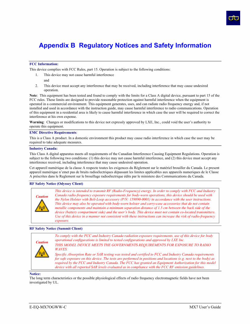
E-EQ-MX7OGWW-C MX7 User’s Guide
Appendix B Regulatory Notices and Safety Information
FCC Information: This device complies with FCC Rules, part 15. Operation is subject to the following conditions:
1. This device may not cause harmful interference and 2. This device must accept any interference that may be received, including interference that may cause undesired
operation. Note: This equipment has been tested and found to comply with the limits for a Class A digital device, pursuant to part 15 of the FCC rules. These limits are designed to provide reasonable protection against harmful interference when the equipment is operated in a commercial environment. This equipment generates, uses, and can radiate radio frequency energy and, if not installed and used in accordance with the instruction guide, may cause harmful interference to radio communications. Operation of this equipment in a residential area is likely to cause harmful interference in which case the user will be required to correct the interference at his own expense. Warning: Changes or modifications to this device not expressly approved by LXE, Inc., could void the user’s authority to operate this equipment.
EMC Directive Requirements: This is a Class A product. In a domestic environment this product may cause radio interference in which case the user may be required to take adequate measures.
Industry Canada: This Class A digital apparatus meets all requirements of the Canadian Interference Causing Equipment Regulations. Operation is subject to the following two conditions: (1) this device may not cause harmful interference, and (2) this device must accept any interference received, including interference that may cause undesired operation. Cet appareil numérique de la classe A respecte toutes les exigences du Règlement sur le matériel brouiller du Canada. Le present appareil numérique n’emet pas de bruits radioélectriques dépassant les limites applicables aux appareils numeriques de le Classe A préscrites dans le Reglement sur le brouillage radioélectrique édits par le ministere des Communications du Canada.
RF Safety Notice (Odyssey Client)
Caution
This device is intended to transmit RF (Radio-Frequency) energy. In order to comply with FCC and Industry Canada radio-frequency exposure requirements for body-worn operations, this device should be used with the Nylon Holster with Belt-Loop accessory (P/N: 159890-0001) in accordance with the user instructions. This device may also be operated with body-worn holster and carry-case accessories that do not contain metallic components and maintain a minimum separation distance of 1.5 cm between the back side of the device (battery compartment side) and the user’s body. This device must not contain co-located transmitters. Use of this device in a manner not consistent with these instructions can increase the risk of radio-frequency exposure.
RF Safety Notice (Summit Client)
Caution
To comply with the FCC and Industry Canada radiation exposure requirements, use of this device for body operational configurations is limited to tested configurations and approved by LXE Inc. THIS MODEL DEVICE MEETS THE GOVERNMENTS REQUIREMENTS FOR EXPOSURE TO RADIO WAVES. Specific Absorption Rate or SAR testing was tested and certified to FCC and Industry Canada requirements for safe exposure on this device. The tests are performed in positions and locations (e.g. next to the body) as required by the FCC and Industry Canada. The FCC has granted an Equipment Authorization for this model device with all reported SAR levels evaluated as in compliance with the FCC RF emission guidelines.
Notice: The long term characteristics or the possible physiological effects of radio frequency electromagnetic fields have not been investigated by UL.

72 Appendix B Regulatory Notices and Safety Information
MX7 User’s Guide E-EQ-MX7OGWW-C
Li-Ion Battery When disposing of the MX7 main battery, the following precautions should be observed: The battery should be disposed of promptly. The battery should not be disassembled or crushed. The battery should not be heated above 212°F (100°C) or incinerated.
Important: This symbol is placed on the product to remind users to dispose of Waste Electrical and Electronic Equipment (WEEE) appropriately, per Directive 2002-96-EC. In most areas, this product can be recycled, reclaimed and re-used when properly discarded. Do not discard labeled units with trash. For information about proper disposal, contact LXE through your local sales representative, or visit www lxe com.
R&TTE Directive Requirements (Applies only to equipment operated within the EU/EFTA)
Information to User A label on the exterior of the device should resemble one of the labels shown below (the label contains the LXE part number of the installed radio card). The labels shown below and affixed to the device, identify where the device may be used and where its use is restricted. Use of a device is prohibited in countries not listed below or otherwise identified by the label. (May or may not include the 0560 Notifed Body No. Substitute 4 digit Notified Body No. may also be applied.)
Permitted for use in: Austria, Belgium, Denmark, Finland, Germany, Greece, Hungary, Iceland, Italy, Ireland, Liechtenstein, Luxembourg, Netherlands, Norway, Portugal, Spain, Sweden, Switzerland, and the United Kingdom
Permitted for use in France.
MX7 Approvals/Standards
Product EMI / EMC Standards Safety Standards MX7 with 802.11b/g Radio FCC Part 15 Subpart B, Class A
EN 55022 Class A (CISPR 22) EN 55024:1998 AS/NZS 3548, Class A (CISPR 22)
UL 60950 / CSA C22.2 No. 60950 IEC/EN 60950-1
CDRH: 21 CFR 1040.10 IEC/EN 60825-1
Transceiver:
Transceiver RF (2.4 GHz) standards RF Safety Standards MX7 with 802.11b/g [Odyssey Client]
FCC Part 15, subpart C Industry Canada RSS 210 ETSI 300 328
FCC O.E.T. Bulletin 65 Industry Canada RSS 102
MX7 with 802.11b/g [Summit Client]
FCC Part 15.247, Subpart C FCC Bulletin OET-65 EN 300 328
IC-RSS 210 IC-RSS 102
Unlicensed Operation Unlicensed Operation
Requires License for Outdoor Use
Republic of Singapore - LXE Dealer License Number DA103458 complies with IDA Standards.

Appendix B Regulatory Notices and Safety Information 73
E-EQ-MX7OGWW-C MX7 User’s Guide
LXE 802.11b/g WLAN Declaration of Conformity (Odyssey Client)
DECLARATION OF CONFORMITY according to:
the R&TTE Directive; 99/5/EEC
The EMC Directive; 89/336/EEC The Low Voltage Directive; 73/23/EEC and the Marking Directive; 93/68/EEC
Type of Equipment: DSSS 2.4GHz WLAN Brand Name or Trademark: LXE
Type Designation: MX7 with 802.11b/g WLAN Manufacturer: LXE Inc.
Address: 125 Technology Parkway Norcross, GA 30092 USA
The following harmonized European Norms have been applied: EMC Standards:
EN 301 489-1: 07-2000 Electromagnetic compatibility and Radio spectrum Matters (ERM); ElectroMagnetic Compatibility (EMC) standard for radio equipment and services; Part 1: Common technical requirements
EN 301 489-17:07-2000 Electromagnetic compatibility and Radio spectrum Matters (ERM); ElectroMagnetic Compatibility (EMC) standard for radio equipment and services; Part 17: Specific conditions for Wideband data and HIPERLAN equipment
EN 55022: 1998 Limits and methods of measurement of radio disturbance characteristics of information technology equipment
Radio Standards: EN 300 328-1 and -2: 2000-7 Radio Equipment and Systems (RES);
Wideband transmission systems; Technical characteristics and test conditions for data transmission equipment operating in the 2.4 GHz ISM band and using spread spectrum modulation techniques
Safety Standard:
EN60950-1: 2001 Safety of information technology equipment, including electrical business equipment
The product carries the CE Mark:
We, LXE Inc., declare that the equipment specified above complies with all Essential Health and Safety Requirements of the above Directives and Standards, as amended.
Date of issue: November 8, 2005
Cyril A. Binnom Jr.EMC Approvals Engineer
LXE Inc. 125 Technology Parkway Norcross, GA 30092-2993 USA ph. 770/447-4224 fax 770/447-6928

74 Appendix B Regulatory Notices and Safety Information
MX7 User’s Guide E-EQ-MX7OGWW-C
LXE 802.11b/g WLAN Declaration of Conformity (Summit Client)
DECLARATION OF CONFORMITY according to Directives:
1999/5/EC
93/68/EEC
Radio Equipment and Telecommunications Terminal Equipment and the mutual recognition of their conformity CE Marking Directive
Type of Equipment:
Brand Name or Trademark: Type Designation:
Manufacturer: Address:
Year of Manufacturer:
Direct Sequence 2.4 GHz Wireless LAN Card LXE LXE 4830 LXE Inc. 125 Technology Parkway Norcross, GA 30092-2993 USA 2006
The following harmonized European Standards, technical specifications, or other normative documents have been applied:
EMC: EN 301 489-1: 07-2000 EN 301-489-17 07-2000 Radio: EN 300 328-1 and -2: 2000-7 Safety: EN 60950-2: 1992 + A1..A4
Electromagnetic compatibility and Radio spectrum Matters (ERM); ElectroMagnetic Compatibility (EMC) standard for radio equipment and services; Part 1: Common technical requirements Electromagnetic compatibility and Radio spectrum Matters (ERM); ElectroMagnetic Compatibility (EMC) standard for radio equipment and services; Part 17: Specific conditions for Wideband data and HIPERLAN equipment Radio Equipment and Systems (RES); Wideband transmission systems; Technical characteristics and test conditions for data transmission equipment operating in the 2,4 GHz ISM band and using spread spectrum modulation techniques Safety of information technology equipment, including electrical business equipment
We, LXE Inc., declare that the equipment specified above complies with all Essential Health and Safety Requirements of the above Directives and Standards, as amended.
Place: LXE Inc., Norcross GA USA C. Binnom Jr. RF Approvals Engineer Date of issue: 14 July 2006
LXE Inc. 125 Technology Parkway Norcross, GA 30092-2993 USA ph. 770/447-4224 fax 770/447-6928

Appendix B Regulatory Notices and Safety Information 75
E-EQ-MX7OGWW-C MX7 User’s Guide
Annex to DoC for LXE 4830
With regard to the use of external antennas
The LXE 4830 can be equipped with external antennas. The antennas listed have been evaluated with the LXE 4830 pursuant to EN 300 328, and therefore meet the definition of ‘dedicated antenna’ per ERC/REC 70-03 Appendix 1 Table 3; thus the requirement set forth in ERC/REC 70-03 , Annex 3 are met by the LXE model 4830 transceiver.
Dedicated Antennas for use with LXE 4830
LXE P/N Antenna Gain Radio Power Level Antenna Description 153180-0001 2.2 dBi 15.8 dBm Omni, for LXE VX-series computers 160952-0001 0 dBi 15.8 dBm Omni, for LXE MX3-series computers 158399-0001 0 dBi 15.8 dBm Omni, for LXE MX5-series computers 159900-0001 0 dBi 15.8 dBm Omni, for LXE MX7-series computers 160019-0001 0 dBi 15.8 dBm Omni, for LXE VX-series computers 160501-0001 0 dBi 15.8 dBm Omni, for LXE HX1-series computers
C. Binnom Jr. RF Approvals Engineer 14 July 2006
LXE Inc. 125 Technology Parkway Norcross, GA 30092-2993 USA ph. 770/447-4224 fax 770/447-6928

76 Appendix B Regulatory Notices and Safety Information
MX7 User’s Guide E-EQ-MX7OGWW-C
A/C Power Supply Safety Statement – MX7
Output Rated 12 VDC, 1.25 A. The LXE-approved AC Power Adapter is only intended for use in a 25°C (77°F) maximum
ambient temperature environment.
Optional A/C Power Supply:
Outside North America, this unit is intended for use with an IEC certified ITE power supply with output rated as stated at the top of this page. (US)
Alimentation c.a. optionnelle: Hors de l'Amérique du Nord, cette unité est conçue pour être utilisée avec une alimentation ITE certifiée CEI de sortie nominale indiquée au haut de cette page. (FR) Valgfrit vekselstrømforsygning Udenfor Nord Amerika er denne enhed udstattet med en IEC (international elektronisk Kommission) udfærdiget med en ITE strømforsygning med strømudgang som fastslået på denne sides begyndelse. (DK) Vaihtoehtoinen vaihtovirran syöttölaite: Pohjois-Amerikan ulkopuolella tämä laite on tarkoitettu käytettäväksi sellaisen IEC:n sertifioiman ITE-tehonsyöttölaitteen kanssa, jonka antoteho on tämän sivun yläosassa esitetyn mukainen. (FI) Optionales Netzteil (Wechselstrom) Außerhalb Nordamerikas sollte diese Einheit über ein der IEC-Norm entsprechendes ITE-Netzteil gespeist werden, und zwar mit einer wie oben auf dieser Seite genannten Ausspeisung. (DE) Προαιρετική Τροφοδοσία Συνεχούς Ρεύματος Εκτός Β. Αμερικής, η μονάδα αυτή προορίζεται για χρήση με ένα τροφοδοτικό ITE πιστοποιημένο κατά IEC με ονομαστική ισχύ όπως δηλώνεται στην αρχή της σελίδας. (GR) Alimentazione opzionale a corrente alternata: Al di fuori dei paesi dell'America del nord, l'unità deve essere impiegata con un dispositivo d'alimentazione per attrezzature informatiche approvato dalla IEC la cui potenza nominale sia pari a quella indicata all'inizio della pagina. (IT) Vekselstrømforsyning (ekstrautstyr): Utenfor Nord-Amerika skal dette produktet brukes med en IEC-sertifisert ITE-strømforsyning med klassifisert effekt som angitt øverst på denne siden. (NO) Fornecimento opcional de CA: Fora dos EUA, esta unidade destina-se a ser usada com dispositivos de fornecimento de corrente ITE com certificação IEC, com a capacidade indicada no topo desta página. (PT) Suministro optativo de corriente alterna Fuera de América del Norte, esta unidad se debe utilizar con un alimentador ITE homologado por la IEC (comisión electrotécnica internacional) con una salida que tenga la calificación que figura en la parte superior de esta página. (ES) Valfri A/C Strömförsörjning Utanför Nordamerika är det meningen att denna enheten används med en IEC-certifierad ITE-strömförsörjare med den uteffekt som anges längst uppe på den här sidan. (SE)
İsteğe Bağlı A/C Güç Kaynağı: Kuzey Amerika dışında, bu ünite, çıkış sınıflandırması bu sayfanın başında belirtilen IEC sertifikalı bir ITE güç kaynağı ile birlikte kullanılmak üzere tasarlanmıştır. (TR) Updated 10/01/2001 Legend: Danish – DK; English – US; Finnish – FI; French- - FR; German – DE; Greek – GR; Italian – IT; Norwegian – NO; Portuguese – PT; Spanish – ES; Swedish – SE; Turkish – TR.

Appendix B Regulatory Notices and Safety Information 77
E-EQ-MX7OGWW-C MX7 User’s Guide
Laser Light Safety Statement Warning:
This product uses laser light. One of the following labels is provided on the scanner. Please read the Caution statement. (US)
Mise én garde: Ce produit utilise un rayon laser. L’une des étiquettes suivantes est apposée sur le scanneur. Veuillez lire l’avertissement qu’elle contient. (FR) Advertência: Este produto usa luz de laser. O scanner contém um dos seguintes avisos. Favor ler o Aviso. (PT) Varning: Denna produkt använder laserljus. En av de nedanstående etiketterna sitter på scannern. Var god läs varningstexten. (SE) Advarsel: Dette produkt anvender laserlys. En af følgende mærkater anvendes på scanneren. Læs venligst sikkerhedsforanstaltningen. (DK) Varoitus: Tämä tuote käyttää laservaloa. Skannerissa on jokin seuraavista tarroista. Lue Huomio-kohta. (FI) Warnung: Dieses Produkt verwendet Laserlicht. Eines der folgenden Etiketten befindet sich auf dem Scanner. Bitte lesen Sie den Gefahrenhinweis. (DE) Attenzione: Questo prodotto utilizza luce laser. Una delle etichette seguenti c’ ubicata sullo scanner. Si raccomanda di leggere con attenzione le avvertenze riportate. (IT) Advarsel: Dette utstyret bruker laserlys. En av følgende etiketter er plassert på scanneren. Les advarselen på etiketten. (NO) Advertencia: Este producto usa luz de láser. Las etiquetas se proveen en la máquina exploradora. Por favor, lea detenidamente la explicación para las precauciones. (ES) Waarschuwing: Dit product gebruikt laserlicht. Een van de volgende labels is op de scanner aangebracht. Lees a.u.b. de waarschuwing onder Oppassen. (NL)
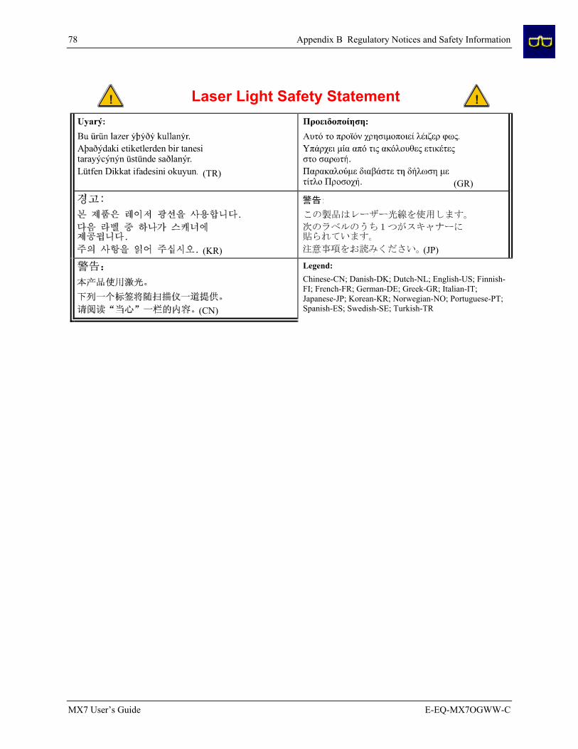
78 Appendix B Regulatory Notices and Safety Information
MX7 User’s Guide E-EQ-MX7OGWW-C
Laser Light Safety Statement
Aþaðýdaki etiketlerden bir tanesitarayýcýnýn üstünde saðlanýr. Lütfen Dikkat ifadesini okuyun. (TR)
(GR)
(KR)
(JP)
(CN)
Legend: Chinese-CN; Danish-DK; Dutch-NL; English-US; Finnish-FI; French-FR; German-DE; Greek-GR; Italian-IT; Japanese-JP; Korean-KR; Norwegian-NO; Portuguese-PT; Spanish-ES; Swedish-SE; Turkish-TR

Appendix B Regulatory Notices and Safety Information 79
E-EQ-MX7OGWW-C MX7 User’s Guide
Labels – MX7 Hand Held Computer [Odyssey Client]

80 Appendix B Regulatory Notices and Safety Information
MX7 User’s Guide E-EQ-MX7OGWW-C
Labels – MX7 Hand Held Computer [Summit Client]

Index 81
E-EQ-MX7OGWW-C MX7 User’s Guide
Index
2nd key function, described ..................................41 32-key Keymap.....................................................65 55-key Keymaps ...................................................59
A AC External Power Supply, How to .....................19 AC Power and LEDs on cradles ...........................................48
AC Power Adapter Assembly ............................................................19
AC Power Scheme................................................35 Accessories Electrostatic Discharge .......................................11 Installing .............................................................11
Alph key Enter a string of letters in a text field ..................42
Alpha Mode LED .................................................39 Alt key function ....................................................40 Alt sticky keypress................................................40 ANSI CE Keypad .................................................23 Audio Cable Install ..................................................................21
Audio Volume settings .........................................36
B Backlight timer .....................................................34 Battery Charge New ........................................................11 Check status ........................................................15 Important...............................................................3
Battery Multi-Charger ..........................................47 Battery Power Scheme..........................................35 Battery, Backup described .............................................................45
Battery, Main ........................................................45 described .............................................................45
Battery, replace .....................................................14
C Cable Printer connection ...............................................21 RS232 connection ...............................................20 USB connection ..................................................20
Calibrate touch screen...........................................33
CapsLock key sequence........................................42 CapsLock mode function ......................................42 Change the Time and Date....................................11 Charger, battery ....................................................47 Cleaning................................................................33 Cold reset, How to ................................................31 Color Display........................................................32 Color displays and backlight timers......................34 Components ............................................................6 Connect External PS .............................................19 Contact LXE .........................................................28 Control sticky keypress.........................................40 Cradle....................................................................49 Ctl key function ....................................................41 Ctrl key function ...................................................40
D Data entry keypad.................................................................25 laser scanner........................................................26 stylus ...................................................................25 virtual keyboard ..................................................27
Data entry .............................................................25 Display..................................................................32 Backlight brightness............................................34
Display and scanner aperture cleaning .................33 Display backlight timer.........................................34
E Edit the button parameters ....................................43 Enter key function.................................................40 Entering Data ........................................................25 Environmental Specifications .................................4 External PS ...........................................................19
F Features...................................................................1 Field Exit key function .........................................41 Forms entry...........................................................25 Function 2nd Key...............................................................41 Alt Key................................................................40 CapsLock Mode ..................................................42 Ctl Key................................................................41

82 Index
MX7 User’s Guide E-EQ-MX7OGWW-C
Ctrl Key...............................................................40 Enter Key ............................................................40 Field Exit Key .....................................................41 Shft Key ..............................................................40 Spc Key...............................................................40
Function keys........................................................40
G Getting Started ......................................................11
H Handle, How to.....................................................13 Handstrap, installation ..........................................18 Headset, Install .....................................................21 Help ......................................................................28 Hotswapping cautions ...............................................................46
I IEC IP54 .................................................................4 Input panel virtual keyboard ..................................................27
Install Mounting Brackets, Vehicle................................49
K Key Alpha...................................................................40 Diamond..............................................................40 Enter....................................................................40 Numeric ..............................................................40 Scan.....................................................................40 Space...................................................................40
Key functions........................................................40 Keypad and entering data .....................................25 Keypad Shortcuts..................................................16 Keypad, 32 Key ....................................................24
L Lithium-Ion (Li-ion) .............................................45
M Mappable Diamond Keys .....................................43 Microphone adjustment ........................................22 Mode Key Functions.............................................42
Mode timers ..........................................................35
N New Battery..........................................................11
O Operating Temperature ...........................................4 Orange and Blue sticky keypresses.......................41
P Passive vehicle cradle ...........................................49 Pen Stylus .............................................................16 Pen Stylus and data entry......................................25 Pistol Grip Handle, How To .................................13 Power key .............................................................15 Power Scheme ......................................................35 Protective Film .....................................................32 Putting it all Together .......................................3, 13
Q Quick Start Instructions ........................................11
R Reboot, How to.....................................................31 Recalibrate ......................................................17, 33 Registry and save settings.....................................31 Regulatory Notices ...............................................71
S Safety Information ................................................71 Save settings .........................................................31 Scan Status LED...................................................39 Scanner status, LED..............................................26 Scanning and data entry........................................26 Scheme..................................................................35 Screwdriver Phillips, for handstrap .........................................18
Shift key function .................................................40 Shift keypress and sticky keys ..............................40 Sound Scheme ......................................................37 Space key function................................................40 Specifications Environmental.......................................................4
Sticky Key ............................................................40 Sticky keys in keypad data entry ..........................25

Index 83
E-EQ-MX7OGWW-C MX7 User’s Guide
Stylus ....................................................................16 Stylus and data entry.............................................25 Suspend mode, How To........................................15 Suspend Timer ......................................................35 System Idle Timer.................................................35 System Status LED...............................................39
T Technical Glossary ...............................................28 Tethered scanners .................................................26 Timer User, System, Suspend........................................35
Touch Screen ..................................................16, 32 Touch Screen and data entry.................................25 Touch Screen and Keypad Shortcuts ....................16 Touch screen calibration.......................................17 Troubleshooting Startup.................................................................12
U User Idle Timer.....................................................35
V Vehicle Mounting Bracket, Installation Procedure49 Virtual keyboard Input panel ..........................................................27
Voice data entry....................................................22 Volume adjust audio volume ............................................36
W Warm reset, How to..............................................31 Warnings and Labels Laser Scanner..................................................5, 26
When the backup battery power is Low or Very Low...................................................................46

84 Index
MX7 User’s Guide E-EQ-MX7OGWW-C