Embed Size (px)
Citation preview

1US/CAN/MEX: +1-518-289-1294 Toll Free Technical Support: +1-844-280-WYRE (9973)
Instruction Manual
WyreStorm 4K MatrixSolutions
MX-0808-4K
WyreStorm 8x8 4K HDMI 1.4 Matrix with Audio Processor Including ARC support
Thank you for choosing this WyreStorm product.Please read these instructions carefully before installing to avoid complications later.
2 Technical support: [email protected] EMEA/ROW: +44 (0) 1793 230 343
Contents
2. Features
CO
NTEN
TS, INTR
OD
UC
TION
AN
D FEATU
RES
1. Introduction
The WyreStorm MX‐0808-4K matrix switcher brings the convenience and reliability of short range HDMI switching to UltraHD 4K with independent AV distribution and control of up to eight UHD 4K or 1080p HD inputs to up to eight UHD or HD outputs over HDMI 1.4, including advanced audio processing, extraction and ARC functionality. The MX-0808-4K supports transmissions of uncompressed HD video up to 1080p at 60Hz with 36bit Deep Color and full 3D, and UHD 4K 4096x2160p resolutions up to 30Hz with a 4K subsampling rate of 4:4:4 for a superior color palette in UltraHD.
Including multichannel digital audio and two-way control of source and display devices via RS232, RS485 and LAN, the MX-0808-4K also offers manual EDID management for improved communication between HDMI devices and greater compatibility during installation.
In addition, the MX-0808-4K features enhanced audio capabilities, including ARC (Audio Return Channel) for the capacity to extract digital audio from HDMI transmissions and S/PDIF coaxial and optical outputs for connection to AVR or analogue audio output devices that enable the creation of 16x8 audio matrix systems.
WyreStorm serial control software also includes advanced audio processing functionality for the adjustment of individual HDMI source audio settings to specific outputs and delay to avoid audio/video synchronization issues.
For further information on this product and other WyreStorm ranges, visit our website or download our latest product guide.wyrestom.com
• Supports both 3840 (UHD) & 4096 (DCI) x2160 resolutions, up to 30Hz at 4:4:4 for a full 4K color palette.
• Audio matrix routes source or ARC audio to assignable S/PDIF ports
• Toslink optical or coaxial digital audio for enhanced audio connectivity and audio processing via included software
• Control via IR, Serial or LAN, also through any of our control partners
• Independent switching and control of up to eight UltraHD 4K or full HD HDMI sources to up to eight individual HDMI display devices
• Supports 2160p resolutions up to 30Hz and 1080p up to 60Hz
• 4K / 24bit color with chroma sub-sampling color palette 4:4:4 at 30Hz, 1080p / 36bit Deep Color at 60Hz
• HDMI 1.4 with HDCP and 4Kx2K - transmission distance
IntroductionFeaturesSafety precautionsPackage contentsSpecificationsFront panel descriptionRear panel descriptionConnection and operationFront panel controlMatrix IR remote control
i. Matrix control at matrix location (local)ii. Matrix System Code Switchiii. Remote control at display locationiv. Advanced remote control
RS232 controli. Com control software home screenii. Message receive windowiii. Send message windowiv. Connecting the matrix to a COM portv. Set panel introductionvi. Audio Processor Controlvii. Input/Output switchviii. Control commands and codesix. Controlling IR devices remotelyx. LAN Controlxi. TELNET
EDID managementi. EDID presetsii. Copying output port EDID
TroubleshootingFAQMaintenanceProvided serviceMail in serviceWarrantyWarranty limits and exclusionsGlossaryDisclaimerInstallation reference logs
1
2
3
4
5
6
7
8
9
10
11
12
13
14
15
16
17
18
19
20
21

3US/CAN/MEX: +1-518-289-1294 Toll Free Technical Support: +1-844-280-WYRE (9973)
SAFE
TY P
REC
AU
TIO
NS
AN
D P
AC
KA
GE
CO
NTE
NTS
recommended: 7m/23ft (4K), 15m/49ft (1080p)*• Multichannel audio support up to 7.1 including DTS Master
HD and Dolby True HD• ARC support enables audio to be extracted from HDMI signals
with RCA coaxial and optical S/PDIF output connection to audio output devices for the creation of 16x8 audio matrix systems (8 x HDMI + 8 x ARC audio x 8 coaxial/optical de-embeded from HDMI output)
• Audio processing software included for the adjustment of source audio inputs to outputs and delay to avoid audio/video synchronization issues
• Full 3D up to 1080p @60Hz - frame packing (Blu-ray) & stereoscopic (satellite/cable)
• Flexible control options – front panel buttons, local IR, RS232, RS485 and LAN
• RS232 serial control allows central control of all connected display devices via WyreStorm control software included or leading third party control systems (see website for compatible systems)
• Additional infrared extension port for longer IR connections • Remote control can be learned into a universal remote
handset to allow the control of multiple devices from one handset
• EDID management via DIP switches to read and copy EDID from connected devices to aid communication and device compatibility
• HDCP compliant with constant feed to prevent screen drop-outs
• 1U chassis size • Can be used with any WyreStorm 4K extender product to
increase transmission distance or any WyreStorm DAC model to convert digital audio outputs to analogue
• Compatible with EXP-CON-4K-DD Dolby Digital Downmixer with 4K/HD scaling to scale video between 4K and 1080p or downmix Dolby Digital 5.1 for combinations of UHD & HD sources/displays and multichannel and stereo audio within the same distribution. See wyrestorm.com for details
*Recommended transmission conditions denote cable run within specified distance range and specification of devices used, including no electrical interference, the use of straight cable runs with no bends or kinks and no patch panels or wall outlets used. The presence of any of these factors may compromise bandwidth and signal strength.
NOTE: Maximum HDMI transmission distance7m/33ft (4K) 15m/49ft (1080p)
1. Do not expose this apparatus to rain, moisture, sprays, drips or splashes and ensure that no objects containing liquids are placed on the apparatus, including cups, glasses and vases.
2. Do not place this unit in a confined space such as enclosed shelving, cabinets or bookshelves. Ensure the unit is adequately ventilated.
3. To prevent the risk of electric shock or fire hazard due to overheating, do not cover the unit or obstruct ventilation openings with material, newspaper, cardboard or anything that may restrict airflow into the unit.
4. Do not install near external heat sources such as radiators, heat registers, boilers or any device that produces heat such as amplifiers or computers and do not place near sources of naked flame.
5. 5. Unplug apparatus from power supply during lightening storms or when unused for long periods of time.
6. Protect the power cable from being walked on, pinched or restricted in any way, especially at plug connections.
7. Only use attachments/accessories specified by the manufacturer.
8. Units contain non-servicable parts - Refer all servicing to qualified service personnel.
1 x MX-0808-4K 4K main chassis unit 1 x MX-0808-4K matrix remote control handset1 x Printed instruction manual1 x IR Receiver extension (38KHz for local IR control) 1 x USB to Rs232 serial cable1 x 12V 5A DC power supply 1 x Pair matrix mounting brackets
3. Safety Precautions
WARNINGTo reduce the risk of fire, electric shockor product damage:
4Technical Support: [email protected] US: +866 677 0053 EU: +44 (0) 1793 230 343
FE
ATU
RE
S A
ND
SA
FE
TY P
RE
CA
UTI
ON
S
MX0404-QI
• Quick and easy installation – set up in seconds straight out of the box.
• Simplified ports - Input: HDMI – Output: integrated RJ45 connectors for a single Cat5e/6/7 UTP cable to each display point for ease of installation.
• Conforms to IEEE-568B standards
• Each HDMI port also supports DVI signals.
• Each Output port can be fed to multiple displays (cascaded).
• Enables up to 4 HDMI video/audio devices to be independently switched through up to 4 HDMI displays or projectors for uncompressed digital distribution.
• Each output able to show any connected source simultaneously regardless of whether the input carries HDCP encryption.
• Refined for Custom Install and Home Theatre Installations.
• Reads and copies EDID from connected devices with additional EDID configuration through customisable DIP switch settings if necessary.
• 2k resolution supported.
• Fully 3D compatible – Frame sequential 3D (Blu-ray) and interlaced stereoscopic 3D (satellite broadcasts etc.)
• Supports all high definition resolutions up to and including 1080p and standard video formats.
• RS232 port.
• Choose from 6 switching modes – infrared remote control, front panel buttons, local IR, IR call-back, LAN and RS232.
• Simple switching remote control included, which can also be learned into a universal remote handset to allow the control of multiple devices from one handset.
• Fully compatible for integration with market leading control systems.
• 4 x IR 3.5mm mini-jack ports for each output to link IR from control system to control display
• Additional infrared extension port for longer IR connections
• HDMI v.1.3
• Supports 24Bit Colour depth
• Signalling rate of 6.75 Gbps
• Pack comes complete with 1 x 4x4 Matrix with 19” rack brackets, 4 x 40m IR receivers with mounting brackets, IR receivers, emitters and a Matrix remote control handset.
Additional features included on the RX-1UTP-IR-40
• Transmits one-way signal together with the HDMI signal over a single Cat5e/6/7 cable.
• Receivers capable of 1080p transmissions up to 40m (131ft) under ideal conditions*
• For even greater control and fine tuning, each receiver features a fully adjustable EQ distance range for optimising the transmission signal.
2. Features
3. Safety Precautions
1. Do not expose this apparatus to rain, moisture, sprays, drips or splashes and ensure that no objects containing liquids are placed on the apparatus, including cups, glasses and vases.
2. Do not place this unit in a confined space such as enclosed shelving, cabinets or bookshelves. Ensure the unit is adequately ventilated.
3. To prevent the risk of electric shock or fire hazard due to overheating, do not cover the unit or obstruct ventilation openings with material, newspaper, cardboard or anything that may restrict airflow into the unit.
4. Do not install near external heat sources such as radiators, heat registers, boilers or any device that produces heat such as amplifiers or computers and do not place near sources of naked flame.
5. Unplug apparatus from power supply during lightening storms or when unused for long periods of time.
6. Protect the power cable from being walked on, pinched or restricted in any way, especially at plug connections.
7. Only use attachments/accessories specified by the manufacturer.
8. Units contain non-servicable parts - Refer all servicing to qualified service personnel.
WARNING To reduce the risk of fire, electric shock or product damage:
• Protection against ESD (electrostatic discharge) included within the unit to further stabilise transmission.
• LED indications for clear power and video signal selection.
• 5v mains supply included but receivers may be powered through the USB port of the display using Wyrestorm USB to 5v power adaptor)
• Fully cascadable to further lengthen transmission.
*NOTE: ideal conditions denote cable run is within specified distance range of product, no electrical interference, the use of straight cable runs with no bends or kinks and no patch panels or wall outlets used. Please be advised that the presence of any of these factors in your installation may compromise bandwidth and signal strength. For longer transmission distances, RS232 control and Ethernet pass-through, please see our full HDBaseT or HDBT Lite range of matrices, transmitters, receivers and extender sets.
USB to 5V Cable
Part Number CAB-USB-5V
4. Package Contents
HDMI Cable Performance Guide MX-0808-4K
0ft 98ft10ft 20ft 30ft 39ft 49ft 59ft 69ft 79ft 89ft
0m 30m3m 6m 9m 12m 15m 18m 21m 24m 27m
4K Transmission HD Transmission

4 Technical support: [email protected] EMEA/ROW: +44 (0) 1793 230 343
SPECIFIC
ATION
S
5. Specification
I/O Connections 8 x HDMI IN8 x HDMI OUT1 x RS4851 x RJ451 x RS2328 x SPDIF OUT (coaxial)8x SPDIF OUT (optical)1 x IR EXT1 x EDID DIP switch
Output Bandwidth Signalling Rate 10.2Gbps
Input video Signal 1.2 volts p-p
Input DDC Signal 5 volts p-p (TTL)
Maximum Pixel Clock 297MHz
Video Impedence 100 Ω
Audio Impedence 75 Ω
Power Supply 12V 5A DC (5.5mm)
Power Consumption 40W Max
BTU Rating 136.5
Video Format Supported 480i, 576i, 480p, 576p, 720p, 1080i, 1080p @ up to 60Hz, 3840 (UHD) and 4096 (DCI) x 2160p @ 30Hz
Audio Format Supported Multichannel audio - DTS-HD 5.1 / 7.1, Dolby HD 5.1 / 7.1
Output Video HDMI 1.4 with HDCP + full 3D (up to 1080p) - frame packing (Blu-ray) & stereoscopic (satellite/cable)
Control Method IR controlFront panel buttonsRS232RS485LAN
Operating Temperature 32°F to 113°F (0°C to 45°C)
Operating Humidity Range 10% to 90%, non-condensing
ESD Protection ±8kV (air-gap discharge) ±4kV (contact discharge)
Surge Protection Voltage: ±1kV
Technical
Cable Type Range Supported Video
HDMI 1.4 7m/23ft 3840 (UHD) and 4096 (DCI) x 2160p @ 30Hz with 24bit / 4:4:4 chroma sub-sampling color palette
15m/49ft 1080p @ 60Hz with 36bit Deep Color (including 3D)
Cable Specifications
NOTE: Cable types below are for reference only. This product is tested using WyreStorm HDMI cables - we recommend use of Wyre-Storm cables for guaranteed quality and reliability of transmission when dealing with UHD 4K content.
Ensure cables and connections are in good condition, with no bends or kinks and no patch panels or wall outlets used. The presence of any of these factors may compromise bandwidth and signal strength.
Please note cable type, range and supported video limitations. Successful transmission may not be achievable with cable or distances other than those specified.
!

5US/CAN/MEX: +1-518-289-1294 Toll Free Technical Support: +1-844-280-WYRE (9973)
6. Front Panel Description
FRO
NT
AN
D R
EAR
PA
NEL
DES
CR
IPTI
ON
1
1 5
4
48
9
2
26
5
63
37
Dimensions (W x H x D) 440mm × 42mm × 204mm / 17.3’’ × 1.7’’ × 8’’
Mass (Main unit) 2.3kg / 5.0Ibs
Rack Space Required 1U
Certification CE, FCC, RoHS
General
Power switch - turns device ON/Off
LED input/output select screen - Displays matrix switching status for each connected input/output
IR receive window - Receives control signals from IR control handset (accepts commands for this model matrix only)
Input select buttons (UP/DOWN) - Selects input source by pressing up/down selection - Press ENTER to confirm selection
Output select buttons (left/right) - Selects output using the left /right selection button - Press ENTER to confirm selection
Enter - Press to confirm input/output selection
Note: Input or Output selection will not be made unless Enter is pressed to confirm.
2 3 4
5
6
1
2 3
4
5
6 7 9
81
RS485 port - Connects to a RS485 device, such as a PC or control system device, with a RJ45 to RS485 converter and a serial cable for matrix control.
LAN port - RJ45 port connects to an active IP network for control of matrix via LAN (Telnet).
RS232 port - Connect to a RS232 device, such as a PC or control system device, with the supplied USB to UART cable or a direct serial cable for matrix control or to upgrade matrix firmware.
HDMI IN - Inputs 1~8 (left to right) connect to local HDMI source devices with HDMI 1.4 cables or DVI to HDMI cables.
S/PDIF Optical / Coaxial Audio OUT 1~8 - Connects to digital or analogue output audio system
HDMI OUT - 1~8 (left to right) - Connects to local HDMI display devices with HDMI or DVI to HDMI cables.
EDID DIP Switch - Manual DIP setting for EDID management of matrix for improved device connection compatibility. (See EDID section for settings)
IR EXT - Connects to a supplied IR receiver for IR signal reception to locally control the matrix.
Power - 12V 5A DC power supply input
7. Rear Panel Description

6 Technical support: [email protected] EMEA/ROW: +44 (0) 1793 230 343
CO
NN
ECTIO
N &
OPER
ATION
8. Connection & Operation
1
2
3
4
The matrix allows any eight input channels (HDMI) to be routed to any eight output channels (HDMI), regardless of source HDCP status.
NOTES BEFORE INSTALLATION:
Do Not Hotswap HDMI plugs – Insert/extract cables carefully with devices and mains SWITCHED OFF to avoid static build up passed over the cable damaging circuitry.
Please be mindful of HDMI cable condition and distance limitations stated in Specification (Section 5 of this manual) 4K: 7m/23ft / 1080p: 10m/33ft
Care should always be taken when inserting/removing any cables - do not force connection should resistance be felt - and ensure power supplies are disconnected from all devices before installation
Ensure that any 4K sources and 4K display devices used are compatible and outputting the correct resolutions for EDID to be successfully negotiated and signals received.
NOTE Both 4K and 1080p HD sources and displays may be contained within the same distribution – to combine 4K and HD sources/displays a WyreStorm EXP-CON-4K-DD 4K/HD scaler with Dolby Downmixing must be used between matrix output and connected display device.
We advise CAT 2 High Speed HDMI cables be used to connect source and display devices - we recommend using WyreStorm HDMI cables. INITIAL CONNECTION:
Using good quality HDMI 1.4 cable, firmly connect 4K or HD source devices (such as: Blu-ray, computer, games console, satellite/cable, music streaming device, CCTV etc.) to the relevant HDMI IN ports 1-8 of the matrix.
Firmly connect HDMI OUT 1-8 of the matrix to HDMI IN of 4K or HD display devices, ensuring both source and display devices are compatible and correctly configured to accept the signal.
If using an AVR or analogue audio device, connect via the S/PDIF optical / coaxial audio outputs.
NOTE If connecting to an analogue audio output, a WyreStorm EXP-CON-DAC-D Digital to Audio converter should be used between the coaxial output and the analogue device.
Insert the matrix power supply included and switch on the Power on the front panel. Check front panel LED screen is lit to indicate your WyreStorm system should now be fully connected and ready for use.
NOTE Remember, always switch off the matrix before unplugging any inputs or outputs – follow last
1 2 2
33
4
6
Power
LAN / Serial basedControl System
4K Source Device
AVR
EXP-CON-4K-DD4K/HD scaler
EXP-CON-DAC-DDigital to analogue
Audio Converter
5
IR RX

7US/CAN/MEX: +1-518-289-1294 Toll Free Technical Support: +1-844-280-WYRE (9973)
FRO
NT
PAN
EL C
ON
TRO
L5
6
on, first off protocol.
Switch between sources and displays using the matrix front panel buttons, via IR remote control, or serial RS232, RS485 or LAN - see Control section for details.
If IR extension is required, should the matrix IR sensor window be obstructed or the matrix itself placed our of sight, connect the included IR RX to the matrix IR EXT port, ensuring the IR receiver eye is placed in clear view of the handset used to control.
NOTE Should connection issues be experienced between transmission and receiving device, investigate the root cause of the issue by following the checklist in the Troubleshooting section of this guide.
COMBINED 4K AND HD DISTRIBUTION: If your distribution contains both 4K and 1080p sources and displays, the matrix will search for the most compatible EDID screen resolution between all connected devices, (typically the lowest resolution ALL displays can support), which will in most cases result in resolution disparity and automatic downscaling 4K content to 1080p across all screens. To maintain 4K resolutions to 4K screens in distributions containing lower resolution legacy displays, a WyreStorm EXP-CON-4K-DD scaler and Dolby downmixer should be used inline between HDMI devices to scale down 4K transmissions to 1080p HD 24fps.
Furthermore, Dolby downmixing to stereo PCM enables multichannel audio up to 5.1 to be distributed to zones that can support it and automatically scaled down to compatible stereo PCM for those that cannot without sacrificing the integrity of the distribution. Visit wyrestorm.com for more information on 4K/HD scaling and Dolby downmixing.
The matrix is designed with ease of connection and control in mind with basic switching of source inputs to output displays achieved via the front panel control of the matrix and the front LED screen displaying the current input and output status of the matrix.
On power up, the front panel will flash as the matrix initialises. When the display stops flashing, the matrix is ready to use.
OUTPUTS are selected by pressing the LEFT and RIGHT arrow buttons to scroll forwards and backwards numerically through the displays connected to the matrix. The corresponding OUTPUT channel number will blink on the display when reached.
Press the LEFT ARROW or RIGHT ARROW key to select an output. After the selection is complete, the corresponding LED indicator blinks.
Likewise, the UP and DOWN arrow buttons scroll numerically through any INPUT sources connected to the system. When the desired OUTPUT and INPUT is reached, push the ENTER button to confirm the selection. The display will stop blinking to confirm the matrix has been set.
Press the UP ARROW or DOWN ARROW key to select an input.
Press the ENTER key to confirm the selection. After the selection takes effect, the LED stops blinking.
Repeated pressing of the select button of a specific output scrolls numerically through the HDMI input devices connected to the matrix, with the corresponding LEDs illustrating when a device has been selected for that
9. Front Panel Control
OUTPUTselection
INPUTselection
ConfirmOUTPUT/INPUT
2
3
1

8 Technical support: [email protected] EMEA/ROW: +44 (0) 1793 230 343
10Technical Support: [email protected] US: +866 677 0053 EU: +44 (0) 1793 230 343
BA
SIC
RE
MO
TE C
ON
TRO
L
11. Basic Remote Control
OUTPUTCHANNEL
INPUT SELECT
1
2
3
4
5
6
7
8
To change handset battery
Pinch here and pull out
Install battery ‘+’ side up and only use CR 2025 3V batteries. Slide compartment back into the handset.
The same basic switching functions can also be accessed via the remote control.
Operation of the handset is the same regardless of location – locally (source/IR emitter) or remotely (display/IR receiver).
Simply toggle through the INPUT sources connected to the matrix by pressing the left/right arrow buttons in each numbered OUTPUT section on the handset.
previous / next buttons
When using the remote control locally, i.e. pointed directly at the matrix, the previous / next buttons are used to scroll between the input sources connected to the matrix for each individual output display. So for example, using the previous / next buttons for 1 allows you to select the source to be set to display 1 manu-ally. See below:
Matrix System Code Switch
The MX0606/0808-PP features an intuitive IR ‘Call Back’ system of control through which the matrix is able to distinguish where the remote handset is being used to change INPUTS and OUTPUTS and is able to switch accordingly depending on the user’s location. As such, the function of the handset buttons and operation differs depending on where the handset is being used.
In the event that two MX0606/0808-PP units are used side by side in the rack, the matrix is capable of switching between two distinct IR System Codes to allow control of either matrix individually via the hand-set.
OUTPUTCHANNEL
INPUT SELECT
1
2
3
4
5
6
7
8
OUTPUTCHANNEL
INPUT SELECT
1
2
3
4
5
6
7
8
OUTPUTCHANNEL
INPUT SELECT
1
2
3
4
5
6
7
8
System Code Switch
The default system setting is 0x00 to control one matrix, but pressing the SYSTEM CODE button on the handset THREE TIMES rapidly activates the alternative Matrix SYSTEM CODE 0x4e, allowing independent control of a second unit. Pressing the button three times again to reverts back to default 0x00 setting. NOTE Changing the System Code is only necessary if you are using two identical units within close range of the IR signal. If using in different parts of the same room it is likely that you will not need to change the setting.
HINT If your remote control is not working, before changing the battery, try changing the System Code on the handset in case it has accidentally been switched to an alternative matrix control mode.
Remote Control at the Display End (Remote IR)
When controlling the matrix remotely from the display side, the matrix automatically detects which particular output location the user is at and only allows the selection of sources 1-8 for that particular location using the button - the right hand button will be deactivated.
For example, if you are in the Master Bedroom with a display connected to output 3 of the matrix, the output zone is automatically detected so options 1-8 will correspond to sources 1-8 on the matrix. Press buttons 1-8 to scroll through your options as you would channels on a regular TV remote.
OUTPUTCHANNEL
INPUT SELECT
1
2
3
4
5
6
7
8
OUTPUTCHANNEL
INPUT SELECT
1
2
3
4
5
6
7
8
OUTPUTCHANNEL
INPUT SELECT
1
2
3
4
5
6
7
8
10Technical Support: [email protected] US: +866 677 0053 EU: +44 (0) 1793 230 343
BA
SIC
RE
MO
TE C
ON
TRO
L11. Basic Remote Control
OUTPUTCHANNEL
INPUT SELECT
1
2
3
4
5
6
7
8
To change handset battery
Pinch here and pull out
Install battery ‘+’ side up and only use CR 2025 3V batteries. Slide compartment back into the handset.
The same basic switching functions can also be accessed via the remote control.
Operation of the handset is the same regardless of location – locally (source/IR emitter) or remotely (display/IR receiver).
Simply toggle through the INPUT sources connected to the matrix by pressing the left/right arrow buttons in each numbered OUTPUT section on the handset.
previous / next buttons
When using the remote control locally, i.e. pointed directly at the matrix, the previous / next buttons are used to scroll between the input sources connected to the matrix for each individual output display. So for example, using the previous / next buttons for 1 allows you to select the source to be set to display 1 manu-ally. See below:
Matrix System Code Switch
The MX0606/0808-PP features an intuitive IR ‘Call Back’ system of control through which the matrix is able to distinguish where the remote handset is being used to change INPUTS and OUTPUTS and is able to switch accordingly depending on the user’s location. As such, the function of the handset buttons and operation differs depending on where the handset is being used.
In the event that two MX0606/0808-PP units are used side by side in the rack, the matrix is capable of switching between two distinct IR System Codes to allow control of either matrix individually via the hand-set.
OUTPUTCHANNEL
INPUT SELECT
1
2
3
4
5
6
7
8
OUTPUTCHANNEL
INPUT SELECT
1
2
3
4
5
6
7
8
OUTPUTCHANNEL
INPUT SELECT
1
2
3
4
5
6
7
8
System Code Switch
The default system setting is 0x00 to control one matrix, but pressing the SYSTEM CODE button on the handset THREE TIMES rapidly activates the alternative Matrix SYSTEM CODE 0x4e, allowing independent control of a second unit. Pressing the button three times again to reverts back to default 0x00 setting. NOTE Changing the System Code is only necessary if you are using two identical units within close range of the IR signal. If using in different parts of the same room it is likely that you will not need to change the setting.
HINT If your remote control is not working, before changing the battery, try changing the System Code on the handset in case it has accidentally been switched to an alternative matrix control mode.
Remote Control at the Display End (Remote IR)
When controlling the matrix remotely from the display side, the matrix automatically detects which particular output location the user is at and only allows the selection of sources 1-8 for that particular location using the button - the right hand button will be deactivated.
For example, if you are in the Master Bedroom with a display connected to output 3 of the matrix, the output zone is automatically detected so options 1-8 will correspond to sources 1-8 on the matrix. Press buttons 1-8 to scroll through your options as you would channels on a regular TV remote.
OUTPUTCHANNEL
INPUT SELECT
1
2
3
4
5
6
7
8
OUTPUTCHANNEL
INPUT SELECT
1
2
3
4
5
6
7
8
OUTPUTCHANNEL
INPUT SELECT
1
2
3
4
5
6
7
8
10Technical Support: [email protected] US: +866 677 0053 EU: +44 (0) 1793 230 343
BA
SIC
RE
MO
TE C
ON
TRO
L
11. Basic Remote Control
OUTPUTCHANNEL
INPUT SELECT
1
2
3
4
5
6
7
8
To change handset battery
Pinch here and pull out
Install battery ‘+’ side up and only use CR 2025 3V batteries. Slide compartment back into the handset.
The same basic switching functions can also be accessed via the remote control.
Operation of the handset is the same regardless of location – locally (source/IR emitter) or remotely (display/IR receiver).
Simply toggle through the INPUT sources connected to the matrix by pressing the left/right arrow buttons in each numbered OUTPUT section on the handset.
previous / next buttons
When using the remote control locally, i.e. pointed directly at the matrix, the previous / next buttons are used to scroll between the input sources connected to the matrix for each individual output display. So for example, using the previous / next buttons for 1 allows you to select the source to be set to display 1 manu-ally. See below:
Matrix System Code Switch
The MX0606/0808-PP features an intuitive IR ‘Call Back’ system of control through which the matrix is able to distinguish where the remote handset is being used to change INPUTS and OUTPUTS and is able to switch accordingly depending on the user’s location. As such, the function of the handset buttons and operation differs depending on where the handset is being used.
In the event that two MX0606/0808-PP units are used side by side in the rack, the matrix is capable of switching between two distinct IR System Codes to allow control of either matrix individually via the hand-set.
OUTPUTCHANNEL
INPUT SELECT
1
2
3
4
5
6
7
8
OUTPUTCHANNEL
INPUT SELECT
1
2
3
4
5
6
7
8
OUTPUTCHANNEL
INPUT SELECT
1
2
3
4
5
6
7
8
System Code Switch
The default system setting is 0x00 to control one matrix, but pressing the SYSTEM CODE button on the handset THREE TIMES rapidly activates the alternative Matrix SYSTEM CODE 0x4e, allowing independent control of a second unit. Pressing the button three times again to reverts back to default 0x00 setting. NOTE Changing the System Code is only necessary if you are using two identical units within close range of the IR signal. If using in different parts of the same room it is likely that you will not need to change the setting.
HINT If your remote control is not working, before changing the battery, try changing the System Code on the handset in case it has accidentally been switched to an alternative matrix control mode.
Remote Control at the Display End (Remote IR)
When controlling the matrix remotely from the display side, the matrix automatically detects which particular output location the user is at and only allows the selection of sources 1-8 for that particular location using the button - the right hand button will be deactivated.
For example, if you are in the Master Bedroom with a display connected to output 3 of the matrix, the output zone is automatically detected so options 1-8 will correspond to sources 1-8 on the matrix. Press buttons 1-8 to scroll through your options as you would channels on a regular TV remote.
OUTPUTCHANNEL
INPUT SELECT
1
2
3
4
5
6
7
8
OUTPUTCHANNEL
INPUT SELECT
1
2
3
4
5
6
7
8
OUTPUTCHANNEL
INPUT SELECT
1
2
3
4
5
6
7
8
MATR
IX IR R
EMO
TE CO
NTR
OL
particular output. The chosen input will automatically store for the output so, even when the matrix is powered off and on, the last selected input/output combination will remain.
ExampleIf outputs 1-4 need to be set to input 1 and outputs 5-8 need to be set to input 2, the following sequence of button presses need to be performed.
To switch output/input selection:
Set the output 1 to the input 1.i. Press left/right selection button to highlight the Output 1. LED blinks slowly to indicate the output has been chosen.ii. Press up/down selection button to switch that Output to Input 1.iii. Press Enter button for the selection take effect. LED stops blinking to indicate the operation is successful and the Output has been set to the chosen input.
Repeat steps above to perform the other output/input selections. The final configuration will appear as below.
The same basic switching functions can also be accessed via the remote control. Simply toggle through the INPUT sources connected to the matrix by pressing the left/right arrow buttons in each numbered OUTPUT section on the handset.
NOTE Ensure the remote handset is pointed directly at the IR receiver window on the matrix fascia or the IR RX Extension receiver eye if connected for signals to be received by the matrix.
Operation of the handset is the same regardless of location – locally (source/matrix location - IR TX) or Remotely (display location - IR RX).
Note:• Ensure IR receivers and IR emitters are fully
connected to correct matrix ports and placed in clear view to receive IR signals from the remote (IR RX) and transmit signals to the matrix (IR TX)
• The remote handset must be pointed directly at the IR receiver window on the matrix fascia or the IR RX Extension receiver eye for signals to be received by the matrix.
i) Matrix Control at Matrix Location (Local)
Local control of the matrix from the matrix location is achieved by sending IR commands from the handset to the IR receiver window on the front of the matrix or the IR RX extension receiver connected to the rear panel IR EXT port.
When using the matrix remote locally, point the handset directly at the matrix or IR RX extension receiver and press are used to scroll between the connected input sources for each individual output display.
For example, to select output display 1 to be set to input source 2, find row 1 on the matrix control handset and scroll to input source 2.
ii) Matrix System Code Switch
In the event of two MX-0808-4K matrix units are installed within close proximity, such as side by side or above/below in rack, the matrix is capable of switching between two distinct IR System Codes to allow control of either matrix individually via the handset.
10. Matrix IR Remote Control
2
10Technical Support: [email protected] US: +866 677 0053 EU: +44 (0) 1793 230 343
BA
SIC
RE
MO
TE C
ON
TRO
L
11. Basic Remote Control
OUTPUTCHANNEL
INPUT SELECT
1
2
3
4
5
6
7
8
To change handset battery
Pinch here and pull out
Install battery ‘+’ side up and only use CR 2025 3V batteries. Slide compartment back into the handset.
The same basic switching functions can also be accessed via the remote control.
Operation of the handset is the same regardless of location – locally (source/IR emitter) or remotely (display/IR receiver).
Simply toggle through the INPUT sources connected to the matrix by pressing the left/right arrow buttons in each numbered OUTPUT section on the handset.
previous / next buttons
When using the remote control locally, i.e. pointed directly at the matrix, the previous / next buttons are used to scroll between the input sources connected to the matrix for each individual output display. So for example, using the previous / next buttons for 1 allows you to select the source to be set to display 1 manu-ally. See below:
Matrix System Code Switch
The MX0606/0808-PP features an intuitive IR ‘Call Back’ system of control through which the matrix is able to distinguish where the remote handset is being used to change INPUTS and OUTPUTS and is able to switch accordingly depending on the user’s location. As such, the function of the handset buttons and operation differs depending on where the handset is being used.
In the event that two MX0606/0808-PP units are used side by side in the rack, the matrix is capable of switching between two distinct IR System Codes to allow control of either matrix individually via the hand-set.
OUTPUTCHANNEL
INPUT SELECT
1
2
3
4
5
6
7
8
OUTPUTCHANNEL
INPUT SELECT
1
2
3
4
5
6
7
8
OUTPUTCHANNEL
INPUT SELECT
1
2
3
4
5
6
7
8
System Code Switch
The default system setting is 0x00 to control one matrix, but pressing the SYSTEM CODE button on the handset THREE TIMES rapidly activates the alternative Matrix SYSTEM CODE 0x4e, allowing independent control of a second unit. Pressing the button three times again to reverts back to default 0x00 setting. NOTE Changing the System Code is only necessary if you are using two identical units within close range of the IR signal. If using in different parts of the same room it is likely that you will not need to change the setting.
HINT If your remote control is not working, before changing the battery, try changing the System Code on the handset in case it has accidentally been switched to an alternative matrix control mode.
Remote Control at the Display End (Remote IR)
When controlling the matrix remotely from the display side, the matrix automatically detects which particular output location the user is at and only allows the selection of sources 1-8 for that particular location using the button - the right hand button will be deactivated.
For example, if you are in the Master Bedroom with a display connected to output 3 of the matrix, the output zone is automatically detected so options 1-8 will correspond to sources 1-8 on the matrix. Press buttons 1-8 to scroll through your options as you would channels on a regular TV remote.
OUTPUTCHANNEL
INPUT SELECT
1
2
3
4
5
6
7
8
OUTPUTCHANNEL
INPUT SELECT
1
2
3
4
5
6
7
8
OUTPUTCHANNEL
INPUT SELECT
1
2
3
4
5
6
7
8
Install battery ‘+’ side up and only use a CR2025 3v battery. Slide compartment back into the handset.
10Technical Support: [email protected] US: +866 677 0053 EU: +44 (0) 1793 230 343
BA
SIC
RE
MO
TE C
ON
TRO
L
11. Basic Remote Control
OUTPUTCHANNEL
INPUT SELECT
1
2
3
4
5
6
7
8
To change handset battery
Pinch here and pull out
Install battery ‘+’ side up and only use CR 2025 3V batteries. Slide compartment back into the handset.
The same basic switching functions can also be accessed via the remote control.
Operation of the handset is the same regardless of location – locally (source/IR emitter) or remotely (display/IR receiver).
Simply toggle through the INPUT sources connected to the matrix by pressing the left/right arrow buttons in each numbered OUTPUT section on the handset.
previous / next buttons
When using the remote control locally, i.e. pointed directly at the matrix, the previous / next buttons are used to scroll between the input sources connected to the matrix for each individual output display. So for example, using the previous / next buttons for 1 allows you to select the source to be set to display 1 manu-ally. See below:
Matrix System Code Switch
The MX0606/0808-PP features an intuitive IR ‘Call Back’ system of control through which the matrix is able to distinguish where the remote handset is being used to change INPUTS and OUTPUTS and is able to switch accordingly depending on the user’s location. As such, the function of the handset buttons and operation differs depending on where the handset is being used.
In the event that two MX0606/0808-PP units are used side by side in the rack, the matrix is capable of switching between two distinct IR System Codes to allow control of either matrix individually via the hand-set.
OUTPUTCHANNEL
INPUT SELECT
1
2
3
4
5
6
7
8
OUTPUTCHANNEL
INPUT SELECT
1
2
3
4
5
6
7
8
OUTPUTCHANNEL
INPUT SELECT
1
2
3
4
5
6
7
8
System Code Switch
The default system setting is 0x00 to control one matrix, but pressing the SYSTEM CODE button on the handset THREE TIMES rapidly activates the alternative Matrix SYSTEM CODE 0x4e, allowing independent control of a second unit. Pressing the button three times again to reverts back to default 0x00 setting. NOTE Changing the System Code is only necessary if you are using two identical units within close range of the IR signal. If using in different parts of the same room it is likely that you will not need to change the setting.
HINT If your remote control is not working, before changing the battery, try changing the System Code on the handset in case it has accidentally been switched to an alternative matrix control mode.
Remote Control at the Display End (Remote IR)
When controlling the matrix remotely from the display side, the matrix automatically detects which particular output location the user is at and only allows the selection of sources 1-8 for that particular location using the button - the right hand button will be deactivated.
For example, if you are in the Master Bedroom with a display connected to output 3 of the matrix, the output zone is automatically detected so options 1-8 will correspond to sources 1-8 on the matrix. Press buttons 1-8 to scroll through your options as you would channels on a regular TV remote.
OUTPUTCHANNEL
INPUT SELECT
1
2
3
4
5
6
7
8
OUTPUTCHANNEL
INPUT SELECT
1
2
3
4
5
6
7
8
OUTPUTCHANNEL
INPUT SELECT
1
2
3
4
5
6
7
8
1 Previous and next buttons
Scrolls numerically between input sources for each output.
NOTE: MX-0808-4K supports Local IR Control only. IR Call Back function not accessible on this model.
To insert handset battery
1
1

9US/CAN/MEX: +1-518-289-1294 Toll Free Technical Support: +1-844-280-WYRE (9973)
RS2
32 C
ON
TRO
L
Changing the System Code of the handset be assigned to a specific matrix will allow IR commands to be delivered to only that unit.
The default system setting is 0x00 to control one matrix, but pressing the SYSTEM CODE button on the handset rapidly THREE TIMES activates the alternative Matrix SYSTEM CODE 0x4e, allowing independent control of a second unit. Pressing the button three times again to reverts back to default 0x00 setting.
NOTE Changing the System Code is only necessary if you are using two units within close range of the IR signal. If using in different parts of the same room it is likely that you will not need to change the setting.
HINT If your remote control is not working, before changing the battery, try changing the System Code on the handset in case it has accidentally been switched to an alternative matrix control mode.
Serial control of the matrix via RS232 enables third party control systems to be integrated within a MX-0808-4K system. The COMCTL software included with this product communicates via serial to enable advanced matrix features to be accessed, such as relaying information on the status of the system and additional control of matrix settings, including management of IP, EDID and audio settings for optimum performance.
NOTE: COMCTL software and RS232 commands are downloadable from the MX-0808-4K product page at wyrestorm.com
i) COM Control Software Home Screen
ii) Message Receive Window
The Message Receive window displays information received from the matrix, such as messages regarding firmware version and input/output selections.
Options in the Message Receive window include:
Matrix System Code Switch
11. RS232 Control
1
4
2
5
3
15
15
15
16
6 7
9
11
14
14
14
13
12
8
10
1 Set IP Address
2 EDID Settings
3 Audio Processing
4 Advanced Setting
5 Message Receive Window
6 Matrix Status
7 Message Clear
8 Send Message Window
9 Send Message
10 COM Port Connect State
11 COM Port Select
12 Connect/Disconnect from Matrix
13 Output/Input Switch
14 Select Previously Saved Output State 1, 2 or 3
15 Save Current Output State 1, 2 or 3
16 Select All Outputs to a particular Input

10 Technical support: [email protected] EMEA/ROW: +44 (0) 1793 230 343
Press to view the current condition of all output ports.
Press to delete the previous received message.
iii) Send Message Window
In the Send Message window, messages can be sent to the matrix as follows:
Enter serial commands for the matrix, such as one of the instructions for outputs, bc + space (a space is required following)
Click Send to view the current condition of all output ports.
NOTE To view the firmware version currently used in the system, reboot the matrix while it is connected to the COM Control software - firmware version and creation date will be displayed in the window.
NOTE When the matrix is in operation the control code of a certain actions are displayed in the Send Message window.
iv) Connecting the Matrix to a COM Port
To connect the matrix to a COM Port:
Launch the COM Control software.
Use Port Select to select Com Port number
Click Connect to establish communication with selected Com Port.
When a COM Port is connected, the only option will be to Disconnect and vice versa.
Note: In Connect Status area:• Connected: indicates that the matrix is connected to
the COM port and communication is enabled.• Disconnected: indicates that the matrix is
disconnected from the COM port and communication is disabled.
v) Set Panel introduction
RS232 C
ON
TRO
L
1
2
1
2
3
11US/CAN/MEX: +1-518-289-1294 Toll Free Technical Support: +1-844-280-WYRE (9973)
1
3
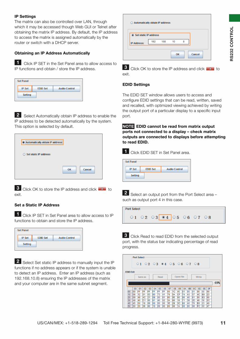
IP SettingsThe matrix can also be controlled over LAN, through which it may be accessed though Web GUI or Telnet after obtaining the matrix IP address. By default, the IP address to access the matrix is assigned automatically by the router or switch with a DHCP server.
Obtaining an IP Address Automatically
Click IP SET in the Set Panel area to allow access to IP functions and obtain / store the IP address.
Select Automatically obtain IP address to enable the IP address to be detected automatically by the system. This option is selected by default.
Click OK to store the IP address and click to exit.
Set a Static IP Address
Click IP SET in Set Panel area to allow access to IP functions to obtain and store the IP address.
Select Set static IP address to manually input the IP functions if no address appears or if the system is unable to detect an IP address. Enter an IP address (such as 192.168.10.8) ensuring the IP addresses of the matrix and your computer are in the same subnet segment.
Click OK to store the IP address and click to exit.
EDID Settings
The EDID SET window allows users to access and configure EDID settings that can be read, written, saved and recalled, with optimized viewing achieved by writing the output port of a particular display to a specific input port. NOTE EDID cannot be read from matrix output ports not connected to a display – check matrix outputs are connected to displays before attempting to read EDID.
Click EDID SET in Set Panel area.
Select an output port from the Port Select area – such as output port 4 in this case.
Click Read to read EDID from the selected output port, with the status bar indicating percentage of read progress.
RS2
32 C
ON
TRO
L
1
2
3
1
2
2
3

12 Technical support: [email protected] EMEA/ROW: +44 (0) 1793 230 343
RS232 C
ON
TRO
L
Once the reading process is complete, the output port EDID will appear in the table below.
Next, select an input port in the same Port Select area - such as input port 2 in this case - and click Write to save the current EDID to the selected input port. Wait a few seconds for the process to complete.
Once the writing process is complete, click Save as to save the EDID as a bin file.
To write previously saved output port EDID in bin format, click Open File and choose the relevant bin file before selecting an input port and click Write. It is recommended this is done often if specific output EDID from particular display devices are frequently used.
Configuring Advanced Settings
Advanced matrix settings can be configured by clicking SETTING in the Set Panel Area.
vi. Audio Processor Control
The MX-0808-4K features enhanced audio capabilities, including ARC (Audio Return Channel) and the capacity to extract optical and coaxial S/PDIF Digital Audio output from HDMI transmissions. Audio processing software is also included for the adjustment of individual source audio inputs to outputs, HDMI and ARC settings and delay to avoid audio/video synchronization issues.
4
5
6
7
1 HDMI Long Cable Mode
In instances where the distance of the cable may be effecting transmission quality, this setting toggles ON/ OFF to improve display quality and stability.. Click Unlock, enter password 123456 and follow the on-screen instructions to activate HDMI Long Cable Mode – reboot the matrix for the change to take effect.
NOTE: this setting is designed for assistance only if slight cable distance excess may be an installation factor, it is not intended to bypass cable distance lim-itations. We recommend following cable distances as stated in the Specifications section of this manual.
2 Unlock Unlocks HDMI Long Cable Mode function - enter pass-word 123456 and follow the on-screen instructions to activate HDMI Long Cable Mode – reboot the matrix for the change to take effect.
3 Factory Reset Restores the matrix to its initial Default Setting as shipped. Reboot the matrix for this setting to take effect. Warning: This action will erase all previously saved data/settings – this cannot be undone.
4 Copy EDID Setting Select I/O from dropdown to copy output ports 1~8 EDID to specific input ports 1~8
5 Copy EDID Press to copy selected Output port EDID to selected Input port.
12 3
4
5
13US/CAN/MEX: +1-518-289-1294 Toll Free Technical Support: +1-844-280-WYRE (9973)
RS2
32 C
ON
TRO
L
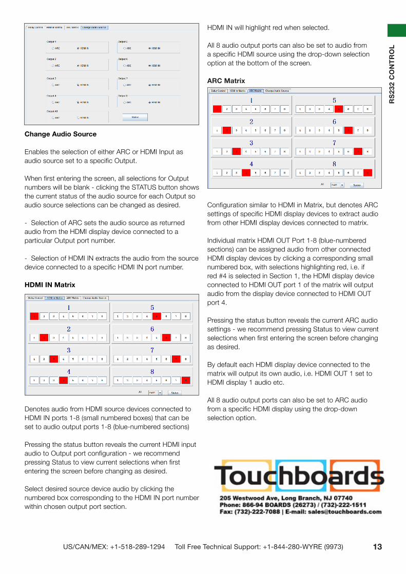
Change Audio Source Enables the selection of either ARC or HDMI Input as audio source set to a specific Output.
When first entering the screen, all selections for Output numbers will be blank - clicking the STATUS button shows the current status of the audio source for each Output so audio source selections can be changed as desired.
- Selection of ARC sets the audio source as returned audio from the HDMI display device connected to a particular Output port number.
- Selection of HDMI IN extracts the audio from the source device connected to a specific HDMI IN port number.
HDMI IN Matrix
Denotes audio from HDMI source devices connected to HDMI IN ports 1-8 (small numbered boxes) that can be set to audio output ports 1-8 (blue-numbered sections)
Pressing the status button reveals the current HDMI input audio to Output port configuration - we recommend pressing Status to view current selections when first entering the screen before changing as desired.
Select desired source device audio by clicking the numbered box corresponding to the HDMI IN port number within chosen output port section.
HDMI IN will highlight red when selected.
All 8 audio output ports can also be set to audio from a specific HDMI source using the drop-down selection option at the bottom of the screen.
ARC Matrix
Configuration similar to HDMI in Matrix, but denotes ARC settings of specific HDMI display devices to extract audio from other HDMI display devices connected to matrix.
Individual matrix HDMI OUT Port 1-8 (blue-numbered sections) can be assigned audio from other connected HDMI display devices by clicking a corresponding small numbered box, with selections highlighting red, i.e. if red #4 is selected in Section 1, the HDMI display device connected to HDMI OUT port 1 of the matrix will output audio from the display device connected to HDMI OUT port 4.
Pressing the status button reveals the current ARC audio settings - we recommend pressing Status to view current selections when first entering the screen before changing as desired.
By default each HDMI display device connected to the matrix will output its own audio, i.e. HDMI OUT 1 set to HDMI display 1 audio etc.
All 8 audio output ports can also be set to ARC audio from a specific HDMI display using the drop-down selection option.
14 Technical support: [email protected] EMEA/ROW: +44 (0) 1793 230 343
3
6
4 5
RS232 C
ON
TRO
L
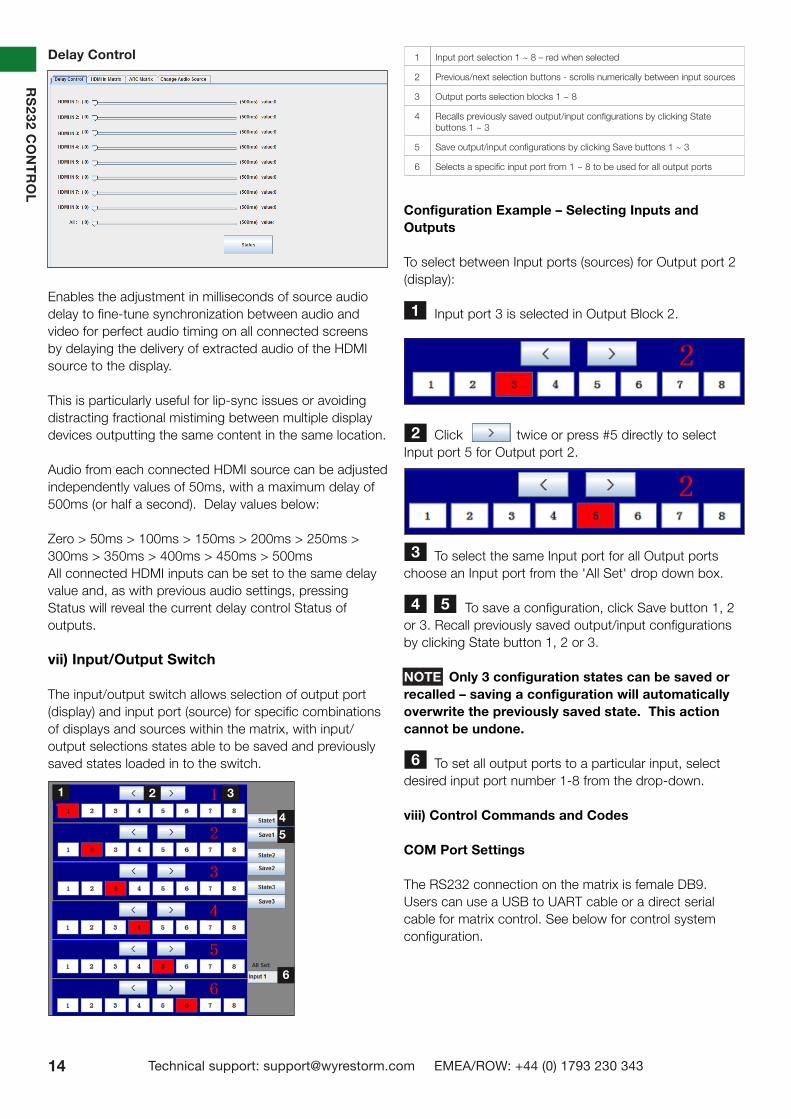
Delay Control
Enables the adjustment in milliseconds of source audio delay to fine-tune synchronization between audio and video for perfect audio timing on all connected screens by delaying the delivery of extracted audio of the HDMI source to the display.
This is particularly useful for lip-sync issues or avoiding distracting fractional mistiming between multiple display devices outputting the same content in the same location.
Audio from each connected HDMI source can be adjusted independently values of 50ms, with a maximum delay of 500ms (or half a second). Delay values below:
Zero > 50ms > 100ms > 150ms > 200ms > 250ms > 300ms > 350ms > 400ms > 450ms > 500ms All connected HDMI inputs can be set to the same delay value and, as with previous audio settings, pressing Status will reveal the current delay control Status of outputs.
vii) Input/Output Switch
The input/output switch allows selection of output port (display) and input port (source) for specific combinations of displays and sources within the matrix, with input/ output selections states able to be saved and previously saved states loaded in to the switch.
Configuration Example – Selecting Inputs and Outputs
To select between Input ports (sources) for Output port 2 (display):
Input port 3 is selected in Output Block 2.
Click twice or press #5 directly to select Input port 5 for Output port 2.
To select the same Input port for all Output ports choose an Input port from the 'All Set' drop down box.
To save a configuration, click Save button 1, 2 or 3. Recall previously saved output/input configurations by clicking State button 1, 2 or 3.
NOTE Only 3 configuration states can be saved or recalled – saving a configuration will automatically overwrite the previously saved state. This action cannot be undone.
To set all output ports to a particular input, select desired input port number 1-8 from the drop-down.
viii) Control Commands and Codes
COM Port Settings
The RS232 connection on the matrix is female DB9. Users can use a USB to UART cable or a direct serial cable for matrix control. See below for control system configuration.
1 Input port selection 1 ~ 8 – red when selected
2 Previous/next selection buttons - scrolls numerically between input sources
3 Output ports selection blocks 1 ~ 8
4 Recalls previously saved output/input configurations by clicking State buttons 1 ~ 3
5 Save output/input configurations by clicking Save buttons 1 ~ 3
6 Selects a specific input port from 1 ~ 8 to be used for all output ports
1
2
1 2 3
45
6

15US/CAN/MEX: +1-518-289-1294 Toll Free Technical Support: +1-844-280-WYRE (9973)
RS2
32 C
ON
TRO
L
Command Format
For reference - the command format to be input is:Type “cir” - followed by a “space” - then the “code number” – and hit the “Enter” key.For example, the command cir 39 + “Enter”, will tell the matrix to select the next input source for output 4.See Matrix Control Codes section below for more details on code numbering
Matrix Control Codes
Command code input in the COM Control software follows a strict format for commands to be understood by the system. Care must be taken when inputting and checking code, with codes double-checked for input accuracy if commands are not accepted or incorrectly actioned by the matrix or control system.
Configuration Example - Control Code Introduction
Using Output1 as an example to explain control code definition and application – all other control command
codes are identified in the same way.
Original Table
Description Table
If a control command is successfully sent to the device via the COM control software, the current output state selected will feedback to show the input port selected. The following table shows the return status format:
For example, if cir 51”Enter” is sent successfully to the matrix, it will feedback “s62”, meaning output 6 has selected input 2.
Read Status Command
The command length of the read status is 4 bytes. Type “bc” - followed by a “space” - and hit the “Enter” key.
13 Technical Support: [email protected] US: +866 677 0053 EU: +44 (0) 1793 230 343
AD
VA
NC
ED
RE
MO
TE C
ON
TRO
L
11. Advanced Remote Control
IR Call Back and Third Party Control systems
Please note: Due to the differing method of control based on location, if you are using a third party control system, learning the control from the IR is NOT recommended as control will be limited to scrolling up/down between inputs. For discrete source selection you will need to import discrete hex codes for control systems. These can be obtained through the Wyrestorm website, by contacting our technical support or you can input them manually.
For reference: The IR is NEC and possesses a carrier wave of 38KHz with a system code of 0x00
OUTPUTCHANNEL
INPUT SELECT
1
2
3
4
5
6
7
8
0x1d 0x0d
0x1b 0x15
0x12 0x08
0x55 0x4a
0x06 0x03
0x07 0x02
0x44 0x51
0x1e 0x1a
Output1 source select key code: 0x80 0x81 0x82 0x83 0x84 0x85 0x86 0x87
Output2 source select key code: 0x90 0x91 0x92 0x93 0x94 0x95 0x96 0x97
Output3 source select key code: 0xa0 0xa1 0xa2 0xa3 0xa4 0xa5 0xa6 0xa7
Output4 source select key code: 0xb0 0xb1 0xb2 0xb3 0xb4 0xb5 0xb6 0xb7
Output5 source select key code: 0xc0 0xc1 0xc2 0xc3 0xc4 0xc5 0xc6 0xc7
Output6 source select key code: 0xd0 0xd1 0xd2 0xd3 0xd4 0xd5 0xd6 0xd7
Output7 source select key code: 0xe0 0xe1 0xe2 0xe3 0xe4 0xe5 0xe6 0xe7
Output8 source select key code: 0xf0 0xf1 0xf2 0xf3 0xf4 0xf5 0xf6 0xf7
12. Advanced Operation
Controlling the MX0606/0808-PP using RS232 and COMCTL PC Software
Typically, unless alternative methods of controlling the matrix are chosen or problems with device communication through the matrix encountered, basic operation is all that is required to operate your MX0606/0808-PP. However, the following information on advanced operation will detail how the matrix system can be configured and for advanced control and settings can be altered or data manually input should such problems arise, as well as configuring the system for third party control.
RS232 Remote Control
Control of the matrix is possible through RS232 using third party control systems or the dedicated Wyrestorm COM CTL software included with your purchase (also downloadable from www.wyrestorm.com).
RS232 Setting
Should third party control be required, please see below for control system configuration and hex code input. The RS232 connection on the matrix is female QB9 Users can use a USB to RS232 cable or a direct male to female serial cable.
5 4 3 2 1
9
GroundRXD TXD
8 7 6
Female connector - 9 holes
1 2 3 4 5
6
GroundRXDTXD
7 8 9
Male connector - 9 holes
RXD Receive serial data from PCTXD Transmit serial data to PC
Baud rate 9600bps
Data bits 8bits
Parity None
Stop bits 1
Flow control None
Com Port Setting
COM CTL
After fully connecting all inputs and outputs to the matrix and installing the software, on opening the program the control window will display information from the matrix, such as messages received from the switch such as input/output details, firmware version and control commands/HEX codes that allow the system to be controlled remotely, as well as buttons used to navigate the screen.
17 Technical Support: [email protected] US: +866 677 0053 EU: +44 (0) 1793 230 343
AD
VA
NC
ED
OP
ER
ATIO
N
A Receives the specific IR code used to operate the Matrix via remote control. Can contain a custom or data code. Third party remote control codes are also shown.
B IR code can also be input manually in the event it is unreadable.
01 Press to automatically read the current IR code from the device.
01 The resulting code appears in the wait to modify code section where output and input code can be edited if necessary (for example if using third party control systems NOTE Modified code can be saved as a Custom code and read directly from a library of stored custom codes. All code should be different.
03 Write the code from the Modify section to the device to authorise remote control usage. NOTE All input/output boxes should contain code. If inputting manually, make sure there is no repetition of code. Modify Section - Control Commands and Code Code input in the Input/Output section and Control code section must follow a strict format for the command to be understood by the system. For reference - the command format to be input is: Type “Cir” - followed by a “space” - then the “code number” – and hit the ”enter” key. For example Cir 39 + ”enter” (equals a hex code of 63 69 72 20 33 39 0D 0A) Such a command will tell the matrix to select the next Input source for Output 4
B
0204
MX0606/0808-PP Control Code
Output 1 <”08” “09”>
1 ”00” 2 ”01” 3 ”02” 4 ”03” 5 ”04” 6 ”05” 7 ”06” 8 ”07”
Output 2 <”18” “19”>
1 ”10” 2 ”11” 3 ”12” 4 ”13” 5 ”14” 6 ”15” 7 ”16” 8 ”07”
Output 3 <”28” “29”>
1 ”20” 2 ”21” 3 ”22” 4 ”23” 5 ”24” 6 ”25” 7 ”26” 8 ”27”
Output 4 <”38” “39”>
1 ”30” 2 ”31” 3 ”32” 4 ”33” 5 ”34” 6 ”35” 7 ”36” 8 ”37”
Output 5 <”48” “49”>
1 ”40” 2 ”41” 3 ”42” 4 ”43” 5 ”44” 6 ”45” 7 ”46” 8 ”47”
Output 6 <”58” “59”>
1 ”50” 2 ”51” 3 ”52” 4 ”53” 5 ”54” 6 ”55” 7 ”56” 8 ”57”
Output 7 <”68” “69”>
1 ”60” 2 ”61” 3 ”62” 4 ”63” 5 ”64” 6 ”65” 7 ”66” 8 ”67”
Output 8 <”78” “79”>
1 ”70” 2 ”71” 3 ”72” 4 ”73” 5 ”74” 6 ”75” 7 ”76” 8 ”77”
If the control command is sent successfully, the current output state selected will feedback to show the in-put port selected. The return status format is as follows:
S X1 X2 ‘\r’ ‘\n’
This translates as:
“S” Output port Input port
1st byte 2nd byte 3rd byte
For example: if Cir 44 “enter” is sent successfully to the matrix, it will feedback “s55” – meaning Output 5 has selected Input 5.
Read Status Command
The command length of the read status is 4 bytes. Type “bc” - followed by a “space” - and hit the “enter” key.
For example: bc + “enter”
NOTE Such a command will tell the matrix to feedback the current status of all outputs. See below for status format (16 bytes)
1 2 3 4 5 6 7 8 9 10 11 12 13 14 15 16
‘\r’ ‘\n’ s X1 X2 s X3 X4 s X5 X6 s X7 X8 ‘\r’ ‘\n’
Each of the X1, X2, X3, X4, X5, X6, X7, X8 signifies the related input as chosen by a specific output: X1 = Out-put 1, X2 = Output 2 etc. For example, a status reading of “\r\ns12s22s53s45\r\n” signifies the following matrix settings.
Output 1 Output 2 Output 3 Output 4 Output 5 Output 6 Output 7 Output 8
Input 1 Intput 2 Intput 3 Intput 4 Intput 5 Intput 6 Intput 7 Intput 8
03 EDID Set
MX0808-PP
Output Port Element Description
Output 1
<“08”
< Indicates the operation of selecting the previous input source for Output 1.
08
• Indicates the control code of “<”. • Sends the command cir 08”Enter” to select the previous input source for output 1.
>“09”
> Indicates the operation of selecting the next input source for output 1.
09• Indicates the control code of “>”.• Sends the command cir 09”Enter” to select the next input source for output 1.
1“00”
1 Indicates the operation of selecting input source 1 for output 1.
00• Indicates the control code of “1”.• Sends the command cir 00”Enter” to select the input source 1 for output 1.
2“01”
2 Indicates the operation of selecting input source 2 for output 1.
01• Indicates the control code of “2”.• Sends the command cir 00”Enter” to select the input source 1 for output 1.
Other control command codes are similarly defined

16 Technical support: [email protected] EMEA/ROW: +44 (0) 1793 230 343
RS232 C
ON
TRO
L
Example:Inputting bc + “enter” will feedback the current status of all outputs, such as:"s11\r\n" ,"s22\r\n" ,"s33\r\n" ,"s44\r\n" ,"s55\r\n" ,"s66\r\n" ,"s77\r\n" ,"s88\r\n". Definition: Output 1 selects Input 1, Output 2 selects Input 2 etc.
To read the current status of all outputs using the COM debug software:
Launch the COM debug software.
Configure the COM settings.
x. LAN Control
The WyreStorm MX-0808-4K can also be controlled via LAN over a network/web browser, offering integration protocols and full compatibility with market leading control systems such as AMX, Control 4, Crestron, RTI and WyreStorm Enado.
Use a ‘straight through’ Ethernet cable for switch/router connection and a ‘cross-over’ cable for connection to a PC. Using the incorrect cable will not damage your equipment, but it may result in poor/no connection. Make sure that your LAN cable is correctly terminated and firmly connected to ports before running the software.
For LAN control functionality the IP address of the matrix needs to be obtained, which can be achieved a number of ways:
Method 1: Connect the matrix to a network via good quality Ethernet cable and use a PC to scan the local network to identify the IP address of the matrix using third party software.
Method 2: Use the software interface of the specific router or switch being used to find the matrix connected to it.
Method 3: Use SmartSet GUI, which is available to download from the WyreStorm website.
There is a simple switching interface via web page embedded in the matrix LAN board, which can be accessed by typing the obtained IP address into a web browser.
NOTE Supported browsers are Internet Explorer, Chrome, Safari and Firefox - always ensure you are running the latest version of your browser.
Your browser will direct you to a Web Log in page to access the switching interface in your internet browser.
Enter the default password of ten zeros ‘0000000000’ and click to take you to the LAN matrix controller screen.
The LAN matrix controller interface enables the selection
!
1
2
4
3
1
2
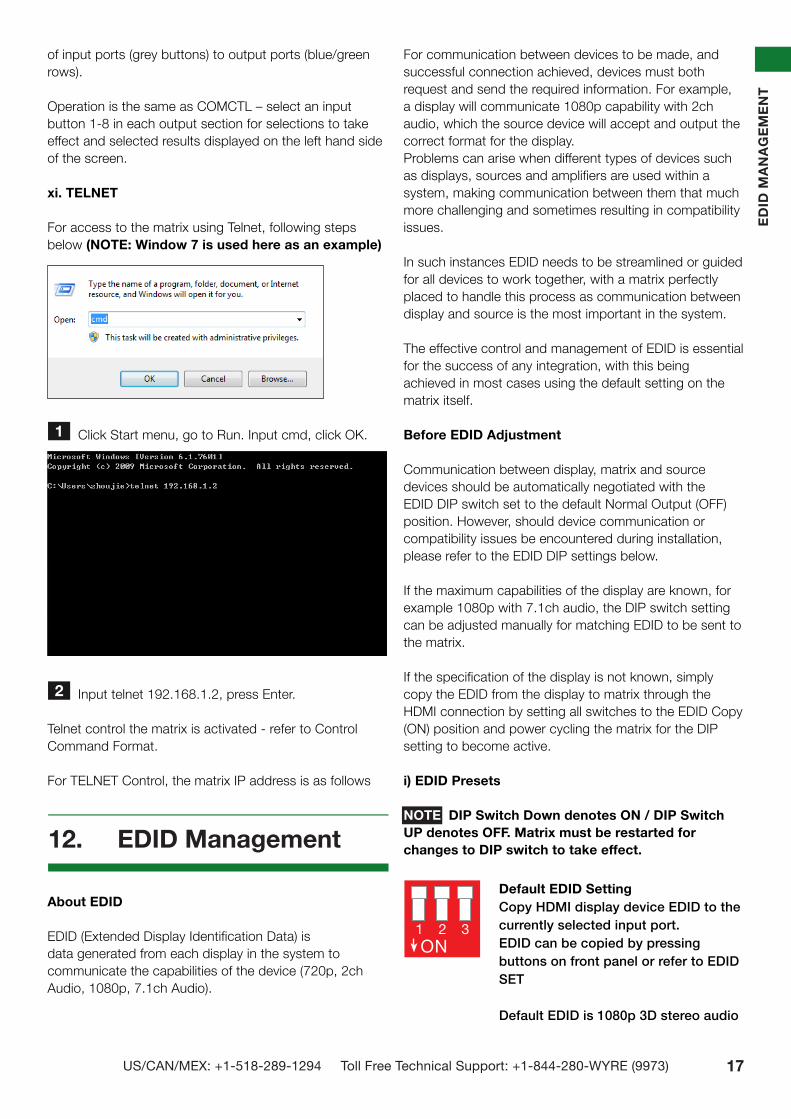
17US/CAN/MEX: +1-518-289-1294 Toll Free Technical Support: +1-844-280-WYRE (9973)
Default EDID SettingCopy HDMI display device EDID to the currently selected input port. EDID can be copied by pressing buttons on front panel or refer to EDID SET
Default EDID is 1080p 3D stereo audio
1 2 3ON
EDID
MA
NA
GEM
ENT
of input ports (grey buttons) to output ports (blue/green rows).
Operation is the same as COMCTL – select an input button 1-8 in each output section for selections to take effect and selected results displayed on the left hand side of the screen.
xi. TELNET
For access to the matrix using Telnet, following steps below (NOTE: Window 7 is used here as an example)
Click Start menu, go to Run. Input cmd, click OK.
Input telnet 192.168.1.2, press Enter.
Telnet control the matrix is activated - refer to Control Command Format.
For TELNET Control, the matrix IP address is as follows
About EDID EDID (Extended Display Identification Data) is data generated from each display in the system to communicate the capabilities of the device (720p, 2ch Audio, 1080p, 7.1ch Audio).
For communication between devices to be made, and successful connection achieved, devices must both request and send the required information. For example, a display will communicate 1080p capability with 2ch audio, which the source device will accept and output the correct format for the display. Problems can arise when different types of devices such as displays, sources and amplifiers are used within a system, making communication between them that much more challenging and sometimes resulting in compatibility issues.
In such instances EDID needs to be streamlined or guided for all devices to work together, with a matrix perfectly placed to handle this process as communication between display and source is the most important in the system.
The effective control and management of EDID is essential for the success of any integration, with this being achieved in most cases using the default setting on the matrix itself.
Before EDID Adjustment
Communication between display, matrix and source devices should be automatically negotiated with the EDID DIP switch set to the default Normal Output (OFF) position. However, should device communication or compatibility issues be encountered during installation, please refer to the EDID DIP settings below.
If the maximum capabilities of the display are known, for example 1080p with 7.1ch audio, the DIP switch setting can be adjusted manually for matching EDID to be sent to the matrix.
If the specification of the display is not known, simply copy the EDID from the display to matrix through the HDMI connection by setting all switches to the EDID Copy (ON) position and power cycling the matrix for the DIP setting to become active.
i) EDID Presets
NOTE DIP Switch Down denotes ON / DIP Switch UP denotes OFF. Matrix must be restarted for changes to DIP switch to take effect.
1
2
12. EDID Management

18 Technical support: [email protected] EMEA/ROW: +44 (0) 1793 230 343
ii) Copying Output Port EDID
Before copying output port EDID, ensure the matrix port is connected to a display - EDID copy will fail without connection to output device.
Example: To copy EDID from an HDMI display connected to matrix output port 1 to input port 2:
Set EDID DIP switch 1, 2 and 3 to the UP position to activate EDID Copy mode as per setting below.
Reboot the matrix.
Press the selection buttons on the matrix front panel
to select input port 2 on output port 1 > the number LED number indicator will blink to confirm action.
Press and hold the Enter button for approximately five seconds until the message CPY OK is displayed to confirm EDID copy is successful.NOTE To apply EDID of the other HDMI displays to all the input ports, set the EDID DIP switch to the required position and reboot the matrix for the setting to take effect.
Output port EDID can also be copied to input ports using the COM Control software. See EDID Settings for details.
Generally, the majority of HD distribution installation issues are either caused by minor connection errors, communication problems between devices, or when the transmission of high signal bandwidth is attempted using insufficient cable.
Should you encounter any technical difficulties when installing and configuring the matrix, we are confident solutions can be found by working through the following troubleshooting checklist before seeking alternative technical support. No Picture or Poor Quality Picture
1) Power – Are all sources, displays and matrix definitely powered and firmly connected? Please use matrix power supply included. 2) If possible, always use test equipment prior to installation and to troubleshoot any problems. 3) Distance – Is the cable too long for the signal to be transmitted effectively? Make sure the cable distance matches the project requirements and is well within the maximum transmission distance of the signal. See Specification section for details. NOTE If approaching the limits of the transmission capabilities, transmission should be extended by using an extender set to ensure the signal reaches its destination effectively.
4) Cable Joins – If using an extender set to lengthen transmission, joins in the cable run or RJ45 connectors
TRO
UB
LESHO
OTIN
G
4K UHD, 2.1 audio
Reserved (no function)
1 2 3ON
1 2 3ON
13. Troubleshooting
Default EDID SettingCopies HDMI display EDID to the selected input port
1
2
3
4
5
6
1 2 3ON
1080p 3D stereo audio
1080p 5.1 audio
1080p 7.1 audio
1080p stereo audio
1080i stereo audio
1 2 3ON
1 2 3ON
1 2 3ON
1 2 3ON
1 2 3ON

19US/CAN/MEX: +1-518-289-1294 Toll Free Technical Support: +1-844-280-WYRE (9973)
TRO
UB
LESH
OO
TIN
G
can impact on signal strength, resulting in reduced transmission that may manifest itself in incorrect picture quality, picture dropping out or a complete lack of picture.
5) Cable Choice and Signal Reduction – Ensure good quality high speed HDMI 1.4v cables are used, with care taken to avoid bending, twisting, snagging or any other form of obstruction to the cable that may interfere with successful transmission of an HDMI signal - we recommend using WyreStorm Express HDMI cables.
If using an extender set to lengthen transmission between matrix and display, please note that the use of stranded patch leads as interconnects between patch panels or wall outlets or the use of CCA (Copper Clad aluminium) cables can reduce transmission rates by up to 40%. We recommend solid core straight through with minimum connections used wherever possible. 6) Correct connection – It may seem obvious but double check all cables are fully inserted and connected to the correct ports. NOTE Even a fraction off can be the difference between a perfect picture and a blank screen. Double check all connections are firmly made in the correct ports.
7) Cable wired to 568B standard? If using an UTP extender to lengthen transmission from the matrix, check the cable wired and terminated correctly and are those terminations connected to the correct ports? Incorrect wiring and termination will result in unstable operation or a blank screen. 8) Electrical interference – Could any form of electrical or environmental interference be generated that may be effecting signal transmission? If so, attempt to remove the source of interference or move the cable run to decrease the effects of the interference.
9) Is a picture achieved when connecting the source directly to the display? If not then the problem could lie with the input or output device rather than the means of distribution.
10) HDMI lead condition and quality – HDMI cables and connectors are delicate and can be damaged much easier than component or coax cable. Furthermore, lead quality varies dramatically, particularly in lower price brackets. Swap HDMI leads and check operation – damage to or quality of your leads could be the problem. If in doubt, swap them over. Always take care inserting
and extracting your HDMI from matrix ports so as not to damage the connectors or ports.
11) Picture speckles/HD ‘noise’ – represents a poorly established signal that may be caused by poor quality or excessive HDMI cable lengths. Try swapping the display adaptors from a location that is functioning properly or swapping the outputs of the matrix switch used.
If the problem remains on the same screen this may be caused by a connection problem between matrix and display – turn off all equipment and swap the signal carrying cables at both ends to ascertain if the cable or termination is at fault.
HD Noise (NO image) may be an HDCP Issue between the source and display but poor cabling can also cause this due to poor communication.
12) Blu-ray: 3D – is the equipment used 3D enabled/compatible? Is a 3D disc being played in a 3D enabled Blu-ray player or through a compatible AV receiver?
13) 4K - Are you trying to pass a 4K signal? Ensure connected devices are 4K enabled, correctly configured and outputting compatible transmissions.
4K resolution - ensure all connected devices are compatible with the UHD or DCI resolutions being transmitted. See Specification section for more details
1080p - 1920x1080p, 60Hz (if problems are experienced at 60Hz, try lowering to 50Hz)
Combined 4K / HD distributions - a WyreStorm EXP-CON-4K-DD scaler may be required between receiver and display to scale down 4K transmissions to 1080p 24fps for HD screens and upscale 1080p to 4K 30Hz for UHD displays.
14) Colour distortion – a pink or green screen indicates an incompatibility between colour spacing formats – the commonly used RGB or YUV used by older displays. Some sources allow switching between RGB and YUV which may solve any colour problems. If not, try changing the HDMI cable between the source and the matrix to rule out defective cabling. No Sound or Poor Quality Audio
Audio is transmitted within the video signal – there is no separate audio track – so generally a problem with sound will be accompanied by a problem with picture. However,

20 Technical support: [email protected] EMEA/ROW: +44 (0) 1793 230 343
FAQ
if technical issues with audio are experienced, the cause is typically communication between sources, displays and/or AV receiver settings.
1) Have specific speaker sets or zones been enabled? Some AV receivers allow individual speaker selections assigned to specific zones in the set up so check the speakers used are fully connected to the amplifier and correctly assigned within the system set up. It may be an EDID issue in that the source reads the audio EDID from the display and only requests two channel audio.
Use of MX-0808-4K EDID management to manually copy EDID from the AVR may be required.
See EDID section of this manual or contact tech support for assistance if required.
NOTE If problems are experienced when an AV receiver is used, the cause is usually the settings of the AVR itself.Refer to the AVR manufacturer’s guidelines on the correct settings to use for your requirements.
2) Consistency of audio output between devices – Is there any discrepancy between the audio output of the source, the audio or zonal settings of the AV receiver and the speaker configuration used needed for successful audio replication? If outputting 7.1, make sure all devices connected are also outputting 7.1
NOTE Occasionally with some sources, the device settings allow the specification of audio output through a TV or an HDMI port. If using an AV receiver, check the HDMI output option is selected.
3) Do all the local sources work through the AV receiver?Check the operation of each source individually.
Bandwidth
1) If using a graphics-based source (such as a PC/Mac/ media server), make sure the source resolution is set to a maximum of 4096x2160p 30Hz. Higher resolutions available for graphics-based systems require higher bandwidth that may affect transmission of signals as well as incompatibility with devices.
IR
1) Check the IR receiver windows on source, display and matrix (or the IR EXT receiver, if used) is unobstructed and
able to receive a signal from the remote handset used to control.
NOTE Locate the infrared sensor by using a flashlight to find the sensor within the device facia.
2) Is the remote handset powered and sending a signal? IR is invisible to the naked eye, so use a digital camera/ phone camera to check the remote signal – point the camera at the remote control when pressing a button.The remote transmitter can be seen flashing to indicate a signal being sent. Replace batteries if flashing is not seen on the digital camera screen.
3) Cable Issues – check or replace cables at source, matrix and display ends transmitter and receiver ends to see if control is established.
4) Are WyreStorm products being used? The use of third party products may not be compatible. Always use WyreStorm components included with your purchase or check compatibility of third party control systems with your WyreStorm dealer.
5) IR dropout - can also be due to exterior influences emitting infrared radiation that can interrupt IR signals. Ensure IR receiving windows are away from the following causes of IR interference.• Direct sunlight, Fluorescent lighting (on cold start up)• Halogen lighting• Plasma screens
Are WyreStorm products compatible with HDMI 1.4?HDMI 1.4 refers to a list of ‘features’ that a device is capable of supporting, including Ethernet channel, return audio channel, 3D etc. Due to the continuously evolving nature of the technology, HDMI Licensing LLC have now decided to simplify terminology by testing and referring to cable in terms of STANDARD or HIGH-SPEED rather than in generations 1.3, 1.4 etc.
• STANDARD (or “category 1”) HDMI cables perform at speeds of 75Mhz or up to 6.75Gbps, which is the equivalent to a 720p/1080i signal – These HDMI cables are NOT recommended.
• All WyreStorm equipment supports HIGH-SPEED (or “category 2”) HDMI cables that have been tested to perform at speeds of 340Mhz or up to 10.2Gbps.
14. FAQ

21US/CAN/MEX: +1-518-289-1294 Toll Free Technical Support: +1-844-280-WYRE (9973)
MA
INTE
NA
NC
E A
ND
PR
OVI
DED
SER
VIC
E
This is the highest bandwidth currently utilized over an HDMI cable and can successfully handle 1080p signals including those at increased color depths and/ or increased refresh rates from the source and 4K resolutions at 30Hz, 4:4:4 color.
High-Speed cables are also able to accommodate higher resolution displays, such as WQXGA cinema monitors (resolution of 2560 x 1600).
We recommend WyreStorm Express high-speed HDMI cables.
What about screens with different resolution capabilities?When sending a signal point to point a TV will communicate it’s capabilities to the source, then the source will output a suitable signal that compatible (i.e. 1080p Stereo audio).
When sending distributing a signal point to point or through a matrix, care should be taken to ensure compatibility between the source device and connected displays. A central element of the EDID 'handshake' between devices is the display communicating its resolution/audio capabilities back to the source, which will then output a suitable signal if compatible.
Problems can arise if sources and displays of varying resolution capacities are connected, such as 4K and HD sources, connecting through the matrix to 4K and 1080p screens. This can either result failed transmission delivery to screens or in reduced resolutions across all displays, regardless of the source selected as sources will output the most compatible signal that can be supported by all screens.
Check settings of sources and displays for compatibility - if combining 4K and HD sources and displays within one system, use a WyreStorm EXP-CON-4K-DD scaling device between matrix and display to up/downscale signals as required.
How does the device handle with HDCP?HDCP (High Definition Copyright Protection) is a feature built in to HDMI devices to prevent theft of or illegal distribution of HD content.
Unlike competing products, WyreStorm products are legal and comply with HDCP regulations.
They do this by assigning a “key” to every display connected to the device. HDCP “keys” are assigned to a display when connected to a HDMI device normally. This
doesn’t change when connected through a switcher or splitter; it just assigns more of them.
I can get 1080p but not 4K at a TV locationFirstly ensure that both the source is capable of outputting 4K and that the TV is a UHD screen. If this is the case then the matrix may require EDID management setting using DIP switches (See EDID section of this manual).
This useful feature provides a successful “send and receive” to ensure swift and stable EDID negotiation between the source and display.
See Troubleshooting section for more tips on problem solving.
I cannot get a signal from my A/V receiver when using a Cat 5e extender set Check to ensure that the A/V Receiver isn’t adding CEC (HDMI Control Protocol) to the outgoing signal, this can sometimes have an effect on the HDMI signal.
Clean this unit with a soft, dry cloth only. Never use alcohol, paint thinner or other harsh chemicals.
1. Damage requiring service: This unit should be serviced by a qualified service personnel if:• The DC power supply or AC adaptor has been damaged.• Objects or liquid have gotten into the unit.• The unit has been exposed to rain.• The unit does not operate normally or exhibits a marked change in performance.• The unit has been dropped or the cabinet damaged.
2. Servicing Personnel: Do not attempt to service the unit beyond that described in these operating instructions. Refer all other servicing to authorised servicing personnel.
3. Replacement Parts: When parts need replacing, ensure parts approved by the manufacturer are used – either those specified by the manufacturer or parts possessing the same characteristics as the original parts. Be aware – unauthorised substitutes may result in fire, electric shock, or other hazards and will invalidate your warranty.
15. Maintenance
16. Provided Service

22 Technical support: [email protected] EMEA/ROW: +44 (0) 1793 230 343
MA
IL-IN-SER
VICE, W
AR
RA
NTY A
ND
WA
RR
AN
TY LIMITS &
EXCLU
SION
S
4. Safety Check: After repairs or service, ask the service personnel to perform safety checks to confirm the unit is in proper working condition.
When shipping the unit, carefully pack and send it prepaid, with adequate insurance and preferably in the original packaging.
Please include a document or letter detailing the reason for return and include a daytime telephone number and/or email address where you can be contacted.
If repair is required during the limited warranty period, the purchaser will be required to provide a sales receipt or other proof of purchase, indicating date and location of purchase as well as the price paid for the product. The customer will be charged for the repair of any unit received unless such information is provided.
Should you feel your product does not function adequately due to defects in materials or workmanship, we (referred to as “the warrantor”) will, for the length of the period indicated below (starting from the original date of purchase) either:
a) Repair the product with new or refurbished parts.orb) Replace it with a new or refurbished product.
Limited warranty period:This WyreStorm product is covered by a 2 year PARTS and LABOUR warranty. During this period there will be no charge for unit repair, replacement of unit components or replacement of product if necessary.
The decision to repair or replace will be made by the warrantor. The purchaser must mail-in the product during the warranty period. This limited warranty only covers the product purchased as new and is extended to the original purchaser only. It is non-transferable to subsequent owners, even during the warranty period.A purchase receipt or other proof of original purchase date is required for the limited warranty service.
1. This Limited Warranty ONLY COVERS failures due to defects in materials or workmanship and DOES NOT COVER normal wear and tear or cosmetic damage.
The limited warranty also DOES NOT COVER damage that occurs in shipment or failures caused by products not supplied by the warrantor, failures resulting from accident, misuse, abuse, neglect, mishandling, misapplication, alteration, incorrect installation, set-up adjustment, implementation of/to consumer controls, improper maintenance, power line surge, lightening damage, modification, service by anyone other thana manufacturer-approved service centre or factory-authorised personnel, or damage attributable to acts of God.2. There are no express warranties except as listed under “limited warranty coverage.” The warrantor is not liable for incidental or consequential damage resulting from the use of this product or arising out of any breach of this warranty.
For example: damages for lost time, the cost of having a person/persons remove or re-install previously installed equipment, travel to and from service location, loss of or damage to media, images, data or other recorded/stored content. The items listed here are not exclusive, but are for illustration only.
Parts and service not covered by this limited warranty are not the responsibility of the warrantor and should be considered the responsibility of the individual.
17. Mail-in-service
18i. Warranty
18ii. Warranty Limits & Exclusions

23US/CAN/MEX: +1-518-289-1294 Toll Free Technical Support: +1-844-280-WYRE (9973)
GLO
SSA
RY
AN
D D
ISC
LAIM
ER
WYRESTORM PUBLICATION DISCLAIMER
The material contained in this document consists of information that is the sole property of WyreStorm. This document is intended to provide information to allow interfacing to the relevant WyreStorm equipment by third party products.
WYRESTORM IS NOT RESPONSIBLE FOR MALFUNCTIONS AND/OR THE IN-OPERABILITY WHICH MAY BE CAUSED BY THE APPLICATION OF THIS INFORMATION, WHETHER EXPECTED OR NOT. WyreStorm reserves the right to change software, control codes and specifications without notice.
WyreStorm will not be liable for any use of this information or any changes it may make to those products. The use of this information constitutes an agreement by the user to these limitations and exclusions.
19. Glossary
Acronym Complete Term
AC Alternating Current
COM Communication Port
DHCP Dynamic Host Configuration Protocol
DIP Dual In-line Package
DTS Digital Theater Systems
DVD Digital Versatile Disc
EDID Extended Display Identification Data
GUI Graphical User Interface
HD High Definition
HDCP High-bandwidth Digital Content Protection
HDMI High Definition Multimedia Interface
IR Infrared
LAN Local Area Network
LED Light Emitting Diode
LPCM Linear Pulse-code Modulation
PC Personal Computer
PCM Pulse-code Modulation
TV Television
UART Universal Asynchronous Receiver/Transmitter
20. Disclaimer

24 Technical support: [email protected] EMEA/ROW: +44 (0) 1793 230 343
INSTA
LLATION
REFER
ENC
E LOG
21. Installation Reference Log
INPUT
Input Number
on MatrixSource Location Source Details Source resolution/audio settings Cable
Number
1
2
3
4
5
6
7
8
OUTPUT
Output Number
on MatrixDisplay Location Display Details Source resolution/audio settings Cable
Number
1
2
3
4
5
6
7
8

25US/CAN/MEX: +1-518-289-1294 Toll Free Technical Support: +1-844-280-WYRE (9973)
GLO
SSA
RY
22. Installation Notes

26 Technical support: [email protected] EMEA/ROW: +44 (0) 1793 230 343
wyrestorm.com
WyreStorm Offices
North America Office: 23 Wood Road, Round Lake, NY 12151
Tel: +1 518-289-1293
EMEA Office: Unit 22, Ergo Business Park, Swindon, Wiltshire, SN3 3JW, UK
Tel: +44 (0) 1793 230 343
WyreStorm Technical Support
US: +1 844-280-WYRE (9973)
UK:- +44 (0) 1793 230 343
Email: [email protected]
WyreStorm Technologies reserve the right to change physical appearance or technical specification of this product at any time.
Visit wyrestorm.com for the latest information on products..
0615