Embed Size (px)
Citation preview

Model MW200 & MW600 Operating Manual
Mail Address: 226A Commerce St. Tel: 303- 465-3063 Broomfield, CO 80020 Fax: 303-465-9294
P/N 9691 REV F, 03/08/2013
OPERATING MANUAL
MODEL MW200 MODEL MW600
AIR DRYER

Model MW200 & MW600 Operating Manual
2 P/N 9691 REV F, 03/08/2013
TABLE OF CONTENTS 1.0 GENERAL ................................................................................................................3 2.0 SPECIFICATIONS ...................................................................................................3 3.0 INSTALLATION AND START-UP PROCEDURES ..................................................4 4.0 PRINCIPLES OF OPERATION................................................................................4 5.0 COMPONENT DESCRIPTION.................................................................................5 Figure 1 - Air Flow Diagram ................................................................................................5
5.1 CABINET ..............................................................................................................5 5.2 AIR COMPRESSOR.............................................................................................5 5.3 VENTILATING FAN ..............................................................................................6 5.4 FILTERS...............................................................................................................6 5.5 HEATLESS AIR DRYER & CAPACITY CONTROL VALVE .................................6 5.6 PRESSURE SWITCH & UNLOADER...................................................................6 5.7 OUTLET PRESSURE REGULATOR and GAUGE...............................................6 5.8 LOW OUTLET PRESSURE ALARM (BASIC UNIT ONLY) .................................7 5.9 ELECTRICAL SYSTEM........................................................................................7
6.0 MAINTENANCE .......................................................................................................7 6.1 SIX MONTH MAINTENANCE AND INSPECTION ...............................................7 6.2 ANNUAL MAINTENANCE AND INSPECTION.....................................................7 6.3 AIR COMPRESSOR CUP SEAL REPLACEMENT ..............................................7 6.4 REPLACEMENT OF THE INTAKE MUFFLER FILTER ELEMENT......................7
Figure 2 – Wiring Diagram for Standard Unit ......................................................................8 Figure 3 – Wiring Diagram with "H" Option .........................................................................9 Figure 4 – Wiring Diagram for "D" Option .........................................................................10 Figure 5 - Parts Index........................................................................................................11 Figure 5 - Parts Index (cont’d)..........................................................................................12 7.0 MODEL NUMBER CODING...................................................................................13 8.0 OPTIONAL EQUIPMENT.......................................................................................13
8.1 9502 HUMIDITY PROTECTION PACKAGE.......................................................13 8.2 9502-LP LOW PRESSURE HUMIDITY PROTECTION PACKAGE ...................15 8.3 9540 LOW/LOW PRESSURE REGULATOR......................................................15 8.4 9521 DISCREET ALARM BOARD......................................................................15 8.5 9533 LOW PRESSURE RELIEF VALVE............................................................15 8.6 9547 LOW-LOW PRESURE ALARM FOR BASIC UNIT ....................................15 8.7 9545 HOUR METER...........................................................................................15
Model MW200 & MW600 Operating Manual
3 P/N 9691 REV F, 03/08/2013
1.0 GENERAL 1.1 This manual covers the specifications, installation, start-up, operation, component
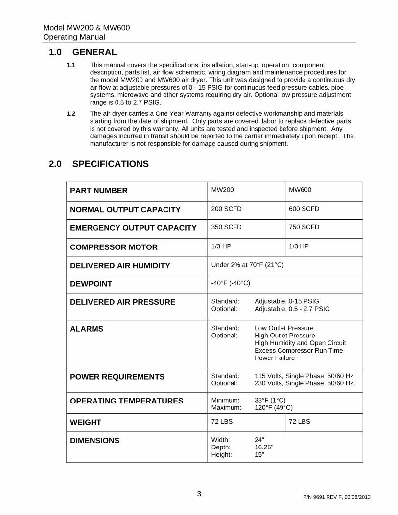
description, parts list, air flow schematic, wiring diagram and maintenance procedures for the model MW200 and MW600 air dryer. This unit was designed to provide a continuous dry air flow at adjustable pressures of 0 - 15 PSIG for continuous feed pressure cables, pipe systems, microwave and other systems requiring dry air. Optional low pressure adjustment range is 0.5 to 2.7 PSIG.
1.2 The air dryer carries a One Year Warranty against defective workmanship and materials starting from the date of shipment. Only parts are covered, labor to replace defective parts is not covered by this warranty. All units are tested and inspected before shipment. Any damages incurred in transit should be reported to the carrier immediately upon receipt. The manufacturer is not responsible for damage caused during shipment.
2.0 SPECIFICATIONS
PART NUMBER MW200
MW600
NORMAL OUTPUT CAPACITY 200 SCFD 600 SCFD
EMERGENCY OUTPUT CAPACITY 350 SCFD
750 SCFD
COMPRESSOR MOTOR 1/3 HP 1/3 HP
DELIVERED AIR HUMIDITY Under 2% at 70°F (21°C)
DEWPOINT -40°F (-40°C)
DELIVERED AIR PRESSURE Standard: Adjustable, 0-15 PSIG Optional: Adjustable, 0.5 - 2.7 PSIG
ALARMS Standard: Low Outlet Pressure Optional: High Outlet Pressure High Humidity and Open Circuit Excess Compressor Run Time Power Failure
POWER REQUIREMENTS Standard: 115 Volts, Single Phase, 50/60 Hz Optional: 230 Volts, Single Phase, 50/60 Hz.
OPERATING TEMPERATURES Minimum: 33°F (1°C) Maximum: 120°F (49°C)
WEIGHT 72 LBS 72 LBS
DIMENSIONS Width: 24" Depth: 16.25" Height: 15"

Model MW200 & MW600 Operating Manual
4 P/N 9691 REV F, 03/08/2013
3.0 INSTALLATION AND START-UP PROCEDURES 3.1 Use the handles on the air dryer to lift and move it. Rubber feet are provided for floor
mounting. The unit should be located in a well ventilated area which will allow for suitable air circulation through the cabinet.
3.2 The air dryer is designed to operate from a 115 volt, single phase, 60 Hertz power supply (alternative power options are also available). Connect the power cord supplied with the unit to a suitable power supply with a 15 Amp fuse. (If unit is 230 VAC, you will need to supply plug to power cord)
3.3 Remove the plastic plug from the low pressure outlet and the drain outlet located on the lower left side of the unit. Connect the air outlet to the application using 1/4" OD tubing and the 1/4 NPT x 1/4" push-in elbow supplied. There is a second 1/4 NPT X 3/8" push-in elbow supplied which can be used in the drain outlet to drain away condensed moisture discharge.
3.4 Move the On/Off Circuit breaker switch to the "ON" Position. When power is supplied to the unit, the system will build pressure and should begin to supply dry air to the air outlet port.
3.5 The outlet pressure can be adjusted using the outlet pressure regulator located on the front door. Pull the knob on the regulator straight out to un-lock it. Turn the knob counterclockwise to decrease and clockwise to increase the outlet air pressure. Push in on the knob to lock it..
3.6 The moisture indicator on the front door will give an color-change indication of the humidity level in the outlet air. (blue is dry air, pink is moist air).
3.7 Once installation is complete and the start-up procedure has been performed, test for leaks at all external air connections. Operate the unit for 24 hours and repeat the start-up procedure.
4.0 PRINCIPLES OF OPERATION 4.1 An air flow diagram of the air dryer is shown in figure 1. The basic system supplying the dry
outlet air includes an air compressor, a precooler, a heatless air dryer, air storage tank and outlet regulator.
4.2 Ambient air is drawn in through the intake filter into the air compressor where it is compressed to 68 PSIG. The hot, moist air then flows first through a pulsation eliminator and second into the aftercooler, to reduce the air temperature and then into the pre-filter where liquid moisture is removed and discharged to the drain outlet.
4.3 The liquid-free air then enters the desiccant air dryer where most of the remaining water in vapor form is removed. The dry air flows into the air storage tank that is monitored by the pressure switch which turns on and off the air compressor to maintain pressure between 20 and 40 PSIG in the tank. Air moves from the tank to the outlet pressure regulator and to the air outlet located on the left side of the cabinet.

Model MW200 & MW600 Operating Manual
5 P/N 9691 REV F, 03/08/2013
5.0 COMPONENT DESCRIPTION
Figure 1 - Air Flow Diagram
5.1 CABINET
5.1.1 The cabinet of the air dryer is ventilated to pull air in over the aftercooler and air compressor and out the side of the cabinet.
5.1.2 The cabinet cover can be removed for servicing the unit by removing the 8-32 machine screws.
5.2 AIR COMPRESSOR
5.2.1 The air compressor is a single cylinder, single stage, rocking piston type. The motor is equipped with built-in thermal overload protection. If the overload shuts down the compressor due to a thermal overload, the motor will automatically reset after cooling down.
5.2.2 An air intake filter assembly is mounted in the inlet of the cylinder head. The filter assembly has a replaceable filter element which should be replaced at least every six months. See section 6.
5.2.3 A safety relief valve is installed in the air compressor head to prevent the pressure in the compressor from building to more than 125 PSIG.
5.2.4 The air compressor is mounted to a vibration plate which isolates the vibration of the compressor from the cabinet and allows for easy removal of the compressor for service.
AIR COMPRESSOR
PULSATIONELIMINATOR
0.01
MIC
RON
CO
ALE
SCIN
G F
ILTE
RW
ITH P
ULSE
DRA
IN
OUTLETPRESSURE
REGULATOR
DRAIN OUTLET
PRESSURESWITCH
AIR STORAGE TANK
MOISTUREINDICATOR
AIROUTLET
CIRCUITBOARD
PRESSURESENSOR
OUTLET PRESSURERELIEF VALVE
VENTS TO CABINET
CAPACITYCONTROL
VALVE & GAUGE
OUTLETPRESSUREGAUGE
SYSTEMPRESSUREGAUGE
BYPASS RESTRICTOR
ORIFICE
MANIFOLD BLOCK
SAFETYRELIEFVALVE
AFTER-FILTER
LOW FLOWBLEED VALVE
ASSY
FAN-COOLEDAFTERCOOLER
HEATLESS DESICCANTAIR DRYER
HU
MID
ITY
BYPA
SS
SOLE
NO
ID V
ALV
E
HUM
IDITY
SE
NSO
R /
HOUS
ING
UNLOADERSOLENOIDVALVE

Model MW200 & MW600 Operating Manual
6 P/N 9691 REV F, 03/08/2013
5.3 VENTILATING FAN
5.3.1 The ventilating fan is mounted on right side of the cabinet directly above the air compressor head. Air is drawn through the side of the cabinet up over the air compressor and after cooler and exhausted out the left side of the cabinet. Remove the cover panel for access to the ventilating fan.
5.3.2 The fan thermostat operates the fan whenever the temperature inside the cabinet exceeds 100°F, and shuts off when the temperature drops below 82°F.
5.4 FILTERS
5.4.1 The pre-filter, located before the desiccant dryer, removes the liquid moisture condensed by the cooling of the air in the after cooler and discharge the moisture out the drain outlet.
5.4.2 The after-filter, located before the dry air outlet port, removes any particulates created by the operation of the desiccant dryer.
5.5 HEATLESS AIR DRYER & CAPACITY CONTROL VALVE
5.5.1 The heatless air dryer removes virtually all moisture from the supply air through the use of desiccant and pressurization. The capacity control valve is used to maintain a constant back pressure of 68 psig in the heatless air dryer. It also prevents more than the maximum emergency flow rate from flowing through the outlets and serves as a check valve to prevent dry air from the air storage tank from flowing back through the heatless dryer when the compressor shuts down.
5.5.2 The pressure in the heatless air dryer is critical to the drying process. It must be maintained at 68 PSIG (+/- 2 PSIG) as read on the capacity control valve gauge whenever the air compressor is operating. To adjust the capacity control valve, allow the system pressure to drop to 20 PSIG and the air compressor to start. Pull the lock-ring out away from the valve body and turn the adjustment knob either clockwise to raise the pressure or counterclockwise to lower the pressure. Once the adjustment has been made, push the lock-ring back towards the valve body.
5.6 PRESSURE SWITCH & UNLOADER
5.6.1 The pressure switch maintains the system pressure in the air storage tank by turning on the air compressor and desiccant dryer when the system pressure falls below 20 psig and turns them off when the system pressure reaches 40 psig.
5.6.2 The unloader solenoid valve, located at the heatless dryer inlet port, dumps any pressure in the compressor lines whenever the compressor turns off. This eliminates the air compressor from having to start up against any pressure.
5.7 OUTLET PRESSURE REGULATOR and GAUGE
5.7.1 The outlet pressure regulator and outlet pressure gauge are mounted on the front panel. The regulator reduces the pressure of the air to the desired outlet pressure. Pull the knob straight out to un-lock and then turn the knob counterclockwise to decrease and clockwise to increase the outlet air pressure. Push the knob in to lock the setting.
5.8 LOW FLOW BLEED VALVE
5.8.1 The low flow bleed valve is designed to bleed a small amount of dry air, putting a minimum load on the system. The valve should be opened only if there is an extremely small amount of usage at the application, or if the output of the system is dead-headed.
Model MW200 & MW600 Operating Manual
7 P/N 9691 REV F, 03/08/2013
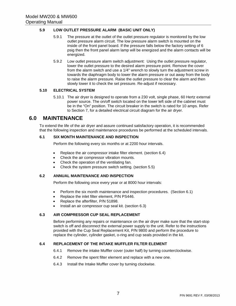
5.9 LOW OUTLET PRESSURE ALARM (BASIC UNIT ONLY)
5.9.1 The pressure at the outlet of the outlet pressure regulator is monitored by the low outlet pressure alarm circuit. The low pressure alarm switch is mounted on the inside of the front panel board. If the pressure falls below the factory setting of 6 psig then the front panel alarm lamp will be energized and the alarm contacts will be energized.
5.9.2 Low outlet pressure alarm switch adjustment: Using the outlet pressure regulator, lower the outlet pressure to the desired alarm pressure point. Remove the cover from the alarm switch and use a 1/4" wrench to slowly turn the adjustment screw in towards the diaphragm body to lower the alarm pressure or out away from the body to raise the alarm pressure. Raise the outlet pressure to clear the alarm and then slowly lower it to check the set pressure. Re-adjust if necessary.
5.10 ELECTRICAL SYSTEM
5.10.1 The air dryer is designed to operate from a 230 volt, single phase, 60 Hertz external power source. The on/off switch located on the lower left side of the cabinet must be in the “On” position. The circuit breaker in the switch is rated for 10 amps. Refer to Section 7, for a detailed electrical circuit diagram for the air dryer.
6.0 MAINTENANCE To extend the life of the air dryer and assure continued satisfactory operation, it is recommended that the following inspection and maintenance procedures be performed at the scheduled intervals.
6.1 SIX MONTH MAINTENANCE AND INSPECTION
Perform the following every six months or at 2200 hour intervals.
Replace the air compressor intake filter element. (section 6.4) Check the air compressor vibration mounts. Check the operation of the ventilating fan. Check the system pressure switch setting. (section 5.5)
6.2 ANNUAL MAINTENANCE AND INSPECTION
Perform the following once every year or at 8000 hour intervals:
Perform the six month maintenance and inspection procedures. (Section 6.1) Replace the inlet filter element, P/N PS446. Replace the afterfilter, P/N 51898. Install an air compressor cup seal kit. (section 6.3)
6.3 AIR COMPRESSOR CUP SEAL REPLACEMENT
Before performing any repairs or maintenance on the air dryer make sure that the start-stop switch is off and disconnect the external power supply to the unit. Refer to the instructions provided with the Cup Seal Replacement Kit, P/N 9800 and perform the procedure to replace the cylinder, cylinder gasket, o-ring and cup seals provided in the kit.
6.4 REPLACEMENT OF THE INTAKE MUFFLER FILTER ELEMENT
6.4.1 Remove the intake Muffler cover (outer half) by turning counterclockwise.
6.4.2 Remove the spent filter element and replace with a new one.
6.4.3 Install the Intake Muffler cover by turning clockwise.

Model MW200 & MW600 Operating Manual
8 P/N 9691 REV F, 03/08/2013
Figure 2 – Wiring Diagram for Standard Unit
8
7
INC
OM
ING
PO
WE
R Gn
STA
RT-
STO
PS
WIT
CH
L1 T1
T2L2
79
238
1022
FAN
MO
TOR
AM
BE
RP
OW
ER
-ON
LIG
HT
L1L2
13
T1
A1
T2
PO
WE
R C
ON
TAC
TOR
A2
14
56
AIR
CO
MP
RE
SS
OR
Gn
43
Gn
WIR
ING
DIA
GR
AM
MW
200
MW
600
STA
ND
AR
D U
NIT
WB
k
HE
ATLE
SS
DR
YE
RTI
ME
R
HE
ATLE
SS
DR
YE
R4-
WAY
VA
LVEUN
LOA
DE
R V
ALV
E7
23
22FA
NTH
ER
MO
STA
T
63
1516
45
211
2
9
10
L1L2
G
2
453 1
RE
DA
LAR
MLI
GH
T
18
19
1211
SY
ST
EM
PR
ES
SU
RE
SW
ITC
H
L1
L2
T1
T2
1211 13
14
NO
NC
SU
MM
AR
YA
LAR
MP
LUG
21
20
10 17
20
21
LOW
OU
TLE
T
ALA
RM
PR
ES
SU
RE
SW
ITC
H(C
LOS
ED
ON
ALA
RM
)
LOW
OU
TLE
TP
RE
SS
UR
EA
LAR
M R
ELA
Y
24
24
25
25
HO
UR
ME
TER
Model MW200 & MW600 Operating Manual
9 P/N 9691 REV F, 03/08/2013
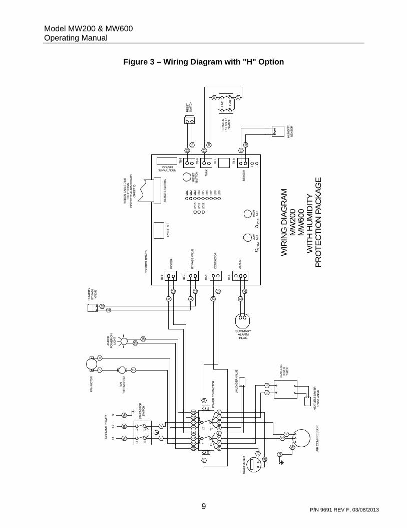
Figure 3 – Wiring Diagram with "H" Option
8
SUMMARYALARMPLUG
BY-
PAS
S V
ALV
E
PO
WE
R
CO
NTA
CTO
R
ALA
RM
7
INC
OM
ING
PO
WE
R Gn
STA
RT-
STO
PS
WIT
CH
L1 T1
T2L2
79
258
1026
FAN
MO
TOR
AM
BE
RP
OW
ER
-ON
LIG
HT
HU
MID
ITY
BY-
PAS
SVA
LVE
11
12
TB
-1
TB
-2
L1L2
13
T1
C1
T2
PO
WE
R C
ON
TAC
TOR
C2
14
56
AIR
CO
MP
RE
SS
OR
Gn
43
Gn
TB
-3
TB
-4
SY
ST
EM
PR
ES
SU
RE
SW
ITC
H
TB
-6
TB
-5
CO
NT
RO
L B
OA
RD
CY
CLE
KIT
RE
SE
TB
UT
TON
FRONT PANELDISPLAY
LD1
LD1
LD11
LD10
LD3
LD2
LD4
LD3
LD2
TB
-8
TB
-7
HIG
HS
ET
LOW
SE
TLD
14LD
13
TAN
K
SE
NS
OR
LD12
LD5
LD6
LD8
LD7
LD9
20
19
18
17
LIN
E
LOA
D
17
18
HU
MID
ITY
SE
NS
OR
WB
k
HE
ATLE
SS
DR
YE
RT
IME
R
16
15R
ES
ET
SW
ITC
H
UN
LOA
DE
R V
ALV
E725
26
FAN
TH
ER
MO
STA
T
RE
MO
TE A
LAR
MS
RIB
BO
N C
AB
LE 7
449
TO O
PTI
ON
AL
DIS
CR
ET
E A
LAR
M B
OA
RD
(SH
EE
T 2)
63
23
244
5
211
2
2122
14
139
10
11
12
L1L2
G
WIR
ING
DIA
GR
AM
MW
200
MW
600
WIT
H H
UM
IDIT
Y
PR
OT
EC
TIO
N P
AC
KA
GE
HE
ATLE
SS
DR
YE
R4-
WAY
VA
LVE
27
28
HO
UR
ME
TE
R
2728

Model MW200 & MW600 Operating Manual
10 P/N 9691 REV F, 03/08/2013
Figure 4 – Wiring Diagram for "D" Option
12
111097 85 64321
N.O
.C
OM
N.C
.
CL
OS
EO
NA
LA
RM
OP
EN
ON
AL
AR
M
17
21
20
19
18
16
15
14
13
BL
K2
2
BL
K2
2
BL
K2
2
BL
K2
2
BL
K2
2
BL
K2
2
BL
K2
2
CO
MN
.C.
N.O
.C
LO
SE
ON
AL
AR
M
OP
EN
ON
AL
AR
M
N.O
.
N.C
.C
OM
CO
MN
.C.
N.O
.
OP
EN
ON
AL
AR
M
CL
OS
EO
NA
LA
RM
CL
OS
EO
NA
LA
RM
OP
EN
ON
AL
AR
M
N.O
.
N.C
.C
OM
CO
MN
.C.
N.O
.
N.O
.
N.C
.C
OM
OP
EN
ON
AL
AR
M
CL
OS
EO
NA
LA
RM
CL
OS
EO
NA
LA
RM
OP
EN
ON
AL
AR
M
OP
EN
ON
AL
AR
M
CL
OS
EO
NA
LA
RM
RE
D
BL
AC
K
OR
AN
GE
WH
ITE
GR
EE
N
BR
OW
N
BL
UE
PW
RF
AIL
SH
UT
DO
WN
HU
M
RU
NE
XC
S
LO
WP
RE
S
HIG
HP
RE
S
CO
MM
ON
OP
TIO
NA
LD
ISC
RE
TE
AL
AR
MB
OA
RD
95
21
TE
RM
BD
RIB
BO
NC
AB
LE
74
49
TO
CO
NT
RO
LB
OA
RD
(SH
T1
)
1 2 3 4 5 6 7
FL
EX
CA
BL
E

Model MW200 & MW600 Operating Manual
11 P/N 9691 REV F, 03/08/2013
Figure 5 - Parts Index
REF NO. DESCRIPTION Model MW200 OR MW600
1 SYSTEM PRESSURE GAUGE (0 to 100 PSIG) 9642
OUTLET PRESSURE GAUGE (0 to 30 PSIG) 7386 2
OPTIONAL 0 TO 5 PSIG GAUGE 8062
3 POWER "ON" LAMP 11785 (115V) 7967 (220V)
OUTLET PRESSURE REGULATOR 9628 4
OPTIONAL LOW/LOW PRESSURE REGULATOR 9540
5 MOISTURE INDICATOR 51356
6 ALARM RESET SWITCH 7442
7 HANDLE 51755
8 ALARM RECEPTACLE 5000-8-39, PLUG 5000-8-38
9 AIR OUTLET 11180
10 DRAIN OUTLET 11180
11 "ON/OFF" POWER CIRCUIT BREAKER 51745
Not Shown HOUR METER (9545 OPTION) 12082 (115V) , CALL FACTORY FOR 230V

Model MW200 & MW600 Operating Manual
12 P/N 9691 REV F, 03/08/2013
Back View
Figure 5 - Parts Index (cont’d)
7.0
15 23
20
13
12
14
21
22 16 23 24 25 26 27
28
17
18
19
29
REF NO. DESCRIPTION Model MW200 OR MW600 12 PULSATION ELIMINATOR 7948 13 VENTILATING FAN & FAN GUARD FAN 9522 (115V) 9528 (220V)
Not Shown FAN GUARD 9523 14 AFTERCOOLER 51764 15 PREFILTER M03-02-D00 ELEMENT PS446 16 CONTROL BOARD (FOR 9502) 7440-1L (115V) 7440-2L (220V)
CONTROL BOARD (FOR 9502-LP) 7440-1LPSL (115V) 7440-2LPSL (220V) 17 CAPACITY CONTROL VALVE 51126
CAPACITY CONTROL VALVE GAUGE 3197 18 COMPRESSOR AIR INTAKE FILTER 7614 ELEMENT 7615 19 AFTER-FILTER 51898 20 SAFETY RELIEF VALVE 9632 21 AIR STORAGE TANK 9865 22 DESICCANT AIR DRYER MDH3-AHE-S33 (115V) MDH3-DHE-S33 (220V) 23 AIR COMPRESSOR & AIR HOSE 9531 (115V) 9536 (220V) HOSE 7567 24 PRESSURE SWITCH 4564 25 LOW PRESSURE RELIEF VALVE 9533 26 HUMIDITY BY PASS VALVE 7509 (115V) 7515 (220V) 27 COMPRESSOR VIBRATION MOUNTS 51748 28 CABINET VIBRATION MOUNTS 7286 29 UNLOADER VALVE 9626 (115V) 9629 (220V) 30 LOW FLOW BLEED VALVE ASSY 8296
Not Shown POWER CONTACTOR 11247 (115V) 7475 (220V)
Not Shown LOW PRESSURE ALARM SWITCH (STANDARD UNIT)
8140 (1.5 TO 15 PSIG), 9542 (0.5 TO 5 PSIG)
Not Shown LOW PRESSURE ALARM RELAY (STANDARD UNIT
5000-12-86 (115V) 8426 (230V)
30

Model MW200 & MW600 Operating Manual
13 P/N 9691 REV F, 03/08/2013
MODEL NUMBER CODING
8.0 OPTIONAL EQUIPMENT The following optional equipment may be ordered and installed at the factory for this air dryer:
8.1 9502 HUMIDITY PROTECTION PACKAGE
The humidity protection package adds a control board to the dryer which controls the dryer operation and provides the following features:
Humidity Alarm Open Circuit Alarm High and Low Pressure Alarms Excess Compressor Run Time Alarm Power Failure Alarm 8.1.1 CONTROL BOARD
The control board manages the dryer alarms and has the capability to interface with the Pentras automatic cycle panel if more than one dryer is desired to operate on a system and these dryers are to be alternated. The control board holds all alarms for two minutes during initial power up of the air dryer to allow all systems to come up to operating conditions.
The control board diagnostic LED’s are identified as follows:
LD1---- Common Alarm-------------------------------------------Energized with any alarm LD2---- High Pressure Alarm ------------------------------------Energized one minute after condition occurs LD3---- Low Pressure Alarm ------------------------------------Energized one minute after condition occurs LD4 --- Humidity Alarm or Open Circuit ----------------------Energized one minute after condition occurs LD5---- Excess Run Time Alarm -------------------------------Energized approximately 12 minutes after continuous run LD6---- Auxiliary Alarm--------------------------------------------Not used on this dryer LD7---- Shut Down Alarm ----------------------------------------Energized after 30 minutes of continuous humidity alarm LD8---- By-Pass Valve --------------------------------------------Energized immediately when by-pass valve is by-passing LD9---- Compressor Running ----------------------------------Energized when the air compressor is running LD10 -- Open Circuit Condition ---------------------------------Energized immediately when condition occurs -no delay LD11 -- Humidity Condition --------------------------------------Energized immediately when condition occurs -no delay LD12 -- Stand By Mode ------------------------------------------Used with cycle kit when dryer is alternated with another LD13 -- High Pressure Condition -------------------------------Energized immediately when condition occurs -no delay LD14 -- Low Pressure Condition -------------------------------Energized immediately when condition occurs -no delay
The alarm reset switch is located on the front panel and can be pushed to clear and reset all alarms.
Dryer Model200600
1500VoltageBLANK= 115/1/50/602 = 230/1/50/60
OptionsH = HUMIDITY PROTECTION PACKAGE (9502)H = HUMIDITY PROTECTION PACKAGE, LOW PRESSURE (9502-LP)
(MUST ORDER 9540 WITH THIS OPTION)L = LOW/LOW PRESSURE REGULATOR, 0.5 TO 2.7 PSIG (9540)D = DISCRETE ALARM BOARD (9521)V = LOW PRESSURE RELIEF VALVE (9533)L = LOW/LOW PRESSURE ALARM, 0.1 TO 2.8 PSIG, FOR BASIC UNIT (9547)M = HOUR METER (9545)W = FED STANDARD PAINT SPEC (9598)
MW

Model MW200 & MW600 Operating Manual
14 P/N 9691 REV F, 03/08/2013
8.1.2 HUMIDITY ALARM
The humidity alarm system prevents wet air from being delivered to the dry air outlet of the air dryer. It diverts the wet air out of the system and provides both a visual alarm indication and a dry alarm contact closure when an alarm condition exists.
Air passing through the humidity tube is monitored by the humidity sensing element in the humidity sensing tube. The sensing element is connected electrically to the sensor terminals of the control board. If this sensor circuit becomes disconnected the open circuit alarm will be activated.
The humidity bypass solenoid is connected to the control board. Under normal operating conditions, the solenoid valve is energized, allowing dry air to flow on through to the air outlet. If the air from the heatless air dryer exceeds an acceptable level of moisture, the sensing element sends a signal to the control board. At this point, the board de-energizes the humidity bypass solenoid valve (green diagnostic lamp LD8 will light on the control board). When de-energized, the solenoid valve diverts the wet air from the system into the atmosphere.
At the same time the control board will energize the yellow humidity alarm condition lamp ( LD11) on the control board. If the humidity condition remains after one minute the red humidity alarm lamp will be activated and the external humidity alarm pair will be activated. If after 30 minutes the humidity level does not return to normal than the air dryer will automatically shut itself down and the humidity shut-down lamp will be energized. To clear the humidity alarm the reset switch located on the front panel must be pushed.
If exposed to high humidity conditions for an extended length of time the sensing element can fail. Therefore, after the cause of high humidity condition has been repaired, the sensing element may need to be replaced. It is also recommended that the humidity alarm system be tested whenever routine maintenance is performed.
The humidity system is also equipped with an open circuit alarm in the event the humidity sensor cable is left unplugged. If the cable is unplugged the yellow diagnostic lamp (LD10) will energize and after a one minute delay the red humidity alarm lamp will energize and the alarm pair will be activated
8.1.3 OUTLET PRESSURE ALARMS
The pressure at air outlet is monitored by the outlet pressure alarm circuit. The high and low pressure alarm switches are mounted on the control board. They are connected pneumatically via a pressure sensor to the air outlet.
The alarm switches are factory set to provide an alarm when the outlet pressure drops to 6 PSIG or rises to 12 PSIG but can easily be reset to preferred alarm pressures. (Customers desiring lower set points should order the 9502-LP package which allows the low set point to be set in the range of 0.1 to 3.1 psig).
Low outlet pressure alarm switch adjustment:
Using the outlet pressure regulator, lower the outlet pressure to the desired alarm pressure point. With a screw driver turn the dial on switch R2 slowly counterclockwise to reduce the setting and clockwise to increase the setting. When the yellow diagnostic "Low Set" LED light comes on the point is set. After a one minute delay the red low pressure alarm lamp will energize and the alarm pair will be activated. To reset the alarm push the reset switch located on the right side of the electrical box.
Model MW200 & MW600 Operating Manual
15 P/N 9691 REV F, 03/08/2013
High outlet pressure alarm switch adjustment:
Using the outlet pressure regulator, raise the outlet pressure to the desired alarm pressure point. With a screw driver turn the dial on switch R1 slowly counterclockwise to reduce the setting and clockwise to increase the setting. When the yellow diagnostic "High Set" LED light comes on the point is set. After a one minute delay the red high pressure alarm lamp located on control board will energize and the alarm pair will be activated. To reset the alarm push the reset switch located on the right side of the electrical box.
8.1.4 EXCESS COMPRESSOR RUN TIME ALARM CIRCUIT
The excess compressor run time alarm circuit provides an alarm signal in the event the air compressor pressure switch remains closed for more than 12 minutes. An excess run time alarm could be an indication of an air leak in the pressure system or deterioration in the performance of the air compressor. Once a run time alarm is brought in, it "locks in", and must be manually cleared using the reset switch located on the right side of the electrical box.
When the air compressor pressure switch closes, a 12 minute timing cycle begins on the control board. If the pressure switch opens before 12 minutes, the timing cycle ends. If the pressure switch remains closed for the complete timing cycle, the delay relay energizes the excess run time LED (LD5) on the control board and the alarm pair will be activated. Once energized, the alarm must be manually reset by pressing the reset switch located on the right side of the electrical box.
8.2 9502-LP LOW PRESSURE HUMIDITY PROTECTION PACKAGE
Uses a control board with lower pressure alarm settings for use with the Low/Low pressure regulator P/N 9540. Ranges are 0.1 to 3.1psig for the low pressure alarm setting and 3.2 to 6.5 psig for the high pressure alarm setting. Otherwise, the features are the same and it functions the same as the P/N 9502.
8.3 9540 LOW/LOW PRESSURE REGULATOR
Changes the standard range 0 to 15 psig outlet regulator to a low range 0.5 to 2.7 psig outlet regulator and also switches the standard outlet pressure gauge from the standard 0 to 30 psig range to a 0 to 5 psig range. To adjust the Low/Low pressure regulator remove the black cover and using a wide blade screw driver turn clockwise to raise the pressure and counter-clockwise to decrease the pressure.
8.4 9521 DISCRETE ALARM BOARD
For use with the 9502 or 9502-LP Humidity Packages control board. Plugs into the control board and breaks out the individual alarm types for discreet alarm reporting. Alarms can be wired for normally open or normally closed operation.
8.5 9533 LOW PRESSURE RELIEF VALVE
This valve is installed just before the air outlet to prevent over pressure from being supplied to the outlet. Factory setting is 2.5 PSIG. To adjust, loosen locknut and turn slotted screw in clockwise direction to increase the pressure relief setting and counter-clockwise to decrease the pressure relief setting.
8.6 9547 LOW-LOW PRESURE ALARM FOR BASIC UNIT
For basic units only, adds the low pressure alarm range setting of 0.1 to 2.80 psig when using the P/N 9540 LOW/LOW Pressure without the humidity package control board.
8.7 9545 HOUR METER
Adds an hour meter which keeps a running total of the air compressor "on" time. This is useful to help determine when the air compressor is in need of maintenance.


![9691 Computing Example Candidate Responses Booklet 2011[1]](https://img.pdfslide.us/doc/110x75/547f9371b47959b6508b4f56/9691-computing-example-candidate-responses-booklet-20111.jpg)