Embed Size (px)
Citation preview
MVME147MVME147SInstallation andConfiguration Guide
101427-013
MVME147/S — Installation and Configuration Guide xi
Contents
PrefacePackage Contents ................................................................................................................vSystem Requirements ........................................................................................................ vi
Hardware ..................................................................................................................... viSoftware ...................................................................................................................... vi
Vital Statistics .................................................................................................................. viiBoard Specifications .................................................................................................. viiOn-Board Devices ..................................................................................................... viiiSupported Microtec Components ............................................................................. viiiTarget RAM Size — Minimum Requirement .......................................................... viii
Notational Conventions .................................................................................................... ixRelated Publications .......................................................................................................... ixQuestions and Suggestions .................................................................................................x
1 Establishing the Spectra ConnectionCreating Boot PROMs .................................................................................................... 1-1Installing Boot PROMs Into the Target Hardware ......................................................... 1-1Cabling ............................................................................................................................ 1-2Configuring Ethernet or Serial Interfaces ....................................................................... 1-2
Ethernet Connection .................................................................................................. 1-2Assigning the Board an IP Address .................................................................... 1-2
Serial Connection ...................................................................................................... 1-3Updating /etc/remote ........................................................................................... 1-3Updating $SPECTRA/host/etc/connconf ............................................................ 1-4Starting serial_server .......................................................................................... 1-5
Connecting to the Target with XSH ................................................................................ 1-6Ethernet ..................................................................................................................... 1-6Serial ......................................................................................................................... 1-6
Special Notes for Serial Ports ......................................................................................... 1-7
2 Configuration InformationSoftware Configuration ................................................................................................... 2-1
Memory Map ............................................................................................................ 2-1Default File ............................................................................................................... 2-3Bridge ........................................................................................................................ 2-3Console ..................................................................................................................... 2-3Device Driver Configuration Parameters .................................................................. 2-3
Timer ................................................................................................................... 2-3
MVME147/S — Installation and Configuration Guide LOF-15
Figure 2-1. Memory Map ...................................................................................................... 2-2Figure 2-2. MVME147 Board Configuration ...................................................................... 2-11Figure 2-3. MVME147S Board Configuration .................................................................... 2-14
MVME147/S — Installation and Configuration Guide LOT-17
Table P-1. Hardware Requirements ........................................................................................ viTable P-2. MVME147/S Board Specifications ..................................................................... viiTable P-3. MVME147/S On-Board Devices ........................................................................ viiiTable P-4. Notational Conventions ........................................................................................ ixTable 2-1. Timer 1 Device Driver Configuration Parameters .............................................. 2-3Table 2-2. Timer 2 Device Driver Configuration Parameters .............................................. 2-4Table 2-3. Serial 1 Device Driver Configuration Parameters .............................................. 2-4Table 2-4. Serial 2 Device Driver Configuration Parameters .............................................. 2-5Table 2-5. Serial 3 Device Driver Configuration Parameters .............................................. 2-6Table 2-6. Serial 4 Device Driver Configuration Parameters .............................................. 2-6Table 2-7. Ethernet Device Driver Configuration Parameters ............................................. 2-7Table 2-8. VME Device Driver Configuration Parameters .................................................. 2-8Table 2-9. Xconfig Variables ............................................................................................... 2-8Table 2-10. MVME147 PROM Parameters ........................................................................... 2-9Table 2-11. MVME147 Factory Default Jumper Settings ................................................... 2-10Table 2-12. MVME147S PROM Parameters ....................................................................... 2-12Table 2-13. MVME147S Factory Default Jumper Settings ................................................. 2-13
Index
MVME147/S — Installation and Configuration Guide Index-1
B
Boardconfiguration
MVME147 2-9MVME147S 2-12
layoutMVME147 2-11MVME147S 2-14
specifications viiBoot PROMs
creating 1-1installing into target hardware 1-1
Bridge 1-2, 2-3
C
Cables 1-2, 2-17Configuration parameters
Ethernet 2-7serial 2-4timer device driver 2-3VME 2-8
connconf file 1-4Connection
Ethernet 1-2, 1-6serial 1-3, 1-6target 1-6
Console 2-3
D
Default file 2-3devcnfg.c file 1-7Device driver configuration parameters 2-3Devices, on-board viii
E
/etc/remote file 1-3
Ethernetaddress failure 2-15assigning the address 1-2, 2-16connection 1-2, 1-6
F
File, default 2-3Files
connconf 1-4devcnfg.c 1-7/etc/remote 1-3mo147.def 2-1, 2-3
H
Hardware requirements viHardware setup
board layoutMVME147 2-11MVME147S 2-14
cables 2-17jumper settings
MVME147 2-10MVME147S 2-13
PROMsMVME147 2-9MVME147S 2-12
J
Jumper settingsMVME147 2-10MVME147S 2-13
L
logio_ether_1_id 1-2, 2-3logio_serial_1_id 1-2, 2-3
MVME147/S — Installation and Configuration Guide v
Preface
This guide describes how to install the MVME147/S Board Support Package (BSP)for use with the Spectra development environment on SunOS, Solaris, and HP-UXversions of UNIX, and Windows NT.
Spectra BSP Installation and Configuration Guides do not supply technicalinformation about a target board beyond what may be needed to run the Spectradevelopment environment on properly configured hardware. Consult the boardmanufacturer’s documentation provided with your target board for details aboutissues such as serial communication, power lines, memory modules, placement ina card cage, switch settings, daughterboards, port configurations, and start-upprocedures.
If you must set up the target board in an unconventional manner to suit yourapplication, you are expected to investigate the consequences for hardware andsoftware.
Package ContentsYour BSP contains a CD-ROM, one or more Spectra boot PROMs, and this guide.Manufactured PROMs are not supplied for hosts that do not support the ReverseAddress Resolution Protocol (RARP). If your host cannot support RARP, you mustcreate PROMs containing your target’s Ethernet address.
MVME147/S — Installation and Configuration Guide 1-1
Establishing the Spectra Connection 1
This chapter provides information about the procedures you need to perform to suc-cessfully start using your board support package (BSP).
Creating Boot PROMsYour BSP may include one or more Spectra boot PROMs containing a bootstrapprogram and communication software for your target board.
If boot PROMs are not supplied, or if you wish to make new boot PROMs, useXconfig to create the boot image using the command line:
xconfig boot.def mo147.def microtec.def
For more information on creating boot PROMs, see the Microtec Board SupportPackage (BSP) Developer’s Guide and Reference.
Installing Boot PROMs Into the Target HardwareSet the jumper settings and install the PROMs as described in the section HardwareSetup in Chapter 2, Configuration Information. Where necessary, also consult theboard manufacturer’s documentation.
Install the board in the backplane (if any) and apply power.
MVME147/S — Installation and Configuration Guide 2-1
Configuration Information 2
This chapter provides configuration information for the Motorola MVME147 andMVME147S boards.
Software ConfigurationThis section describes the memory map, default files, device driver configurationparameters, and Xconfig variables.
Memory Map
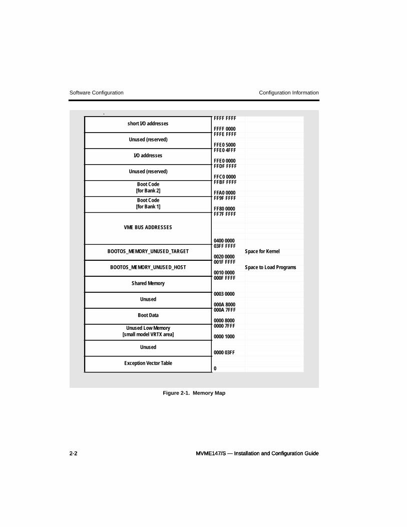
The following memory map (Figure 2-1) uses default mo147 boot PROMs. Themap is defined in mo147.def. If any inconsistencies exist, mo147.def supersedesthis map. This map includes shared memory addresses. If your application does notuse shared memory, use Xconfig to configure the mapping of your own system.
2-2 MVME147/S — Installation and Configuration Guide2-2 MVME147/S — Installation and Configuration Guide2-2 MVME147/S — Installation and Configuration Guide
Software Configuration Configuration Information
Figure 2-1. Memory Map
.
short I/O addressesFFFF FFFF
FFFF 0000
Unused (reserved)FFFE FFFF
FFE0 5000
I/O addressesFFE0 4FFF
FFE0 0000
Unused (reserved)FFDF FFFF
FFC0 0000Boot Code[for Bank 2]
FFBF FFFF
FFA0 0000Boot Code[for Bank 1]
FF9F FFFF
FF80 0000
VME BUS ADDRESSES
FF7F FFFF
0400 0000
BOOTOS_MEMORY_UNUSED_TARGET03FF FFFF
Space for Kernel0020 0000
BOOTOS_MEMORY_UNUSED_HOST001F FFFF
Space to Load Programs0010 0000
Shared Memory000F FFFF
Unused0003 0000
000A 8000
Boot Data000A 7FFF
0000 8000Unused Low Memory
[small model VRTX area]
0000 7FFF
0000 1000
Unused0000 03FF
Exception Vector Table0
MVME147/S — Installation and Configuration Guide 2-3
Configuration Information Software Configuration
Default File
Use the mo147.def default file to configure the system for the bridge in bootPROMs.
Bridge
The logio device to be used as a bridge is logio_ether_1_id (MVME 712 /Ethernet).
Console
By default, the console is logio_serial_1_id (MVME 712 / Serial Port 1).
Device Driver Configuration Parameters
This section describes the timer, serial, Ethernet, and VME device driver configura-tion parameters.
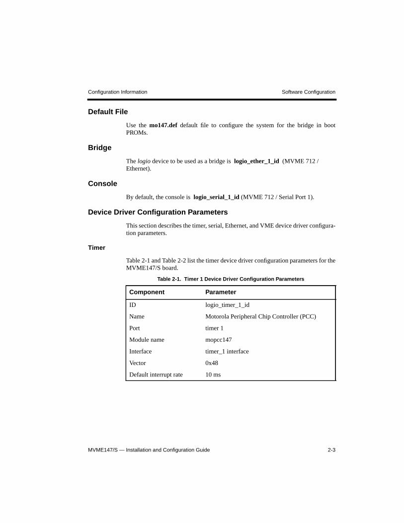
Timer
Table 2-1 and Table 2-2 list the timer device driver configuration parameters for theMVME147/S board.
Table 2-1. Timer 1 Device Driver Configuration Parameters
Component Parameter
ID logio_timer_1_id
Name Motorola Peripheral Chip Controller (PCC)
Port timer 1
Module name mopcc147
Interface timer_1 interface
Vector 0x48
Default interrupt rate 10 ms
2-4 MVME147/S — Installation and Configuration Guide2-4 MVME147/S — Installation and Configuration Guide2-4 MVME147/S — Installation and Configuration Guide
Software Configuration Configuration Information
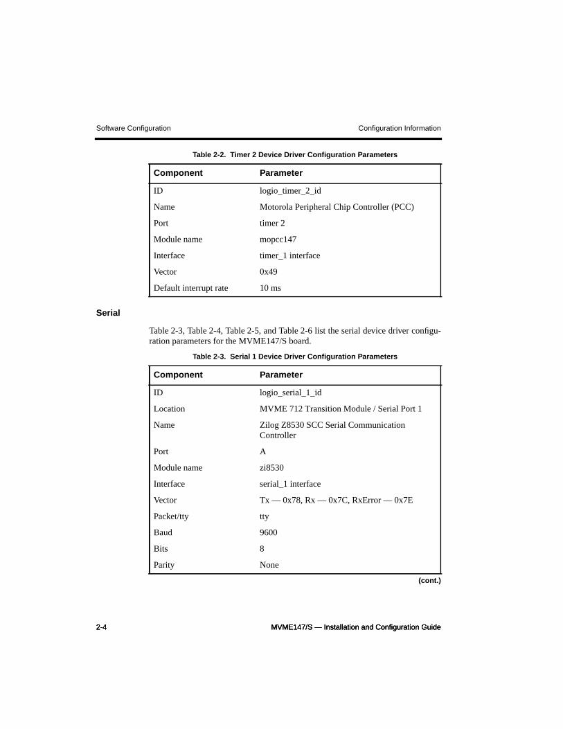
Serial
Table 2-3, Table 2-4, Table 2-5, and Table 2-6 list the serial device driver configu-ration parameters for the MVME147/S board.
Table 2-2. Timer 2 Device Driver Configuration Parameters
Component Parameter
ID logio_timer_2_id
Name Motorola Peripheral Chip Controller (PCC)
Port timer 2
Module name mopcc147
Interface timer_1 interface
Vector 0x49
Default interrupt rate 10 ms
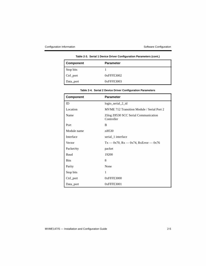
Table 2-3. Serial 1 Device Driver Configuration Parameters
Component Parameter
ID logio_serial_1_id
Location MVME 712 Transition Module / Serial Port 1
Name Zilog Z8530 SCC Serial CommunicationController
Port A
Module name zi8530
Interface serial_1 interface
Vector Tx — 0x78, Rx — 0x7C, RxError — 0x7E
Packet/tty tty
Baud 9600
Bits 8
Parity None
(cont.)
MVME147/S — Installation and Configuration Guide 2-5
Configuration Information Software Configuration
Stop bits 1
Ctrl_port 0xFFFE3002
Data_port 0xFFFE3003
Table 2-4. Serial 2 Device Driver Configuration Parameters
Component Parameter
ID logio_serial_2_id
Location MVME 712 Transition Module / Serial Port 2
Name Zilog Z8530 SCC Serial CommunicationController
Port B
Module name zi8530
Interface serial_1 interface
Vector Tx — 0x70, Rx — 0x74, RxError — 0x76
Packet/tty packet
Baud 19200
Bits 8
Parity None
Stop bits 1
Ctrl_port 0xFFFE3000
Data_port 0xFFFE3001
Table 2-3. Serial 1 Device Driver Configuration Parameters (cont.)
Component Parameter
2-6 MVME147/S — Installation and Configuration Guide2-6 MVME147/S — Installation and Configuration Guide2-6 MVME147/S — Installation and Configuration Guide
Software Configuration Configuration Information
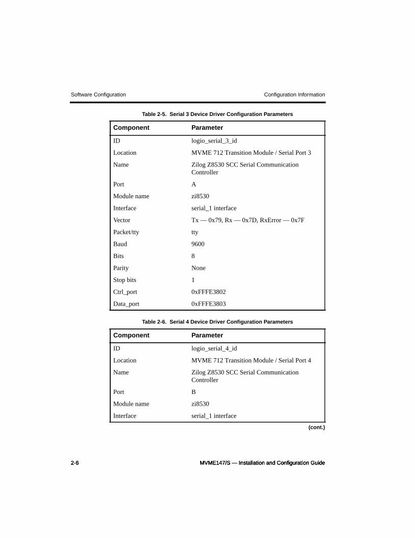
Table 2-5. Serial 3 Device Driver Configuration Parameters
Component Parameter
ID logio_serial_3_id
Location MVME 712 Transition Module / Serial Port 3
Name Zilog Z8530 SCC Serial CommunicationController
Port A
Module name zi8530
Interface serial_1 interface
Vector Tx — 0x79, Rx — 0x7D, RxError — 0x7F
Packet/tty tty
Baud 9600
Bits 8
Parity None
Stop bits 1
Ctrl_port 0xFFFE3802
Data_port 0xFFFE3803
Table 2-6. Serial 4 Device Driver Configuration Parameters
Component Parameter
ID logio_serial_4_id
Location MVME 712 Transition Module / Serial Port 4
Name Zilog Z8530 SCC Serial CommunicationController
Port B
Module name zi8530
Interface serial_1 interface
(cont.)
MVME147/S — Installation and Configuration Guide 2-7
Configuration Information Software Configuration
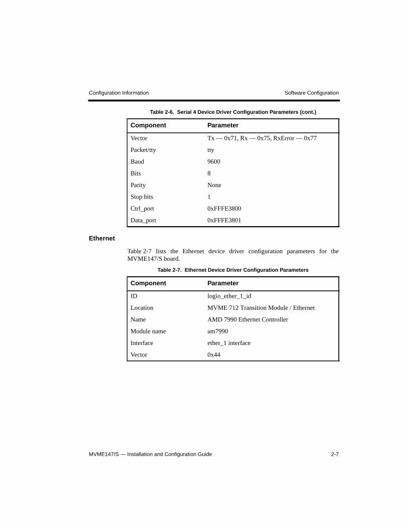
Ethernet
Table 2-7 lists the Ethernet device driver configuration parameters for theMVME147/S board.
Vector Tx — 0x71, Rx — 0x75, RxError — 0x77
Packet/tty tty
Baud 9600
Bits 8
Parity None
Stop bits 1
Ctrl_port 0xFFFE3800
Data_port 0xFFFE3801
Table 2-7. Ethernet Device Driver Configuration Parameters
Component Parameter
ID logio_ether_1_id
Location MVME 712 Transition Module / Ethernet
Name AMD 7990 Ethernet Controller
Module name am7990
Interface ether_1 interface
Vector 0x44
Table 2-6. Serial 4 Device Driver Configuration Parameters (cont.)
Component Parameter
2-8 MVME147/S — Installation and Configuration Guide2-8 MVME147/S — Installation and Configuration Guide2-8 MVME147/S — Installation and Configuration Guide
Software Configuration Configuration Information
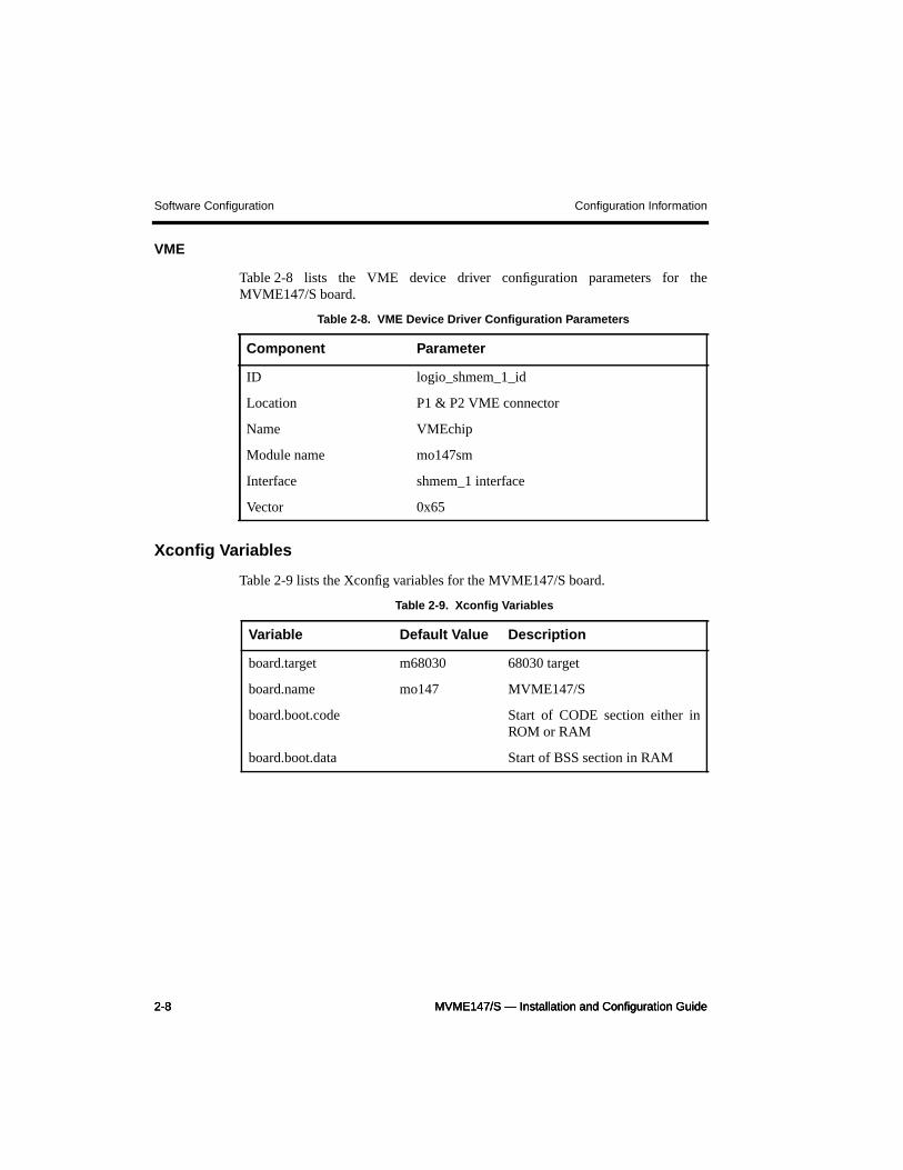
VME
Table 2-8 lists the VME device driver configuration parameters for theMVME147/S board.
Xconfig Variables
Table 2-9 lists the Xconfig variables for the MVME147/S board.
Table 2-8. VME Device Driver Configuration Parameters
Component Parameter
ID logio_shmem_1_id
Location P1 & P2 VME connector
Name VMEchip
Module name mo147sm
Interface shmem_1 interface
Vector 0x65
Table 2-9. Xconfig Variables
Variable Default Value Description
board.target m68030 68030 target
board.name mo147 MVME147/S
board.boot.code Start of CODE section either inROM or RAM
board.boot.data Start of BSS section in RAM
MVME147/S — Installation and Configuration Guide 2-9
Configuration Information Hardware Setup
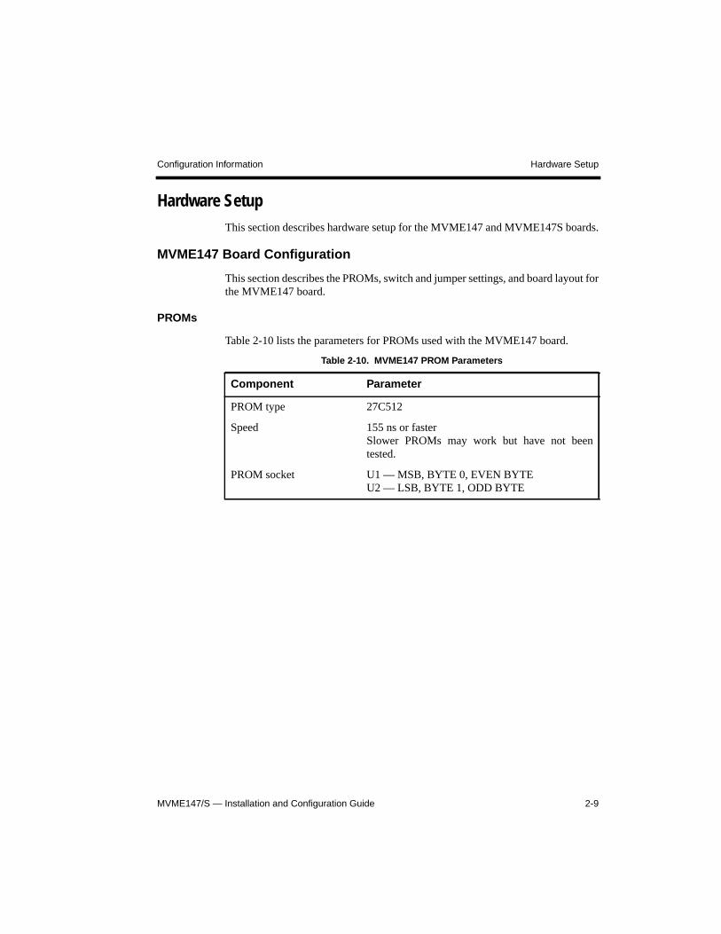
Hardware SetupThis section describes hardware setup for the MVME147 and MVME147S boards.
MVME147 Board Configuration
This section describes the PROMs, switch and jumper settings, and board layout forthe MVME147 board.
PROMs
Table 2-10 lists the parameters for PROMs used with the MVME147 board.
Table 2-10. MVME147 PROM Parameters
Component Parameter
PROM type 27C512
Speed 155 ns or fasterSlower PROMs may work but have not beentested.
PROM socket U1 — MSB, BYTE 0, EVEN BYTEU2 — LSB, BYTE 1, ODD BYTE
2-10 MVME147/S — Installation and Configuration Guide2-10 MVME147/S — Installation and Configuration Guide2-10 MVME147/S — Installation and Configuration Guide
Hardware Setup Configuration Information
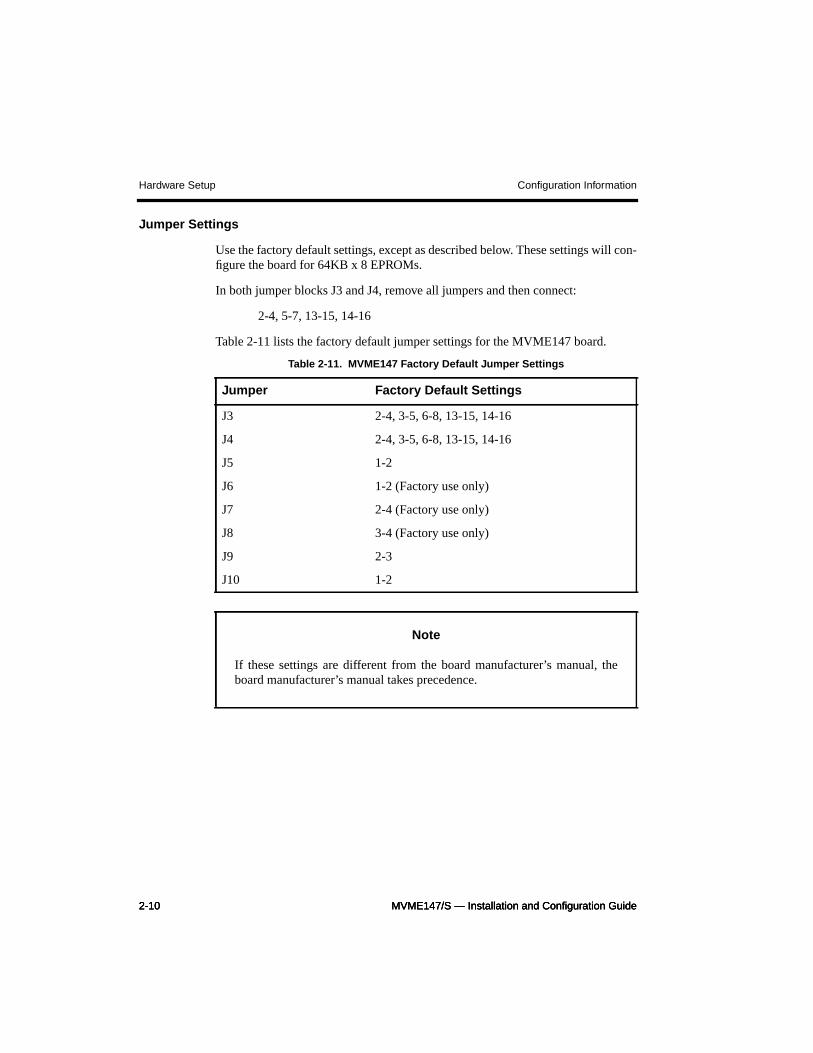
Jumper Settings
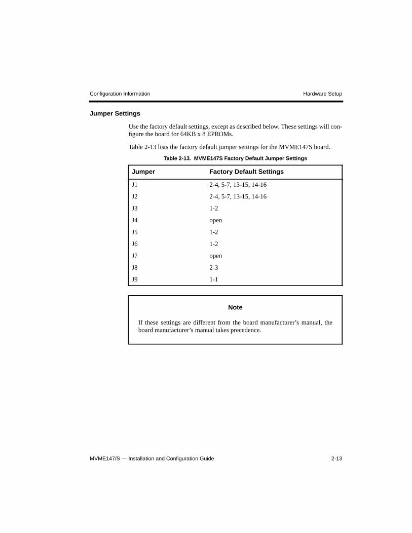
Use the factory default settings, except as described below. These settings will con-figure the board for 64KB x 8 EPROMs.
In both jumper blocks J3 and J4, remove all jumpers and then connect:
2-4, 5-7, 13-15, 14-16
Table 2-11 lists the factory default jumper settings for the MVME147 board.
Table 2-11. MVME147 Factory Default Jumper Settings
Jumper Factory Default Settings
J3 2-4, 3-5, 6-8, 13-15, 14-16
J4 2-4, 3-5, 6-8, 13-15, 14-16
J5 1-2
J6 1-2 (Factory use only)
J7 2-4 (Factory use only)
J8 3-4 (Factory use only)
J9 2-3
J10 1-2
Note
If these settings are different from the board manufacturer’s manual, theboard manufacturer’s manual takes precedence.
MVME147/S — Installation and Configuration Guide 2-11
Configuration Information Hardware Setup
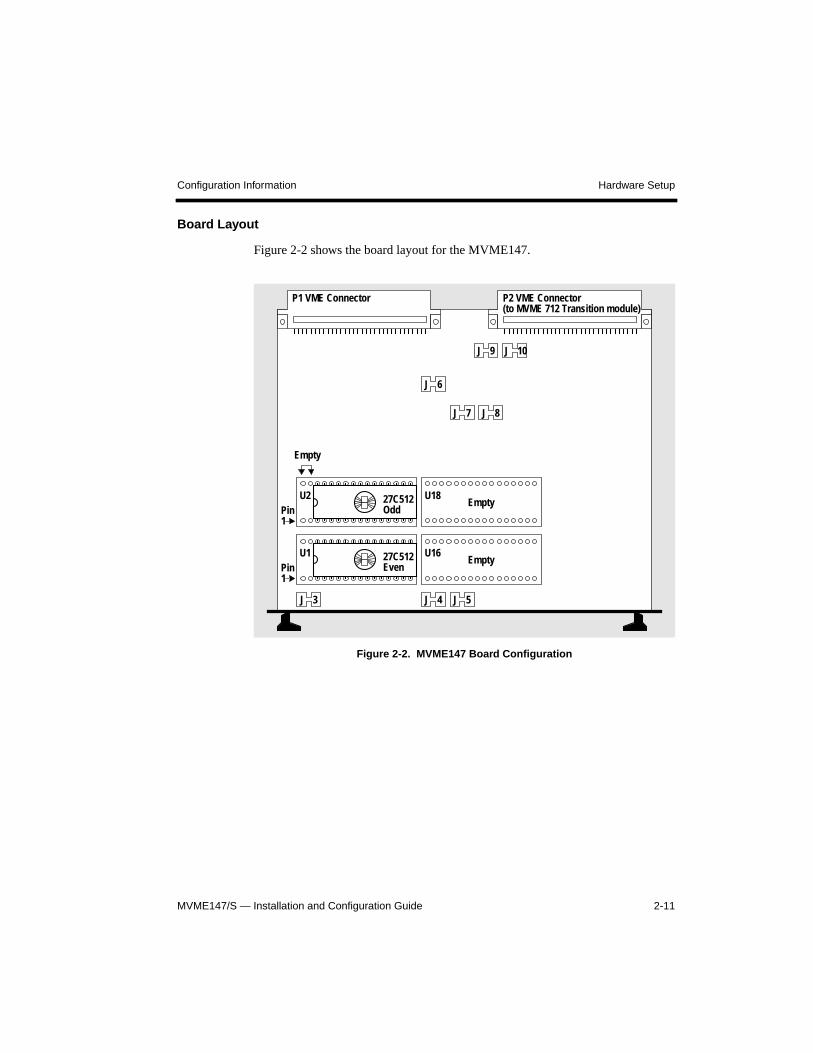
Board Layout
Figure 2-2 shows the board layout for the MVME147.
Figure 2-2. MVME147 Board Configuration
J 3 J 4 J 5
EmptyU2
EmptyPin
Empty
27C512Even
P2 VME Connector(to MVME 712 Transition module)
P1 VME Connector
J 6
J 8
J 10
Pin27C512Odd
1
1
U18
U16U1
J 9
J 7
2-12 MVME147/S — Installation and Configuration Guide2-12 MVME147/S — Installation and Configuration Guide2-12 MVME147/S — Installation and Configuration Guide
Hardware Setup Configuration Information
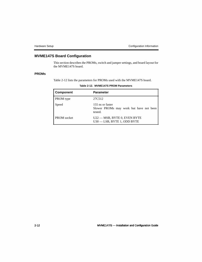
MVME147S Board Configuration
This section describes the PROMs, switch and jumper settings, and board layout forthe MVME147S board.
PROMs
Table 2-12 lists the parameters for PROMs used with the MVME147S board.
Table 2-12. MVME147S PROM Parameters
Component Parameter
PROM type 27C512
Speed 155 ns or fasterSlower PROMs may work but have not beentested.
PROM socket U22 — MSB, BYTE 0, EVEN BYTEU30 — LSB, BYTE 1, ODD BYTE
MVME147/S — Installation and Configuration Guide 2-13
Configuration Information Hardware Setup
Jumper Settings
Use the factory default settings, except as described below. These settings will con-figure the board for 64KB x 8 EPROMs.
Table 2-13 lists the factory default jumper settings for the MVME147S board.
Table 2-13. MVME147S Factory Default Jumper Settings
Jumper Factory Default Settings
J1 2-4, 5-7, 13-15, 14-16
J2 2-4, 5-7, 13-15, 14-16
J3 1-2
J4 open
J5 1-2
J6 1-2
J7 open
J8 2-3
J9 1-1
Note
If these settings are different from the board manufacturer’s manual, theboard manufacturer’s manual takes precedence.
2-14 MVME147/S — Installation and Configuration Guide2-14 MVME147/S — Installation and Configuration Guide2-14 MVME147/S — Installation and Configuration Guide
Hardware Setup Configuration Information
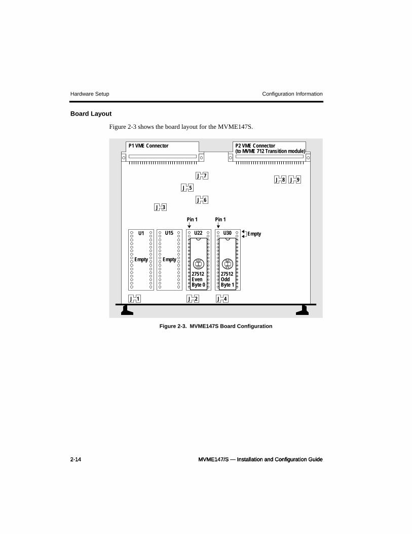
Board Layout
Figure 2-3 shows the board layout for the MVME147S.
Figure 2-3. MVME147S Board Configuration
J 1 J 2 J 4
Empty
U1 U15 U22 U30 Empty
Empty
Pin 1 Pin 1
27512OddByte 1
27512EvenByte 0
P2 VME Connector(to MVME 712 Transition module)
P1 VME Connector
J 3J 6
J 7
J 5
J 8 J 9
MVME147/S — Installation and Configuration Guide 2-15
Configuration Information Supplementary Notes
Supplementary Notes
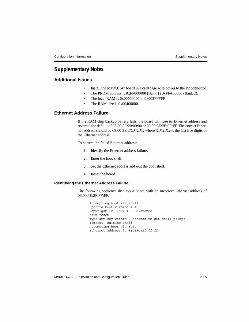
Additional Issues
• Install the MVME147 board in a card cage with power to the P2 connector.• The PROM address is 0xFF800000 (Bank 1) 0xFFA00000 (Bank 2).• The local RAM is 0x00000000 to 0x003FFFFF.• The RAM size is 0x00400000.
Ethernet Address Failure
If the RAM chip backup battery fails, the board will lose its Ethernet address andrevert to the default of 08:00:3E:20:00:00 or 08:00:3E:2F:FF:FF. The correct Ether-net address should be 08:00:3E:2X:XX:XX where X:XX:XX is the last five digits ofthe Ethernet address.
To correct the failed Ethernet address:
1. Identify the Ethernet address failure.
2. Enter the boot shell.
3. Set the Ethernet address and exit the boot shell.
4. Reset the board.
Identifying the Ethernet Address Failure
The following sequence displays a board with an incorrect Ethernet address of08:00:3E:2F:FF:FF:
Attempting boot via shellSpectra Boot version 4.1Copyright (c) 1992-1996 MicrotecWarm resetType any key within 2 seconds to get shell promptTimeout, exiting shellAttempting boot via rarpEthernet address is 8:0:3e:2f:ff:ff
2-16 MVME147/S — Installation and Configuration Guide2-16 MVME147/S — Installation and Configuration Guide2-16 MVME147/S — Installation and Configuration Guide
Supplementary Notes Configuration Information
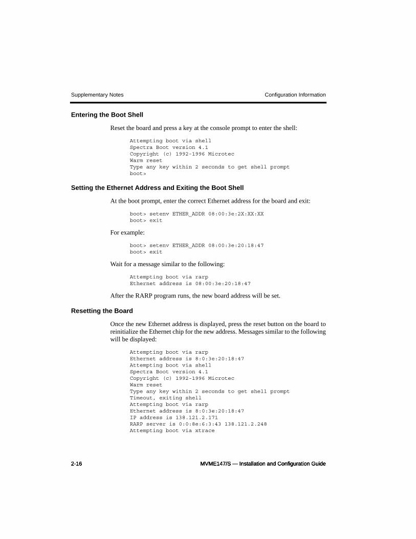
Entering the Boot Shell
Reset the board and press a key at the console prompt to enter the shell:
Attempting boot via shellSpectra Boot version 4.1Copyright (c) 1992-1996 MicrotecWarm resetType any key within 2 seconds to get shell promptboot>
Setting the Ethernet Address and Exiting the Boot Shell
At the boot prompt, enter the correct Ethernet address for the board and exit:
boot> setenv ETHER_ADDR 08:00:3e:2X:XX:XXboot> exit
For example:
boot> setenv ETHER_ADDR 08:00:3e:20:18:47boot> exit
Wait for a message similar to the following:
Attempting boot via rarpEthernet address is 08:00:3e:20:18:47
After the RARP program runs, the new board address will be set.
Resetting the Board
Once the new Ethernet address is displayed, press the reset button on the board toreinitialize the Ethernet chip for the new address. Messages similar to the followingwill be displayed:
Attempting boot via rarpEthernet address is 8:0:3e:20:18:47Attempting boot via shellSpectra Boot version 4.1Copyright (c) 1992-1996 MicrotecWarm resetType any key within 2 seconds to get shell promptTimeout, exiting shellAttempting boot via rarpEthernet address is 8:0:3e:20:18:47IP address is 138.121.2.171RARP server is 0:0:8e:6:3:43 138.121.2.248Attempting boot via xtrace
MVME147/S — Installation and Configuration Guide 2-17
Configuration Information Supplementary Notes
If the battery-backed RAM is operational, this permanently sets the board’s Ether-net address.
Using MVME147Bug to Set the Ethernet Address
If the Motorola MVME147Bug PROMs are available, you can also set the addressusing the lsad command. Consult the MVME147Bug documentation for details.
Cabling to a Serial Port
To use serial communication with the MVME147 board, configure the MVME 712transition module to operate properly with your workstation.
The serial port’s signal assignment is determined by the DTE/DCE configurationselect headers on the MVME712M transition module, which supplies ports for theMVME147. The default setting for ttya (port 1) and ttyb (port 2) have the followingpin 2 and pin 3 signal assignment:
25-pin DSUBConnector Description-------------------------------
2 Receive data3 Transmit data
To connect your target board to a host or terminal whose pin 2 and pin 3 signalassignment is the same as the assignment of the target board, use a serial line withpins 2 and 3 crossed. Alternatively, you can use a straight serial cable with a nullmodem connector.

2-18 MVME147/S — Installation and Configuration Guide2-18 MVME147/S — Installation and Configuration Guide2-18 MVME147/S — Installation and Configuration Guide
Supplementary Notes Configuration Information
1-2 MVME147/S — Installation and Configuration Guide1-2 MVME147/S — Installation and Configuration Guide1-2 MVME147/S — Installation and Configuration Guide
Cabling Establishing the Spectra Connection
CablingIf a console connection is provided or the bridge is serial, use a serial cable to con-nect the target and the host. For details, see the section Cabling to a Serial Port inChapter 2, Configuration Information.
Configuring Ethernet or Serial InterfacesChapter 2, Configuration Information, provides details of the serial or Ethernetinterfaces.
The Bridge for this target is either:
• logio_ether_xx_id (default; see the section Ethernet Connection)
or
• logio_serial_xx_id (see the section Serial Connection)
Ethernet Connection
Assign the board an Ethernet address.
Some boards store the Ethernet address in a nonvolatile or battery backed-up RAMarea. This address may require configuration. For instructions on how to configurethe Ethernet address, see the section Supplementary Notes in Chapter 2, Configura-tion Information.
Assigning the Board an IP Address
If the target board does not have an IP address (this will be the case for new boards),then you or your system administrator must assign one to the board. Consult the net-work and system administration documentation provided by the workstation vendorfor information on this procedure.
MVME147/S — Installation and Configuration Guide 1-3
Establishing the Spectra Connection Configuring Ethernet or Serial Interfaces
Serial Connection
Use the serial_server program to communicate with the target using a serial packetinterface.
To use the serial_server program, perform the following steps:
1. Update the file etc/remote.
2. Update the file $SPECTRA/host/etc/connconf.
3. Start the serial_server program.
Updating /etc/remote
See Chapter 2, Configuration Information, to determine the baud rate, parity, stopbits, and number of bits for the serial bridge device.
Generally, these values are:
• Baud: 19200 (9600 on slower boards)• Parity: none• Stop bits: 1• Bits: 8
Edit the file /etc/remote to create an entry with the above communicationparameters.
1-4 MVME147/S — Installation and Configuration Guide1-4 MVME147/S — Installation and Configuration Guide1-4 MVME147/S — Installation and Configuration Guide
Configuring Ethernet or Serial Interfaces Establishing the Spectra Connection
Example
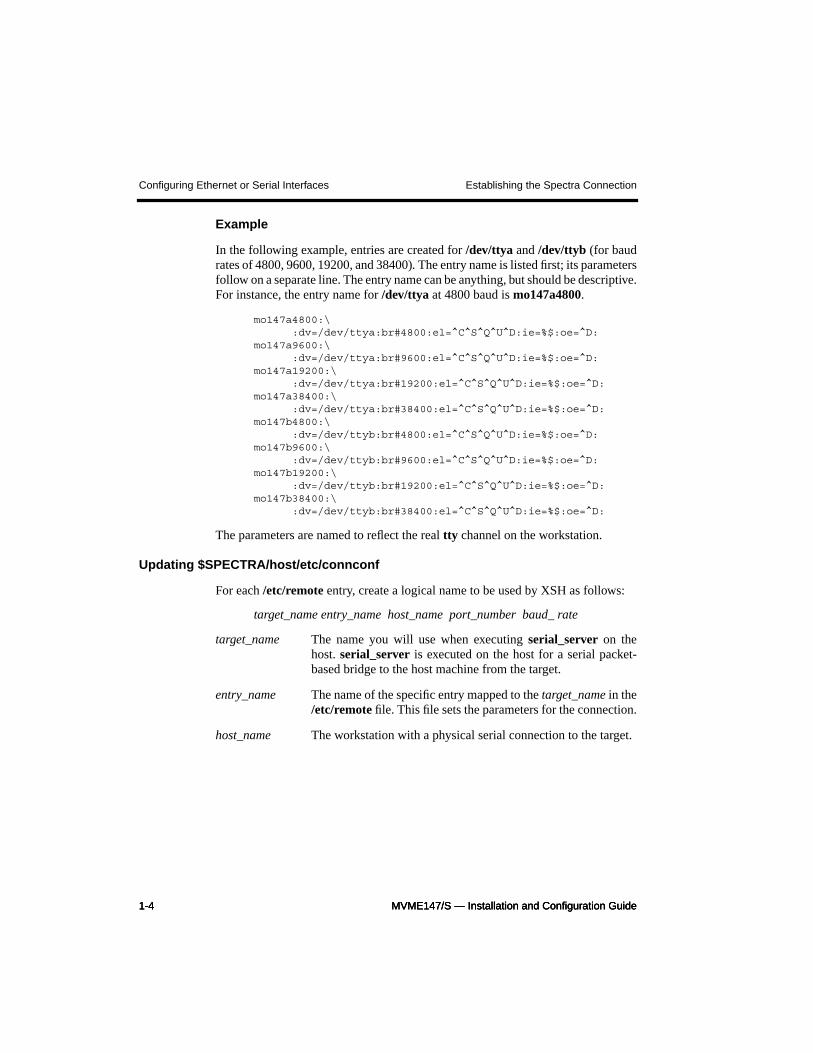
In the following example, entries are created for /dev/ttya and /dev/ttyb (for baudrates of 4800, 9600, 19200, and 38400). The entry name is listed first; its parametersfollow on a separate line. The entry name can be anything, but should be descriptive.For instance, the entry name for /dev/ttya at 4800 baud is mo147a4800.
mo147a4800:\:dv=/dev/ttya:br#4800:el=^C^S^Q^U^D:ie=%$:oe=^D:
mo147a9600:\:dv=/dev/ttya:br#9600:el=^C^S^Q^U^D:ie=%$:oe=^D:
mo147a19200:\:dv=/dev/ttya:br#19200:el=^C^S^Q^U^D:ie=%$:oe=^D:
mo147a38400:\:dv=/dev/ttya:br#38400:el=^C^S^Q^U^D:ie=%$:oe=^D:
mo147b4800:\:dv=/dev/ttyb:br#4800:el=^C^S^Q^U^D:ie=%$:oe=^D:
mo147b9600:\:dv=/dev/ttyb:br#9600:el=^C^S^Q^U^D:ie=%$:oe=^D:
mo147b19200:\:dv=/dev/ttyb:br#19200:el=^C^S^Q^U^D:ie=%$:oe=^D:
mo147b38400:\:dv=/dev/ttyb:br#38400:el=^C^S^Q^U^D:ie=%$:oe=^D:
The parameters are named to reflect the real tty channel on the workstation.
Updating $SPECTRA/host/etc/connconf
For each /etc/remote entry, create a logical name to be used by XSH as follows:
target_name entry_name host_name port_number baud_ rate
target_name The name you will use when executing serial_server on thehost. serial_server is executed on the host for a serial packet-based bridge to the host machine from the target.
entry_name The name of the specific entry mapped to the target_name in the/etc/remote file. This file sets the parameters for the connection.
host_name The workstation with a physical serial connection to the target.
MVME147/S — Installation and Configuration Guide 1-5
Establishing the Spectra Connection Configuring Ethernet or Serial Interfaces
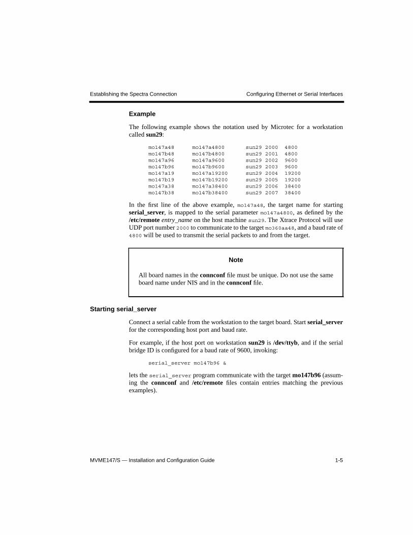
Example
The following example shows the notation used by Microtec for a workstationcalled sun29:
mo147a48 mo147a4800 sun29 2000 4800mo147b48 mo147b4800 sun29 2001 4800mo147a96 mo147a9600 sun29 2002 9600mo147b96 mo147b9600 sun29 2003 9600mo147a19 mo147a19200 sun29 2004 19200mo147b19 mo147b19200 sun29 2005 19200mo147a38 mo147a38400 sun29 2006 38400mo147b38 mo147b38400 sun29 2007 38400
In the first line of the above example, mo147a48, the target name for startingserial_server, is mapped to the serial parameter mo147a4800, as defined by the/etc/remote entry_name on the host machine sun29. The Xtrace Protocol will useUDP port number 2000 to communicate to the target mo360aa48, and a baud rate of4800 will be used to transmit the serial packets to and from the target.
Starting serial_server
Connect a serial cable from the workstation to the target board. Start serial_serverfor the corresponding host port and baud rate.
For example, if the host port on workstation sun29 is /dev/ttyb, and if the serialbridge ID is configured for a baud rate of 9600, invoking:
serial_server mo147b96 &
lets the serial_server program communicate with the target mo147b96 (assum-ing the connconf and /etc/remote files contain entries matching the previousexamples).
Note
All board names in the connconf file must be unique. Do not use the sameboard name under NIS and in the connconf file.
1-6 MVME147/S — Installation and Configuration Guide1-6 MVME147/S — Installation and Configuration Guide1-6 MVME147/S — Installation and Configuration Guide
Connecting to the Target with XSH Establishing the Spectra Connection
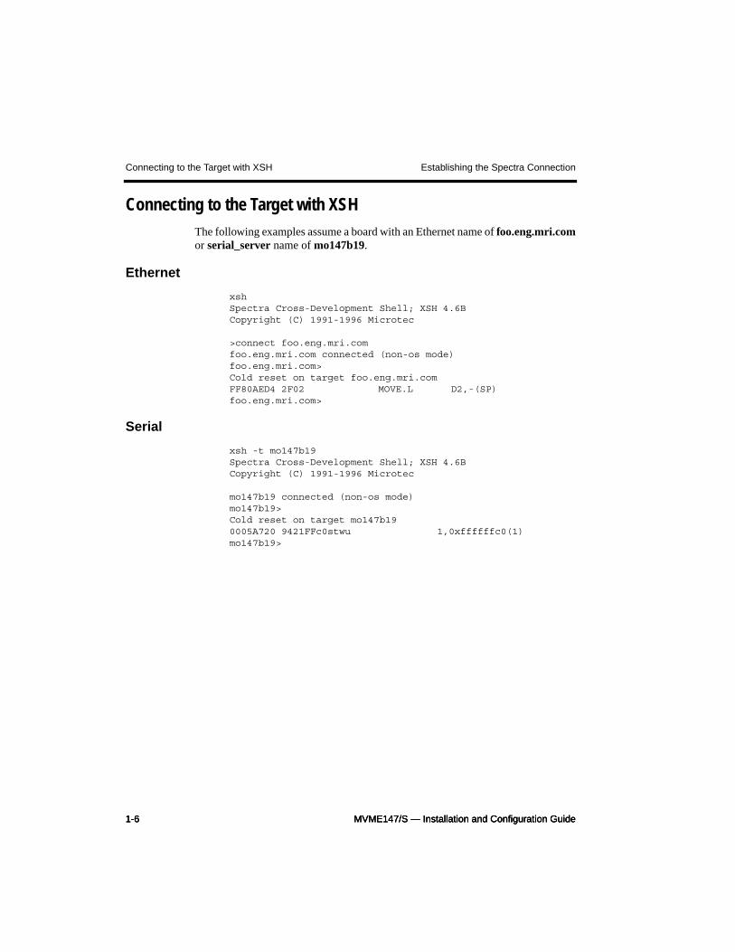
Connecting to the Target with XSHThe following examples assume a board with an Ethernet name of foo.eng.mri.comor serial_server name of mo147b19.
Ethernet
xshSpectra Cross-Development Shell; XSH 4.6BCopyright (C) 1991-1996 Microtec
>connect foo.eng.mri.comfoo.eng.mri.com connected (non-os mode)foo.eng.mri.com>Cold reset on target foo.eng.mri.comFF80AED4 2F02 MOVE.L D2,-(SP)foo.eng.mri.com>
Serial
xsh -t mo147b19Spectra Cross-Development Shell; XSH 4.6BCopyright (C) 1991-1996 Microtec
mo147b19 connected (non-os mode)mo147b19>Cold reset on target mo147b190005A720 9421FFc0stwu 1,0xffffffc0(1)mo147b19>
MVME147/S — Installation and Configuration Guide 1-7
Establishing the Spectra Connection Special Notes for Serial Ports
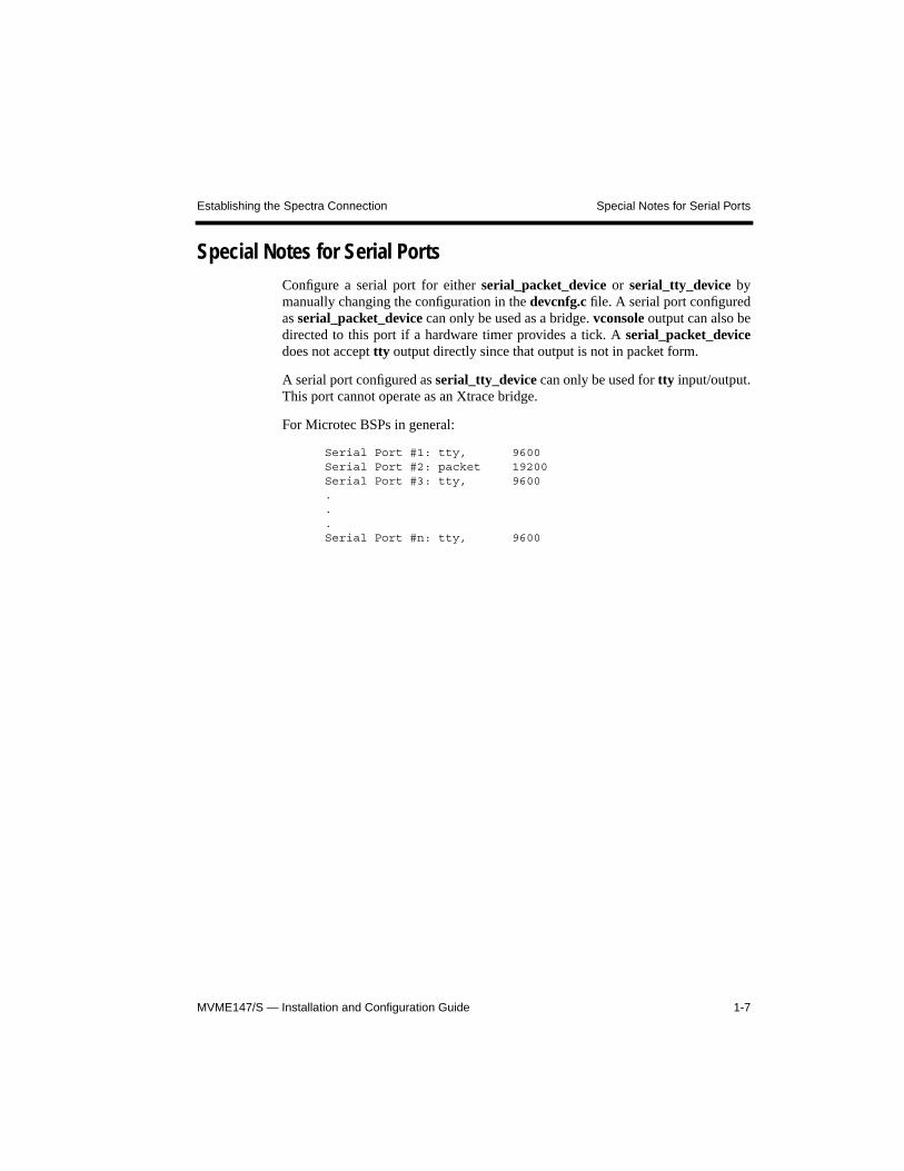
Special Notes for Serial PortsConfigure a serial port for either serial_packet_device or serial_tty_device bymanually changing the configuration in the devcnfg.c file. A serial port configuredas serial_packet_device can only be used as a bridge. vconsole output can also bedirected to this port if a hardware timer provides a tick. A serial_packet_devicedoes not accept tty output directly since that output is not in packet form.
A serial port configured as serial_tty_device can only be used for tty input/output.This port cannot operate as an Xtrace bridge.
For Microtec BSPs in general:
Serial Port #1: tty, 9600Serial Port #2: packet 19200Serial Port #3: tty, 9600...Serial Port #n: tty, 9600

1-8 MVME147/S — Installation and Configuration Guide1-8 MVME147/S — Installation and Configuration Guide1-8 MVME147/S — Installation and Configuration Guide
Special Notes for Serial Ports Establishing the Spectra Connection
System Requirements Preface
MVME147/S — Installation and Configuration Guidevi
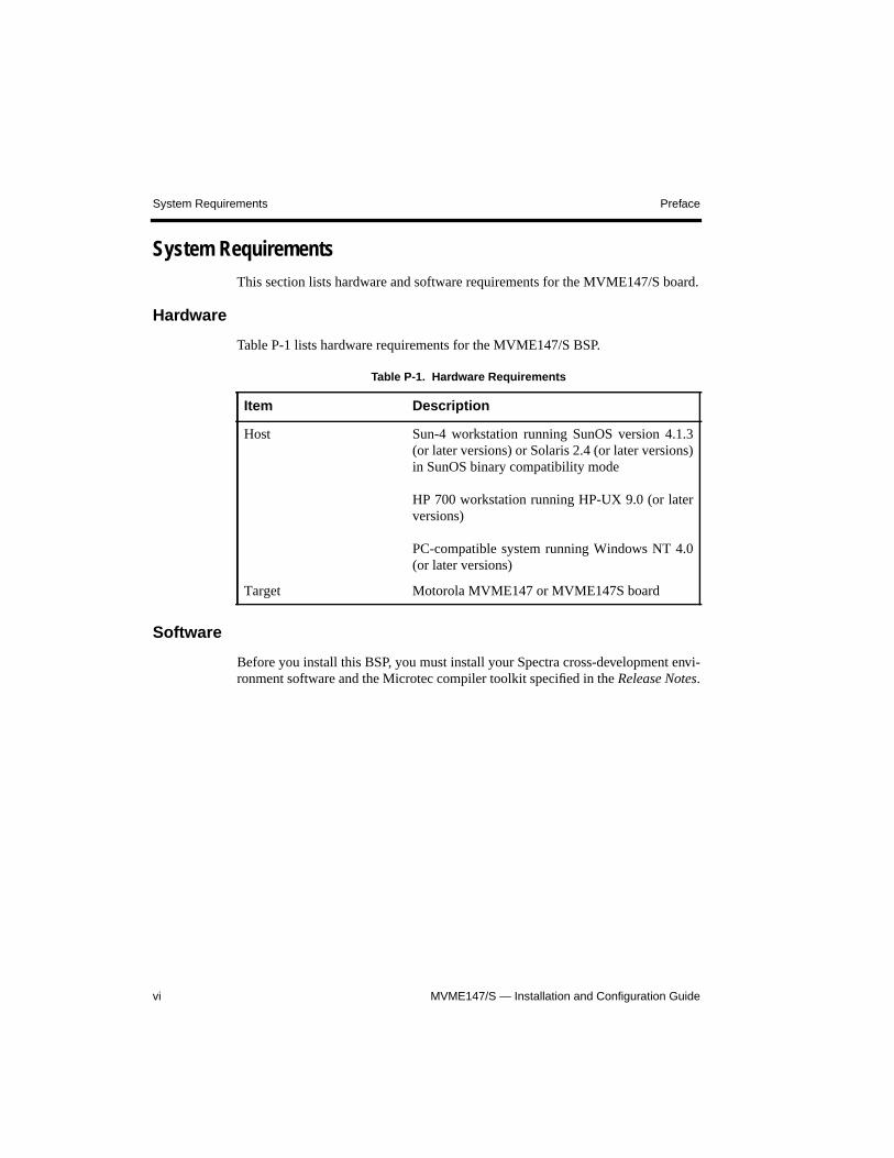
System RequirementsThis section lists hardware and software requirements for the MVME147/S board.
Hardware
Table P-1 lists hardware requirements for the MVME147/S BSP.
Software
Before you install this BSP, you must install your Spectra cross-development envi-ronment software and the Microtec compiler toolkit specified in the Release Notes.
Table P-1. Hardware Requirements
Item Description
Host Sun-4 workstation running SunOS version 4.1.3(or later versions) or Solaris 2.4 (or later versions)in SunOS binary compatibility mode
HP 700 workstation running HP-UX 9.0 (or laterversions)
PC-compatible system running Windows NT 4.0(or later versions)
Target Motorola MVME147 or MVME147S board
Preface Vital Statistics
MVME147/S — Installation and Configuration Guide vii
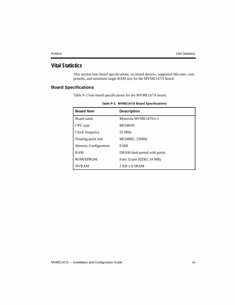
Vital StatisticsThis section lists board specifications, on-board devices, supported Microtec com-ponents, and minimum target RAM size for the MVME147/S board.
Board Specifications
Table P-2 lists board specifications for the MVME147/S board.
Table P-2. MVME147/S Board Specifications
Board Item Description
Board name Motorola MVME147SA-1
CPU type MC68030
Clock frequency 25 MHz
Floating-point unit MC68882, 25MHz
Memory Configuration 8 MB
RAM DRAM dual-ported with parity
ROM/EPROM Four 32-pin JEDEC (4 MB)
NVRAM 2 KB x 8 SRAM
Vital Statistics Preface
MVME147/S — Installation and Configuration Guideviii
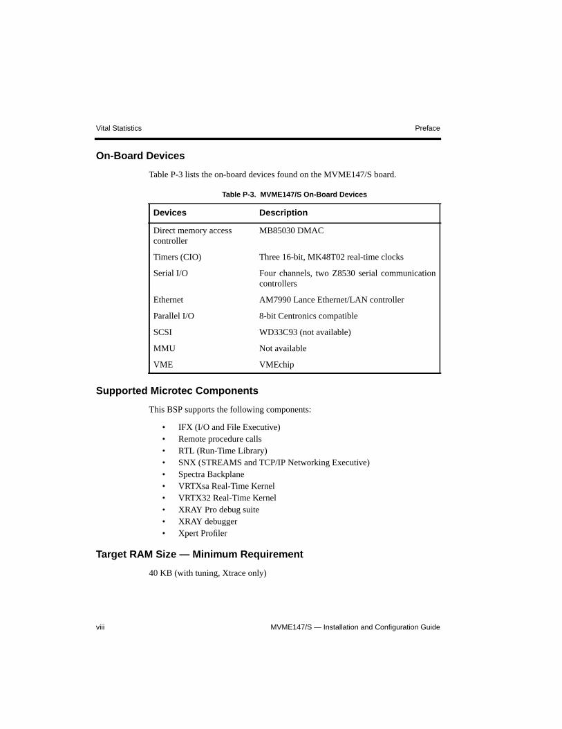
On-Board Devices
Table P-3 lists the on-board devices found on the MVME147/S board.
Supported Microtec Components
This BSP supports the following components:
• IFX (I/O and File Executive)• Remote procedure calls• RTL (Run-Time Library)• SNX (STREAMS and TCP/IP Networking Executive)• Spectra Backplane• VRTXsa Real-Time Kernel• VRTX32 Real-Time Kernel• XRAY Pro debug suite• XRAY debugger• Xpert Profiler
Target RAM Size — Minimum Requirement
40 KB (with tuning, Xtrace only)
Table P-3. MVME147/S On-Board Devices
Devices Description
Direct memory accesscontroller
MB85030 DMAC
Timers (CIO) Three 16-bit, MK48T02 real-time clocks
Serial I/O Four channels, two Z8530 serial communicationcontrollers
Ethernet AM7990 Lance Ethernet/LAN controller
Parallel I/O 8-bit Centronics compatible
SCSI WD33C93 (not available)
MMU Not available
VME VMEchip
Preface Notational Conventions
MVME147/S — Installation and Configuration Guide ix
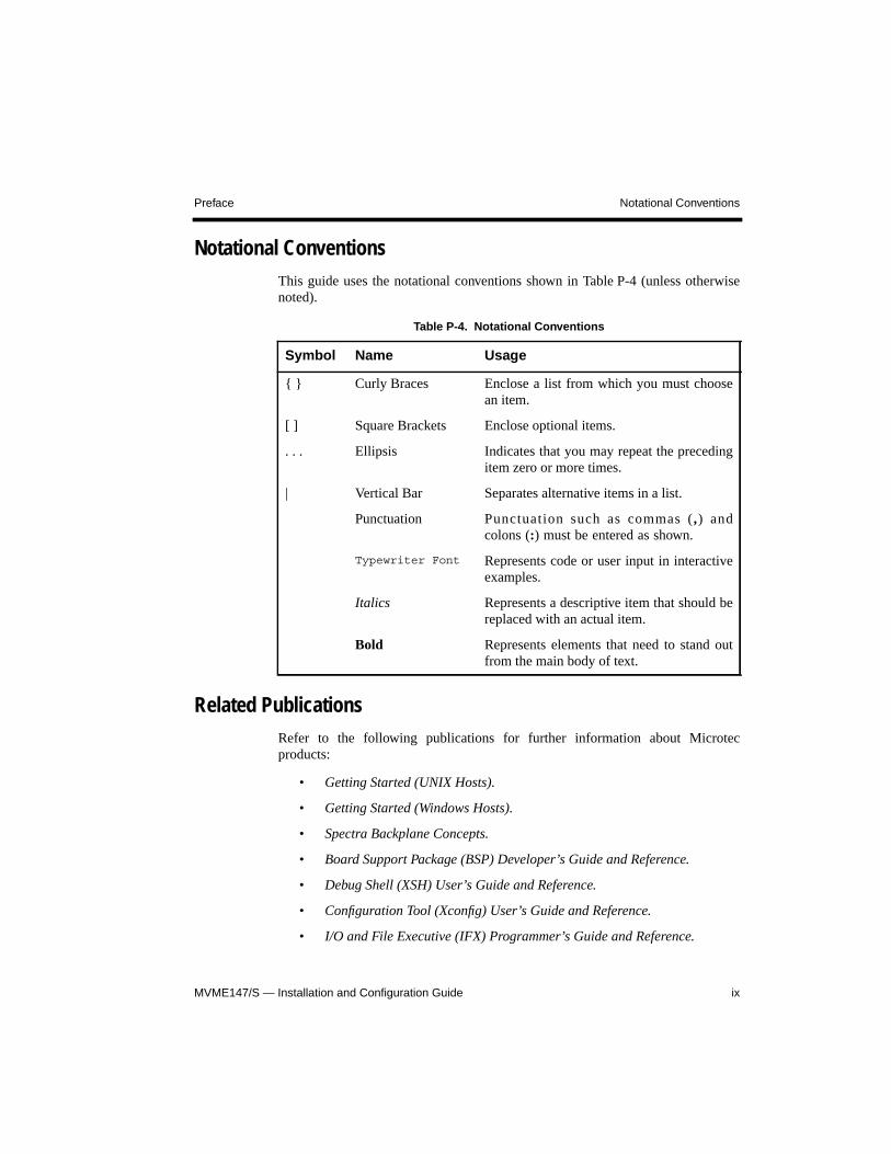
Notational ConventionsThis guide uses the notational conventions shown in Table P-4 (unless otherwisenoted).
Related PublicationsRefer to the following publications for further information about Microtecproducts:
• Getting Started (UNIX Hosts).
• Getting Started (Windows Hosts).
• Spectra Backplane Concepts.
• Board Support Package (BSP) Developer’s Guide and Reference.
• Debug Shell (XSH) User’s Guide and Reference.
• Configuration Tool (Xconfig) User’s Guide and Reference.
• I/O and File Executive (IFX) Programmer’s Guide and Reference.
Table P-4. Notational Conventions
Symbol Name Usage
{ } Curly Braces Enclose a list from which you must choosean item.
[ ] Square Brackets Enclose optional items.
. . . Ellipsis Indicates that you may repeat the precedingitem zero or more times.
| Vertical Bar Separates alternative items in a list.
Punctuation Punctuation such as commas (,) andcolons (:) must be entered as shown.
Typewriter Font Represents code or user input in interactiveexamples.
Italics Represents a descriptive item that should bereplaced with an actual item.
Bold Represents elements that need to stand outfrom the main body of text.
Questions and Suggestions Preface
MVME147/S — Installation and Configuration Guidex
• STREAMS and TCP/IP Networking Executive (SNX) and SNMP Program-mer’s Guide and Reference.
• Run-Time Library (RTL) Programmer’s Guide and Reference.
Questions and SuggestionsMicrotec is committed to providing its customers with quality software develop-ment and RTOS tools and support services. Our commitment continues beyondyour purchase of the product throughout your development life cycle.
If you have questions or suggestions regarding this product, please contact yourMicrotec support representative. Contact numbers are listed on the back cover ofthis document.
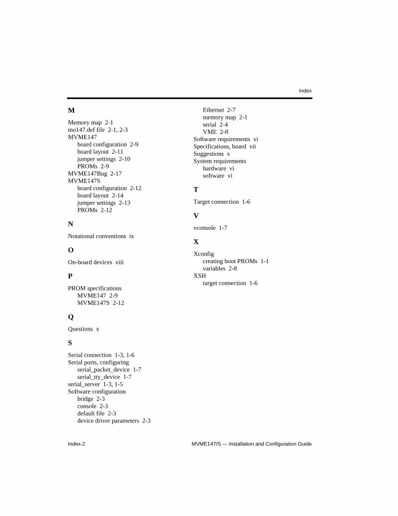
MVME147/S — Installation and Configuration GuideIndex-2
Index
M
Memory map 2-1mo147.def file 2-1, 2-3MVME147
board configuration 2-9board layout 2-11jumper settings 2-10PROMs 2-9
MVME147Bug 2-17MVME147S
board configuration 2-12board layout 2-14jumper settings 2-13PROMs 2-12
N
Notational conventions ix
O
On-board devices viii
P
PROM specificationsMVME147 2-9MVME147S 2-12
Q
Questions x
S
Serial connection 1-3, 1-6Serial ports, configuring
serial_packet_device 1-7serial_tty_device 1-7
serial_server 1-3, 1-5Software configuration
bridge 2-3console 2-3default file 2-3device driver parameters 2-3
Ethernet 2-7memory map 2-1serial 2-4VME 2-8
Software requirements viSpecifications, board viiSuggestions xSystem requirements
hardware visoftware vi
T
Target connection 1-6
V
vconsole 1-7
X
Xconfigcreating boot PROMs 1-1variables 2-8
XSHtarget connection 1-6

LOT-18 MVME147/S — Installation and Configuration Guide

LOF-16 MVME147/S — Installation and Configuration Guide
MVME147/S — Installation and Configuration Guide
Contents
xii
Serial ................................................................................................................... 2-4Ethernet ............................................................................................................... 2-7VME .................................................................................................................... 2-8
Xconfig Variables ..................................................................................................... 2-8Hardware Setup ............................................................................................................... 2-9
MVME147 Board Configuration .............................................................................. 2-9PROMs ................................................................................................................ 2-9Jumper Settings ................................................................................................. 2-10Board Layout .................................................................................................... 2-11
MVME147S Board Configuration .......................................................................... 2-12PROMs .............................................................................................................. 2-12Jumper Settings ................................................................................................. 2-13Board Layout .................................................................................................... 2-14
Supplementary Notes .................................................................................................... 2-15Additional Issues ..................................................................................................... 2-15Ethernet Address Failure ......................................................................................... 2-15
Identifying the Ethernet Address Failure .......................................................... 2-15Entering the Boot Shell ..................................................................................... 2-16Setting the Ethernet Address and Exiting the Boot Shell ................................. 2-16Resetting the Board ........................................................................................... 2-16
Using MVME147Bug to Set the Ethernet Address ................................................ 2-17Cabling to a Serial Port ........................................................................................... 2-17
Index ................................................................................................................................... Index-1
Figures
Figure 2-1. Memory Map ...................................................................................................... 2-2Figure 2-2. MVME147 Board Configuration ...................................................................... 2-11Figure 2-3. MVME147S Board Configuration .................................................................... 2-14
Tables
Table P-1. Hardware Requirements ........................................................................................ viTable P-2. MVME147/S Board Specifications ..................................................................... vii
Contents
MVME147/S — Installation and Configuration Guide xiii
Table P-3. MVME147/S On-Board Devices ........................................................................ viiiTable P-4. Notational Conventions ........................................................................................ ixTable 2-1. Timer 1 Device Driver Configuration Parameters .............................................. 2-3Table 2-2. Timer 2 Device Driver Configuration Parameters .............................................. 2-4Table 2-3. Serial 1 Device Driver Configuration Parameters .............................................. 2-4Table 2-4. Serial 2 Device Driver Configuration Parameters .............................................. 2-5Table 2-5. Serial 3 Device Driver Configuration Parameters .............................................. 2-6Table 2-6. Serial 4 Device Driver Configuration Parameters .............................................. 2-6Table 2-7. Ethernet Device Driver Configuration Parameters ............................................. 2-7Table 2-8. VME Device Driver Configuration Parameters .................................................. 2-8Table 2-9. Xconfig Variables ............................................................................................... 2-8Table 2-10. MVME147 PROM Parameters ........................................................................... 2-9Table 2-11. MVME147 Factory Default Jumper Settings ................................................... 2-10Table 2-12. MVME147S PROM Parameters ....................................................................... 2-12Table 2-13. MVME147S Factory Default Jumper Settings ................................................. 2-13

MVME147/S — Installation and Configuration Guide
Contents
xiv
TRADEMARKS
ARTX/ADA Realtime Executive, Microtec, the Microtec logo, Nanokernel, RTscope,RTsource, Spectra, VRTX, VRTX32, VRTXvelocity, XRAY, Xtrace, and XtraceProtocol are registered trademarks of Microtec.
BSPBuilder, FastStart, IFX, KernelBuilder, KernelIntegrator, logio, SNX, SourceExplorer, the Spectra logo, Target Manager, TNX, ToolBuilder, Virtual Target,VRTXmc, VRTX/OS, VRTXsa, Xconfig, Xpert, Xpert Profiler, XRAY In-CircuitDebugger, XRAY In-Circuit Debugger Monitor, and XSH are trademarks of Microtec.
Other product names mentioned are trademarks or registered trademarks of their respectivecompanies.
RESTRICTED RIGHTS LEGEND
U.S. Government Restricted Rights. This product and related documentation have been developedentirely at private expense and are commercial computer software provided with RESTRICTEDRIGHTS. Use, duplication or disclosure by the U.S. Government or a U.S. Governmentsubcontractor is subject to the restrictions set forth in the license agreement provided with theproduct pursuant to DFARS 227.7202-3(a) or as set forth in subparagraph (c)(1) and (2) of theCommercial Computer Software - Restricted Rights clause at FAR 52.227-19, as applicable.
Microtec880 Ridder Park Dr. San Jose, CA 95131
Copyright 1987-1997 Microtec. All rights reserved. No part of this publication may bereproduced, transmitted, or translated, in any form or by any means, electronic, mechanical,manual, optical or otherwise, without prior written permission of Microtec.
00
ii MVME147/S — Installation and Configuration Guide
Revision History
MVME147/S — Installation and Configuration Guide iii
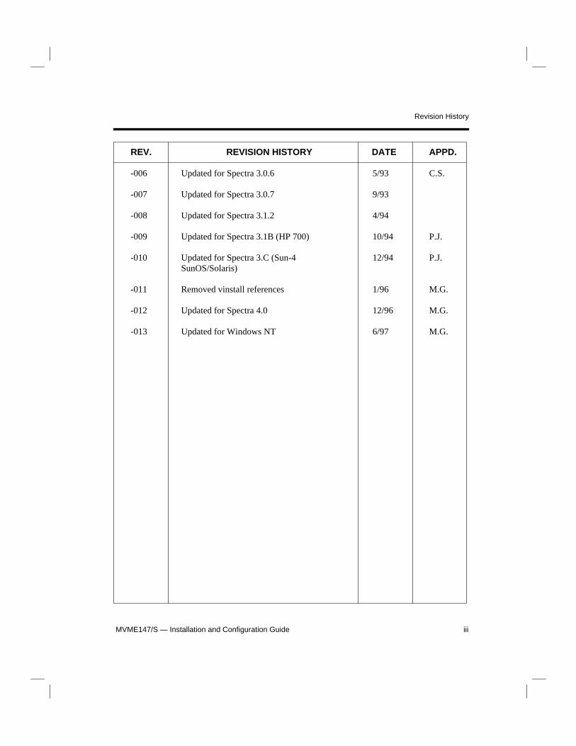
REV. REVISION HISTORY DATE APPD.
-006 Updated for Spectra 3.0.6 5/93 C.S.
-007 Updated for Spectra 3.0.7 9/93
-008 Updated for Spectra 3.1.2 4/94
-009 Updated for Spectra 3.1B (HP 700) 10/94 P.J.
-010 Updated for Spectra 3.C (Sun-4 12/94 P.J.SunOS/Solaris)
-011 Removed vinstall references 1/96 M.G.
-012 Updated for Spectra 4.0 12/96 M.G.
-013 Updated for Windows NT 6/97 M.G.

Revision History
iv MVME147/S — Installation and Configuration Guide