Embed Size (px)
Citation preview
Distributed Power in Telecom, Industrial Control, Wireless, & Computer Applications
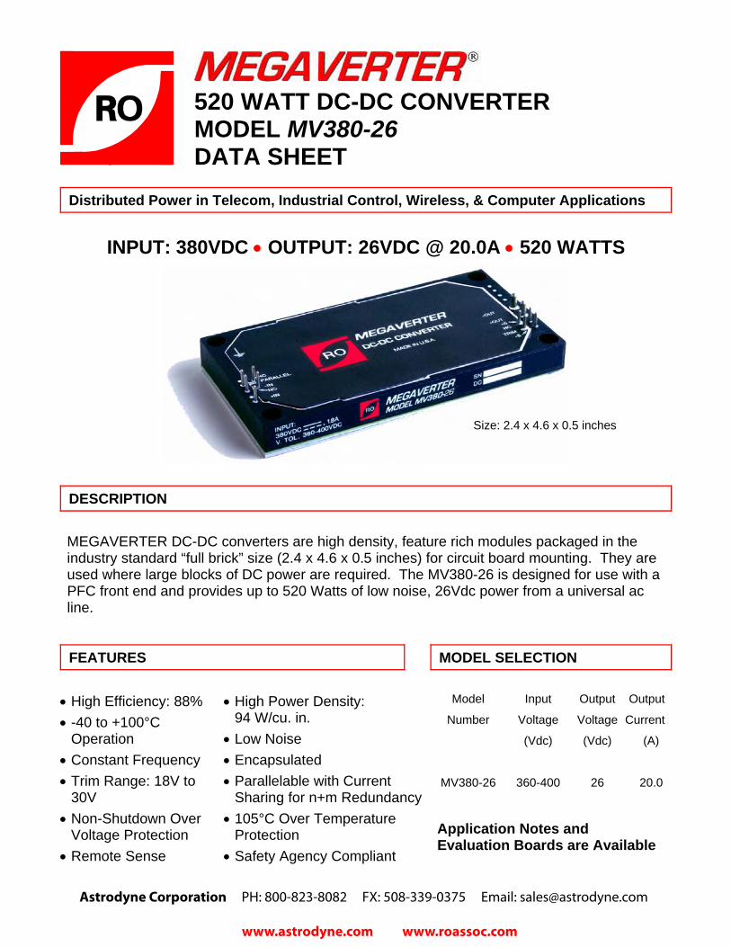
INPUT: 380VDC • OUTPUT: 26VDC @ 20.0A • 520 WATTS
DESCRIPTION
MEGAVERTER DC-DC converters are high density, feature rich modules packaged in the industry standard “full brick” size (2.4 x 4.6 x 0.5 inches) for circuit board mounting. They are used where large blocks of DC power are required. The MV380-26 is designed for use with a PFC front end and provides up to 520 Watts of low noise, 26Vdc power from a universal ac line.
FEATURES MODEL SELECTION
• High Efficiency: 88% • -40 to +100°C
Operation• Constant Frequency • Trim Range: 18V to
30V• Non-Shutdown Over
Voltage Protection • Remote Sense
• High Power Density: 94 W/cu. in.
• Low Noise • Encapsulated • Parallelable with Current
Sharing for n+m Redundancy • 105°C Over Temperature
Protection• Safety Agency Compliant
Model Input Output Output
Number Voltage Voltage Current
(Vdc) (Vdc) (A)
MV380-26 360-400 26 20.0
Application Notes and Evaluation Boards are Available
520 WATT DC-DC CONVERTER MODEL MV380-26DATA SHEET
Size: 2.4 x 4.6 x 0.5 inches
Astrodyne Corporation PH: 800-823-8082 FX: 508-339-0375 Email: [email protected]
www.astrodyne.com www.roassoc.com

MEGAVERTER® DC-DC Converter MV380-26
ELECTRICAL SPECIFICATIONS (continued)
ISOLATION PARAMETERS MIN TYP MAX UNITS CONDITIONS Input/Output Isolation 4500 Vdc Input/Baseplate Isolation 2500 Vdc Output/Baseplate Isolation 500 Vdc Input-to-Output Capacitance 4300 pF Case Floating Input-to-Output Resistance 10 M Ohms
MECHANICAL PARAMETERS MIN TYP MAX UNITS CONDITIONS ).zo( g )4.7( 032 thgieW
gniwarD eniltuO eeS sehcnI 6.4 x 4.2 x 5.0 eziSThermal Resistance, Case-to-Ambient
3.3 °C/W Case Temperature = 100 °C
FEATURE PARAMETERS MIN TYP MAX UNITS CONDITIONS Power Sharing Accuracy ±5 %F.L. 10 to 100% Full Load (F.L.)
V02<cdV rof daol .nim Am002** cdV 03 **81 egnaR mirTRemote Sense Compensation 0.5 Vdc Over Voltage Protection (Non-Shutdown, Auto. Recovery)
30 36 Vdc 25 °C Case
Over Temperature Shut-down +100 +105 +110 °C Case Temperature V ,.L.F cesm 006 emiT nO-nruT out within 1% of Steady State
* elbanELogic Off Threshold 0.8 V Vout = 0 Enable Current (Logic Off) 1.0 mA @Venable = 0 V Logic On Threshold 2.4 V Turn-On Time 2.0 msec F.L., Vout within 1% of Steady State
* An open collector connection or equivalent is recommended for on/off control.
TRIM CIRCUIT CONFIGURATIONS TRIM RESISTOR CALCULATIONS
kohmsV
V67.276.32uptrim ��
�
����
�∆
∆×−=−
o
oR
kohmsV
V15.780.308downtrim ��
�
����
�∆
∆×−=−
o
oRRtrim-up
+Out
+Sense
Trim
-Sense
-Out
Load
Trim Up
Rtrim-down
+Out
+Sense
Trim
-Sense
-Out
Load
Trim Down
(Volts)Change VoltageOutputDesiredVo =∆
ouptrim VIncreaseto ValueResistorExternal=−R
odowntrim VDecreaseto ValueResistorExternal=−R
Astrodyne Corporation PH: 800-823-8082 FX: 508-339-0375 Email: [email protected]
www.astrodyne.com www.roassoc.com

MEGAVERTER® DC-DC Converter MV380-26
ABSOLUTE MAXIMUM RATINGS
SNOITIDNOC STINU XAM NIM RETEMARAP cdV 024 3.0- )nI– ot nI+( egatloV tupnI
Enable Voltage (Enable to –In) -0.3 6.0 Vdc Parallel Pin Voltage (Parallel Pin to –In) -0.3 5.0 Vdc
C° 521+ 55- erutarepmeT egarotS etalpesaB C° 001+ 04- erutarepmeT gnitarepO
Soldering Temperature (Wave Solder) 260 °C < 5 sec. Soldering Temperature (Hand Solder) 390 °C < 7 sec.
ELECTRICAL SPECIFICATIONS
INPUT PARAMETERS MIN TYP MAX UNITS CONDITIONS cdV 004 083 063 egatloV tupnI
Maximum Input Current 2.5 A See Input Characteristic Curve Input Ripple Rejection 60 dB @120 Hz
OUTPUT PARAMETERS MIN TYP MAX UNITS CONDITIONS Voltage Set Point 25.75 26 26.25 Vdc 380 Vin, 25°C, Full Load
daoL lluF ot A 0 % 6.0 3.0 noitalugeR daoLV revO % 1.0 20.0 noitalugeR eniL in Range
Voltage Drift w/Temperature 0.02 %/°C -40 to +100 °C zHM 02 ot zH 5 p-pV% 2 1 elppiR
A 0.02 0 tnerruC detaR W 025 rewoP tuptuO
Current Limit Inception 115 120 130 % F.L. Vout = 95% Vout nominal
Short Circuit Current 150 % F.L. Vout = 250 mV
Transient Response Peak Deviation (0.5A/µsec slew rate)
5 % Vout Load Change from 25% to 75% to 25% Full Load
Transient Response Settling Time (0.5 A/µsec slew rate)
100 µsec Vout within 1% Vout nominal
V % 88 ycneiciffE in = 380 V, Full Load, 70 °C Case
External Load Capacitance 0 3,300 µF
Exceeding absolute maximum ratings may cause permanent damage and may reduce reliability.
Electrical specifications apply over the entire range of input voltage, output current, and temperature unless indicated.
Astrodyne Corporation PH: 800-823-8082 FX: 508-339-0375 Email: [email protected]
www.astrodyne.com www.roassoc.com

MEGAVERTER® DC-DC Converter MV380-26
Efficiency Transient Response
Effic
ienc
y (%
)
65
70
75
80
85
90
95
0 5 10 15 20
-30
-20
-10
0
10
20
30
-50 -40 -30 -20 -10 0 10 20 30 40 50t, 50µsec/div
1V/d
iv.
Load Current (Amps) Iout = 5A – 15A – 5A Current Slew Rate = 0.5A/µsec
Outline Drawing
4.30
4.604.20
.56
.20 MIN.
.040 DIA. PIN 9 PLACES
.12
.15
.202.40
.15.27
PARALLELNC
+IN
.20
.50
ALUMINUM HEATSINKSURFACE
.20 .28 DIA. X .19 DEEP4 PLACES
.098 DIA. PIN2 PLACES
+OUT-OUT
TRIMNC +S
-S
2.00.25
.15
.20
.143 DIA. THRU4 PLACES
Vin = 380V
Astrodyne Corporation PH: 800-823-8082 FX: 508-339-0375 Email: [email protected] Hampden RdMans�eld, MA 02048
www.astrodyne.com www.roassoc.com