Embed Size (px)
Citation preview
1
TC220S TIRE CHANGER
INSTRUCTION MANUAL
2
WARNING
This instruction manual is the important part of the product. Please read it carefully and keep it properly.
This machine is only applied to mount, demount and inflate the tire in the specified scope and not for any other
purpose.
The manufacturer will not be responsible for the damage or injury caused for the operation not properly and out of
the range.
NOTE
This machine should be operated by the special trained qualified personnel. When operating, the unauthorized
personnel will be kept far away from the machine.
Please note the safety label stuck on the machine.
Operators should wear safety protective facilities such as working suit, protective glasses and safety shoes. Keep
your hands and body from the movable parts as possible as you can. Necklace, bracelet and loosen clothing may
cause dangerous to the operators.
Tire changer should be installed and fixed on the flat and solid ground. The more than 0.5m of distance from the rear
and lateral side of the machine to the wall can guarantee the perfect air flow and enough operation space.
Do not place the machine in the site of high temperature, high humidity, dust and with flammable and corrosion gas.
Without the permission from the manufacturer, any change on the machine parts will cause injury/damage to the
machine/operator.
Pay attention that the tire changer should be operated under the specified voltage and air pressure.
If you want to move the tire changer, you should under the guidance of the professional service personnel.
3
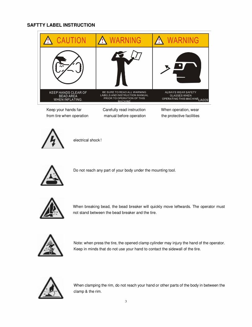
SAFTTY LABEL INSTRUCTION
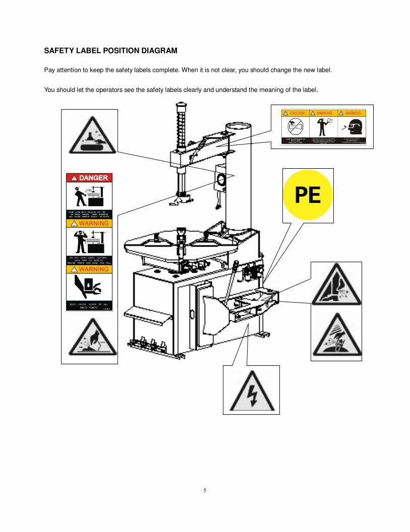
Keep your hands far Carefully read instruction When operation, wear
from tire when operation manual before operation the protective facilities
electrical shock!
Do not reach any part of your body under the mounting tool.
When breaking bead, the bead breaker will quickly move leftwards. The operator must
not stand between the bead breaker and the tire.
Note: when press the tire, the opened clamp cylinder may injury the hand of the operator.
Keep in minds that do not use your hand to contact the sidewall of the tire.
When clamping the rim, do not reach your hand or other parts of the body in between the
clamp & the rim.
4
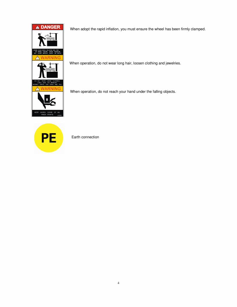
When adopt the rapid inflation, you must ensure the wheel has been firmly clamped.
When operation, do not wear long hair, loosen clothing and jewelries.
When operation, do not reach your hand under the falling objects.
Earth connection
5
SAFETY LABEL POSITION DIAGRAM
Pay attention to keep the safety labels complete. When it is not clear, you should change the new label.
You should let the operators see the safety labels clearly and understand the meaning of the label.

6
INDEX
CHAPTER 1 GENERAL DESCRIPTION……………………………………….………………………………7
CHAPTER 2 MAIN PARTS………….……………………………..…………………………………………….7
CHAPTER 3 OPERATION……….……………………………………………..………………………….….….8
CHAPTER 4 MAINTENANCE AND REPAIR………..……………………...……………………………...…10
CHAPTER 5 TRANSPORTATION…………..….…………..........…………………………………………….…11
CHAPTER 6 CIRCUIT DIAGRAM……………………………………………..…….…………………………….12
CHAPTER 7 TROUBLESHOOTING …….………………..…………....…………..…………………………….13
7
CHAPTER 1 GENERAL DESCRIPTION
1.1PRODUCT INTRODUCTION
This series of equipment is the tire changer with fixed
column and rocker arm. It is suitable to mount, demount
and inflate all basic tires with tube & tubeless. The
operation is easy, convenient, safety and reliable. It is
the necessary equipment for the auto service shop and
tire shop. The model is MV104E.
1.2EQUIPMENT BASIC DIMENSION
Model H(mm) L(mm) W(mm) NW(kg)
MV104E 1820 985 780 225
1.3 TECHNICAL DATA
Operation pressure:8-10bar
Motor:60Hz 110V 1.1Kw
RPM of turntable:6rpm
Noise:<75dB
1.4 APPLICATION SCOPE
Model Wheel diameter
(Max.)
Wheel width
(Max.)
Rim Clamp
MV104E 960mm(37″) 304mm(12″) 10″- 20″
12″- 23″
1.5ENVIRONMENT REQUIREMENT
Ambient temperature: 0℃~45℃
Relative humidity: 30 -95%
Sea leve: max.1000m
Without dust and flammable and explosive gas, the
operation space around the machine will not smaller
than the indicated in FIG 1. If the machine is installed
outdoors, it must have the protective shed to avoid
being exploded to the rain and sunlight.
It is forbidden to use in the site with the
flammable gas!!!!
FIG 1
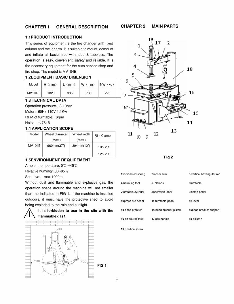
CHAPTER 2 MAIN PARTS
Fig 2
1vertical rod spring 2rocker arm 3 vertical hexangular rod
4mounting tool 5. clamps 6turntable
7turntable cylinder 8operation label 9clamp pedal
10press tire pedal 11 turntable pedal 12 lever
13 bead breaker 14 bead breaker piston 15bead breaker support
16 air source inlet 17lock handle 18 column
19 position screw
8
CHAPTER 3 OPERATION
3.1 DEMOUNT TIRE
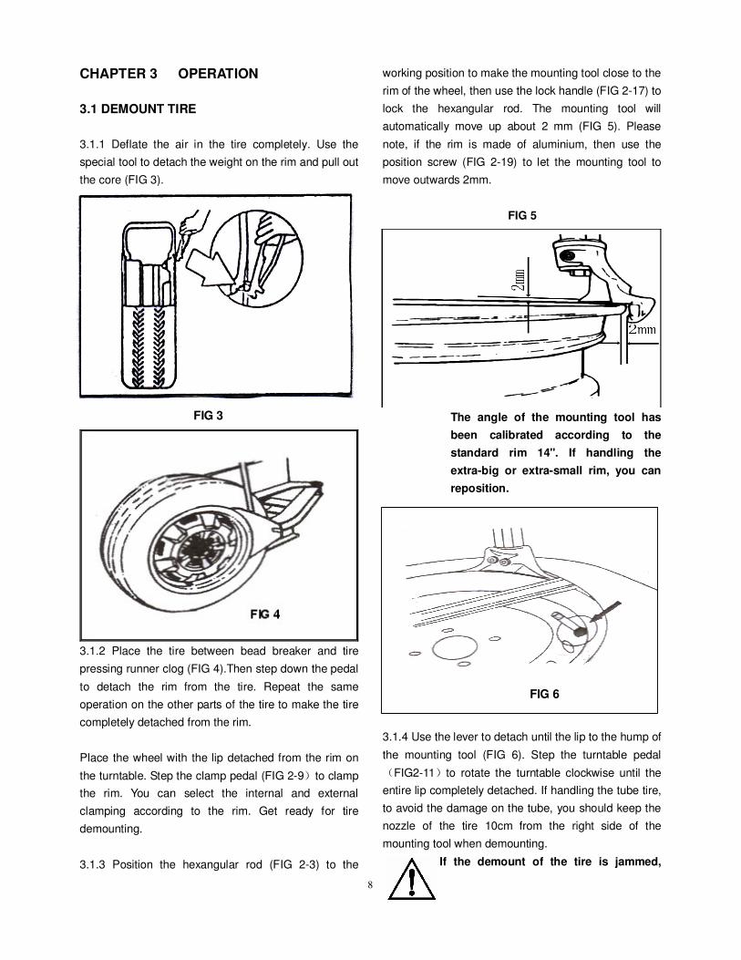
3.1.1 Deflate the air in the tire completely. Use the
special tool to detach the weight on the rim and pull out
the core (FIG 3).
FIG 3
3.1.2 Place the tire between bead breaker and tire
pressing runner clog (FIG 4).Then step down the pedal
to detach the rim from the tire. Repeat the same
operation on the other parts of the tire to make the tire
completely detached from the rim.
Place the wheel with the lip detached from the rim on
the turntable. Step the clamp pedal (FIG 2-9)to clamp
the rim. You can select the internal and external
clamping according to the rim. Get ready for tire
demounting.
3.1.3 Position the hexangular rod (FIG 2-3) to the
working position to make the mounting tool close to the
rim of the wheel, then use the lock handle (FIG 2-17) to
lock the hexangular rod. The mounting tool will
automatically move up about 2 mm (FIG 5). Please
note, if the rim is made of aluminium, then use the
position screw (FIG 2-19) to let the mounting tool to
move outwards 2mm.
FIG 5
The angle of the mounting tool has
been calibrated according to the
standard rim 14". If handling the
extra-big or extra-small rim, you can
reposition.
3.1.4 Use the lever to detach until the lip to the hump of
the mounting tool (FIG 6). Step the turntable pedal
(FIG2-11)to rotate the turntable clockwise until the
entire lip completely detached. If handling the tube tire,
to avoid the damage on the tube, you should keep the
nozzle of the tire 10cm from the right side of the
mounting tool when demounting.
If the demount of the tire is jammed,
FIG 6

9
please stop the machine immediately
and then lift up the pedal to let the
turntable rotate counter-clockwise to
remove the resistance!!!!
3.1.5 When handling the tube tire, take out the tube and
then move the lower lip upwards to the upper edge of
the rim and then repeat the above steps to detach the
other lip.
In the process of demounting tire, you
should keep your hands and the other
parts of your body from the movable
parts. Necklace, bracelet and the loose
clothing can injury personnel!!!!
3.2 MOUNT TIRE::::
Before mount tire, check if the tire and rim
are of the same dimension!!!!
3.2.1 Clean the dirt and rust on the rim and lock it on
the turntable.
3.2.2 Spread the lubrication liquid or soap liquid around
the lip. Tilt the tire against the rim and keep the front
end upwards. Press down the hexangular rod to move
the demount arm to contact with the rim and lock. The
left lip above the tail of the mounting tool and the right
lip will be positioned under the front end of the
mounting tool (FIG 7),Clockwise rotate the turntable to
guide the bottom lip into the tire detaching slot.
3.2.3 If there is tube, place it in the tire and plug the
core. And assemble the lip according to the above
mentioned steps (FIG 8).
In the process of clamping the rim, do
not reach your hands between the rim
and the clamp to avoid the damage to
the personnel.
3.3 INFLATION::::
When inflating the tire, please be carefully and obey the
operation process. Check the air route to see if the air
connection is OK. This machine is equipped with an
inflation gauge for monitoring the inflation of the tire and
the inflation pressure.
1. Loosen the tire from the turntable.
2. Connect the inflation hose with the tire valve (FIG 9).
FIG 9
3. In the process of inflation, you should repeat
Fig 7
FIG 8
10
stepping the inflation pedal to confirm the pressure
indicated on the pressure gauge not exceeds the
scope specified by the manufacturer.
4. If the inflation pressures too high, you can press
down the deflation press button on the inflation
device to reach the required air pressure.
3.4 QUICK TIRE INFLATION:
If it is tubeless tire and the sealing of the tire and the
rim is no good, the above inflation methods are no
useful. On this condition, we should operate the quick
tire inflation and then the above methods.
1. There is an inflation pedal on the right side of the
body. This pedal has 2 gears. The first gear is for
the inflation on the tire with tube.When inflation,
you can gently press the pedal for many times to
confirm the pressure display of the pressure
gauge not exceed the scope specified by the
manufacturer.
2. The second gear is the assistant inflation for the
tubeless tire. When inflation, you can step the
pedal to the floor and then loosen the pedal to
make it return to the first gear and then use the
inflation hose to inflate.
Warning !!!! Explosive !!!! When inflating,
please obey the following instructions:
� Carefully check if the tire and the rim are of the
same dimension and check the wear condition
of the tire to confirm the tire not damaged
before inflation.
� When the air pressure needed for inflation
relatively high, you can take off the tire and to
inflate under the protective cover.
� When inflating the tire, please be carefully.
Keep your hands and body away from the tire.
CHAPTER 4 MAINTENANCE AND REPAIR
Only the qualified professional personnel
can execute the maintenance. Before any
maintenance, cut off the power, and
ensure the maintenance personnel can
take charge of the power plug. Meanwhile,
cut off the air supply and pull off the quick
adaptor of supply and completely deflate
the residual air in the machine.
To correctly use the tire changer and prolong its
working life, it is necessary to periodically maintenance
and repair according to the instruction manual.
Otherwise the running and reliability of the machine will
be affected and the personnel near the machine or the
operator will be injured.
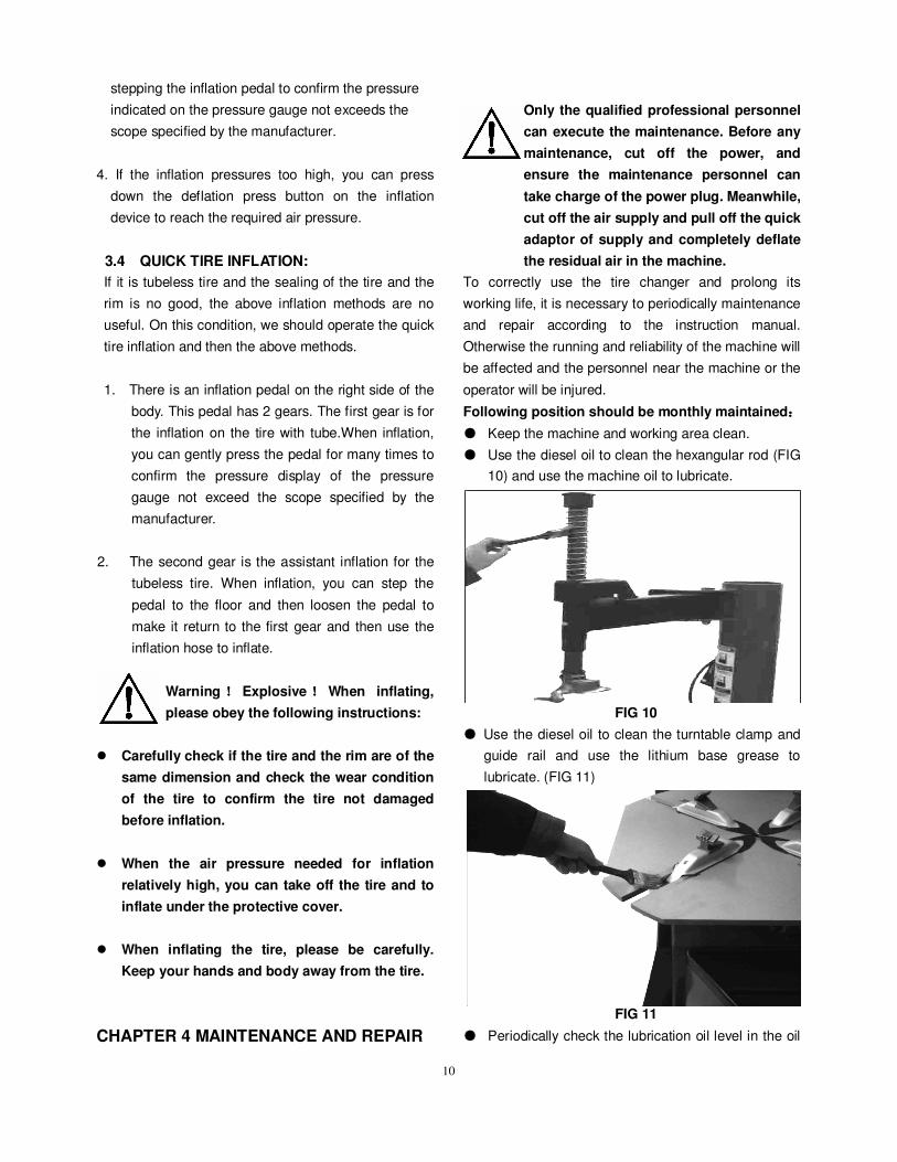
Following position should be monthly maintained::::
● Keep the machine and working area clean.
● Use the diesel oil to clean the hexangular rod (FIG
10) and use the machine oil to lubricate.
FIG 10
● Use the diesel oil to clean the turntable clamp and
guide rail and use the lithium base grease to
lubricate. (FIG 11)
FIG 11
● Periodically check the lubrication oil level in the oil
11
fog device. If the oil level lower than the oil scale,
please feed in the SAE 10W ISO 32 oil in time
(FIG 12)
FIG 12
● Drain out the water and impurity in the oil-water
separator periodically.
● Periodically check and adjust the tension of the
driven belt. Properly adjust the adjust nut in A and
B to realize the proper tension.(FIG 13)。
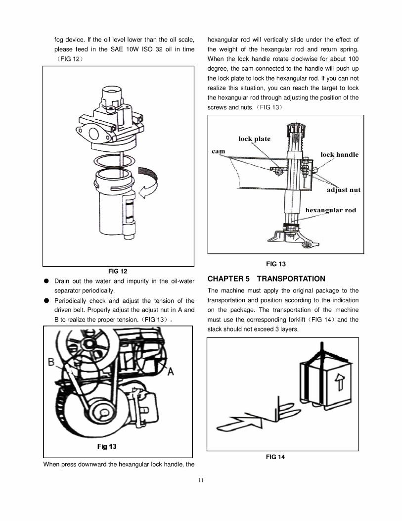
When press downward the hexangular lock handle, the
hexangular rod will vertically slide under the effect of
the weight of the hexangular rod and return spring.
When the lock handle rotate clockwise for about 100
degree, the cam connected to the handle will push up
the lock plate to lock the hexangular rod. If you can not
realize this situation, you can reach the target to lock
the hexangular rod through adjusting the position of the
screws and nuts.(FIG 13)
FIG 13
CHAPTER 5 TRANSPORTATION
The machine must apply the original package to the
transportation and position according to the indication
on the package. The transportation of the machine
must use the corresponding forklift(FIG 14)and the
stack should not exceed 3 layers.
FIG 14
12
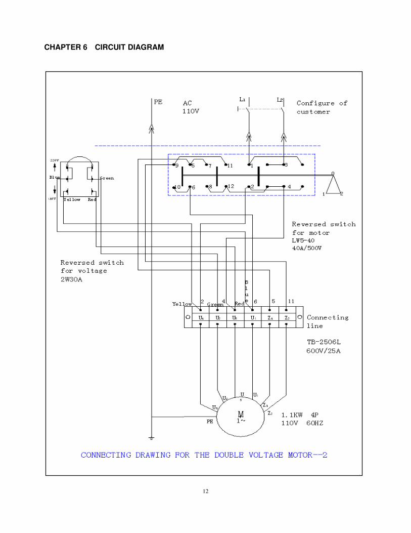
CHAPTER 6 CIRCUIT DIAGRAM

13
CHAPTER 7 TROUBLESHOOTING
Trouble
Reason
Solution
Turntable rotates in one direction. Universal switch contact burned Change Universal switch
Turntable does not rotate. Belt damage
Belt too loose
Motor or power source have problems
Universal switch contact damage
Change belt
Adjust the tension of the belt
Check motor, power source and power source
cable
Change motor
Change Universal switch
Turntable can not clamp the rim as
normal
Clamp worn
Clamp cylinder air leakage
Change clamps
Change the air leakage sealing parts
hexangular rod
cannot lock
Lock plate not in position
See Chapter 4
Chassis pedal not return. Pedal return spring damage Change torsion spring
Motor not rotate or the output
torque not enough
Drive system jam
Capacitor broken down
Voltage not enough
Short-circuit
Remove the jam
Change capacitor
Wait for the restore of the voltage
Remove
Cylinder output force not enough Air leakage
Mechanical fault
Air pressure not enough
Change sealing parts
Remove the fault
Adjust the air pressure to meet the requirement
Air leakage Air pipe damage
Pipe connect damage
Sealing end damage
Sealing glue missing
Change damaged parts
Add sealing glue