Embed Size (px)
Citation preview

Rol COOL13 6/10/13
HELICAL COOLING CHANNEL PROGRESS*
R. P. Johnson#, Muons, Inc., Batavia, IL, U.S.A.
Y. S. Derbenev, JLab, Newport News, VA, USA
K. Yonehara, Fermilab, Batavia, IL, USA (and many other SBIR-STTR collaborators)
We describe the design and construction plans for a 1-m,
20-cavity prototype Helical Cooling Channel (HCC)
segment, including the development of oxygen-doped
hydrogen-pressurized RF cavities that are loaded with
dielectric, fed by magnetrons, and operate in a
superconducting helical solenoid magnet. A 300 m long
cooling channel composed of similar segments will reduce
the 6D emittance of a muon beam by almost a factor of
one million. Please visit http://www.muonsinc.com/
1
Muons, Inc.
Overview
In 20 minutes, I will try to describe the outcome of ten years of developing new concepts for muon ionization cooling.
The ideas that are basic to the prototype being designed are new for this millennium:
Hydrogen-pressurized RF cavities,
doped with oxygen,
loaded with dielectric,
Helical Ionization Cooling theory using Siberian snake fields in
Helical Solenoid magnets, generating 6d cooling using
emittance exchange with a continuous homogeneous absorber
In the style of a patent application, I will describe the device, the features that make it work, and the experiments and numerical simulations that support the application.
Rol COOL13 6/10/13 2
Muons, Inc.
Rol COOL13 6/10/13 3
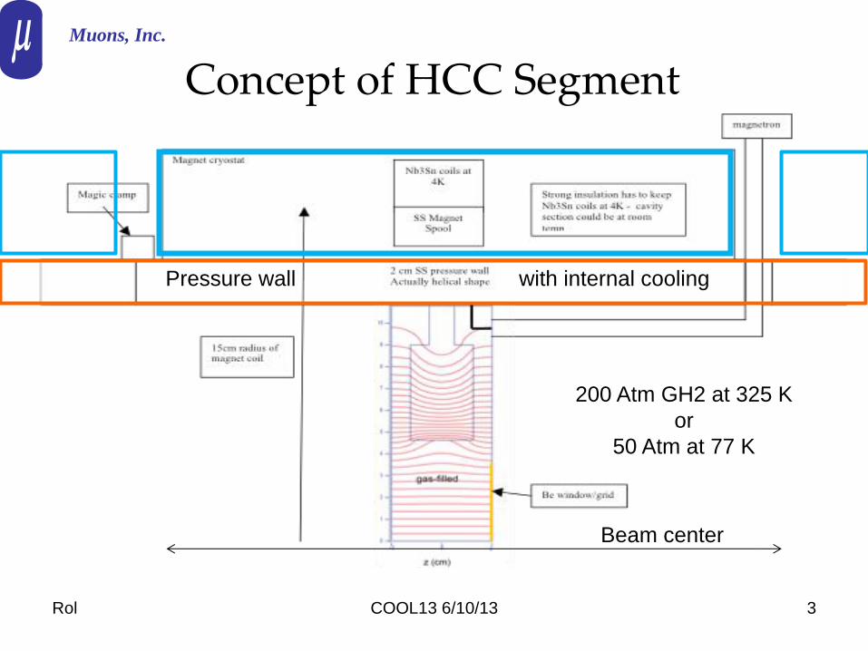
Concept of HCC Segment Muons, Inc.
Beam center
200 Atm GH2 at 325 K
or
50 Atm at 77 K
Pressure wall with internal cooling

Rol COOL13 6/10/13 4
5-cm Pillbox Cavities in HCC Muons, Inc.
End view, yellow
is beam region
Side view, green is Be grid to keep
RF in pillbox and allow GH2 to pass
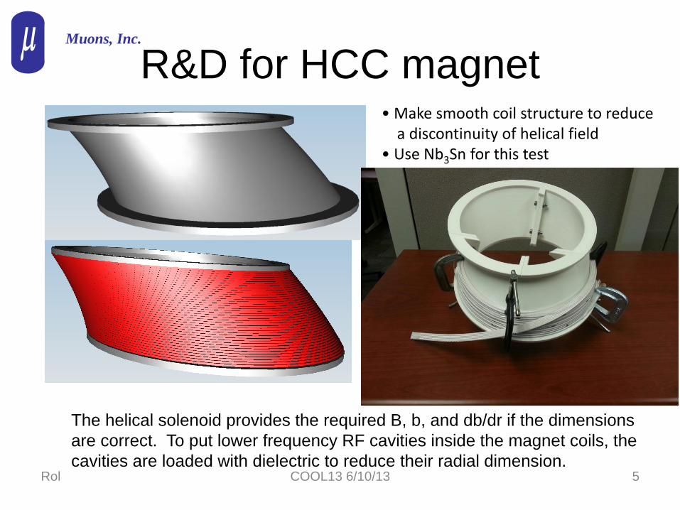
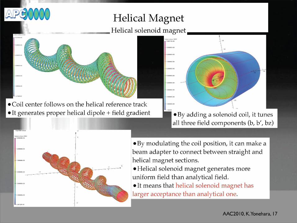
R&D for HCC magnet
Rol COOL13 6/10/13 5
• Make smooth coil structure to reduce a discontinuity of helical field • Use Nb3Sn for this test
Muons, Inc.
The helical solenoid provides the required B, b, and db/dr if the dimensions
are correct. To put lower frequency RF cavities inside the magnet coils, the
cavities are loaded with dielectric to reduce their radial dimension.
Rol COOL13 6/10/13 6
z
RFp
inp
cool out RFp p p
absp
inp
a
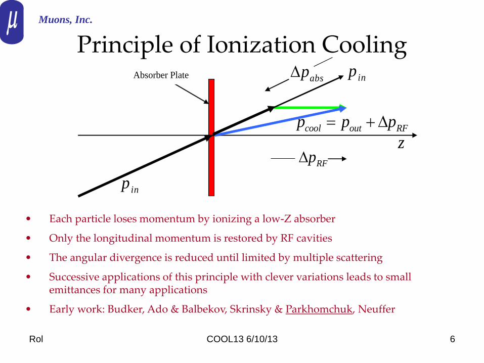
Absorber Plate
• Each particle loses momentum by ionizing a low-Z absorber
• Only the longitudinal momentum is restored by RF cavities
• The angular divergence is reduced until limited by multiple scattering
• Successive applications of this principle with clever variations leads to small emittances for many applications
• Early work: Budker, Ado & Balbekov, Skrinsky & Parkhomchuk, Neuffer
Principle of Ionization Cooling Muons, Inc.

Rol COOL13 6/10/13 7
Transverse Emittance IC The equation describing the rate of cooling is a balance
between cooling (first term) and heating (second term):
Here n is the normalized emittance, Eµ is the muon energy in GeV, dEµ/ds and X0 are the energy loss and radiation length of the absorber medium, is the transverse beta-function of the magnetic channel, and is the particle velocity.
2
2 3
0
(0.014)1 1
2
n ndEd
ds ds E E m X
Muons, Inc.
Bethe-Bloch Moliere (with low Z mods)
Rol COOL13 6/10/13 8
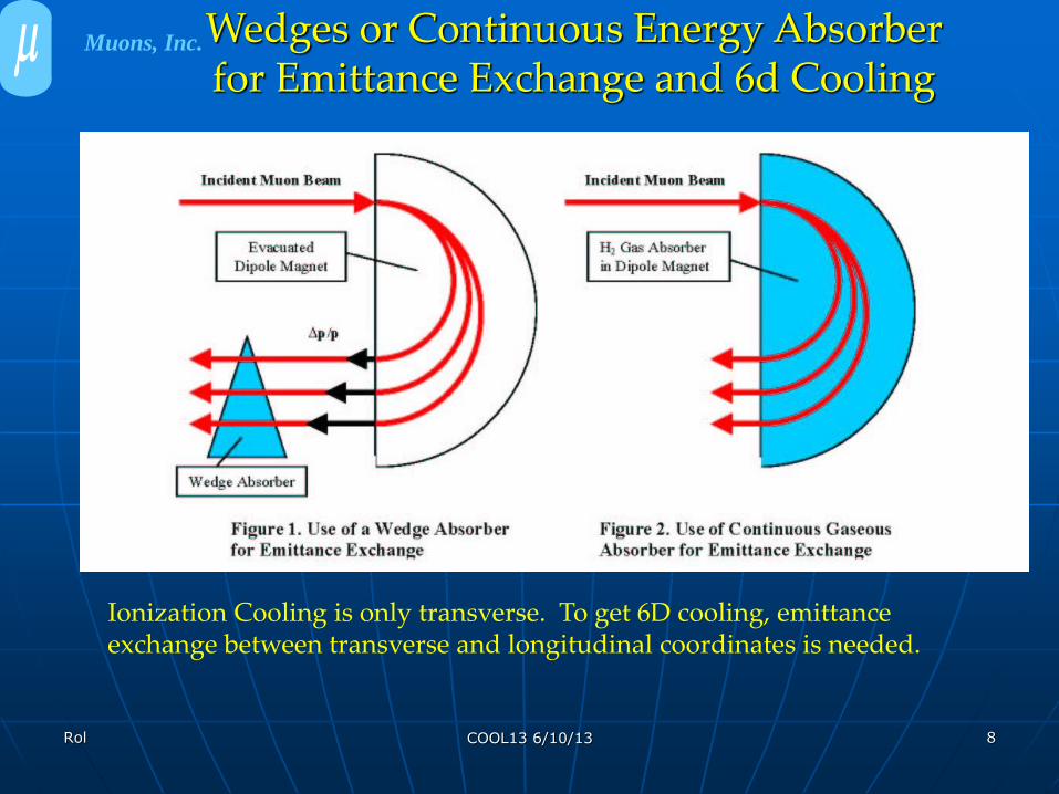
Ionization Cooling is only transverse. To get 6D cooling, emittance exchange between transverse and longitudinal coordinates is needed.
Wedges or Continuous Energy Absorber for Emittance Exchange and 6d Cooling
Muons, Inc.
Rol COOL13 6/10/13 9
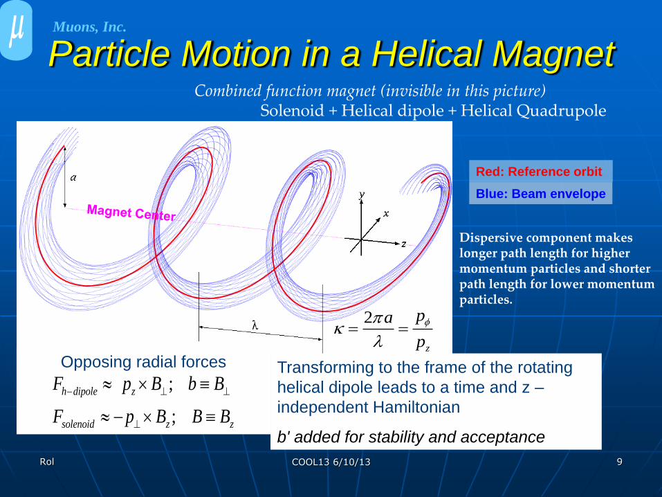
Particle Motion in a Helical Magnet
Blue: Beam envelope
2
z
pa
p
Red: Reference orbit
Combined function magnet (invisible in this picture) Solenoid + Helical dipole + Helical Quadrupole
Dispersive component makes longer path length for higher momentum particles and shorter path length for lower momentum particles.
Muons, Inc.
Opposing radial forces
;
;
h dipole z
solenoid z z
F p B b B
F p B B B
Transforming to the frame of the rotating
helical dipole leads to a time and z –
independent Hamiltonian
b' added for stability and acceptance

Rol COOL13 6/10/13 10
Some Important Relationships
2
2
11
3
ckq
k
21ck B p
2
2
1ˆ 2p da
Da dp
0q
2 2 2
3 2 2
1 1 1ˆ1
dD
d
2
2ˆ
1D
2
1
transition
2 21 1( )p a B b
k
2k ka Hamiltonian Solution
Equal cooling
decrements
Longitudinal
cooling only
~Momentum slip
factor ~
Muons, Inc.
Hardware Development
• Helical Solenoid invention to get HCC fields
– 4-coil NbTi HS model tested (1st 6d HCC segment)
– 6-coil YBCO HS model tested (last 6d HCC segment)
• High Pressure H2 Cavity development
– Test cell shows no HV max dependence on external B
– First beam tests show agreement with models
• No RF breakdown
• Ionization electrons move far enough to heat H2 – reduce Q
• Mitigated with 0.01% SF6 dopant
• Oxygen shown to be a good dopant with less corrosion Rol COOL13 6/10/13 11
Muons, Inc.
Rol COOL13 6/10/13 12
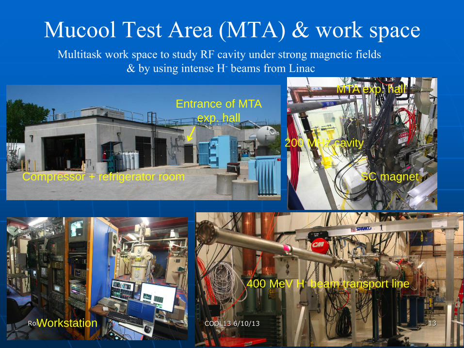
Mucool Test Area (MTA) & work space Multitask work space to study RF cavity under strong magnetic fields
& by using intense H- beams from Linac
Compressor + refrigerator room
Entrance of MTA
exp. hall
MTA exp. hall
SC magnet
200 MHz cavity
Workstation
400 MeV H- beam transport line
Rol 13 COOL13 6/10/13
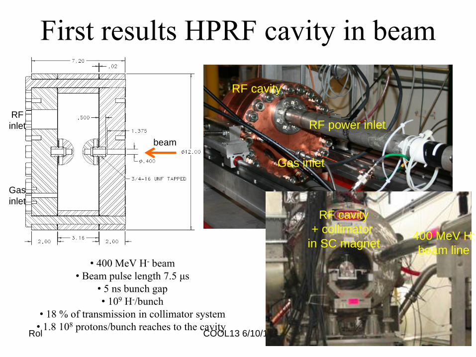
First results HPRF cavity in beam
Rol COOL13 6/10/13 14
beam
Gas
inlet
RF
inlet
• 400 MeV H- beam
• Beam pulse length 7.5 μs
• 5 ns bunch gap
• 109 H-/bunch
• 18 % of transmission in collimator system
• 1.8 108 protons/bunch reaches to the cavity
RF power inlet
Gas inlet
RF cavity
RF cavity
+ collimator
in SC magnet 400 MeV H-
beam line
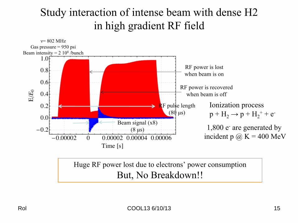
Study interaction of intense beam with dense H2
in high gradient RF field
Beam signal (x8)
(8 μs)
RF power is lost
when beam is on
RF power is recovered
when beam is off
RF pulse length
(80 μs) p + H2 → p + H2+ + e-
Ionization process
1,800 e- are generated by
incident p @ K = 400 MeV
Huge RF power lost due to electrons’ power consumption
But, No Breakdown!!
ν= 802 MHz
Gas pressure = 950 psi
Beam intensity = 2 108 /bunch
Rol COOL13 6/10/13 15

Electronegative gas H2+SF6 (0.01%) gas
SF6 removes a residual electron
Great improvement!
Beam signal (x8)
(8 μs)
ν= 802 MHz
H2 + SF6 (0.01 % condensation)
Gas pressure = 950 psi
Beam intensity = 2 108 /bunch
RF pickup voltage
Rol COOL13 6/10/13 16
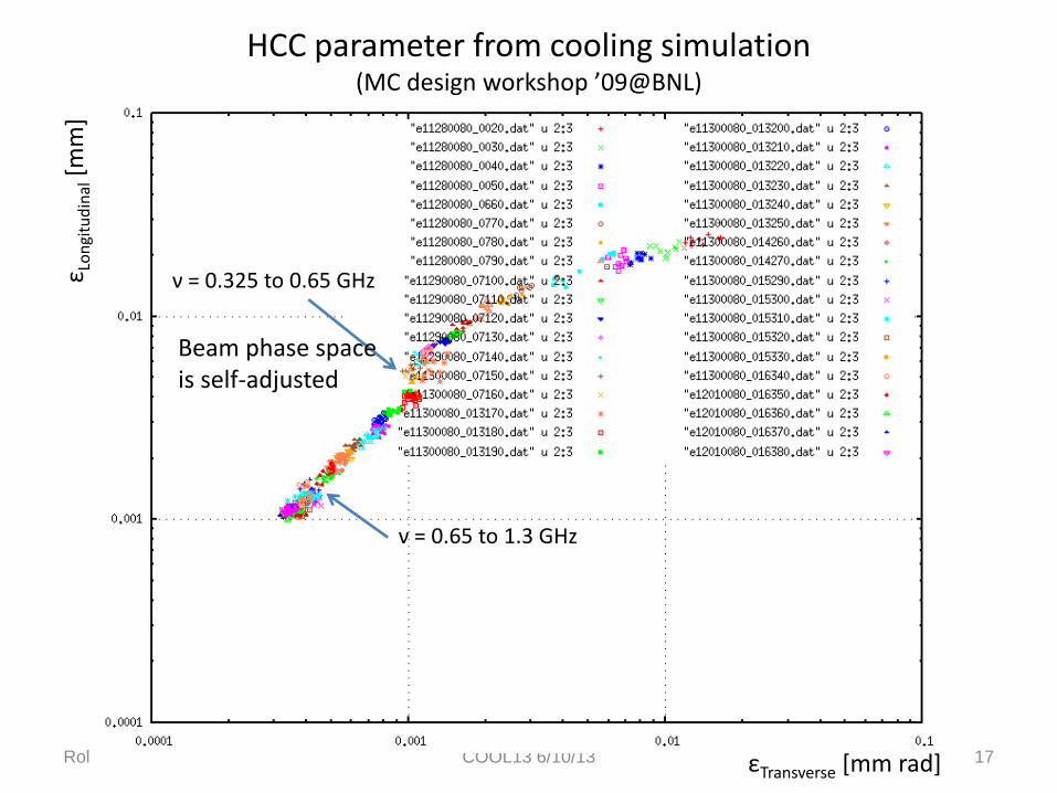
HCC parameter from cooling simulation (MC design workshop ’09@BNL)
Rol COOL13 6/10/13 17
ε Lon
gitu
din
al [
mm
]
εTransverse [mm rad]
ν = 0.325 to 0.65 GHz
ν = 0.65 to 1.3 GHz
Beam phase space is self-adjusted
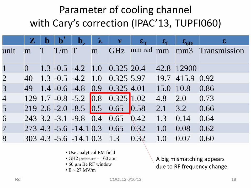
Parameter of cooling channel with Cary’s correction (IPAC’13, TUPFI060)
Rol COOL13 6/10/13 18
Z b b’ bz λ ν εT εL ε6D ε
unit m T T/m T m GHz mm rad mm mm3 Transmission
1 0 1.3 -0.5 -4.2 1.0 0.325 20.4 42.8 12900
2 40 1.3 -0.5 -4.2 1.0 0.325 5.97 19.7 415.9 0.92
3 49 1.4 -0.6 -4.8 0.9 0.325 4.01 15.0 10.8 0.86
4 129 1.7 -0.8 -5.2 0.8 0.325 1.02 4.8 2.0 0.73
5 219 2.6 -2.0 -8.5 0.5 0.65 0.58 2.1 3.2 0.66
6 243 3.2 -3.1 -9.8 0.4 0.65 0.42 1.3 0.14 0.64
7 273 4.3 -5.6 -14.1 0.3 0.65 0.32 1.0 0.08 0.62
8 303 4.3 -5.6 -14.1 0.3 1.3 0.32 1.0 0.07 0.60
• Use analytical EM field
• GH2 pressure = 160 atm
• 60 μm Be RF window
• E ~ 27 MV/m
A big mismatching appears due to RF frequency change
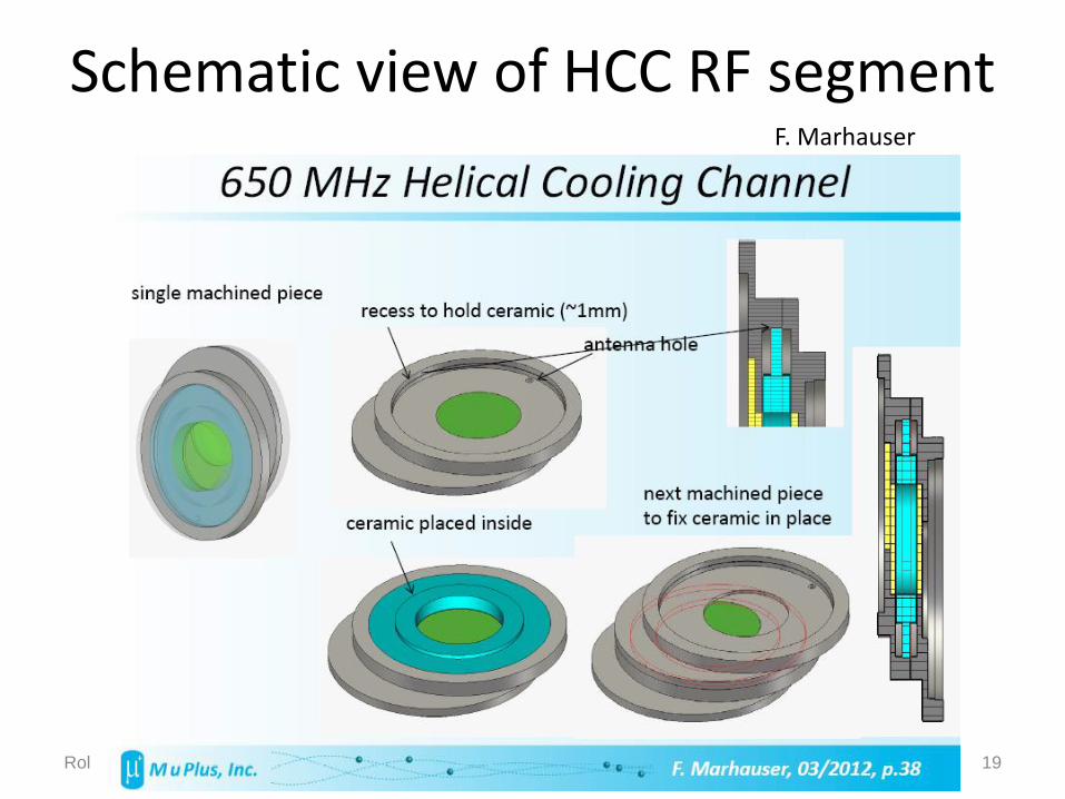
Schematic view of HCC RF segment
Rol COOL13 6/10/13 19
F. Marhauser

Recent result of dielectric loaded gas-filled RF cavity
Rol COOL13 6/10/13 20
Old cavity test
RF gradient at highest point (convex of electrode)
RF gradient on ceramic rod
• Open blue circle: peak E at electrode Close blue circle: surface E • Compare old result (orange) • At p < 200 psi, observed peak E (open circle) shows gas BD • At p > 200 psi, observed peak E shows a plateau • This limit seems to be determined by the surface E since it is close to the dielectric strength
L. Nash et al., IPAC’13 TUPFI068

Rol COOL13 6/10/13 21
High pressure gas suppresses breakdown even when
alumina dielectric fails at 12 to 14 MV/m in test cell
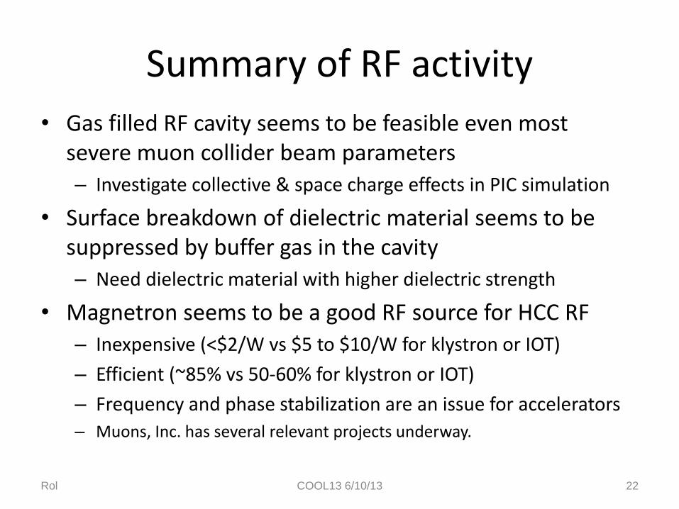
Summary of RF activity
• Gas filled RF cavity seems to be feasible even most severe muon collider beam parameters
– Investigate collective & space charge effects in PIC simulation
• Surface breakdown of dielectric material seems to be suppressed by buffer gas in the cavity
– Need dielectric material with higher dielectric strength
• Magnetron seems to be a good RF source for HCC RF
– Inexpensive (<$2/W vs $5 to $10/W for klystron or IOT)
– Efficient (~85% vs 50-60% for klystron or IOT)
– Frequency and phase stabilization are an issue for accelerators
– Muons, Inc. has several relevant projects underway.
Rol COOL13 6/10/13 22

In next 18 months • Construct part of a Nb3Sn HCC segment
• Continue studies of gas filled RF cavities
– Find and test better dielectric materials
– Investigate possible 77 K operation
– Develop magnetron RF source
• Mechanical design of 1-m HCC segment
– Make everything fit and easy to build and maintain
– Cryostat design with constraints
– GH2 containment and pressure system code requirements
• Simulations and calculations
– Optimize design for 6D cooling demo, study tolerances,…
Rol COOL13 6/10/13 23