Embed Size (px)
Citation preview
w w w . i p e x n a . c o m
Municipal Product Catalogue
I S S U E D A T E : N O V E M B E R 2 0 1 7
• Pressure Piping Systems
• Water Service Systems
• Sewer Piping Systems
• Specialty Municipal Products
We build tough products for tough environments.®
As a leader in thermoplastic piping systems for over 50 years, IPEX Inc. provides proven products that have withstood the rigours of time – from large diameter transmission pipelines to 3/4” house connections.
Our PVC water and sewer systems do not corrode so they maintain the strength and flexibility required to handle soil movement, high traffic loads and deep burial applications. At IPEX, we ensure our systems outperform our competitors with:
• Quality assurance testing that exceeds standards
• Custom-designed PVC compounds
• Third-party certification of pipe and fittings from organizationssuch as Canadian Standards Association, Factory Mutual, Underwriter’s Laboratories and NSF
2002
Committedto EXCELLENCE

PRESSURE PIPING SYSTEMS
Blue Brute Pipe
Blue Brute Fittings
Bionax PVCO Pipe
Bionax SR Pipe
IPEX Centurion
IPEX Fusible
TerraBrute CR
CycleTough
WATER SERVICE SYSTEMS
Blue904
Q-Line
Gold 901
Philmac 3G Compression Fittings
SEWER PIPING SYSTEMS
Ring-Tite / Enviro-Tite
Ultra-Rib
Ultra-X2
NovaForm PVC Liner
Solvent Weld Sewer Fittings
SPECIALTY PRODUCTS
Vortex Flow Inserts
LifeSaver Manhole & Catchbasin Adjustment Units
Storm Sewer Inlet Controls
EASY SPECIFICATIONS
10
21
82
01
33
47
79
Contents
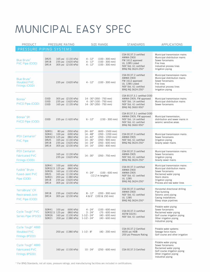
MUNICIPAL EASY SPECPRODUCT PRESSURE RATING SIZE RANGE STANDARDS APPLICATIONS
PRESSURE P I P ING SYSTEMS
Blue Brute® PVC Pipe (CIOD)
DR25 165 psi (1130 kPa)DR18 235 psi (1620 kPa)DR14 305 psi (2100 kPa)
4 - 12" (100 - 300 mm) 4 - 12" (100 - 300 mm) 4 - 12" (100 - 300 mm)
CSA B137.3 certifi edAWWA C900FM 1612 approvedUL 1285 ListedNSF Std. 61 certifi edBNQ NQ 3624-250*
Municipal transmission mainsMunicipal distribution mainsSewer forcemainsFire linesIndustrial process linesIrrigation piping
Blue Brute®
Moulded PVC Fittings (CIOD)
235 psi (1620 kPa) 4 - 12" (100 - 300 mm)
CSA B137.2 certifi edAWWA C900FM 1612 approvedUL 1285 ListedNSF Std. 61 certifi edBNQ NQ 3624-250*
Municipal transmission mainsMunicipal distribution mainsSewer forcemainsFire linesIndustrial process linesIrrigation piping
Bionax®
PVCO Pipe (CIOD)
CIOD 305 psi (2100 kPa)CIOD 235 psi (1620 kPa)CIOD 165 psi (1135 kPa)
14 - 30" (350 - 750 mm) 4 - 30" (100 - 750 mm) 14 - 30" (350 - 750 mm)
CSA B137.3.1 certifi ed CIODAWWA C909, FM approvedNSF Std. 14 certifi edNSF Std. 61 certifi edBNQ NQ 3660-950*
Municipal transmission mainsMunicipal distribution mainsSewer forcemains
Bionax® SR
PVCO Pipe (CIOD)CIOD 235 psi (1 620 kPa) 6 - 12" (150 - 300 mm)
CSA B137.3.1 certifi ed CIODAWWA C909, FM approvedNSF Std. 14 certifi edNSF Std. 61 certifi edBNQ NQ 3660-950*
Municipal transmission, distribution and sewer mains in seismic sensitive areas
IPEX Centurion®
PVC Pipe
SDR51 80 psi (550 kPa)SDR41 100 psi (690 kPa)SDR32.5 125 psi (860 kPa)DR25 165 psi (1130 kPa)DR18 235 psi (1620 kPa)DR14 305 psi (2100 kPa)
24 - 60" (600 - 1500 mm) 14 - 48" (350 - 1200 mm) 14 - 42" (350 - 1050 mm) 14 - 36" (350 - 900 mm) 14 - 24" (350 - 600 mm) 14 - 16" (350 - 400 mm)
CSA B137.3 certifi edAWWA C905NSF Std. 61 certifi edBNQ NQ 3624-250*
Municipal transmission mainsSewer forcemainsIrrigation pipingGravity sewer mains
IPEX Centurion
Fabricated PVC
Fittings (CIOD)
165 psi (1130 kPa) 235 psi (1620 kPa)
14 - 30" (350 - 750 mm)
CSA B137.3 certifi edAWWA C905NSF Std. 61 certifi edBNQ NQ 3624-250*
Municipal transmission mainsSewer forcemainsIrrigation pipingGravity sewer mains
FusibleTM Brute
Fused-Joint PVC
Pipe (CIOD)
SDR41 100 psi (690 kPa)SDR32.5 125 psi (860 kPa)SDR26 160 psi (1100 kPa)DR25 165 psi (1130 kPa)SDR21 200 psi (1380 kPa)DR18 235 psi (1620 kPa)DR14 305 psi (2100 kPa)
4 - 24" (100 - 600 mm)(12.2 m lengths)
CSA B137.3 certifi edAWWA C900AWWA C905NSF Std. 61 certifi edUL 1285BNQ NQ 3624-250*
Municipal transmission mainsMunicipal distribution mainsSewer forcemainsReclaimed water pipingStorm drainsIrrigation pipingProcess and raw water lines
TerraBrute® CR
Restrained-Joint
PVC Pipe (CIOD)
DR18 235 psi (1620 kPa)DR14 305 psi (2100 kPa)
8 - 12" (200 - 300 mm) 4 & 6" (100 & 150 mm)
CSA B137.3 certifi edAWWA C900NSF Std. 61 certifi edUL 1285BNQ NQ 3624-250*
Horizontal directional drillingPipe burstingSeismic zone pipingCasing installationsSteep slope pipelines
Cycle Tough® PVC
Series Pipe (IPSOD)
SDR41 100 psi (690 kPa)SDR32.5 125 psi (860 kPa)SDR26 160 psi (1100 kPa)SDR21 200 psi (1380 kPa)
4 - 24" (100 - 600 mm) 3 - 24" (75 - 600 mm) 1-1/2 - 24" (40 - 600 mm) 1-1/2 - 24" (40 - 600 mm)
CSA B137.3 certifi edASTM D2241NSF Std. 61 certifi ed
Potable water pipingSewer forcemainsReclaimed water pipingGolf course irrigation pipingOther irrigation pipingIndustrial piping
Cycle Tough® 4000
Moulded PVC
Fittings (IPSOD)
200 psi (1380 kPa) 1-1/2 - 8" (40 - 200 mm)CSA B137.2 Certifi ed4000 psi HDB200 psi Pressure Rating
Potable water systemsSewage force mainsGolf course and other irrigation
Cycle Tough® 4000
Fabricated PVC
Fittings (IPSOD)
160 psi (1100 kPa) 10 - 24" (250 - 600 mm) CSA B137.3 Certifi ed
Potable water pipingSewer forcemainsReclaimed water pipingGolf course irrigation pipingOther irrigation pipingIndustrial piping
* For BNQ Standards, not all sizes, pressure ratings, and manufacturing facilities are included in certifi cations.

PRODUCT PRESSURE RATING SIZE RANGE STANDARDS APPLICATIONS
WATER S ERV ICE SYSTEMS
Blue904TM
SDR9 PEX Service Tubing (CTS)
160 psi @ 73.4ºF (1100 kPa @ 23ºC)100 psi @ 180ºF (690 kPa @ 82ºC)80 psi @ 200ºF
(550 kPa @ 93ºC)
3/4 - 2" (20 - 50 mm)
CSA B137.5 certifi edAWWA C904ASTM F876, ASTM F877NSF Std. 14 certifi edNSF Std. 61 certifi ed
Municipal water service
Q-LineTM PE-AL-PE Service Tubing
200 psi @ 73.4ºF (1380 kPa @ 23ºC)100 psi @ 180ºF (690 kPa @ 82ºC)
3/4 & 1" (20 & 25 mm)
CSA B137.9 certifi edAWWA C903ASTM F1282NSF Std. 14 certifi edNSF Std. 61 certifi ed
Municipal water serviceReclaimed water
Gold 901TM
PE Service Tubing
(CTS)
200 psi @ 73ºF (1380 kPa @ 23ºC)
3/4 - 2" (20 - 50 mm) CSA B137.1 certifi edNSF Std. 61 certifi ed
Municipal water service
S E W E R P I P I N G S Y S T E M S
Ring-Tite®
PVC Sewer Pipe
(PSM)
DR35 4 - 60" (100 - 1500 mm)
CSA B182.2 certifi edASTM D3034ASTM F679ASHTO M278BNQ NQ 3624-130 & 3624-135*
Sanitary sewerStorm sewerIndustrial effl uent
Enviro-Tite®
PVC Sewer Pipe
(PSM)
DR35 4 - 15" (100 - 375 mm)CSA B182.2 certifi edASTM D1760BNQ NQ 3624-130 & 3624-135*
Sanitary sewerStorm sewerIndustrial effl uent
Ring-Tite®
Heavy Wall PVC
Sewer Pipe (PSM)
DR28 4 - 6" (100 - 150 mm) Certifi ed to CSA B182.2BNQ NQ 3624-130 & 3624-135*
Sanitary sewer lateralsStorm sewer lateralsIndustrial effl uent
Enviro-Tite®
PVC Sewer Pipe
(PSM)
DR28 4 - 6" (100 - 150 mm) Certifi ed to CSA B182.2BNQ NQ 3624-130 & 3624-135*
Sanitary sewer lateralsStorm sewer lateralsIndustrial effl uent
Ring-Tite®
Gasketed Sewer
Fittings (PSM)
4 - 42" (100 - 1050 mm)CSA B182.2 certifi edASTM D3034ASTM F679
Sanitary sewerStorm sewerIndustrial effl uent
IPEX Centurion®
PVC Pipe (CIOD) DR51DR41 24 - 48" (600 - 1200 mm)
CSA B137.3 certifi edAWWA C905BNQ NQ 3624-250*
Sanitary sewerStorm sewerIndustrial effl uent
Ultra-Rib®
PVC Sewer Pipe
(Open profile OD)
8 - 24" (200 - 600 mm)CSA B182.4 certifi edASTM F794ASHTO M304
Sanitary sewerStorm sewerHighway / culvert
Ultra-Rib®
PVC Sewer Fittings
(Open profile OD)
8 - 24" (200 - 600 mm) CSA B182.4 certifi edASTM F794
Sanitary sewerStorm sewerHighway / culvert
Ultra-X2®
PVC Sewer Fittings
(Open profile OD)
30 & 36" (750 & 900mm) CSA B182.4ASTM F794
Storm sewerHighway / culvert
NovaFormTM
PVC Liner 6 - 30" (150 - 750 mm) ASTM F1504
Sewer RehabilitationCulvert Rehabilition
* For BNQ Standards, not all sizes, pressure ratings, and manufacturing facilities are included in certifi cations.

Why swim with all the other fish?
✓ Molecularly Enhanced
✓ 2X Stronger
✓ 3X Tougher
✓ 2X More Flexible
✓ Code Compliant
✓ Available in CIOD & IPS sizes 4” to 24”
✓ Achieves higher fl ow rates
✓ Connects directly to existing PVC systems for material consistency
✓ Use standard CIOD or IPS fi ttings
✓ Corrosion Resistant
✓ Lightweight & Flexible
✓ Jobsite Safe
✓ Fewer Connections
IPEX Municipal Water Systems...innovation at its best!
FPVCPressure Pipe
pvcoPressure Pipe
pex water service tubing
PRESSURE PIPE & FITTINGS
Blue Brute Piping Systems 6
Blue Brute Fitting Systems 10
Bionax PVCO Pressure Piping Systems 14
IPEX Centurion Piping Systems 16
IPEX Fusible 24
TerraBrute CR 26
CycleTough Piping Systems 30
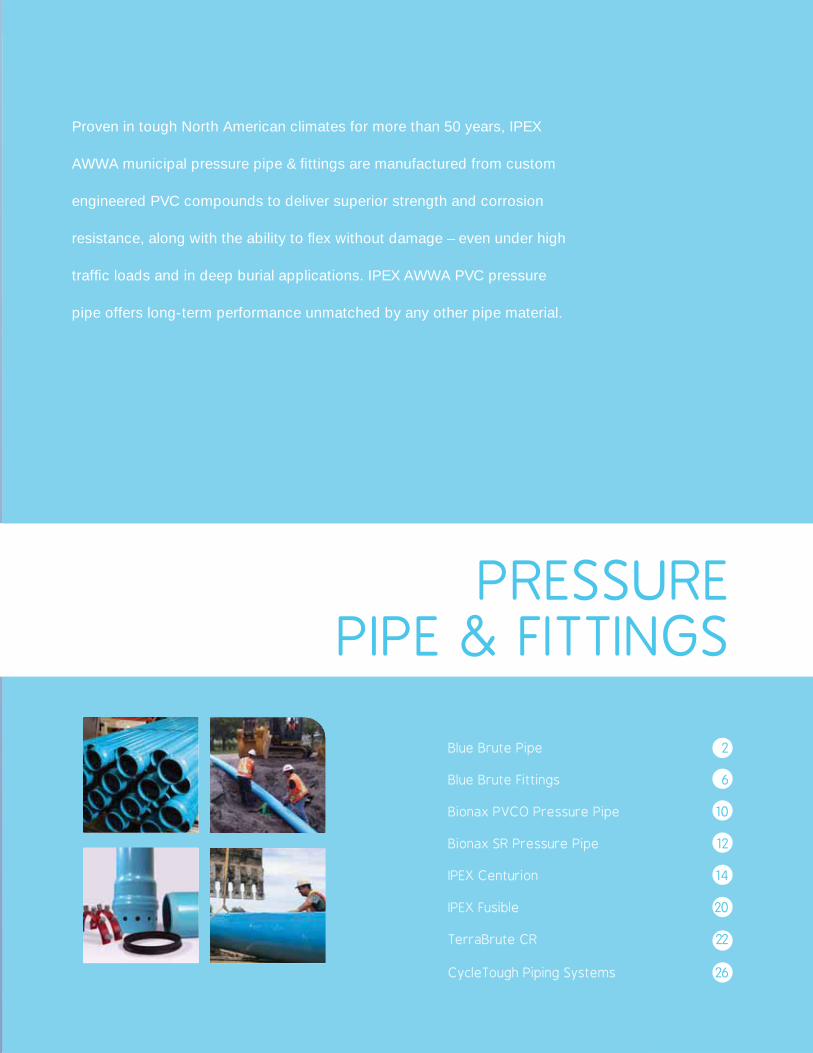
Proven in tough North American climates for more than 50 years, IPEX
AWWA municipal pressure pipe & fi ttings are manufactured from custom
engineered PVC compounds to deliver superior strength and corrosion
resistance, along with the ability to fl ex without damage – even under high
traffi c loads and in deep burial applications. IPEX AWWA PVC pressure
pipe offers long-term performance unmatched by any other pipe material.
PRESSUREPIPE & FITTINGS
Blue Brute Pipe 2
Blue Brute Fittings 6
Bionax PVCO Pressure Pipe 10
Bionax SR Pressure Pipe 12
IPEX Centurion 14
IPEX Fusible 20
TerraBrute CR 22
CycleTough Piping Systems 26

ADVANTAGES
Corrosion-Proof PerformanceIPEX Blue Brute systems are immune to corrosion from aggressive soils and galvanic action.
Superior HydraulicsThe glass-like fi nish of PVC reduces friction losses and eliminates the tuberculation common in iron pipes. As a result, pumping costs are reduced and water quality is maintained.
Cast-Iron Outside Diameter (CIOD)Blue Brute systems are manufactured with a cast-iron outside diameter (CIOD). This is compatible with waterworks valves, appurtenances and restrainers.
Bottle-tight Joints, Removable GasketsIPEX’s patented gasket system not only withstands many times the rated system pressure, but also withstands full vacuum pressures. The removable gasket system allows special oil-resistant (nitrile) gaskets to be easily installed when working in contaminated soils.
Third-party Certifi cationAll IPEX municipal systems are third-party certifi ed as applicable. In addition, IPEX Blue Brute systems have Factory Mutual approval and Underwriter’sLaboratories (ULI andULC) listings.
1
2
3
4
5
BLUE BRUTE PIPE 4” - 12” (100mm - 300mm)
2
BL
UE
B
RU
TE
P
IPE
• Municipal Water Systems
• Fire Lines
• Industrial Lines
• Forcemains
• Irrigation Lines
APPLICATIONS
STANDARDS
Designed for municipal water applications, Blue Brute AWWA C900 pressure pipe delivers superior strength with corrosion-resistant performance and the ability to fl ex without damage. Made with a high-strength, high-impact PVC compound, Blue Brute pipes perform even under high traffi c loads and deep burial conditions.
Manufactured with cast-iron outside diameters, Blue Brute is compatible with existing infrastructure of older iron pipes with no special transition fi ttings required. Blue Brute pressure pipe is hydrostatically proof tested totwo times its pressure class/rating ensuring the integrity of every length of pipe that goes into the ground.
B137.3 3624-250
NSF-61
i DID YOU KNOW?Each piece of Blue Brute ishydrostatically tested to 2 timesits pressure class, ensuringexcellent performancein the field.
1
43
2
3
BL
UE
B
RU
TE
P
IPE
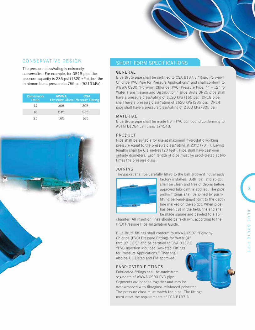
CONSERVATIVE DESIGN
The pressure class/rating is extremely conservative. For example, for DR18 pipe the pressure capacity is 235 psi (1620 kPa), but the minimum burst pressure is 755 psi (5210 kPa).
DimensionRatio
AWWA Pressure Class
CSAPressure Rating
14 305 305
18 235 235
25 165 165
SHORT FORM SPECIFICATIONS
GENERALBlue Brute pipe shall be certifi ed to CSA B137.3 “Rigid Polyvinyl Chloride PVC Pipe for Pressure Applications” and shall conform to AWWA C900 “Polyvinyl Chloride (PVC) Pressure Pipe, 4” – 12” for Water Transmission and Distribution.” Blue Brute DR25 pipe shall have a pressure class/rating of 1120 kPa (165 psi). DR18 pipe shall have a pressure class/rating of 1620 kPa (235 psi). DR14 pipe shall have a pressure class/rating of 2100 kPa (305 psi).
MATERIALBlue Brute pipe shall be made from PVC compound conforming to ASTM D1784 cell class 12454B.
PRODUCTPipe shall be suitable for use at maximum hydrostatic working pressure equal to the pressure class/rating at 23°C (73°F). Laying lengths shall be 6.1 metres (20 feet). Pipe shall have cast-iron outside diameters. Each length of pipe must be proof-tested at two times the pressure class.
JOININGThe gasket shall be carefully fi tted to the bell groove if not already
factory installed. Both bell and spigot shall be clean and free of debris before approved lubricant is applied. The pipe and/or fi ttings shall be joined by push-fi tting bell-and-spigot joint to the depth line marked on the spigot. When pipe has been cut in the fi eld, the end shall be made square and beveled to a 15º
chamfer. All insertion lines should be re-drawn, according to the IPEX Pressure Pipe Installation Guide.
Blue Brute fi ttings shall conform to AWWA C907 “Polyvinyl Chloride (PVC) Pressure Fittings for Water (4” through 12”)” and be certifi ed to CSA B137.2 “PVC Injection Moulded Gasketed Fittings for Pressure Applications.” They shall also be UL Listed and FM approved.
FABRICATED FITTINGSFabricated fi ttings shall be made from segments of AWWA C900 PVC pipe. Segments are bonded together and may be over-wrapped with fi breglass-reinforced polyester. The pressure class must match the pipe. The fi ttings must meet the requirements of CSA B137.3.

BL
UE
B
RU
TE
P
IPE
4
PRODUCT SELECTION CHARTLength: 6.1 metres | Colour: Blue
Size ProductCode
Avg. ID Min. Wall Thickness Avg. OD
in mm in mm in mm in mm
Class/Rating 165CIOD DR 25
4 100 070104 4.42 112 0.192 5 4.80 122
6 150 070106 6.35 161 0.276 7 6.90 175
8 200 070108 8.33 212 0.362 9 9.05 230
10 250 070110 10.21 260 0.444 11 11.10 282
12 300 070112 12.15 309 0.527 13 13.20 335
Class/Rating 235CIOD DR 18
4 100 070514 4.27 108 0.267 7 4.80 122
6 150 070516 6.13 155 0.383 10 6.90 175
8 200 070518 8.05 204 0.502 13 9.05 230
10 250 070520 9.87 250 0.616 16 11.10 282
12 300 070522 11.73 297 0.733 19 13.20 335
Class/Rating 305CIOD DR 14
4 100 070414 4.11 104 0.343 9 4.80 122
6 150 070416 5.91 149 0.493 13 6.90 175
8 200 070418 7.76 198 0.646 16 9.05 230
10 250 070420 9.51 242 0.793 20 11.10 282
12 300 070422 11.31 287 0.943 24 13.2 335
Capped PVC Pressure Pipe

IPEX TECHNICAL MANUALS available at www.ipexna.com
Obtaining the most up-to-date
technical information has never been easier
with our innovative ON-LINE MANUALS
Visit www.ipexna.com & check it out!
WHAT YOU CAN DO
Zoom to specifi c paragraph or chart for easy reading
Search documentfor key words
Save and email clippingsfor ultimate convenience
Download as PDFs
EnvironmentallyFriendly!
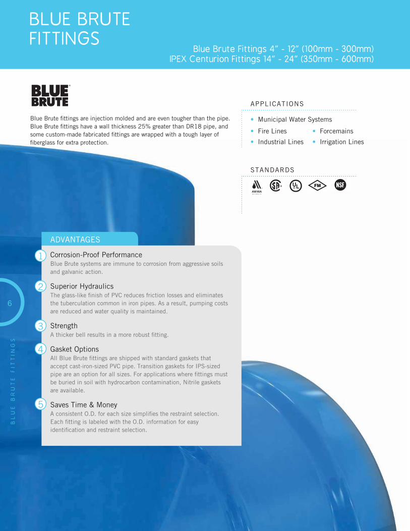
BLUE BRUTE FITTINGS
Blue Brute Fittings 4” - 12” (100mm - 300mm)IPEX Centurion Fittings 14” - 24” (350mm - 600mm)
6
BL
UE
B
RU
TE
F
ITT
ING
S
APPLICATIONS
STANDARDS
Blue Brute fi ttings are injection molded and are even tougher than the pipe. Blue Brute fi ttings have a wall thickness 25% greater than DR18 pipe, and some custom-made fabricated fi ttings are wrapped with a tough layer of fi berglass for extra protection.
ADVANTAGES
Corrosion-Proof PerformanceBlue Brute systems are immune to corrosion from aggressive soils and galvanic action.
Superior HydraulicsThe glass-like fi nish of PVC reduces friction losses and eliminates the tuberculation common in iron pipes. As a result, pumping costs are reduced and water quality is maintained.
StrengthA thicker bell results in a more robust fi tting.
Gasket OptionsAll Blue Brute fi ttings are shipped with standard gaskets that accept cast-iron-sized PVC pipe. Transition gaskets for IPS-sized pipe are an option for all sizes. For applications where fi ttings must be buried in soil with hydrocarbon contamination, Nitrile gaskets are available.
Saves Time & MoneyA consistent O.D. for each size simplifi es the restraint selection. Each fi tting is labeled with the O.D. information for easy identifi cation and restraint selection.
1
2
3
4
5
• Municipal Water Systems
• Fire Lines
• Industrial Lines
• Forcemains
• Irrigation Lines

Bell OD for Joint Restraint SelectionSize Min. Max.
4” 100 mm 5.44” 5.61”
6” 150 mm 7.84” 8.03”
8” 200 mm 10.29” 10.55”
10” 250 mm 12.69” 12.96”
12” 300 mm 15.07” 15.46”
PRODUCT SELECTION CHART - PC/PR 235 psi (1620 kPa)
11-1/4o Elbow B x B
Dimension ProductCodeinches mm
4 100 073150
6 150 073151
8 200 073152
10 250 373012
12 300 373013
4 100 073120
6 150 073121
8 200 073122
10 250 073123
12 300 073124
4 100 073105
6 150 073106
8 200 073107
10 250 073108
12 300 073109
4 100 273104
6 150 073091
8 200 073092
* 10 250 273093
* 12 300 273094
90o Elbow B x B
45o Elbow B x B
22-1/2o Elbow B x B
* Denotes Fabricated Fitting
6 150 273076
8 200 273077
* 10 250 273078
* 12 300 273079
DR18, 5º CIOD Bend
7
BL
UE
B
RU
TE
F
ITT
ING
S
BL
UE
B
RU
TE
F
ITT
ING
S
8
Dimension ProductCodeinches mm
Dimension ProductCodeinches mm
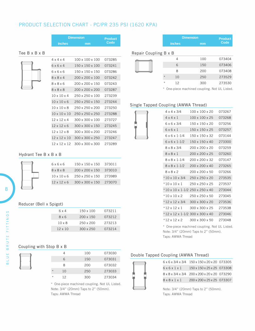
Tee B x B x B
Reducer (Bell x Spigot)
Coupling with Stop B x B
Repair Coupling B x B
Double Tapped Coupling (AWWA Thread)
4 x 4 x 4 100 x 100 x 100 073285
6 x 6 x 4 150 x 150 x 100 073241
6 x 6 x 6 150 x 150 x 150 073286
8 x 8 x 4 200 x 200 x 100 073242
8 x 8 x 6 200 x 200 x 150 073243
8 x 8 x 8 200 x 200 x 200 073287
10 x 10 x 4 250 x 250 x 100 273239
10 x 10 x 6 250 x 250 x 150 273244
10 x 10 x 8 250 x 250 x 200 273250
10 x 10 x 10 250 x 250 x 250 273288
12 x 12 x 4 300 x 300 x 100 273727
12 x 12 x 6 300 x 300 x 150 273245
12 x 12 x 8 300 x 300 x 200 273246
12 x 12 x 10 300 x 300 x 250 273247
12 x 12 x 12 300 x 300 x 300 273289
6 x 4 150 x 100 073211
8 x 6 200 x 150 073212
10 x 8 250 x 200 273213
12 x 10 300 x 250 073214
4 100 073030
6 150 073031
8 200 073032
* 10 250 273033
* 12 300 273034
4 100 073404
6 150 073406
8 200 073408
* 10 250 273529
* 12 300 273530
6 x 6 x 3/4 x 3/4 150 x 150 x 20 x 20 073305
6 x 6 x 1 x 1 150 x 150 x 25 x 25 073308
8 x 8 x 3/4 x 3/4 200 x 200 x 20 x 20 073290
8 x 8 x 1 x 1 200 x 200 x 25 x 25 073307
PRODUCT SELECTION CHART - PC/PR 235 PSI (1620 KPA)
Single Tapped Coupling (AWWA Thread)
4 x 4 x 3/4 100 x 100 x 20 073267
4 x 4 x 1 100 x 100 x 25 073268
6 x 6 x 3/4 150 x 150 x 20 073256
6 x 6 x 1 150 x 150 x 25 073257
6 x 6 x 1-1/4 150 x 150 x 32 073144
6 x 6 x 1-1/2 150 x 150 x 40 273300
8 x 8 x 3/4 200 x 200 x 20 073259
8 x 8 x 1 200 x 200 x 25 073260
8 x 8 x 1-1/4 200 x 200 x 32 073147
8 x 8 x 1-1/2 200 x 200 x 40 273265
8 x 8 x 2 200 x 200 x 50 073266
*10 x 10 x 3/4 250 x 250 x 20 273535
*10 x 10 x 1 250 x 250 x 25 273537
*10 x 10 x 1-1/2 250 x 250 x 40 273044
*10 x 10 x 2 250 x 250 x 50 273045
*12 x 12 x 3/4 300 x 300 x 20 273536
*12 x 12 x 1 300 x 300 x 25 273538
*12 x 12 x 1-1/2 300 x 300 x 40 273046
*12 x 12 x 2 300 x 300 x 50 273048
Hydrant Tee B x B x B
6 x 6 x 6 150 x 150 x 150 373011
8 x 8 x 8 200 x 200 x 150 373010
10 x 10 x 6 250 x 250 x 150 273989
12 x 12 x 6 300 x 300 x 150 273070
* One-piece machined coupling. Not UL Listed.
Note: 3/4” (20mm) Taps to 2” (50mm).
Taps: AWWA Thread
* One-piece machined coupling. Not UL Listed.
Note: 3/4” (20mm) Taps to 2” (50mm).
Taps: AWWA Thread
* One-piece machined coupling. Not UL Listed.
Note: 3/4” (20mm) Taps to 2” (50mm).
Taps: AWWA Thread
BL
UE
B
RU
TE
F
ITT
ING
S
9
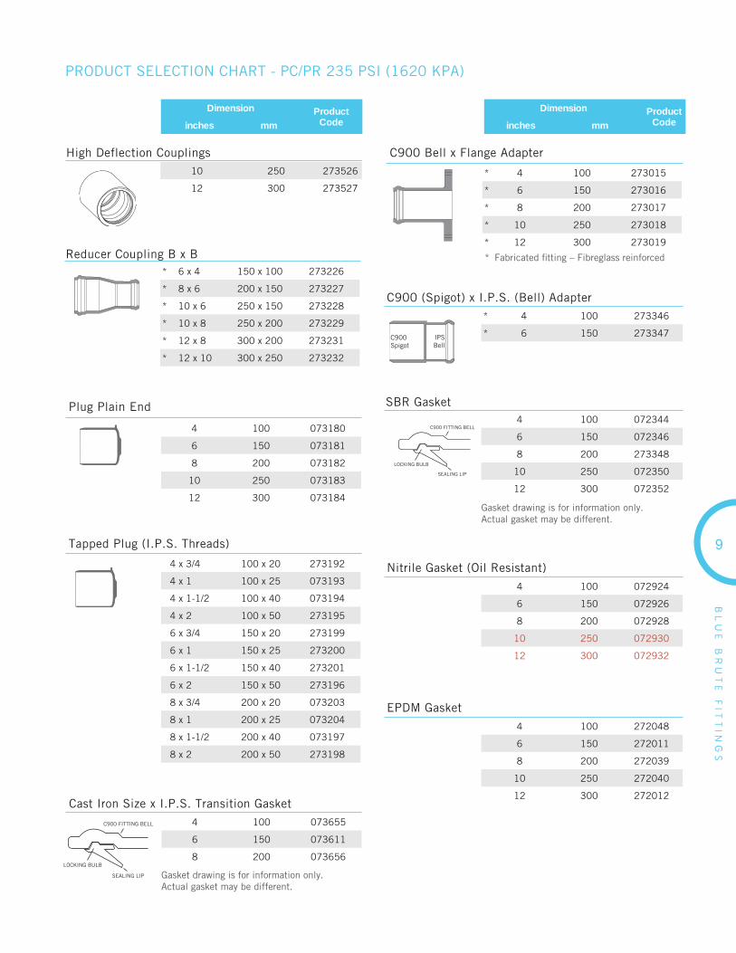
Reducer Coupling B x B
C900 (Spigot) x I.P.S. (Bell) Adapter
SBR Gasket
Nitrile Gasket (Oil Resistant)
C900Spigot
IPSBell
C900 FITTING BELL
SEALING LIP
LOCKING BULB
* 6 x 4 150 x 100 273226
* 8 x 6 200 x 150 273227
* 10 x 6 250 x 150 273228
* 10 x 8 250 x 200 273229
* 12 x 8 300 x 200 273231
* 12 x 10 300 x 250 273232
* 4 100 273346
* 6 150 273347
4 100 072344
6 150 072346
8 200 273348
10 250 072350
12 300 072352
4 100 072924
6 150 072926
8 200 072928
10 250 072930
12 300 072932
PRODUCT SELECTION CHART - PC/PR 235 PSI (1620 KPA)
Dimension ProductCodeinches mm
Dimension ProductCodeinches mm
High Deflection Couplings10 250 273526
12 300 273527
EPDM Gasket
4 100 272048
6 150 272011
8 200 272039
10 250 272040
12 300 272012
Gasket drawing is for information only. Actual gasket may be different.
Plug Plain End
C900 Bell x Flange Adapter
Tapped Plug (I.P.S. Threads)
C900 FITTING BELL
SEALING LIP
LOCKING BULB
4 x 3/4 100 x 20 273192
4 x 1 100 x 25 073193
4 x 1-1/2 100 x 40 073194
4 x 2 100 x 50 273195
6 x 3/4 150 x 20 273199
6 x 1 150 x 25 273200
6 x 1-1/2 150 x 40 273201
6 x 2 150 x 50 273196
8 x 3/4 200 x 20 073203
8 x 1 200 x 25 073204
8 x 1-1/2 200 x 40 073197
8 x 2 200 x 50 273198
4 100 073180
6 150 073181
8 200 073182
10 250 073183
12 300 073184
4 100 073655
6 150 073611
8 200 073656
* 4 100 273015
* 6 150 273016
* 8 200 273017
* 10 250 273018
* 12 300 273019
Cast Iron Size x I.P.S. Transition Gasket
Gasket drawing is for information only. Actual gasket may be different.
* Fabricated fi tting – Fibreglass reinforced

BIONAX PVCOPRESSURE PIPE 4” - 30” (100mm - 750mm)
10
BIO
NA
X
PV
CO
P
RE
SS
UR
E
PIP
E
• Water Mains
• Sewage Forcemains
• Industrial Process Piping
APPLICATIONS
STANDARDS
Imagine a pipe with all the benefi ts associated with conventional PVC,yet dramatically stronger and more impact resistant.
Bionax is a molecularly-enhanced PVC pipe designed for water mains, sewage forcemains and industrial process piping. Made from biaxially-oriented PVC material, Bionax has almost double the strength of conventional PVC and three times the impact absorption capability. Using a revolutionary new orientation process, this high-tech process orients the PVC molecules both in the axial and circumferential directions (biaxial orientation). The result is a pipe with enhanced toughness and fl exibility.
Bionax is specially engineered to withstand the rigors of today’s installations. With less construction inspection and less regular maintenance, the market is calling for a pipe that is more robust, stronger and easier to install. Bionax delivers on all three counts.
Biaxially Oriented PVC Pipe for Municipal Applications
Bionax’s biaxial orientation dramatically enhances the pipeproperties that are important to municipal designers:
• Larger internal diameters increase fl ow rates and reduce pumping costs
• Higher cyclic fatigue resistance for forcemain and irrigation applications
• Reduced bend radius when compared to standard PVC pipe
D1784D3139F477
F1483
B137.3.1 NSF 14NSF 61
Circumferential Tensile StrengthBionax has almost double the tensile strength of conventional PVC (12,100 psi vs. 7,000 psi). This higher strength results in larger inside diameters, improving the hydraulics of the pipe.
Impact StrengthBionax provides more than triple the impact strength of standard PVC pipe. PVCO pipe can withstand extreme jobsite conditions with no damage.
Crack ResistancePVCO’s laminar structure prevents crack propagation, preventing damage to the pipe.
Longitudinal Tensile StrengthBionax has higher tensile strength in the axial direction, which allows a tighter bend radius than other materials.
Certifi cationBionax is third party certifi ed to CSA B137.3.1 and AWWA C909.
FEATURES & BENEFITS
1
2
3
4
5
11
BIO
NA
X
PV
CO
P
RE
SS
UR
E
PIP
E
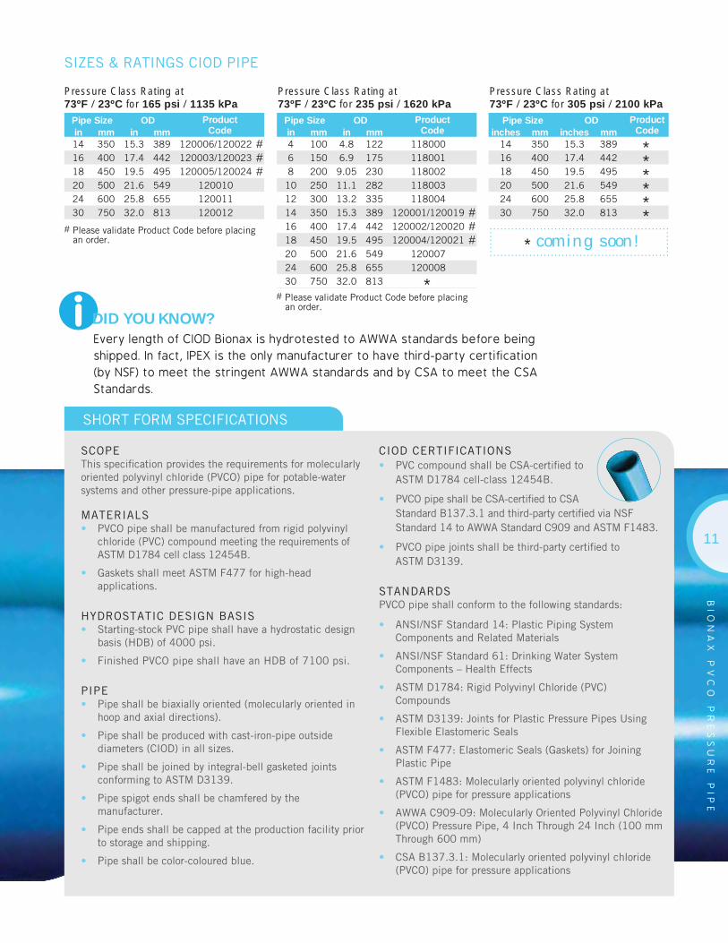
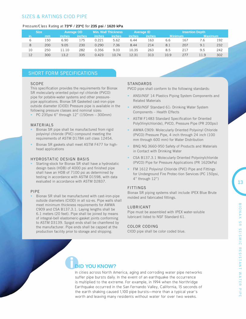
i DID YOU KNOW?Every length of CIOD Bionax is hydrotested to AWWA standards before being shipped. In fact, IPEX is the only manufacturer to have third-party certification (by NSF) to meet the stringent AWWA standards and by CSA to meet the CSA Standards.
SCOPEThis specifi cation provides the requirements for molecularly oriented polyvinyl chloride (PVCO) pipe for potable-water systems and other pressure-pipe applications.
MATERIALS• PVCO pipe shall be manufactured from rigid polyvinyl
chloride (PVC) compound meeting the requirements of ASTM D1784 cell class 12454B.
• Gaskets shall meet ASTM F477 for high-head applications.
HYDROSTATIC DESIGN BASIS• Starting-stock PVC pipe shall have a hydrostatic design
basis (HDB) of 4000 psi.
• Finished PVCO pipe shall have an HDB of 7100 psi.
PIPE• Pipe shall be biaxially oriented (molecularly oriented in
hoop and axial directions).
• Pipe shall be produced with cast-iron-pipe outside diameters (CIOD) in all sizes.
• Pipe shall be joined by integral-bell gasketed joints conforming to ASTM D3139.
• Pipe spigot ends shall be chamfered by the manufacturer.
• Pipe ends shall be capped at the production facility prior to storage and shipping.
• Pipe shall be color-coloured blue.
CIOD CERTIFICATIONS• PVC compound shall be CSA-certifi ed to
ASTM D1784 cell-class 12454B.
• PVCO pipe shall be CSA-certifi ed to CSA Standard B137.3.1 and third-party certifi ed via NSF Standard 14 to AWWA Standard C909 and ASTM F1483.
• PVCO pipe joints shall be third-party certifi ed to ASTM D3139.
STANDARDSPVCO pipe shall conform to the following standards:
• ANSI/NSF Standard 14: Plastic Piping System Components and Related Materials
• ANSI/NSF Standard 61: Drinking Water System Components – Health Effects
• ASTM D1784: Rigid Polyvinyl Chloride (PVC) Compounds
• ASTM D3139: Joints for Plastic Pressure Pipes Using Flexible Elastomeric Seals
• ASTM F477: Elastomeric Seals (Gaskets) for Joining Plastic Pipe
• ASTM F1483: Molecularly oriented polyvinyl chloride (PVCO) pipe for pressure applications
• AWWA C909-09: Molecularly Oriented Polyvinyl Chloride (PVCO) Pressure Pipe, 4 Inch Through 24 Inch (100 mm Through 600 mm)
• CSA B137.3.1: Molecularly oriented polyvinyl chloride (PVCO) pipe for pressure applications
SHORT FORM SPECIFICATIONS
SIZES & RATINGS CIOD PIPE
Pressure Class Rating at 73ºF / 23ºC for 165 psi / 1135 kPa
Pipe Size OD ProductCodein mm in mm
14 350 15.3 389 120006/120022 #16 400 17.4 442 120003/120023 #18 450 19.5 495 120005/120024 #20 500 21.6 549 12001024 600 25.8 655 12001130 750 32.0 813 120012
Pressure Class Rating at 73ºF / 23ºC for 235 psi / 1620 kPa
Pipe Size OD ProductCodein mm in mm
4 100 4.8 122 1180006 150 6.9 175 1180018 200 9.05 230 118002
10 250 11.1 282 11800312 300 13.2 335 11800414 350 15.3 389 120001/120019 #16 400 17.4 442 120002/120020 #18 450 19.5 495 120004/120021 #20 500 21.6 549 12000724 600 25.8 655 12000830 750 32.0 813 *
Pressure Class Rating at 73ºF / 23ºC for 305 psi / 2100 kPa
Pipe Size OD ProductCodeinches mm inches mm
14 350 15.3 389 *16 400 17.4 442 *18 450 19.5 495 *20 500 21.6 549 *24 600 25.8 655 *30 750 32.0 813 *
* coming soon!
# Please validate Product Code before placing an order.
# Please validate Product Code before placing an order.

BIONAX SR SEISMIC WATER PIPE 6” - 12” (150mm - 300mm)
12
BIO
NA
X S
R S
EIS
MIC
RE
SIS
TA
NT
WA
TE
R P
IPE
• Municipal Water Systems
• Fire Lines
• Industrial Lines
• Foremains
APPLICATIONS
STANDARDS
Bionax SRTM – Seismic Water Pipe - combines the same strength, toughness and fl exibility as standard Bionax pipe with the enhanced seismic-resistance benefi ts of an extended bell. The result is a municipal water transmission and distribution system which performs better than any pipe product available today. Bionax SR can absorb lateral ground strain of seismic events and provides other performance benefi ts including product consistency, industry standard dimensions and corrosion-resistant attributes for a North American jobsite.
The biaxial orientation and the extended bell of Bionax SR pipe provide excellent pipe and joint fl exibility—precisely what is required from a water pipe if it is to remain intact after a seismic event.
Circumferential Tensile StrengthBionax SR has almost double the tensile strength of conventional PVC (12,100 psi vs. 7,000 psi). This higher strength results in larger inside diameters, improving the hydraulics of the pipe.
Impact StrengthBionax SR provides more than triple the impact strength of standard PVC pipe. PVCO pipe can withstand extreme jobsite conditions with no damage.
Crack ResistancePVCO’s laminar structure prevents crack propagation, preventing damage to the pipe.
Longitudinal Tensile StrengthBionax SR has higher tensile strength in the axial direction, which allows a tighter bend radius than other materials.
Light-weighte.g. 300mm PC 235 psi pipe = 236 lbs.
Corrosion-proof & Consistent O.D.
Certifi cationBionax SR is third party certifi ed to CSA B137.3.1 and AWWA C909.
FEATURES & BENEFITS
1
2
3
4
5
6
7
13
iDID YOU KNOW?In cities across North America, aging and corroding water pipe networks suffer pipe bursts daily. In the event of an earthquake the occurrence is multiplied to the extreme. For example, in 1994 when the Northridge Earthquake occurred in the San Fernando Valley, California, 15 seconds of the earth shaking caused 1,100 pipe bursts—more than a typical year’s worth and leaving many residents without water for over two weeks.
SCOPEThis specifi cation provides the requirements for Bionax SR molecularly oriented polyvi-nyl chloride (PVCO) pipe for potable-water systems and other pressure-pipe applications. Bionax SR Gasketed cast-iron-pipe outside diameter (CIOD) Pressure pipe is available in the following pressure classes and nominal sizes:• PC 235psi 6” through 12” (150mm – 300mm)
MATERIALS• Bionax SR pipe shall be manufactured from rigid
polyvinyl chloride (PVC) compound meeting the requirements of ASTM D1784 cell class 12454.
• Bionax SR gaskets shall meet ASTM F477 for high-head applications
HYDROSTATIC DESIGN BASIS• Starting-stock for Bionax SR shall have a hydrostatic
design basis (HDB) of 4000 psi and fi nished pipe shall have an HDB of 7100 psi as determined by testing in accordance with ASTM D1598, with data evaluated in accordance with ASTM D2837.
PIPE• Bionax SR shall be manufactured with cast-iron-pipe
outside diameters (CIOD) in all siz-es. Pipe walls shall meet minimum thickness requirements for AWWA C909 and CSA B137.3.1. Laying lengths shall be 6.1 meters (20 feet). Pipe shall be joined by means of integral-bell elastomeric-gasket joints conforming to ASTM D3139. Spigot ends shall be chamfered by the manufacturer. Pipe ends shall be capped at the production facility prior to storage and shipping.
STANDARDSPVCO pipe shall conform to the following standards:
• ANSI/NSF 14 Plastics Piping System Components and Related Materials
• ANSI/NSF Standard 61: Drinking Water System Components – Health Effects
• ASTM F1483 Standard Specifi cation for Oriented Poly(Vinylchloride), PVCO, Pressure Pipe (PR 200psi)
• AWWA C909: Molecularly Oriented Polyvinyl Chloride (PVCO) Pressure Pipe, 4 inch through 24 inch (100 mm through 600 mm) for Water Distribution
• BNQ NQ 3660-950 Safety of Products and Materials in Contact with Drinking Water
• CSA B137.3.1 Molecularly Oriented Polyvinylchloride (PVCO) Pipe for Pressure Applications (PR 1620kPa)
• FM 1612 Polyvinyl Chloride (PVC) Pipe and Fittings for Underground Fire Protec-tion Services (PC 150psi, 4” through 12”)
FITTINGSBionax SR piping systems shall include IPEX Blue Brute molded and fabricated fi ttings.
LUBRICANTPipe must be assembled with IPEX water-soluble lubricant listed to NSF Standard 61.
COLOR CODINGCIOD pipe shall be color coded blue.
SHORT FORM SPECIFICATIONS
Size Average OD Min. Wall Thickness Average ID Insertion Depthin. mm inches inches inches inches inches inches Minimum Maximum6 150 6.90 175 0.221 5.62 6.44 163 6.6 167 7.6 192
8 200 9.05 230 0.290 7.36 8.44 214 8.1 207 9.1 232
10 250 11.10 282 0.356 9.03 10.35 263 8.5 217 9.5 242
12 300 13.2 335 0.423 10.74 12.31 313 10.9 277 11.9 302
SIZES & RATINGS CIOD PIPE
Pressure/Class Rating at 73ºF / 23ºC for 235 psi / 1620 kPa
BIO
NA
X S
R S
EIS
MIC
RE
SIS
TA
NT
WA
TE
R P
IPE
IPEX CENTURIONPRESSURE PIPING SYSTEMS 14” - 60” (350mm - 1500mm)
14
IPE
X
CE
NT
UR
ION
• Water Transmission Lines
• Forcemains
• Gravity Lines
• Irrigation
• Industrial Lines
APPLICATIONS
STANDARDS
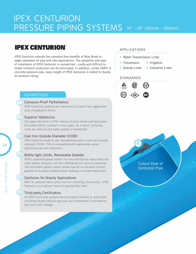
IPEX Centurion extends the corrosion-free benefi ts of Blue Brute to larger diameters of pipe and new applications. The versatility and ease of installation of IPEX Centurion is unmatched – costly and diffi cult to install corrosion protection can be eliminated. In addition, unlike HDPE or concrete pressure pipe, every length of IPEX Centurion is tested to double its pressure rating.
Cutout View ofCenturion Pipe
4
ADVANTAGES
Corrosion-Proof PerformanceIPEX Centurion systems are immune to corrosion from aggressive soils and galvanic action.
Superior HydraulicsThe glass-like fi nish of PVC reduces friction losses and eliminates the tuberculation common in iron pipes. As a result, pumping costs are reduced and water quality is maintained.
Cast Iron Outside Diameter (CIOD)IPEX Centurion systems are manufactured with a cast iron outside diameter (CIOD). This is compatible with waterworks valves, appurtenances and restrainers.
Bottle-tight Joints, Removable GasketsIPEX’s patented gasket system not only withstands many times the rated system pressure, but also withstands full vacuum pressures.The removable gasket system allows special oil-resistant (nitrile) gaskets to be easily installed when working in contaminated soils.
Centurion for Gravity ApplicationsWith its pressure rated joints and non-corroding construction, IPEX Centurion is a natural choice for gravity fl ow lines.
Third-party Certifi cationAll IPEX municipal systems are third-party certifi ed as applicable including Factory Mutual approval and Underwriter’s Laboratories (ULI and ULC) listings.
1
2
3
4
5
6
15
IPE
X
CE
NT
UR
ION
PRESSURE CAPACITY
IPEX Centurion can withstand extremely high short-term pressures in addition to lower levels of long-term pressure. As a result CSA B137.3 and AWWA C905 include both long-term pressure capacity (pressure rating PR or pressure class PC) and short-term capacity (short-term rating STR).
SDR Short Term RatingSTR psi
Long Term RatingPC/PR psi
51 128 80
41 160 100
32.5 200 125
25 264 165
18 376 235
14 488 305
STANDARDSAWWA C905, CSA B137.3, NQ 3624-250, NSF-61
Factory Mutual FM 1612:DR18 is FM approved to 500mm diameter (20”)
Underwriter’s Laboratories UL 1285: DR18 is listed to 600mm diameter (24”)DR25 is listed to 750mm diameter (30”)
COMPATIBILITY
IPEX Centurion is manufactured with a cast iron outside diameter (CIOD) so it is compatible with much of the existing older infrastructure of iron pipes. In addition, IPEX Centurion can be fi eld cut, which means unexpected changes in the fi eld can be accommodated quickly, without having to wait for new shop drawings.
IPEX Centurion Fittings are manufactured using sections ofAWWA C905 pipe that are fused or bonded together. Some fi ttings are overwrapped with a layer of fi bre reinforced plastic (FRP). While IPEX Centurion is compatible with iron fi ttings, IPEX recommends the use of IPEX Centurion fi ttings exclusively with IPEX Centurion pipe.
SHORT FORM SPECIFICATIONS
GENERALPipe must conform to AWWA C905 and be certifi ed to CSA B137.3 “Rigid Poly (Vinyl Chloride) (PVC) Pipe for Pressure Applications.” DR51, 41, 32.5, 25, 18, and 14 pipe must have the following pressure class/rating: 80 psi (550 kPa), 100 psi (690 kPa), 125 psi (860 kPa), 165 psi (1 140 kPa), 235 psi (1 620 kPa) and 305 psi
(2 100 kPa). For pressure applications, each length of pipe must be hydro-tested at twice the class/rating and a short-term pressure test must be conducted once per production run. Pipe to be IPEX Centurion or approved equal.
FABRICATED FITTINGSFabricated fi ttings shall be made from segments of AWWA C905 pipe that are butt fused or bonded together. Some fi ttings are over-wrapped with fi berglass-reinforced polyester. The fi ttings must always meet the pressure rating of the pipe system.

IPE
X
CE
NT
UR
ION
16
Size ProductCode
Avg. ID Min. WallThickness Avg. OD
in mm in mm in mm in mm
PC/PR 80(SDR51)
18 450 071004 18.7 475.9 0.38 9.7 19.5 495.320 500 071520 20.8 527.0 0.42 10.8 21.6 548.624 600 071524 24.8 629.6 0.50 12.9 25.8 655.330 750 071526 30.7 780.9 0.63 15.9 32.0 812.836 900 071528 36.8 934.7 0.75 19.1 38.3 972.842 1050 071000 42.6 1082.8 0.87 22.2 44.5 1130.348 1200 071135 48.7 1236.2 1.00 25.3 50.8 1290.354 1350 071043 55.3 1404.6 1.13 28.7 57.6 1462.060 1500 071044 59.2 1503.2 1.21 30.7 61.6 1564.9
PC/PR 100(SDR41)
14 350 071414 14.6 369.7 0.37 9.5 15.3 388.616 400 071416 16.6 420.4 0.43 10.8 17.4 442.018 450 071418 18.5 471.1 0.48 12.1 19.5 495.320 500 071420 20.5 521.8 0.53 13.4 21.6 548.624 600 071424 24.5 623.3 0.63 16.0 25.8 655.330 750 071426 30.4 773.2 0.78 19.8 32.0 812.836 900 071428 36.4 925.3 0.93 23.7 38.3 972.842 1050 071140 42.2 1071.4 1.09 27.5 44.5 1130.348 1200 071223 48.2 1223.0 1.24 31.5 50.8 1290.354 1350 071045 54.8 1391.9 1.40 35.7 57.6 1462.060 1500 071046 58.6 1488.4 1.50 38.1 61.6 1564.9
PC/PR 125(SDR32.5)
14 350 – 14.4 364.7 0.47 12.0 15.3 388.616 400 071316 16.3 414.5 0.54 13.6 17.4 442.018 450 071317 18.3 464.8 0.60 15.2 19.5 495.320 500 071320 20.3 514.6 0.67 16.9 21.6 548.624 600 071324 24.2 615.0 0.80 20.2 25.8 655.330 750 071326 30.0 762.8 0.98 25.0 32.0 812.836 900 071328 35.9 912.9 1.18 29.9 38.3 972.842 1050 071219 41.6 1056.6 1.37 34.8 44.5 1130.348 1200 – 47.7* 1211.1* 1.56* 39.6* 50.8* 1290.3*54 1350 – 54.1* 1374.1* 1.77* 45.0* 57.6* 1462.0*
PC/PR 165(DR25)
14 350 071114 14.1 357.5 0.61 15.6 15.3 388.616 400 071116 16.0 406.6 0.70 17.7 17.4 442.018 450 071118 17.9 455.7 0.78 19.8 19.5 495.320 500 071124 19.9 504.7 0.86 22.0 21.6 548.624 600 071136 23.7 602.9 1.03 26.2 25.8 655.330 750 071144 29.4 747.8 1.28 32.5 32.0 812.836 900 071137 35.2 895.0 1.53 38.9 38.3 972.842 1050 – 40.9* 1039.9* 1.78* 45.2* 44.5* 1130.3*48 1200 – 46.7* 1187.2* 2.03* 51.6* 50.8* 1290.3*
PC/PR 235(DR18)
14 350 071214 13.6 345.4 0.85 21.6 15.3 388.616 400 071216 15.5 392.9 0.97 24.6 17.4 442.018 450 071218 17.3 440.3 1.08 27.5 19.5 495.320 500 071220 19.2 487.6 1.20 30.5 21.6 548.624 600 071224 22.9 582.5 1.43 36.4 25.8 655.330 750 071130 28.4 722.4 1.78 45.2 32.0 812.836 900 – 34.0* 863.6* 2.13* 54.1* 38.3* 972.8*42 1050 – 39.6* 1004.8* 2.47* 62.8* 44.5* 1130.3*
IPEX CENTURIONTM
LARGE DIAMETER CIOD PVC PRESSURE PIPE
PC/PR 305(DR14)
14 350 – 13.1 333.0 1.09 27.8 15.3 388.6
16 400 070426 14.9 378.8 1.24 31.6 17.4 442.0
* coming soon!

IPE
X
CE
NT
UR
ION
17
IPEX CENTURIONTM
FABRICATED FITTINGS (CIOD), CLASS/PRESSURE RATING 165 PSI
Dimension ProductCodeinches mm
Dimension ProductCodeinches mm
90o Bend Reducer Tee G x G x G
Tee
45o Bend
22-1/2o Bend
11-1/4o Bend
14 350 073709
16 400 073040
18 450 073710
20 500 073711
24 600 073712
30 750 073713
14 350 073140
16 400 073714
18 450 073715
20 500 073716
24 600 073160
30 750 073038
14 350 073717
16 400 073718
18 450 073719
20 500 073720
24 600 073161
30 750 073721
14 x 4 350 x 100 073728
14 x 6 350 x 150 073729
14 x 8 350 x 200 073730
14 x 10 350 x 250 073731
14 x 12 350 x 300 073732
16 x 4 400 x 100 073734
16 x 6 400 x 150 073735
16 x 8 400 x 200 073736
16 x 10 400 x 250 073737
16 x 12 400 x 300 073738
16 x 14 400 x 350 073739
18 x 4 450 x 100 073740
18 x 6 450 x 150 073741
18 x 8 450 x 200 073742
18 x 10 450 x 250 073743
18 x 12 450 x 300 073744
18 x 14 450 x 350 073745
18 x 16 450 x 400 073746
20 x 4 500 x 100 073748
20 x 6 500 x 150 073749
20 x 8 500 x 200 073750
20 x 10 500 x 250 073751
20 x 12 500 x 300 073752
20 x 14 500 x 350 073753
20 x 16 500 x 400 073754
20 x 18 500 x 450 073755
24 x 4 600 x 100 073757
24 x 6 600 x 150 073758
24 x 8 600 x 200 073759
24 x 10 600 x 250 073760
24 x 12 600 x 300 073761
24 x 14 600 x 350 073762
24 x 16 600 x 400 073763
24 x 18 600 x 450 073764
24 x 20 600 x 500 073765
30 x 4 750 x 100 073767
30 x 6 750 x 150 073011
30 x 8 750 x 200 073013
30 x 10 750 x 250 073768
30 x 12 750 x 300 073769
30 x 14 750 x 350 073770
30 x 16 750 x 400 073039
30 x 18 750 x 450 073771
30 x 20 750 x 500 073772
30 x 24 750 x 600 073773
14 350 073733
16 400 073427
18 450 073747
20 500 073756
24 600 073766
30 750 073774
14 350 073722
16 400 073723
18 450 073724
20 500 073725
24 600 073162
30 750 073726

IPE
X
CE
NT
UR
ION
18
Dimension ProductCodeinches mm
Dimension ProductCodeinches mm
14 x 4 350 x 100 073776
14 x 6 350 x 150 073777
14 x 8 350 x 200 073778
14 x 10 350 x 250 073779
14 x 12 350 x 300 073780
16 x 4 400 x 100 073781
16 x 6 400 x 150 073782
16 x 8 400 x 200 073783
16 x 10 400 x 250 073784
16 x 12 400 x 300 073785
16 x 14 400 x 350 073786
18 x 4 450 x 100 073787
18 x 6 450 x 150 073788
18 x 8 450 x 200 073789
18 x 10 450 x 250 073790
18 x 12 450 x 300 073791
18 x 14 450 x 350 073792
18 x 16 450 x 400 073793
20 x 4 500 x 100 073794
20 x 6 500 x 150 073795
20 x 8 500 x 200 073796
20 x 10 500 x 250 073797
20 x 12 500 x 300 073798
20 x 14 500 x 350 073799
20 x 16 500 x 400 073800
20 x 18 500 x 450 073801
24 x 4 600 x 100 073802
24 x 6 600 x 150 073803
24 x 8 600 x 200 073804
24 x 10 600 x 250 073805
24 x 12 600 x 300 073806
24 x 14 600 x 350 073807
24 x 16 600 x 400 073808
24 x 18 600 x 450 073809
24 x 20 600 x 500 073813
30 x 4 750 x 100 073814
30 x 6 750 x 150 073815
30 x 8 750 x 200 073816
30 x 10 750 x 250 073817
30 x 12 750 x 300 073818
30 x 14 750 x 350 073819
30 x 16 750 x 400 073820
30 x 18 750 x 450 073821
30 x 20 750 x 500 073822
30 x 24 750 x 600 073234
Reducer Coupling G x G
14 350 073883
16 400 073884
18 450 073885
20 500 073886
24 600 073887
30 750 073425
Repair Coupling
14 350 073890
16 400 073891
18 450 073892
20 500 073893
24 600 073163
30 750 073894
14 350 073895
16 400 073896
18 450 073897
20 500 073898
24 600 073899
30 750 073900
14 350 073837
16 400 073844
18 450 073852
20 500 073861
24 600 073871
30 750 073882
Stop Coupling
Cap
Cross
IPEX CENTURIONTM
FABRICATED FITTINGS (CIOD), CLASS/PRESSURE RATING 165 PSI
IPE
X
CE
NT
UR
ION
19
IPEX CENTURIONTM
FABRICATED FITTINGS (CIOD), CLASS/PRESSURE RATING 165 PSI
14 x 4 350 x 100 073832
14 x 6 350 x 150 073833
14 x 8 350 x 200 073834
14 x 10 350 x 250 073835
14 x 12 350 x 300 073836
16 x 4 400 x 100 073838
16 x 6 400 x 150 073839
16 x 8 400 x 200 073840
16 x 10 400 x 250 073841
16 x 12 400 x 300 073842
16 x 14 400 x 350 073843
18 x 4 450 x 100 073845
18 x 6 450 x 150 073846
18 x 8 450 x 200 073847
18 x 10 450 x 250 073848
18 x 12 450 x 300 073849
18 x 14 450 x 350 073850
18 x 16 450 x 400 073851
20 x 4 500 x 100 073853
20 x 6 500 x 150 073854
20 x 8 500 x 200 073855
20 x 10 500 x 250 073856
20 x 12 500 x 300 073857
20 x 14 500 x 350 073858
20 x 16 500 x 400 073859
20 x 18 500 x 450 073860
Reducer Cross G x G x G x G
Dimension ProductCodeinches mm
24 x 4 600 x 100 073862
24 x 6 600 x 150 073863
24 x 8 600 x 200 073864
24 x 10 600 x 250 073865
24 x 12 600 x 300 073866
24 x 14 600 x 350 073867
24 x 16 600 x 400 073868
24 x 18 600 x 450 073869
24 x 20 600 x 500 073870
30 x 4 750 x 100 073872
30 x 6 750 x 150 073873
30 x 8 750 x 200 073874
30 x 10 750 x 250 073875
30 x 12 750 x 300 073876
30 x 14 750 x 350 073877
30 x 16 750 x 400 073878
30 x 18 750 x 450 073879
30 x 20 750 x 500 073880
30 x 24 750 x 600 073881
Dimension ProductCodeinches mm

IPEX FUSIBLE PIPE12.2m (40 ft) lengths
CIOD: 100mm - 750mm (4” - 30”)IPS: 300mm – 750mm (12”-30”)
20
IPE
X
FU
SIB
LE
• Water Mains • Sanitary Sewers
• Process and Raw Water
• Reclaimed Water • Storm Drains
APPLICATIONS
STANDARDS
B137.3 12454
IPEX has introduced new Fusible BruteTM and Fusible SeriesTM PVC pipes.By combining the mechanical properties of PVC with an innovative, patented butt fusion process, IPEX provides the only available method of installing a continuous, monolithic, fully restrained PVC pipe system. Capable of being used in a variety of trenchless or conventional direct bury applications, Fusible PVCTM pipe systems have been installed at numerous sites throughout the United States, Canada and Mexico for both pressure and non-pressure installations in the water and sewer industries.
With PVC’s proven long service life, Fusible Brute (CIOD) and Fusible Series (IPS) pipes are available in sizes ranging from 100mm (4”) to 750mm (30”) with larger sizes in development. The proprietary PVC formulation, fusion process as well as our licensing and training program allow for the consistent, reliable fusion of Fusible Brute and Fusible Series pipes tocreate piping systems of unparalleled strength.
ADVANTAGESADVANTAGES
✓ Greater pull force rating than HDPE.
✓ Greater pull force rating than other PVC systems.
✓ Lower installation costs versus HDPE due to lighter weight and reduced OD dimensions.
✓ Has excellent abrasion and scratch-resistant properties.
✓ Higher fl ow rates.
✓ Connects directly to existing PVC systems formaterial consistency.
✓ Uses standard CIOD or IPS fi ttings.
✓ Creates monolithic, fully-restrained pipe systems.
i DID YOU KNOW?Reduced wall thickness relative to HDPE yields more flow and less material for a given pressure class

21
IPE
X
FU
SIB
LE
Dimension Ratio Pressure (psi)
DR 14 305
DR 18 235
DR 25 165
DR 32.5 125
DR 41 100
Dimension Ratio Pressure (psi)
DR 21 200
DR 26 160
PRESSURE RATINGS
(CIOD)
(IPS)
For job quotation, contact your IPEX representative.
FUSION IN ACTION
ALBERTASlipline, Epcor 92nd St & 106a Ave, Edmonton, Alberta85.4m (280 LF) of 400mm (16") DR25
ONTARIOCentral Experimental Farm, Ottawa, Ontario573m (1,880 LF) of 300mm (12") DR18,353m (1,158 LF) of 250mm (10") DR25,170m (558 LF) of 450mm (14") DR25
Fusible PVC was chosen because of less disruption to federally protected land and forest. Also because of traffi c control constraints.
MANITOBAGrosse Isle Watermain, Manitoba1,000m (3,281 LF) of 150mm (6") DR18,3,000m (9,843 LF) of 150mm (6") DR25
Fusible PVC was chosen to minimize restoration costs.
QUEBECDirect Bury, St-Henri-de-Taillon, Quebec5,563.2m (18,252 LF) of 150mm (6") DR25,10,614m (34,823 LF) of 200mm (8") DR25,610m (2,001 LF) of 250mm (10") DR25
Fusible PVC was chosen for ease of installation and lower cost.
DR25 Fusible Brute was chosen as it offered the optimal fl ow characteristics for that slipline.

TERRABRUTE CR 4” - 12” (100mm - 300mm)
22
TE
RR
AB
RU
TE
C
R
• Municipal Water Systems
• Fire Lines
• Industrial Lines
• Forcemains
APPLICATIONS
STANDARDS
Engineered for Horizontal Directional Drilling (HDD) and other trenchless applications, TerraBrute® CR is a 100% non-metallic, CSA B137.3 / AWWA C900 PVC pressure pipe system. Non-corroding and installation friendly, TerraBrute CR allows you to standardize on PVC throughout your potable water and sewer infrastructure. Whether you’re using open-cut or trenchless methods, there are no more problems matching materials and couplings. No more surprises.
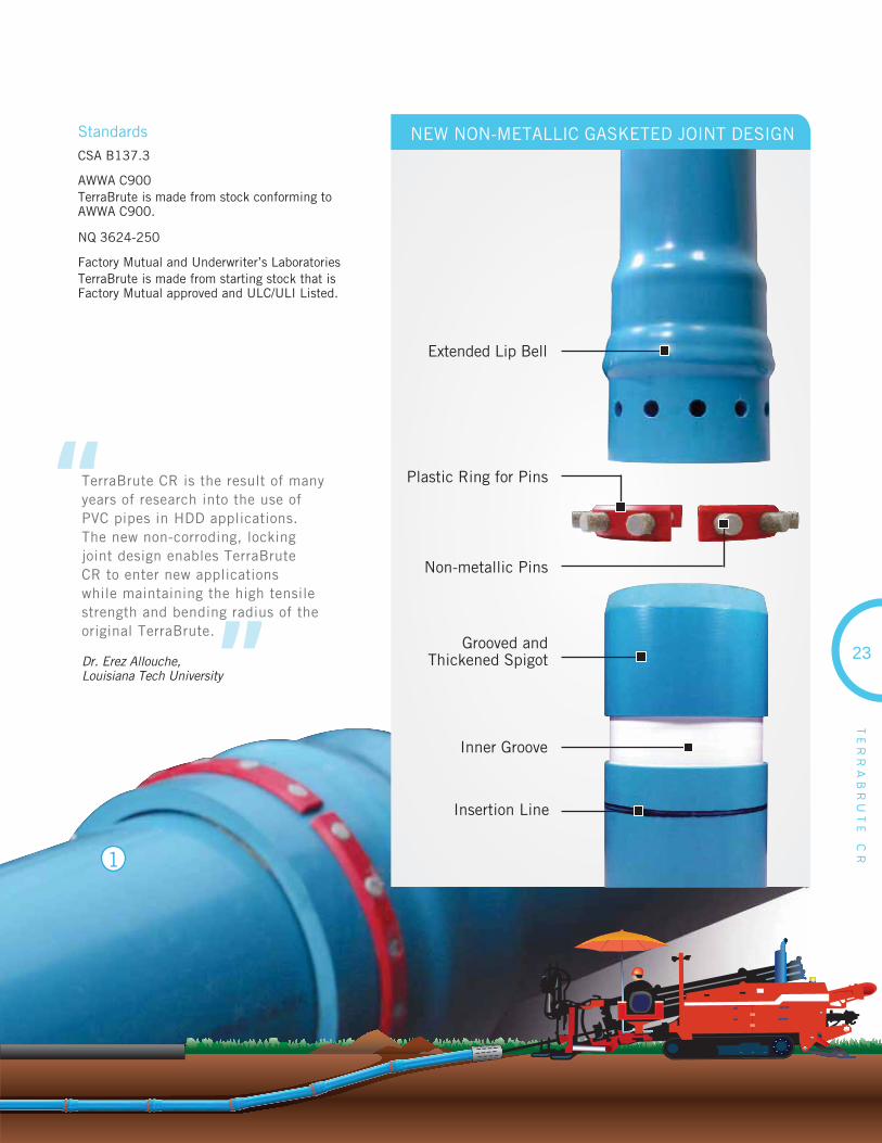
TerraBrute CR’s patented non-metallic “ring-and-pin” gasketed jointdesign outperforms all other restrained PVC pipe joints on the market, providing more than twice the pull strength of other HDD systems – up to 120,000 lbs. for 300mm / 12” pipe. Unlike competing square-shoulder designs, TerraBrute CR’s rounded bell shoulders slide by roots, rocks and other debris that can protrude into the borehole. And unlike HDPE, TerraBrute CR requires no relaxation time before installation of fi ttingsor services.
1
2
3
Corrosion ResistantThe new, non-metallic, “ring-and-pin” confi guration of TerraBrute CR PVC pressure pipe offers complete corrosion resistance. The external “ring” is designed as two half rings for ease of installation and comes complete with the “pins” ready for insertion, creating a strong, locking joint.
Proven PerformanceWith a 235 psi pressure class, TerraBrute CR delivers the superior strength and corrosion resistance you’ve come to expect from our Blue Brute pressure pipe, along with the ability to absorb the underground shear and fl exural stresses that occur in buried applications.
Proven CompatibilityTerraBrute CR trenchless PVC pipe is designed for total compatibility with your municipal system. Connections can be made with standard PVC CIOD fi ttings, direct tapped couplings or standard service saddles. Repair and handling techniques are the same as for any AWWA PVC pressure pipe.
Proven Joining SystemBased on our gasketed bell and spigot design, proven through years of service in the fi eld, the TerraBrute CR joint is rated higher than the pressure rating of the pipe. And unlike competing coupling joints, the TerraBrute CR joint has been specially engineered to deliver the highest pull strength safety factors in the industry for HDD applications.
Fast and Easy Joint AssemblyBecause pipe segments can be assembled during pullback operations, pipe stringing can be eliminated. Assembly time for a 300mm / 12” TerraBrute CR joint is typically less than fi ve minutes.
4
5
ADVANTAGES
B137.3 3624-250
23
TE
RR
AB
RU
TE
C
R
StandardsCSA B137.3
AWWA C900TerraBrute is made from stock conforming toAWWA C900.
NQ 3624-250
Factory Mutual and Underwriter’s LaboratoriesTerraBrute is made from starting stock that is Factory Mutual approved and ULC/ULI Listed.
“
”
TerraBrute CR is the result of many years of research into the use of PVC pipes in HDD applications. The new non-corroding, locking joint design enables TerraBrute CR to enter new applications while maintaining the high tensile strength and bending radius of the original TerraBrute.
Dr. Erez Allouche,Louisiana Tech University
1
NEW NON-METALLIC GASKETED JOINT DESIGN
Inner Groove
Grooved and Thickened Spigot
Non-metallic Pins
Extended Lip Bell
Plastic Ring for Pins
Insertion Line
TE
RR
AB
RU
TE
C
R
BRIDGE CROSSINGSTerraBrute CR’s unique “new non-metallic ring-and-pin” joint design provides for easy installation innon-HDD applications where traditional butt fusion techniques would be diffi cult – such as this span of suspended pressure pipe installed beneath a busy roadway bridge.
URBAN CENTERSBecause TerraBrute CR can be assembled segmentally just before entering the borehole, projects take up less space in restricted urban areas, compared to the long strings of pipe typical with HDPE installations.
ROAD CROSSINGSTerraBrute CR is ideally suited for short drilling projects where existing structures cannot be disturbed – such as under busy highways, roads and intersections where you connect to PVC pipes.
APPLICATIONS
10” (250mm) TerraBrute CR
Pipe Stop8” (200mm)
TerraBrute CR Pipe Stop
Nominal Size Maximum Allowable Pulling Force
mm Inches kN Lbs.
100 4 50 11200
150 6 110 24700
200 8 115 25800
250 10 187 42100
300 12 275 61800
GENERALPVC pipe used for horizontal directional drilling (HDD) or other trenchless installation methods shall be manufactured with a cast iron outside diameter (CIOD) and shall be made with starting stock certifi ed to CSA B137.3 for 100mm - 300mm (4” - 12”) diameters. Pipe will meet the requirements of AWWA C900, must be Factory Mutual approved, and listed by ULC and ULI.
MAXIMUM ALLOWABLE PULLING FORCEThe maximum allowable pulling force shall be the ultimate tensile capacity of the piping system divided by a safety factorof 2, as shown in the table below.
JOINT DESIGNPVC pipe must be manufactured with an integral bell, and must have removable gaskets to allow the use of oil-resistant (nitrile) gaskets in contaminated soils.
SHORT FORM SPECIFICATIONS
099023
24
099024
TE
RR
AB
RU
TE
C
R
25
TerraBrute CR Pipe & Dimensions
NominalDiameter Product
Code
PressureClass/Rating
(2:1 safety factor)
Max Outside Diameter(Bell OD)
Avg Internal Diameter
in mm psi in mm in mm
4 100 070258 305 6.49 165 4.09 104
6 150 070259 305 9.06 230 5.87 149
8 200 070260 235 11.33 288 8.03 204
10 250 070261 235 14.00 355 9.84 250
12 300 070262 235 16.36 416 11.69 297
TerraBrute CR’s larger internal diameters, compared to HDPE pipe, provide the samehydraulic performance usually with one size smaller pipe, saving on material costs.
Nominal Size Laying Lengths
Inches mm Feet/Inches m
4 100 19’ 10” 6.04
6 150 19’ 9” 6.03
8 200 19’ 9” 6.01
10 250 19’ 9” 6.01
12 300 19’ 9” 6.01
Due to the extended bell confi guration, TerraBrute has slightly shorter laying lengththan standard Blue Brute pipe.
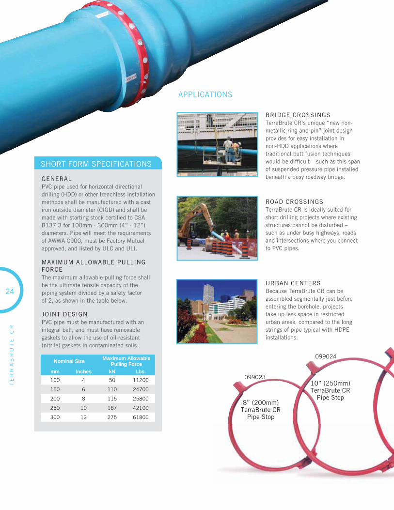
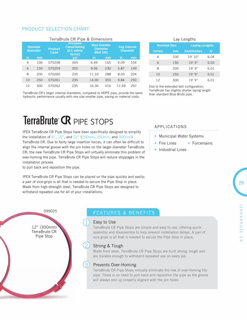
IPEX TerraBrute CR Pipe Stops have been specifi cally designed to simplify the installation of 8”, 10”, and 12” (200mm, 250mm, and 300mm)TerraBrute CR. Due to fairly large insertion forces, it can often be diffi cult to align the internal groove with the pin holes on the larger diameter TerraBrute CR; the new TerraBrute CR Pipe Stops will virtually eliminate this problem of over-homing the pipe. TerraBrute CR Pipe Stops will reduce stoppages in the installation processto pull back and reposition the pipe.
IPEX TerraBrute CR Pipe Stops can be placed on the pipe quickly and easily; a pair of vice-grips is all that is needed to secure the Pipe Stop in place. Made from high-strength steel, TerraBrute CR Pipe Stops are designed to withstand repeated use for all of your installations.
• Municipal Water Systems
• Fire Lines
• Industrial Lines
• Forcemains
APPLICATIONS
PRODUCT SELECTION CHART
12” (300mm)TerraBrute CR
Pipe Stop
PIPE STOPS
1
2
3
FEATURES & BENEFITS
Easy to UseTerraBrute CR Pipe Stops are simple and easy to use, offering quick assembly and disassembly to help prevent installation delays. A pair of vice grips is all that is needed to secure the Pipe Stop in place.
Strong & ToughMade from steel, TerraBrute CR Pipe Stops are built strong, tough and are durable enough to withstand repeated use on every job.
Prevents Over-HomingTerraBrute CR Pipe Stops virtually eliminate the risk of over-homing the pipe. There is no need to pull back and reposition the pipe as the groove will always end up properly aligned with the pin holes.
099025
Lay Lengths
ADVANTAGES
High Pressure CapacityCycleTough systems have a 2:1 safety factor for long-term pressures, and over 3.2:1 for temporary surges.
Toughness Engineered CycleTough fi ttings are engineered for versatility and reliability. Their unique design features extra material added for reinforcement to withstand the stresses imposed by tough irrigation and forcemain applications.
Iron Pipe Size Outside Diameter (IPSOD)CycleTough systems are made with an IPSOD, which is the same outside diameter confi guration as schedule piping and most steel process piping.
Bottle-tight Joints, Removable GasketsIPEX’s patented gasket system not only withstands the rated system pressure, but also withstands full vacuum pressures. The removable gasket system allows special oil-resistant (nitrile) gaskets to be easily installed when working in contaminated soils.
Third-party Certifi cationAll CycleTough systems are certifi ed to CSA B137.3.Third-party certifi cation verifi es a system will perform as expected, meeting all applicable standards.
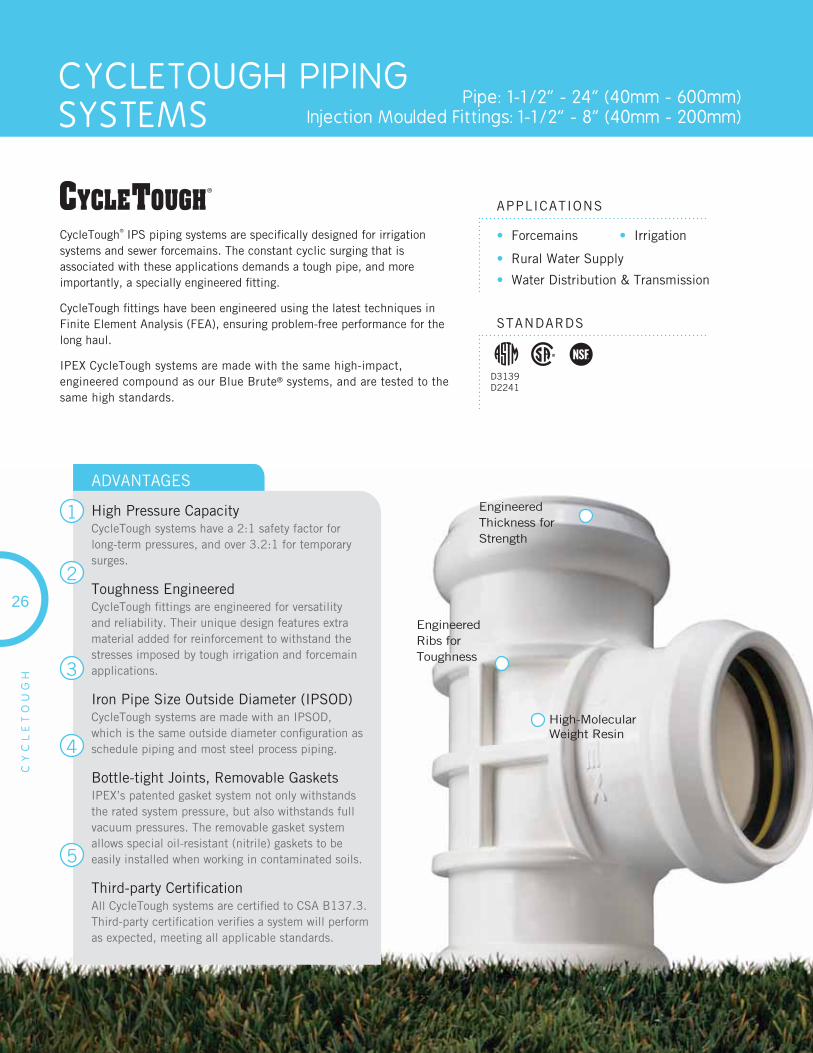
CYCLETOUGH PIPING SYSTEMS
Pipe: 1-1/2” - 24” (40mm - 600mm)Injection Moulded Fittings: 1-1/2” - 8” (40mm - 200mm)
26
CY
CL
ET
OU
GH
• Forcemains • Irrigation
• Rural Water Supply
• Water Distribution & Transmission
APPLICATIONS
STANDARDS
CycleTough® IPS piping systems are specifi cally designed for irrigation systems and sewer forcemains. The constant cyclic surging that isassociated with these applications demands a tough pipe, and more importantly, a specially engineered fi tting.
CycleTough fi ttings have been engineered using the latest techniques in Finite Element Analysis (FEA), ensuring problem-free performance for the long haul.
IPEX CycleTough systems are made with the same high-impact, engineered compound as our Blue Brute® systems, and are tested to the same high standards.
1
2
3
4
5
High-Molecular Weight Resin
Engineered Thickness for Strength
Engineered Ribs for Toughness
D3139D2241
27
CY
CL
ET
OU
GH
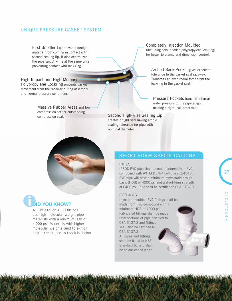
UNIQUE PRESSURE GASKET SYSTEM
i
Pressure Pockets transmit internal water pressure to the pipe spigot making a tight leak-proof seal.
Second High-Rise Sealing Lipcreates a tight seal having ample sealing tolerance for pipe with nominal diameter.
First Smaller Lip prevents foreign material from coming in contact with second sealing lip. It also centralizes the pipe spigot while at the same time preventing contact with lock ring.
Arched Back Pocket gives excellent tolerance to the gasket seal raceway. Transmits an even radial force from the lockring to the gasket seat.
Massive Rubber Areas and low compression set for outstanding compression seal.
Completely Injection Moulded(including colour coded polypropylene lockring) for better tolerance and dimension control.
DID YOU KNOW?All CycleTough 4000 fittings use high-molecular-weight pipe materials with a minimum HDB of 4,000 psi. Materials with higher molecular weights tend to exhibit better resistance to crack initiation.
High-Impact and High-MemoryPolypropylene Lockring prevents gasket movement from the raceway during assembly and normal pressure conditions.
SHORT FORM SPECIFICATIONS
PIPESIPSOD PVC pipe shall be manufactured from PVC compound with ASTM D1784 cell class 12454B. PVC pipe will have a minimum hydrostatic design basis (HDB) of 4000 psi and a short-term strength of 6400 psi. Pipe shall be certifi ed to CSA B137.3.
FITTINGSInjection-moulded PVC fi ttings shall be made from PVC compound with a minimum HDB of 4000 psi. Fabricated fi ttings shall be made from sections of pipe certifi ed to CSA B137.3 and fi ttings shall also be certifi ed to CSA B137.3.All pipes and fi ttings shall be listed to NSF Standard 61 and shall be colour-coded white.

CY
CL
ET
OU
GH
28
WHY CYCLETOUGH FORCYCLIC APPLICATIONS?
Current research shows that PVC pipe has a virtually unlimited lifespan under some of the most demanding cyclic conditions. While thepipe is inherently ‘CycleTough’, fi ttings are subject to a variety of different stresses that can easily damage a conventionally designed product. CycleTough injection moulded fi ttings have been specifi cally designed for high-pressure cyclic applications using the latest engineering methods, and extensive computer modeling. While other PVC fi ttings may not be up to the task, CycleTough fi ttings were designed for it, with the right amount of material in the right places. That is why CycleTough fi ttings look different from other PVC fi ttings on the market: CycleTough fi ttings are made for tough applications.
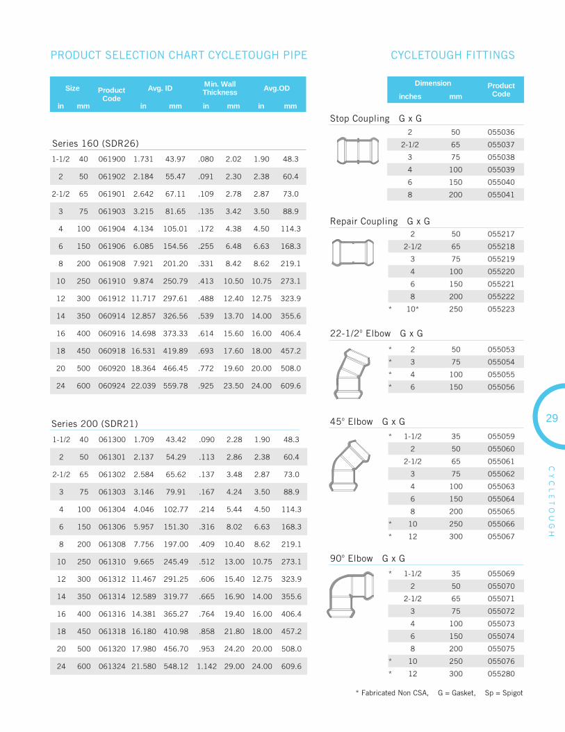
PRODUCT SELECTION CHART CYCLETOUGH PIPE
Size ProductCode
Avg. ID Min. WallThickness Avg.OD
in mm in mm in mm in mm
4 100 061204 4.278 108.41 .109 2.78 4.50 114.3
6 150 061206 6.282 159.57 .162 4.12 6.63 168.3
8 200 061208 8.180 207.77 .209 5.32 8.62 219.1
10 250 061210 10.194 258.93 .262 6.66 10.75 273.1
12 300 061212 12.093 307.15 .311 7.90 12.75 323.9
14 350 060214 13.277 337.24 .341 8.66 14.00 355.6
16 400 060216 15.174 385.41 .390 9.90 16.00 406.4
18 450 060218 17.074 433.67 .437 11.10 18.00 457.2
20 500 060220 18.985 481.71 .488 12.40 20.00 508.0
24 600 060224 22.756 578.01 .587 14.90 24.00 609.6
4 100 061104 4.208 106.88 .138 3.50 4.50 114.3
6 150 061106 6.194 157.32 .204 5.18 6.63 168.3
8 200 061108 8.063 204.80 .265 6.72 8.62 219.1
10 250 061110 10.049 255.24 .331 8.40 10.75 273.1
12 300 061112 11.921 302.78 .392 9.96 12.75 323.9
14 350 060114 13.090 332.49 .429 10.90 14.00 355.6
16 400 060116 14.957 379.90 .492 12.50 16.00 406.4
18 450 060118 16.823 427.31 .555 14.10 18.00 457.2
20 500 060120 18.698 474.93 .614 15.60 20.00 508.0
24 600 060124 22.431 569.74 .740 18.80 24.00 609.6
Series 125 (SDR32.5)
Series 100 (SDR41)
For more information on how these ratings are calculated, please refer to Volume I: Pressure Piping Systems Design Technical Manual
Pressure Ratings and Burst PressuresSize
RangeDimension
RatioPressure
Rating (psi)Long TermRating (psi)
40 – 600 21 200 200
40 – 600 26 160 160
75 – 600 32.5 125 125
100 – 600 41 100 100
PRESSURE RATINGS
CY
CL
ET
OU
GH
29
PRODUCT SELECTION CHART CYCLETOUGH PIPE CYCLETOUGH FITTINGS
Size ProductCode
Avg. ID Min. WallThickness Avg.OD
in mm in mm in mm in mm
2 50 055036
2-1/2 65 055037
3 75 055038
4 100 055039
6 150 055040
8 200 055041
2 50 055217
2-1/2 65 055218
3 75 055219
4 100 055220
6 150 055221
8 200 055222
* 10* 250 055223
* 2 50 055053
* 3 75 055054
* 4 100 055055
* 6 150 055056
* 1-1/2 35 055059
2 50 055060
2-1/2 65 055061
3 75 055062
4 100 055063
6 150 055064
8 200 055065
* 10 250 055066
* 12 300 055067
* 1-1/2 35 055069
2 50 055070
2-1/2 65 055071
3 75 055072
4 100 055073
6 150 055074
8 200 055075
* 10 250 055076
* 12 300 055280
Stop Coupling G x G
Repair Coupling G x G
22-1/2o Elbow G x G
45o Elbow G x G
90o Elbow G x G
* Fabricated Non CSA, G = Gasket, Sp = Spigot
Series 200 (SDR21)
1-1/2 40 061900 1.731 43.97 .080 2.02 1.90 48.3
2 50 061902 2.184 55.47 .091 2.30 2.38 60.4
2-1/2 65 061901 2.642 67.11 .109 2.78 2.87 73.0
3 75 061903 3.215 81.65 .135 3.42 3.50 88.9
4 100 061904 4.134 105.01 .172 4.38 4.50 114.3
6 150 061906 6.085 154.56 .255 6.48 6.63 168.3
8 200 061908 7.921 201.20 .331 8.42 8.62 219.1
10 250 061910 9.874 250.79 .413 10.50 10.75 273.1
12 300 061912 11.717 297.61 .488 12.40 12.75 323.9
14 350 060914 12.857 326.56 .539 13.70 14.00 355.6
16 400 060916 14.698 373.33 .614 15.60 16.00 406.4
18 450 060918 16.531 419.89 .693 17.60 18.00 457.2
20 500 060920 18.364 466.45 .772 19.60 20.00 508.0
24 600 060924 22.039 559.78 .925 23.50 24.00 609.6
Series 160 (SDR26)
1-1/2 40 061300 1.709 43.42 .090 2.28 1.90 48.3
2 50 061301 2.137 54.29 .113 2.86 2.38 60.4
2-1/2 65 061302 2.584 65.62 .137 3.48 2.87 73.0
3 75 061303 3.146 79.91 .167 4.24 3.50 88.9
4 100 061304 4.046 102.77 .214 5.44 4.50 114.3
6 150 061306 5.957 151.30 .316 8.02 6.63 168.3
8 200 061308 7.756 197.00 .409 10.40 8.62 219.1
10 250 061310 9.665 245.49 .512 13.00 10.75 273.1
12 300 061312 11.467 291.25 .606 15.40 12.75 323.9
14 350 061314 12.589 319.77 .665 16.90 14.00 355.6
16 400 061316 14.381 365.27 .764 19.40 16.00 406.4
18 450 061318 16.180 410.98 .858 21.80 18.00 457.2
20 500 061320 17.980 456.70 .953 24.20 20.00 508.0
24 600 061324 21.580 548.12 1.142 29.00 24.00 609.6
Dimension ProductCodeinches mm

CY
CL
ET
OU
GH
30
Tee G x G x G Reducing Tee G x G x G
Male Adapter G x Male Pipe Thread
Spigot Adapter G x Sp
Wye G x G x G
Cross G x G x G
Increaser Bushing G x Sp
* 1-12 35 055227
2 50 055228
2-1/2 65 055229
3 75 055230
4 100 055231
6 150 055232
8 200 055233
* 10 250 055234
* 12 300 055281
* 3 75 055291
* 4 100 055293
* 6 150 055290
* 8 x 6 200 x 150 055294
* 8 200 055298
* 12 x 6 300 x 150 055297
* 12 x 8 300 x 200 055299
* 12 300 055296
* 2 50 055045
* 2-1/2 65 055046
* 3 75 055047
4 100 055048
6 150 055049
1-1/2 x 2 35 x 50 055129
2 x 2-1/2 50 x 65 055130
2 x 3 50 x 75 055131
2 x 4 50 x 100 055133
* 2 x 6 50 x 150 049280
2-1/2 x 3 65 x 75 055132
2-1/2 x 4 65 x 100 055134
2-1/2 x 6 65 x 150 055136
3 x 4 75 x 100 055135
3 x 6 75 x 150 055137
4 x 6 100 x 150 055138
4 x 8 100 x 200 055139
6 x 8 150 x 200 055140
2 x 1-1/2 50 x 35 055151
2-1/2 x 2 65 x 50 055153
3 x 1-1/2 75 x 35 055154
3 x 2 75 x 50 055155
3 x 2-1/2 75 x 65 055156
4 x 2 100 x 50 055157
4 x 2-1/2 100 x 65 055158
4 x 3 100 x 75 055159
6 x 2 150 x 50 055161
6 x 2-1/2 150 x 65 055162
6 x 3 150 x 75 055163
6 x 4 150 x 100 055164
8 x 2 200 x 50 055165
8 x 3 200 x 75 055166
8 x 4 200 x 100 055167
8 x 6 200 x 150 055168
1-1/2 35 055099
2 50 055100
2-1/2 65 055101
3 75 055102
* 4 100 055103
* 6 150 055104
1-1/2 35 055028
2 50 055029
2-1/2 65 055030
3 75 055031
* 4 100 055032
* 6 150 055033
* Fabricated Non CSA, G = Gasket, Sp = Spigot† Reduced using Solvent Welded Threading Reducer Bushings
PRODUCT SELECTION CHART CYCLETOUGH FITTINGS
Dimension ProductCodeinches mm
Dimension ProductCodeinches mm
CY
CL
ET
OU
GH
31
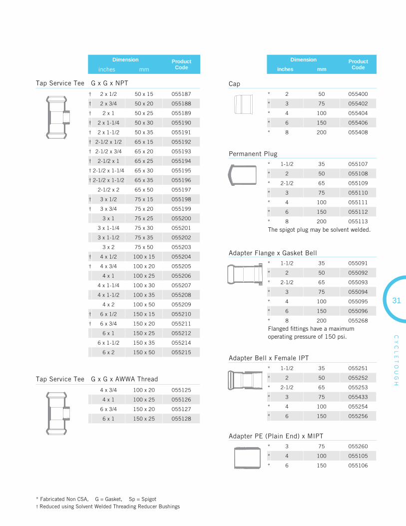
Tap Service Tee G x G x NPT
† 2 x 1/2 50 x 15 055187
† 2 x 3/4 50 x 20 055188
† 2 x 1 50 x 25 055189
† 2 x 1-1/4 50 x 30 055190
† 2 x 1-1/2 50 x 35 055191
† 2-1/2 x 1/2 65 x 15 055192
† 2-1/2 x 3/4 65 x 20 055193
† 2-1/2 x 1 65 x 25 055194
† 2-1/2 x 1-1/4 65 x 30 055195
† 2-1/2 x 1-1/2 65 x 35 055196
2-1/2 x 2 65 x 50 055197
† 3 x 1/2 75 x 15 055198
† 3 x 3/4 75 x 20 055199
3 x 1 75 x 25 055200
3 x 1-1/4 75 x 30 055201
3 x 1-1/2 75 x 35 055202
3 x 2 75 x 50 055203
† 4 x 1/2 100 x 15 055204
† 4 x 3/4 100 x 20 055205
4 x 1 100 x 25 055206
4 x 1-1/4 100 x 30 055207
4 x 1-1/2 100 x 35 055208
4 x 2 100 x 50 055209
† 6 x 1/2 150 x 15 055210
† 6 x 3/4 150 x 20 055211
6 x 1 150 x 25 055212
6 x 1-1/2 150 x 35 055214
6 x 2 150 x 50 055215
* 2 50 055400
* 3 75 055402
* 4 100 055404
* 6 150 055406
* 8 200 055408
* Fabricated Non CSA, G = Gasket, Sp = Spigot† Reduced using Solvent Welded Threading Reducer Bushings
Tap Service Tee G x G x AWWA Thread
4 x 3/4 100 x 20 055125
4 x 1 100 x 25 055126
6 x 3/4 150 x 20 055127
6 x 1 150 x 25 055128
Cap
* 1-1/2 35 055107
* 2 50 055108
* 2-1/2 65 055109
* 3 75 055110
* 4 100 055111
* 6 150 055112
* 8 200 055113
Permanent Plug
Dimension ProductCodeinches mm
Dimension ProductCodeinches mm
The spigot plug may be solvent welded.
* 1-1/2 35 055091
* 2 50 055092
* 2-1/2 65 055093
* 3 75 055094
* 4 100 055095
* 6 150 055096
* 8 200 055268
Adapter Flange x Gasket Bell
Flanged fi ttings have a maximum operating pressure of 150 psi.
* 1-1/2 35 055251
* 2 50 055252
* 2-1/2 65 055253
* 3 75 055433
* 4 100 055254
* 6 150 055256
Adapter Bell x Female IPT
* 3 75 055260
* 4 100 055105
* 6 150 055106
Adapter PE (Plain End) x MIPT
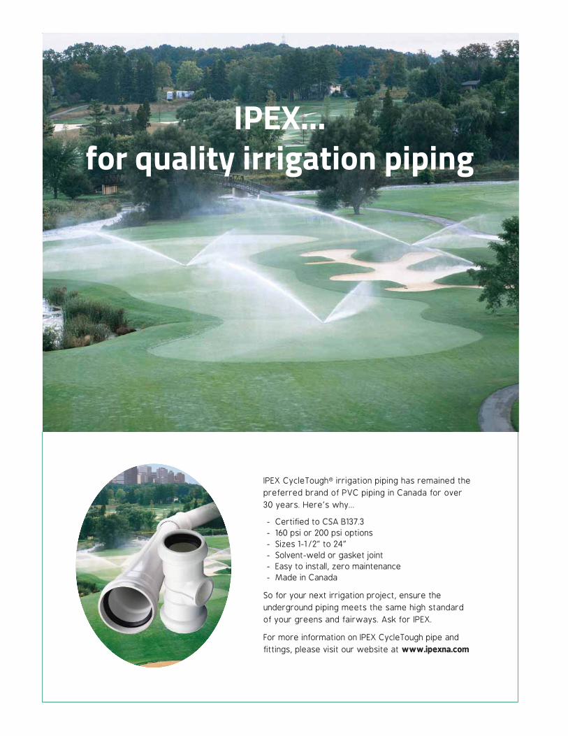
IPEX CycleTough® irrigation piping has remained the preferred brand of PVC piping in Canada for over 30 years. Here’s why...
- Certified to CSA B137.3- 160 psi or 200 psi options- Sizes 1-1/2” to 24”- Solvent-weld or gasket joint- Easy to install, zero maintenance- Made in Canada
So for your next irrigation project, ensure the underground piping meets the same high standard of your greens and fairways. Ask for IPEX.
For more information on IPEX CycleTough pipe and fittings, please visit our website at www.ipexna.com
IPEX…for quality irrigation piping

PRESSURE PIPE & FITTINGS
Blue Brute Piping Systems 6
Blue Brute Fitting Systems 10
Bionax PVCO Pressure Piping Systems 14
IPEX Centurion Piping Systems 16
IPEX Fusible 24
TerraBrute CR 26
CycleTough Piping Systems 30
As copper prices continue to rise, cities across North America are turning
to cost effective alternatives for their water service lines that connect
municipal watermains to buildings. IPEX provides a range of options from
polyethylene, PEX and composite tubing for water service lines which are
immune to corrosion and mineral buildup.
All IPEX water service systems are CSA and NSF certifi ed and conform to
AWWA standards. They are backed by the quality and service you’ve come
to expect from IPEX.
WATER SERVICESYSTEMS
Blue904 PEX Water Service Tubing 34
Q-Line Water Service Tubing 36
Gold901 Water Service Tubing 38
Philmac 3G Compression Fittings 40

BLUE904 PEXWATER SERVICE TUBING 3/4” - 2” (20mm - 50mm)
BL
UE
90
4
• Water Service Tubing
• Municipal Watermains
APPLICATIONS
STANDARDS
As copper prices continue to rise, cities across North America are turning to cost effective alternatives for their water service lines that connect municipal watermains to buildings.
Blue904® is fully certifi ed, lightweight and fl exible PEX water service tubing. Installation friendly, Blue904 will resist corrosion, maximizing water fl ow over the lifetime of the system. Made with a copper tube size (CTS) OD (SDR 9), Blue904 works with standard compression fi ttings and is available in 3/4”, 1”, 1-1/4”, 1-1/2” & 2” (20mm, 25mm, 32mm, 40mm & 50mm) sizes.
1
2
3
4
5
Standard 14 & 61ASTM F876ASTM F877
B137.5
ADVANTAGES
Easy Installation No special tools required.
Corrosion Resistant for Long Life Blue904 will resist the effects of chlorine and scaling and will not corrode in soil. It is also freeze resistant due to its low thermal conductivity when compared to copper tubing.
Lightweight and Flexible for Easy Handling
Jobsite SafeUnlike copper tubing, PEX tubing has no scrap value,eliminating the threat of jobsite theft common with copper.As a result, no special storage precautions are necessary.
Packaging and MarkingsBlue904 is available in 100 ft (30m) and 300 ft (90m) coils and is packaged in boxes for UV protection and portability.Each coil has footage markings to assist during installation and is identifi ed with product name, size, certifi cations and manufacturing date.
ss
34

35
BL
UE
90
4
PRESSURE RATING
Sizes Pressure Rating
3/4” - 2”(20mm - 50mm)
160 psi @ 73ºF (1100 kPa @ 23ºC)
100 psi @ 180ºF (690 kPa @ 82ºC)
PRODUCT SELECTION CHART
Nominal Size I.D. Min. Bend Radius ProductCode
Coil Length
in mm in mm in mm feet m
3/4 20 0.681 17.3 4.5 114 117001 300 90
3/4 20 0.681 17.3 4.5 114 117002 100 30
1 25 0.875 22.2 6.0 152 117003 300 90
1 25 0.875 22.2 6.0 152 117004 100 30
1-1/2 40 1.241 31.5 9.0 229 117006 100 30
2 50 1.625 41.3 12.0 305 117007 100 30
RISING COPPER COSTS ARE INCREASING SITE THEFT ...
Why not PEX it?
Blue904®
PEX Water Service Tubing
>> Easy Installation
>> Corrosion Resistant
>> Lightweight & Flexible
>> Jobsite Safe
>> Fully Certified
For more information,contact us at 1-866-473-9462or visit us at ipexna.com
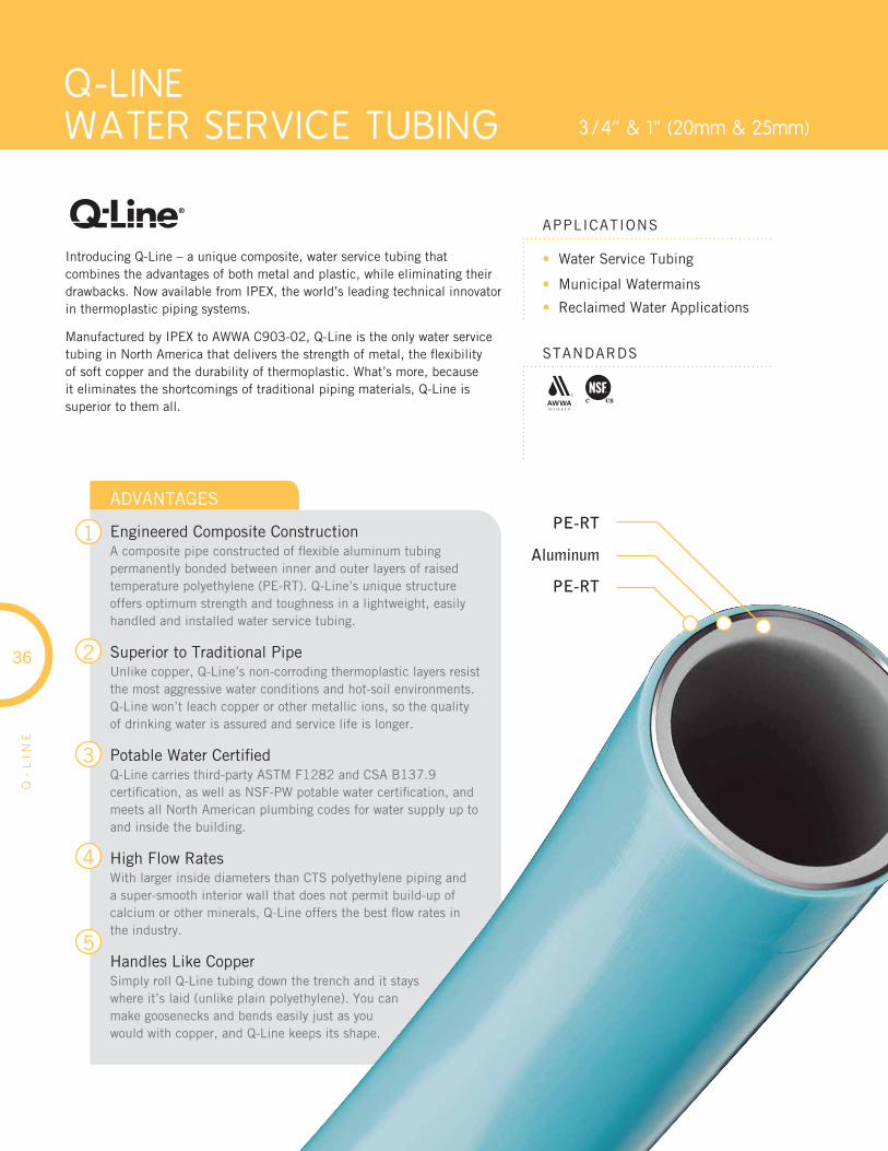
Q-LINEWATER SERVICE TUBING 3/4” & 1” (20mm & 25mm)
Q-
LIN
E
• Water Service Tubing
• Municipal Watermains
• Reclaimed Water Applications
APPLICATIONS
STANDARDS
Introducing Q-Line – a unique composite, water service tubing that combines the advantages of both metal and plastic, while eliminating their drawbacks. Now available from IPEX, the world’s leading technical innovator in thermoplastic piping systems.
Manufactured by IPEX to AWWA C903-02, Q-Line is the only water service tubing in North America that delivers the strength of metal, the fl exibility of soft copper and the durability of thermoplastic. What’s more, because it eliminates the shortcomings of traditional piping materials, Q-Line is superior to them all.
1
2
3
4
5
ADVANTAGES
Engineered Composite ConstructionA composite pipe constructed of fl exible aluminum tubing permanently bonded between inner and outer layers of raised temperature polyethylene (PE-RT). Q-Line’s unique structure offers optimum strength and toughness in a lightweight, easily handled and installed water service tubing.
Superior to Traditional Pipe Unlike copper, Q-Line’s non-corroding thermoplastic layers resist the most aggressive water conditions and hot-soil environments. Q-Line won’t leach copper or other metallic ions, so the quality of drinking water is assured and service life is longer.
Potable Water Certifi edQ-Line carries third-party ASTM F1282 and CSA B137.9 certifi cation, as well as NSF-PW potable water certifi cation, and meets all North American plumbing codes for water supply up toand inside the building.
High Flow RatesWith larger inside diameters than CTS polyethylene piping and a super-smooth interior wall that does not permit build-up of calcium or other minerals, Q-Line offers the best fl ow rates in the industry.
Handles Like Copper Simply roll Q-Line tubing down the trench and it stays where it’s laid (unlike plain polyethylene). You can make goosenecks and bends easily just as you would with copper, and Q-Line keeps its shape.
PE-RT
Aluminum
PE-RT
36

37
CODES AND STANDARDS
Q-Line water service tubing is manufactured to AWWA C903, ASTM F1282 and CSA B137.9, and meets NSF-PW potable water requirements as well as requirements of the followingnational codes.
• National Plumbing code of Canada
• Uniform Plumbing Code
• International Plumbing Code
• International Residential Code
• National Standard Plumbing Code
• SBCCI Standard Plumbing Code
MORE ADVANTAGES ...
Built-in Permeation BarrierQ-Line composite water service tubing has been successfully tested against the most aggressive contaminants, like termiticides.
Zero Scrap Value Because Q-Line’s metallic core is permanently locked between layers of polyethylene, it has zero scrap metal value. So unlike copper and other valuable metals which are continually disappearing due to theft, Q-Line is more likely to stay on the job site where it’s needed.
SHORT FORM SPECIFICATIONS
TUBINGWater service tubing shall be composite PE-AL-PE tubing manufactured in accordance with the requirements of AWWA C903 and certifi ed to CSA B137.9 and ASTM F1282. It shall have a long term pressure rating of 1380kPa at 23ºC (200 psi at 73ºF) and 690kPa at 82ºC (100 psi at 180ºF). The pipe shall be third-party tested and certifi ed to comply with NSF-PW potable water and NSF CL-TD chlorine resistance requirements. The service tubing shall be colour coded light blue as manufactured by IPEX under the trade name “Q-Line” or approved equal.
FITTINGSFittings for composite PE-AL-PE tubing shall be brass water service fi ttings conforming to AWWA C800.
PRODUCT SELECTION CHART
Q-Line Pipes
Municipal Brass Water Service Fittings
* Adapts to any municipal valve with compression end.Note: All brass fi ttings conform to AWWA C800 Standard for Underground Service Line Valves and Fittings.
Description Product Code
3/4” Q-Line x 3/4” Copper Compression, Universal Q-Line Adapter 088083*
1” Q-Line x 1” Copper Compression, Universal Q-Line Adapter 088084*
3/4” Q-Line x 3/4” Male NPT Adapter 088129
1” Q-Line x 1” Male NPT Adapter 088250
3/4” Q-Line Coupling 088131
1” Q-Line Coupling 088251
Q-
LIN
E
Q-Line has unique inside and outside diameters that are different both
from copper and conventionalPE service tubing. Easily installed adapters that allow Q-line to be
used with standard brass fittings are widely available.
ONE OF A KINDNominal Size Product
CodeAvg. ID Min. Wall
Thickness Avg. OD Min. Bending Radius Coil Length
in mm in mm in mm in mm in mm ft m
3/4 20 115001 0.79 20 0.10 2.5 0.98 25 5.0 125 150 45.7
3/4 20 115003 0.79 20 0.10 2.5 0.98 25 5.0 125 1000 305.0
1 25 115004 0.98 25 0.14 3.5 1.26 32 6.3 160 150 45.7
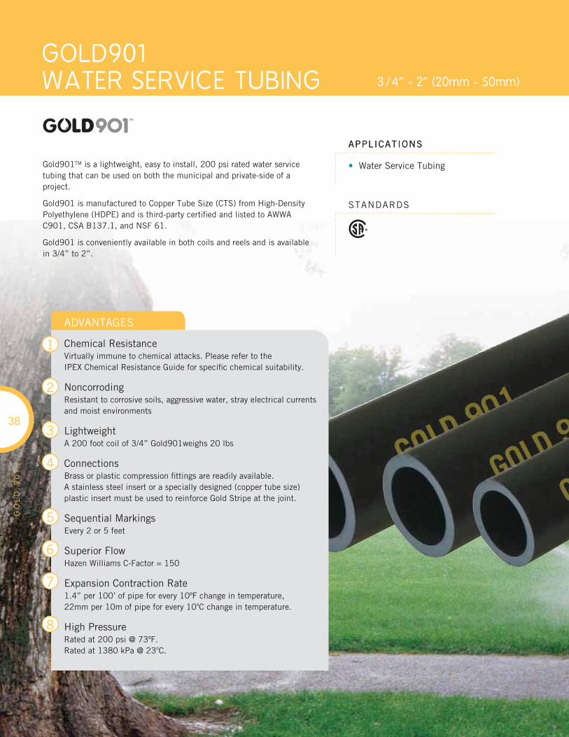
APPLICATIONS
GOLD901 WATER SERVICE TUBING 3/4” - 2” (20mm - 50mm)
• Water Service Tubing
APPLICATIONS
STANDARDS
Gold901TM is a lightweight, easy to install, 200 psi rated water service tubing that can be used on both the municipal and private-side of a project.
Gold901 is manufactured to Copper Tube Size (CTS) from High-Density Polyethylene (HDPE) and is third-party certifi ed and listed to AWWA C901, CSA B137.1, and NSF 61.
Gold901 is conveniently available in both coils and reels and is available in 3/4” to 2”.
GO
LD
90
1
ADVANTAGES
Chemical ResistanceVirtually immune to chemical attacks. Please refer to theIPEX Chemical Resistance Guide for specifi c chemical suitability.
NoncorrodingResistant to corrosive soils, aggressive water, stray electrical currents and moist environments
LightweightA 200 foot coil of 3/4” Gold901weighs 20 lbs
ConnectionsBrass or plastic compression fi ttings are readily available.A stainless steel insert or a specially designed (copper tube size) plastic insert must be used to reinforce Gold Stripe at the joint.
Sequential MarkingsEvery 2 or 5 feet
Superior FlowHazen Williams C-Factor = 150
Expansion Contraction Rate1.4” per 100’ of pipe for every 10ºF change in temperature,22mm per 10m of pipe for every 10oC change in temperature.
High PressureRated at 200 psi @ 73ºF. Rated at 1380 kPa @ 23oC.
38
1
2
3
4
5
6
7
8
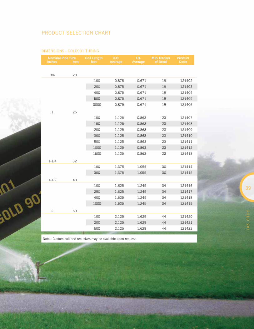
GO
LD
90
1
PRODUCT SELECTION CHART
3/4 20
100 0.875 0.671 19 121402
200 0.875 0.671 19 121403
400 0.875 0.671 19 121404
500 0.875 0.671 19 121405
3000 0.875 0.671 19 121406
Nominal Pipe Size inches mm
Coil Lengthfeet
O.D.Average
I.D.Average
Min. Radiusof Bend
ProductCode
1 25
100 1.125 0.863 23 121407
150 1.125 0.863 23 121408
200 1.125 0.863 23 121409
300 1.125 0.863 23 121410
500 1.125 0.863 23 121411
1000 1.125 0.863 23 121412
1500 1.125 0.863 23 121413
1-1/4 32
100 1.375 1.055 30 121414
300 1.375 1.055 30 121415
1-1/2 40
100 1.625 1.245 34 121416
250 1.625 1.245 34 121417
400 1.625 1.245 34 121418
1000 1.625 1.245 34 121419
2 50
100 2.125 1.629 44 121420
200 2.125 1.629 44 121421
500 2.125 1.629 44 121422
DIMENSIONS - GOLD901 TUBING
39
Note: Custom coil and reel sizes may be available upon request.
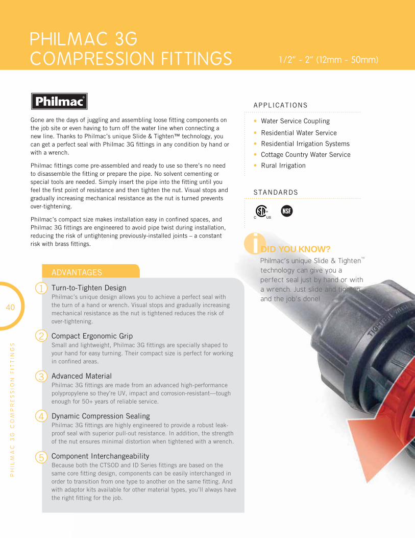
PHILMAC 3G COMPRESSION FITTINGS 1/2” - 2” (12mm - 50mm)
PH
ILM
AC
3G
CO
MP
RE
SS
ION
FIT
TIN
GS
• Water Service Coupling
• Residential Water Service
• Residential Irrigation Systems
• Cottage Country Water Service
• Rural Irrigation
APPLICATIONS
STANDARDS
Gone are the days of juggling and assembling loose fi tting components on the job site or even having to turn off the water line when connecting a new line. Thanks to Philmac’s unique Slide & Tighten™ technology, you can get a perfect seal with Philmac 3G fi ttings in any condition by hand or with a wrench.
Philmac fi ttings come pre-assembled and ready to use so there’s no need to disassemble the fi tting or prepare the pipe. No solvent cementing or special tools are needed. Simply insert the pipe into the fi tting until you feel the fi rst point of resistance and then tighten the nut. Visual stops and gradually increasing mechanical resistance as the nut is turned prevents over-tightening.
Philmac’s compact size makes installation easy in confi ned spaces, and Philmac 3G fi ttings are engineered to avoid pipe twist during installation, reducing the risk of untightening previously-installed joints – a constant risk with brass fi ttings.
1
2
3
4
5
40
ADVANTAGES
Turn-to-Tighten DesignPhilmac’s unique design allows you to achieve a perfect seal with the turn of a hand or wrench. Visual stops and gradually increasing mechanical resistance as the nut is tightened reduces the risk of over-tightening.
Compact Ergonomic GripSmall and lightweight, Philmac 3G fi ttings are specially shaped to your hand for easy turning. Their compact size is perfect for working in confi ned areas.
Advanced MaterialPhilmac 3G fi ttings are made from an advanced high-performance polypropylene so they’re UV, impact and corrosion-resistant—tough enough for 50+ years of reliable service.
Dynamic Compression SealingPhilmac 3G fi ttings are highly engineered to provide a robust leak-proof seal with superior pull-out resistance. In addition, the strength of the nut ensures minimal distortion when tightened with a wrench.
Component InterchangeabilityBecause both the CTSOD and ID Series fi ttings are based on the same core fi tting design, components can be easily interchanged in order to transition from one type to another on the same fi tting. And with adaptor kits available for other material types, you’ll always have the right fi tting for the job.
i DID YOU KNOW?Philmac’s unique Slide & Tighten
TM
technology can give you a perfect seal just by hand or with a wrench. Just slide and tighten, and the job’s done!

41
PH
ILM
AC
3G
CO
MP
RE
SS
ION
FIT
TIN
GS
Philmac 3G Compression Fittings offer the fl exibility to connect to fi ve different types of pipe; three polyethylene pipe types (CTS, ID Series and IPS), Composite and Copper.
There are two dedicated fi ttings, CTS and ID Series, which come preassembled and ready to use. That leaves three others: IPS, XPA, and copper that require a conversion kit. Converting a Philmac fi tting is very simple and can be done in just a few steps.
PHILMAC 3G: CTSOD AND ID SIZES
ID Series1/2” – 2”
OD Fittings3/4” – 2”
CTSOD
ID Series
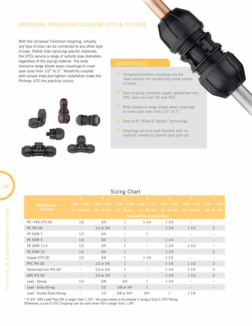
PH
ILM
AC
3G
CO
MP
RE
SS
ION
FIT
TIN
GS
42
Pipe MaterialStandard
A B C D E F G
0.59” - 0.83” 0.83” - 1.06” 1.06” - 1.34” 1.34” - 1.54” 1.54” - 1.69” 1.85” - 1.93” 2.32” - 2.40”
15 - 21 mm 21 - 27 mm 27 - 34 mm 34 - 39 mm 39 - 43 mm 47 - 49 mm 59 - 61 mm
Nominal Pipe Size (inches)
PE / PEX CTS OD 1/2 3/4 1 1-1/4 1-1/2 – –
PE IPS OD – 1/2 or 3/4 1 – 1-1/4 1-1/2 2
PE SIDR 7 1/2 3/4 – 1 – – –
PE SIDR 9 1/2 3/4 1 – 1-1/4 – –
PE SIDR 11.5 1/2 3/4 1 – 1-1/4 1-1/2 –
PE SIDR 15 1/2 3/4 1 – 1-1/4 – 2
Copper CTS OD 1/2 3/4 1 1 1/4 1-1/2 – –
PVC IPS OD – 1/2 or 3/4 1 – 1-1/4 1-1/2 2
Galvanized Iron IPS OD – 1/2 or 3/4 1 – 1-1/4 1-1/2 2
ABS IPS OD – 1/2 or 3/4 1 – 1-1/4 1-1/2 2
Lead - Strong 1/2 5/8 3/4 1 1-1/4 – –
Lead - Extra Strong – 1/2 5/8 or 3/4 1 – – –
Lead - Double Extra Strong – 1/2 5/8 or 3/4* 3/4* 1 1 1/4 –
* If 3/4” XXS Lead Pipe OD is larger than 1.34”, the pipe needs to be shaved if using a Size C UTC fi tting.Otherwise, a size D UTC Coupling can be used when OD is larger than 1.34”.
ADVANTAGES
✓ Universal transition couplings are theideal solution for connecting a wide varietyof pipes.
✓ One coupling connects copper, galvanized iron, PVC, lead and even PE and PEX.
✓ Wide tolerance range allows seven couplingsto cover pipe sizes from 1/2” to 2”.
✓ Easy to fi t “Slide & Tighten” technology.
✓ Couplings are end-load resistant with no restraint needed to prevent pipe pull-out.
UNIVERSAL TRANSITION COUPLING (UTC) & FITTINGS
With the Universal Transition Coupling, virtually any type of pipe can be connected to any other type of pipe. Rather than servicing specifi c materials, the UTCs service a range of outside pipe diameters, regardless of the piping material. The wide tolerance range allows seven couplings to cover pipe sizes from 1/2” to 2”. Versatility coupled with simple slide-and-tighten installation make the Philmac UTC the practical choice.
Sizing Chart
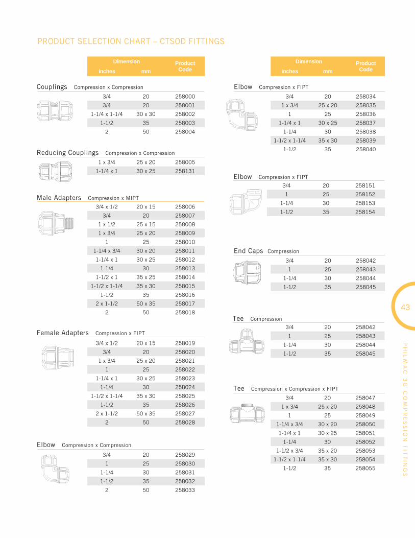
PH
ILM
AC
3G
CO
MP
RE
SS
ION
FIT
TIN
GS
43
PRODUCT SELECTION CHART – CTSOD FITTINGS
3/4 20 258000
3/4 20 258001
1-1/4 x 1-1/4 30 x 30 258002
1-1/2 35 258003
2 50 258004
Couplings Compression x Compression
Elbow Compression x Compression
Elbow Compression x FIPT
Elbow Compression x FIPT
End Caps Compression
Tee Compression
Tee Compression x Compression x FIPT
Reducing Couplings Compression x Compression
Male Adapters Compression x MIPT
Female Adapters Compression x FIPT
1 x 3/4 25 x 20 258005
1-1/4 x 1 30 x 25 258131
3/4 x 1/2 20 x 15 258006
3/4 20 258007
1 x 1/2 25 x 15 258008
1 x 3/4 25 x 20 258009
1 25 258010
1-1/4 x 3/4 30 x 20 258011
1-1/4 x 1 30 x 25 258012
1-1/4 30 258013
1-1/2 x 1 35 x 25 258014
1-1/2 x 1-1/4 35 x 30 258015
1-1/2 35 258016
2 x 1-1/2 50 x 35 258017
2 50 258018
3/4 x 1/2 20 x 15 258019
3/4 20 258020
1 x 3/4 25 x 20 258021
1 25 258022
1-1/4 x 1 30 x 25 258023
1-1/4 30 258024
1-1/2 x 1-1/4 35 x 30 258025
1-1/2 35 258026
2 x 1-1/2 50 x 35 258027
2 50 258028
3/4 20 258029
1 25 258030
1-1/4 30 258031
1-1/2 35 258032
2 50 258033
3/4 20 258034
1 x 3/4 25 x 20 258035
1 25 258036
1-1/4 x 1 30 x 25 258037
1-1/4 30 258038
1-1/2 x 1-1/4 35 x 30 258039
1-1/2 35 258040
3/4 20 258151
1 25 258152
1-1/4 30 258153
1-1/2 35 258154
3/4 20 258042
1 25 258043
1-1/4 30 258044
1-1/2 35 258045
3/4 20 258047
1 x 3/4 25 x 20 258048
1 25 258049
1-1/4 x 3/4 30 x 20 258050
1-1/4 x 1 30 x 25 258051
1-1/4 30 258052
1-1/2 x 3/4 35 x 20 258053
1-1/2 x 1-1/4 35 x 30 258054
1-1/2 35 258055
3/4 20 258042
1 25 258043
1-1/4 30 258044
1-1/2 35 258045
Dimension ProductCodeinches mm
Dimension ProductCodeinches mm

PH
ILM
AC
3G
CO
MP
RE
SS
ION
FIT
TIN
GS
44
PRODUCT SELECTION CHART – ID SERIES FITTINGS
1/2 15 258059
3/4 x 1/2 20 x 15 258065
3/4 20 258060
1 25 258061
1-1/4 30 258062
1-1/2 35 258063
2 50 258064
1/2 15 258066
1/2 x 3/4 15 x 20 258067
3/4 x 1/2 20 x 15 258068
3/4 20 258069
3/4 x 1 20 x 25 258070
1 x 3/4 25 x 20 258071
1 25 258072
1 x 1-1/4 25 x 30 258073
1-1/4 x 1 30 x 25 258074
1-1/4 30 258075
1-1/4 x 1-1/2 30 x 35 258076
1-1/2 35 258077
1-1/2 x 2 35 x 50 258078
2 50 258079
1/2 15 258080
1/2 x 3/4 15 x 20 258081
3/4 20 258082
3/4 x 1 20 x 25 258083
1 25 258084
1 x 1-1/4 25 x 30 258085
1-1/4 30 258086
1-1/4 x 1-1/2 30 x 35 258087
1-1/2 35 258088
1-1/2 x 2 35 x 50 258089
2 50 258090
1/2 15 258091
3/4 20 258092
1 25 258093
1-1/4 30 258094
1-1/2 35 258095
2 50 258096
1/2 x 3/4 15 x 20 258097
3/4 20 258098
3/4 x 1 20 x 25 258099
1 25 258100
1 x 1-1/4 25 x 30 258101
1-1/4 30 258130
1/2 15 258102
3/4 20 258103
1 25 258104
1-1/4 30 258105
1-1/2 35 258106
3/4 20 258107
1 x 1/2 25 x 15 258108
1 25 258109
1-1/4 x 1/2 30 x 15 258110
1-1/4 x 3/4 30 x 20 258111
1-1/4 x 1-1/2 30 x 35 258112
1-1/2 x 2 35 x 50 258113
1/2 15 258114
3/4 20 258115
1 25 258116
1-1/4 30 258117
1-1/2 35 258118
2 50 258183
Couplings Compression x Compression
Male Adapters Compression x MIPT
Female Adapters Compression x FIPT
Elbow Compression x Compression
Elbow Compression x FIPT
Tee Compression
Tee Compression x Compression x FIPT
End Caps Compression
Dimension ProductCodeinches mm
Dimension ProductCodeinches mm
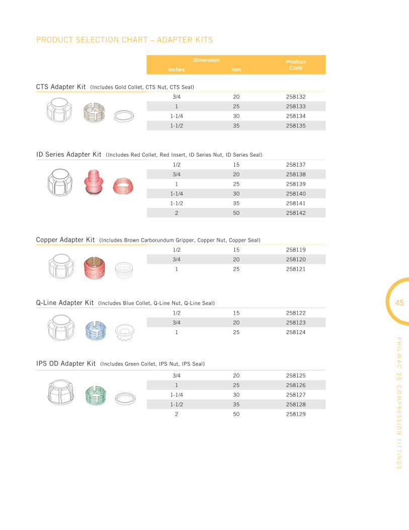
PH
ILM
AC
3G
CO
MP
RE
SS
ION
FIT
TIN
GS
45
PRODUCT SELECTION CHART – ADAPTER KITS
CTS Adapter Kit (Includes Gold Collet, CTS Nut, CTS Seal)
Q-Line Adapter Kit (Includes Blue Collet, Q-Line Nut, Q-Line Seal)
IPS OD Adapter Kit (Includes Green Collet, IPS Nut, IPS Seal)
ID Series Adapter Kit (Includes Red Collet, Red Insert, ID Series Nut, ID Series Seal)
Copper Adapter Kit (Includes Brown Carborundum Gripper, Copper Nut, Copper Seal)
3/4 20 258132
1 25 258133
1-1/4 30 258134
1-1/2 35 258135
1/2 15 258137
3/4 20 258138
1 25 258139
1-1/4 30 258140
1-1/2 35 258141
2 50 258142
1/2 15 258119
3/4 20 258120
1 25 258121
1/2 15 258122
3/4 20 258123
1 25 258124
3/4 20 258125
1 25 258126
1-1/4 30 258127
1-1/2 35 258128
2 50 258129
Dimension ProductCodeinches mm

Dimension ProductCodemm
PH
ILM
AC
3G
CO
MP
RE
SS
ION
FIT
TIN
GS
15 - 21 x 15 - 21 255208
21 - 27 x 21 - 27 255209
27 - 34 x 27 - 34 255210
34 - 39 x 34 - 39 255946
39 - 43 x 39 - 43 255211
47 - 49 x 47 - 49 255947
59 - 61 x 59 - 61 255948
21 - 27 x 15 - 21 255212
27 - 34 x 15 - 21 255214
27 - 34 x 21 - 27 255213
34 - 39 x 27 - 34 255197
39 - 43 x 27 - 34 255215
15 - 21 x 15 - 21 255156
21 - 27 x 21 - 27 255157
15 - 21 x 15 - 21 x 15 - 21 255158
15 - 21 x 3/4 FIPT 255159
21 - 27 x 3/4 FIPT 255167
15 - 21 x 3/4 MIPT 255169
21 - 27 x 3/4 MIPT 255344
27 - 34 x 3/4 MIPT 255345
27 - 34 x 1 MIPT 255196
PRODUCT SELECTION CHART – UNIVERSAL TRANSITION COUPLINGS (UTC) & FITTINGS
Coupling UTC x UTC
Reducing Coupling UTC x UTC
Tee UTC x UTC x FIPT
Elbow UTC x UTC
Tee UTC x UTC x UTC
Adapter UTC x MIPT
46

PRESSURE PIPE & FITTINGS
Blue Brute Piping Systems 6
Blue Brute Fitting Systems 10
Bionax PVCO Pressure Piping Systems 14
IPEX Centurion Piping Systems 16
IPEX Fusible 24
TerraBrute CR 26
CycleTough Piping Systems 30
With a long-proven track record for reliable, watertight performance
underground, IPEX offers the widest range of industrial and domestic,
sanitary and storm water sewage conveyance systems available on the
market today. Third-party certifi ed to applicable industry standards,
all of our state-of-the-art PVC gravity sewer systems are engineered and
manufactured to virtually eliminate the leakage and infi ltration common
with traditional materials like concrete.
Ring-Tite / Enviro-Tite 48
Ultra-Rib 58
Ultra-X2 66
NovaForm PVC Liner 70
Solvent Weld Sewer Fittings 72
SEWER PIPINGSYSTEMS

GASKETED SEWERPIPING SYSTEMS
Ring-Tite 4” - 60” (100mm - 1500mm)
Enviro-Tite 4” - 15” (100mm - 375mm)
RIN
G-
TIT
E
/
EN
VIR
O-
TIT
E
• Gravity Flow Sanitary Sewers
• Storm Sewers • Sewer Laterals
• Industrial Effl uent Lines
APPLICATIONS
STANDARDS
Ring-Tite and Enviro-Tite piping systems are DR35 and DR28 sewer pipes manufactured to demanding ASTM and CSA standards. The two products are identical except for Enviro-Tite having a minimum recycled material content of 50%. Both products have tight joints that can withstand well in excess of both the ASTM and CSA requirements.
1
2
3
4
ADVANTAGES
Corrosion-proof PerformanceIPEX Ring-Tite and Enviro-Tite systems are immune to corrosion from aggressive soils and galvanic action. In addition, H²S and other aggressive chemicals common in sanitary sewage have no effect.
Tight Joints & Lower Treatment CostsEliminate infi ltration and exfi ltration. Ring-Tite and Enviro-Tite joints easily outperform concrete and corrugated PE joints.
Third-Party Certifi cationIPEX Ring-Tite & Enviro-Tite systems are certifi ed to CSA B182.2. Third-party certifi cation is your verifi cation that the product will perform as stated.
High Flow CapacityIPEX’s PVC pipe and fi ttings are manufactured with smooth inner walls and provide systems with a Manning coeffi cient of 0.009, allowing for use of smaller diameters of pipe when compared to rough walled pipe.
RING-TITE
ENVIRO-TITE
B182.2 3624-130/135 D3034 & F679
B182.2 3624-130/135 F1760
VirginPVC
High-Quality,Re-Processed PVC
50%
48
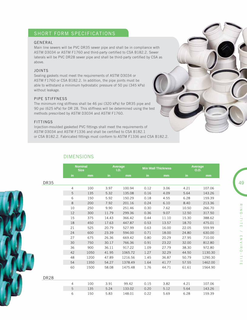
49
RIN
G-
TIT
E
/
EN
VIR
O-
TIT
E
SHORT FORM SPECIFICATIONS
GENERALMain line sewers will be PVC DR35 sewer pipe and shall be in compliance with ASTM D3034 or ASTM F1760 and third-party certifi ed to CSA B182.2. Sewer laterals will be PVC DR28 sewer pipe and shall be third-party certifi ed by CSA as above.
JOINTSSealing gaskets must meet the requirements of ASTM D3034 orASTM F1760 or CSA B182.2. In addition, the pipe joints must be able to withstand a minimum hydrostatic pressure of 50 psi (345 kPa) without leakage.
PIPE STIFFNESSThe minimum ring stiffness shall be 46 psi (320 kPa) for DR35 pipe and 90 psi (625 kPa) for DR 28. This stiffness will be determined using the test methods prescribed by ASTM D3034 and ASTM F1760.
FITTINGSInjection-moulded gasketed PVC fi ttings shall meet the requirements ofASTM D3034 and ASTM F1336 and shall be certifi ed to CSA B182.1 or CSA B182.2. Fabricated fi ttings must conform to ASTM F1336 and CSA B182.2.
DIMENSIONS
NominalSize
AverageI.D. Min Wall Thickness Average
O.D.
in mm in mm in mm in mm
4 100 3.97 100.94 0.12 3.06 4.21 107.06
5 135 5.32 135.08 0.16 4.09 5.64 143.26
6 150 5.92 150.29 0.18 4.55 6.28 159.39
8 200 7.92 201.16 0.24 6.10 8.40 213.36
10 250 9.90 251.46 0.30 7.62 10.50 266.70
12 300 11.79 299.36 0.36 9.07 12.50 317.50
15 375 14.43 366.42 0.44 11.10 15.30 388.62
18 450 17.63 447.87 0.53 13.57 18.70 475.01
21 525 20.79 527.99 0.63 16.00 22.05 559.99
24 600 23.39 594.00 0.71 18.00 24.80 630.00
27 675 26.36 669.42 0.80 20.29 27.95 710.00
30 750 30.17 766.36 0.91 23.22 32.00 812.80
36 900 36.11 917.22 1.09 27.79 38.30 972.80
42 1050 41.95 1065.72 1.27 32.29 44.50 1130.30
48 1200 47.89 1216.56 1.45 36.87 50.79 1290.30
54 1350 54.27 1378.49 1.64 41.77 57.55 1462.00
60 1500 58.08 1475.48 1.76 44.71 61.61 1564.90
4 100 3.91 99.42 0.15 3.82 4.21 107.06
5 135 5.24 133.02 0.20 5.12 5.64 143.26
6 150 5.83 148.01 0.22 5.69 6.28 159.39
DR35
DR28
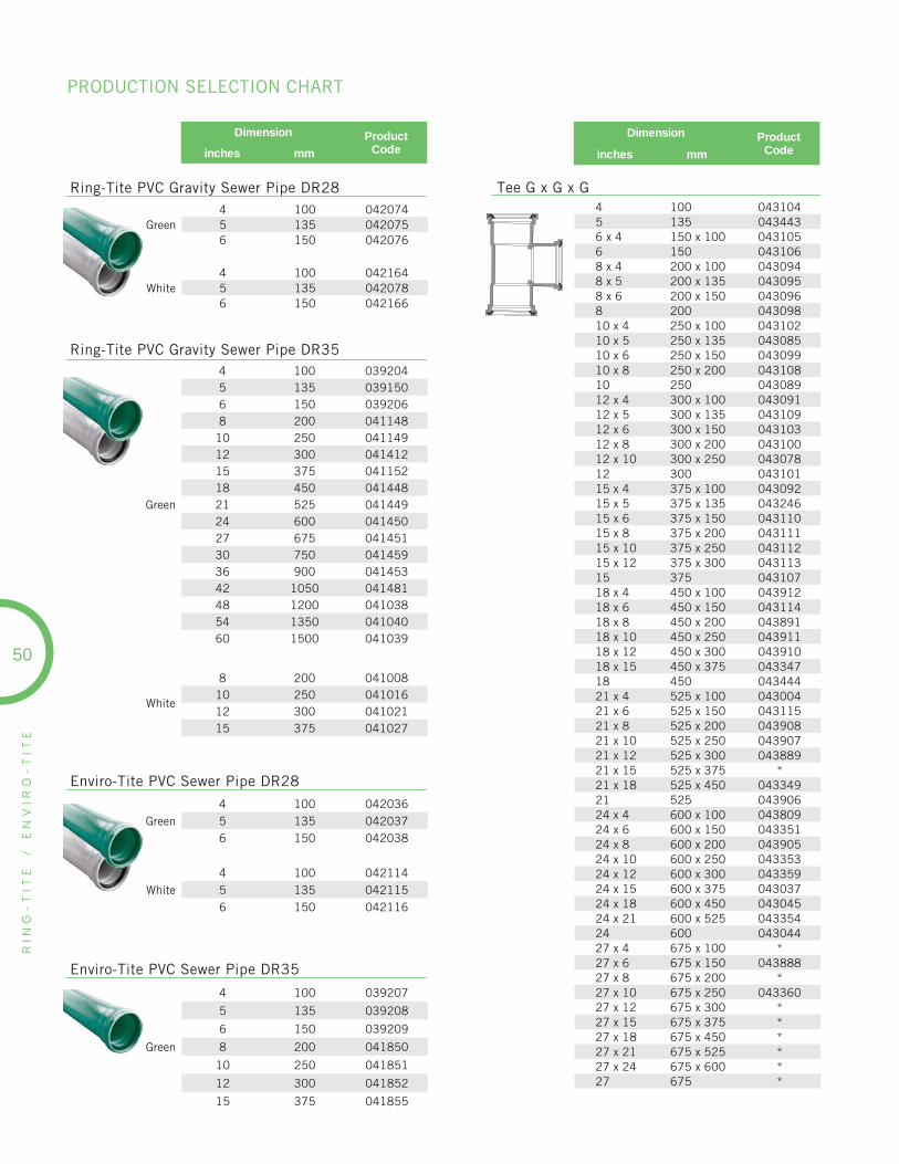
RIN
G-
TIT
E
/
EN
VIR
O-
TIT
E
4 100 0431045 135 0434436 x 4 150 x 100 0431056 150 0431068 x 4 200 x 100 0430948 x 5 200 x 135 0430958 x 6 200 x 150 0430968 200 04309810 x 4 250 x 100 04310210 x 5 250 x 135 04308510 x 6 250 x 150 04309910 x 8 250 x 200 04310810 250 04308912 x 4 300 x 100 04309112 x 5 300 x 135 04310912 x 6 300 x 150 04310312 x 8 300 x 200 04310012 x 10 300 x 250 04307812 300 04310115 x 4 375 x 100 04309215 x 5 375 x 135 04324615 x 6 375 x 150 04311015 x 8 375 x 200 04311115 x 10 375 x 250 04311215 x 12 375 x 300 04311315 375 04310718 x 4 450 x 100 04391218 x 6 450 x 150 04311418 x 8 450 x 200 04389118 x 10 450 x 250 04391118 x 12 450 x 300 04391018 x 15 450 x 375 04334718 450 04344421 x 4 525 x 100 04300421 x 6 525 x 150 04311521 x 8 525 x 200 04390821 x 10 525 x 250 04390721 x 12 525 x 300 04388921 x 15 525 x 375 *21 x 18 525 x 450 04334921 525 04390624 x 4 600 x 100 04380924 x 6 600 x 150 04335124 x 8 600 x 200 04390524 x 10 600 x 250 04335324 x 12 600 x 300 04335924 x 15 600 x 375 04303724 x 18 600 x 450 04304524 x 21 600 x 525 04335424 600 04304427 x 4 675 x 100 *27 x 6 675 x 150 04388827 x 8 675 x 200 *27 x 10 675 x 250 04336027 x 12 675 x 300 *27 x 15 675 x 375 *27 x 18 675 x 450 *27 x 21 675 x 525 *27 x 24 675 x 600 *27 675 *
Dimension ProductCodeinches mm
Green4 100 0420745 135 0420756 150 042076
White4 100 0421645 135 0420786 150 042166
Ring-Tite PVC Gravity Sewer Pipe DR28
Ring-Tite PVC Gravity Sewer Pipe DR35
Green
4 100 0392045 135 0391506 150 0392068 200 041148
10 250 04114912 300 04141215 375 04115218 450 04144821 525 04144924 600 04145027 675 04145130 750 04145936 900 04145342 1050 04148148 1200 04103854 1350 04104060 1500 041039
White
8 200 04100810 250 04101612 300 04102115 375 041027
Enviro-Tite PVC Sewer Pipe DR28
Green4 100 0420365 135 0420376 150 042038
White4 100 0421145 135 0421156 150 042116
Enviro-Tite PVC Sewer Pipe DR35
Green
4 100 039207
5 135 039208
6 150 039209
8 200 041850
10 250 041851
12 300 041852
15 375 041855
Dimension ProductCodeinches mm
Tee G x G x G
50
PRODUCTION SELECTION CHART
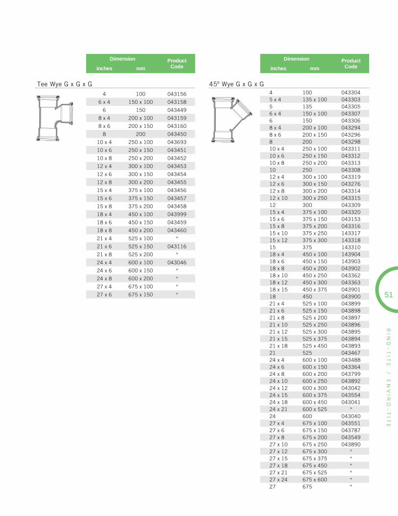
RIN
G-
TIT
E
/
EN
VIR
O-
TIT
E
51
Dimension ProductCodeinches mm
4 100 043156
6 x 4 150 x 100 043158
6 150 043449
8 x 4 200 x 100 043159
8 x 6 200 x 150 043160
8 200 043450
10 x 4 250 x 100 043693
10 x 6 250 x 150 043451
10 x 8 250 x 200 043452
12 x 4 300 x 100 043453
12 x 6 300 x 150 043454
12 x 8 300 x 200 043455
15 x 4 375 x 100 043456
15 x 6 375 x 150 043457
15 x 8 375 x 200 043458
18 x 4 450 x 100 043999
18 x 6 450 x 150 043459
18 x 8 450 x 200 043460
21 x 4 525 x 100 *
21 x 6 525 x 150 043116
21 x 8 525 x 200 *
24 x 4 600 x 100 043046
24 x 6 600 x 150 *
24 x 8 600 x 200 *
27 x 4 675 x 100 *
27 x 6 675 x 150 *
Tee Wye G x G x G4 100 0433045 x 4 135 x 100 0433035 135 0433056 x 4 150 x 100 0433076 150 0433068 x 4 200 x 100 0432948 x 6 200 x 150 0432968 200 04329810 x 4 250 x 100 04331110 x 6 250 x 150 04331210 x 8 250 x 200 04331310 250 043308
45º Wye G x G x G
Dimension ProductCodeinches mm
12 x 4 300 x 100 04331912 x 6 300 x 150 04327612 x 8 300 x 200 04331412 x 10 300 x 250 04331512 300 04330915 x 4 375 x 100 04332015 x 6 375 x 150 04315315 x 8 375 x 200 04331615 x 10 375 x 250 14331715 x 12 375 x 300 14331815 375 14331018 x 4 450 x 100 14390418 x 6 450 x 150 14390318 x 8 450 x 200 04390218 x 10 450 x 250 04336218 x 12 450 x 300 04336318 x 15 450 x 375 04390118 450 04390021 x 4 525 x 100 04389921 x 6 525 x 150 04389821 x 8 525 x 200 04389721 x 10 525 x 250 04389621 x 12 525 x 300 04389521 x 15 525 x 375 04389421 x 18 525 x 450 04389321 525 04346724 x 4 600 x 100 04348824 x 6 600 x 150 04336424 x 8 600 x 200 04379924 x 10 600 x 250 04389224 x 12 600 x 300 04304224 x 15 600 x 375 04355424 x 18 600 x 450 04304124 x 21 600 x 525 *24 600 04304027 x 4 675 x 100 04355127 x 6 675 x 150 04378727 x 8 675 x 200 04354927 x 10 675 x 250 04389027 x 12 675 x 300 *27 x 15 675 x 375 *27 x 18 675 x 450 *27 x 21 675 x 525 *27 x 24 675 x 600 *27 675 *
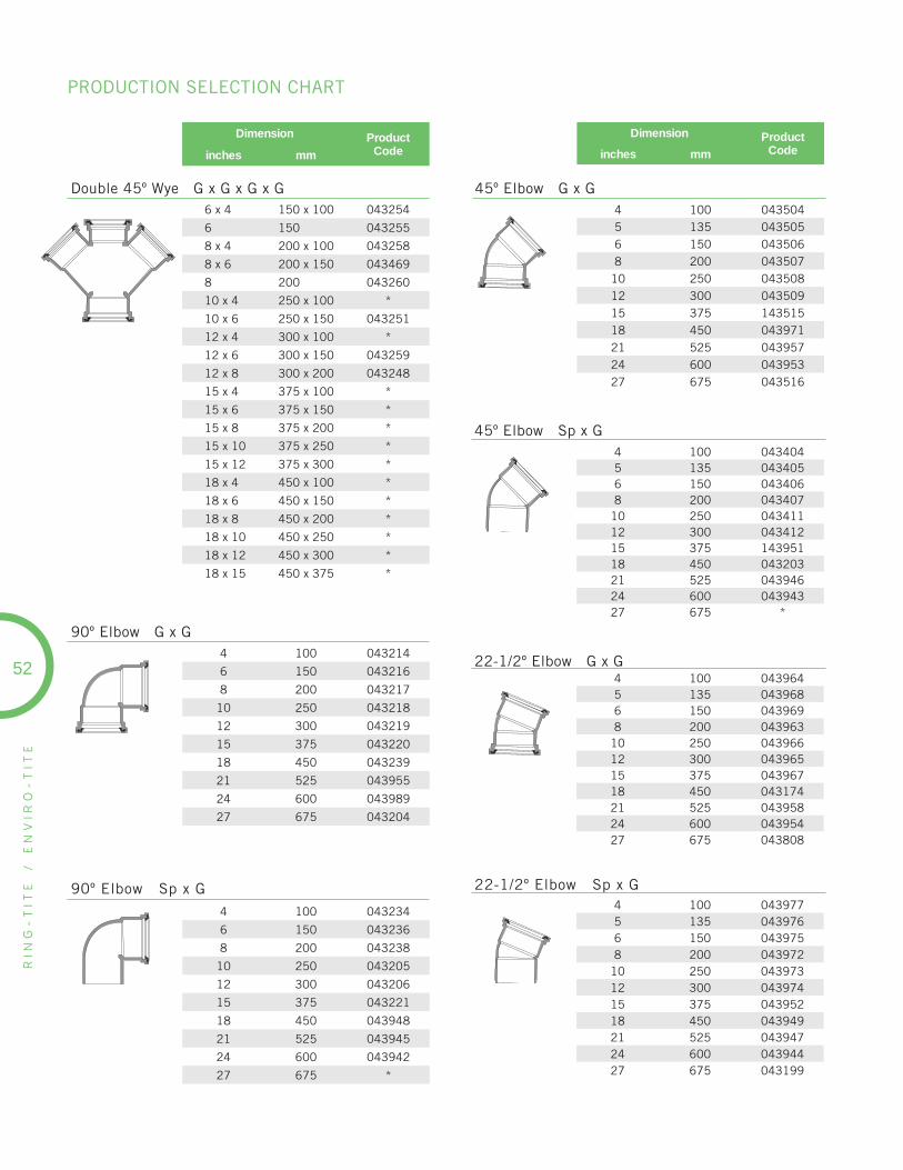
RIN
G-
TIT
E
/
EN
VIR
O-
TIT
E
Dimension ProductCodeinches mm
6 x 4 150 x 100 043254
6 150 043255
8 x 4 200 x 100 043258
8 x 6 200 x 150 043469
8 200 043260
10 x 4 250 x 100 *
10 x 6 250 x 150 043251
12 x 4 300 x 100 *
12 x 6 300 x 150 043259
12 x 8 300 x 200 043248
15 x 4 375 x 100 *
15 x 6 375 x 150 *
15 x 8 375 x 200 *
15 x 10 375 x 250 *
15 x 12 375 x 300 *
18 x 4 450 x 100 *
18 x 6 450 x 150 *
18 x 8 450 x 200 *
18 x 10 450 x 250 *
18 x 12 450 x 300 *
18 x 15 450 x 375 *
Double 45º Wye G x G x G x G
90º Elbow Sp x G
4 100 043234
6 150 043236
8 200 043238
10 250 043205
12 300 043206
15 375 043221
18 450 043948
21 525 043945
24 600 043942
27 675 *
90º Elbow G x G4 100 043214
6 150 043216
8 200 043217
10 250 043218
12 300 043219
15 375 043220
18 450 043239
21 525 043955
24 600 043989
27 675 043204
45º Elbow Sp x G4 100 0434045 135 0434056 150 0434068 200 043407
10 250 04341112 300 04341215 375 14395118 450 04320321 525 04394624 600 04394327 675 *
4 100 0435045 135 0435056 150 0435068 200 043507
10 250 04350812 300 04350915 375 14351518 450 04397121 525 04395724 600 04395327 675 043516
Dimension ProductCodeinches mm
45º Elbow G x G
4 100 0439645 135 0439686 150 0439698 200 043963
10 250 04396612 300 04396515 375 04396718 450 04317421 525 04395824 600 04395427 675 043808
22-1/2º Elbow G x G
4 100 0439775 135 0439766 150 0439758 200 043972
10 250 04397312 300 04397415 375 04395218 450 04394921 525 04394724 600 04394427 675 043199
22-1/2º Elbow Sp x G
52
PRODUCTION SELECTION CHART

RIN
G-
TIT
E
/
EN
VIR
O-
TIT
E
53
Dimension ProductCodeinches mm
Dimension ProductCodeinches mm
4 100 043172
5 135 043366
6 150 043922
8 200 043139
10 250 043140
12 300 043141
22-1/2º Long Radius Bend Sp x G
4 100 043143
5 135 043365
6 150 043166
8 200 043144
10 250 043151
12 300 043152
45º Long Radius Bend Sp x G
Saddle Tee (c/w 2 straps)
6 x 4 150 x 100 043125
8 x 4 200 x 100 043124
8 x 6 200 x 150 043126
10 x 4 250 x 100 043127
10 x 6 250 x 150 043129
12 x 4 300 x 100 043130
12 x 6 300 x 150 043132
15 x 4 375 x 100 043133
15 x 6 375 x 150 043135
18 x 4 450 x 100 043429
18 x 6 450 x 150 043431
21 x 4 525 x 100 043432
21 x 6 525 x 150 043433
24 x 4 600 x 100 043434
24 x 6 600 x 150 043585
27 x 4 675 x 100 043703
27 x 6 675 x 150 043477
6 x 4 150 x 100 043594
8 x 4 200 x 100 043595
8 x 6 200 x 150 043598
10 x 4 250 x 100 043599
10 x 6 250 x 150 043596
12 x 4 300 x 100 043600
12 x 6 300 x 150 043597
15 x 4 375 x 100 043603
15 x 6 375 x 150 043602
18 x 4 450 x 100 043440
18 x 6 450 x 150 043441
21 x 4 525 x 100 043442
21 x 6 525 x 150 *
24 x 4 600 x 100 *
24 x 6 600 x 150 043584
27 x 4 675 x 100 *
27 x 6 675 x 150 *
Saddle Wye (c/w 2 straps)
4 100 043624
5 135 043625
6 150 043626
8 200 043627
10 250 043630
12 300 143631
15 375 043637
18 450 043941
21 525 043938
24 600 043937
27 675 043670
Repair Coupling G x G (w/o pipe stop)
4 100 043640
5 135 043641
6 150 043643
8 200 043644
10 250 043645
12 300 043632
15 375 043638
18 450 043935
21 525 043934
24 600 043933
27 675 043940
Coupling G x G (with stop)
Spigot Plug
4 100 0437345 135 0437356 150 0437368 200 043738
10 250 04374012 300 04374115 375 04374218 450 04374321 525 04374424 600 04374527 675 043751

RIN
G-
TIT
E
/
EN
VIR
O-
TIT
E
Increaser SP x G
Dimension ProductCodeinches mm
5 x 4 135 x 100 043729
6 x 4 150 x 100 043939
8 x 4 200 x 100 043621
8 x 6 200 x 150 043620
10 x 4 250 x 100 043368
10 x 6 250 x 150 043618
10 x 8 250 x 200 043622
12 x 6 300 x 150 043617
12 x 8 300 x 200 043616
12 x 10 300 x 250 043623
15 x 4 375 x 100 043369
15 x 6 375 x 150 043300
15 x 8 375 x 200 043370
15 x 10 375 x 250 043371
15 x 12 375 x 300 043615
18 x 8 450 x 200 043538
18 x 10 450 x 250 043678
18 x 12 450 x 300 043629
18 x 15 450 x 375 043539
21 x 12 525 x 300 *
21 x 15 525 x 375 043288
21 x 18 525 x 450 043673
24 x 12 600 x 300 043047
24 x 15 600 x 375 043048
24 x 18 600 x 450 043674
24 x 21 600 x 525 043675
27 x 12 675 x 300 043679
27 x 15 675 x 375 *
27 x 18 675 x 450 043289
27 x 21 675 x 525 043676
27 x 24 675 x 600 043677
Dimension ProductCodeinches mm
Increaser Coupling G x G
Eccentric Increaser Sp x G
6 x 4 150 x 100 043237
10 x 4 250 x 100 043268
10 x 5 250 x 135 043655
10 x 6 250 x 150 043269
10 x 8 250 x 200 043270
12 x 4 300 x 100 043271
12 x 5 300 x 135 043656
12 x 6 300 x 150 043272
12 x 8 300 x 200 043273
12 x 10 300 x 250 043274
15 x 4 375 x 100 043275
15 x 6 375 x 150 043277
15 x 8 375 x 200 043278
15 x 10 375 x 250 043279
15 x 12 375 x 300 043280
18 x 4 450 x 100 043281
18 x 6 450 x 150 043282
18 x 8 450 x 200 043230
18 x 10 450 x 250 043512
18 x 12 450 x 300 043283
18 x 15 450 x 375 043284
21 x 15 525 x 375 043285
21 x 18 525 x 450 *
24 x 18 600 x 450 *
24 x 21 600 x 525 *
27 x 21 675 x 525 *
27 x 24 675 x 600 *
6 x 4 150 x 100 0438828 x 4 200 x 100 0435368 x 6 200 x 150 04353510 x 6 250 x 150 04352810 x 8 250 x 200 04353112 x 6 300 x 150 14353012 x 8 300 x 200 14353212 x 10 300 x 250 14352015 x 6 375 x 150 04393115 x 8 375 x 200 04393015 x 10 375 x 250 04353315 x 12 375 x 300 04353418 x 8 450 x 200 04369018 x 10 450 x 250 04392918 x 12 450 x 300 04329318 x 15 450 x 375 04392821 x 4 525 x 100 04392721 x 8 525 x 200 04392621 x 10 525 x 250 04392521 x 12 525 x 300 04392421 x 15 525 x 375 04392321 x 18 525 x 450 04392124 x 4 600 x 100 04392024 x 6 600 x 150 04391924 x 8 600 x 200 04391824 x 10 600 x 250 04391724 x 12 600 x 300 04391624 x 15 600 x 375 04391524 x 18 600 x 450 04391424 x 21 600 x 525 04391327 x 12 675 x 300 *27 x 15 675 x 375 *27 x 18 675 x 450 *27 x 21 675 x 525 *27 x 24 675 x 600 *
54
PRODUCTION SELECTION CHART

RIN
G-
TIT
E
/
EN
VIR
O-
TIT
E
55
Dimension ProductCodeinches mm
Dimension ProductCodeinches mm
4 100 043959
5 135 043960
6 150 043988
8 200 043961
10 250 043886
12 300 043987
15 375 043962
18 450 043746
21 525 043747
24 600 043168
27 675 043749
Cap
6 150 043760
Bell Cleanout Adapter
6 150 043750
Spigot Cleanout Adapter
4 100 043712
5 x 4 135 x 100 043711
6 x 4 150 x 100 043713
Adapter Coupling G x G (PVC Sp to ABS)
4 100 043720
5 x 4 135 x 100 043642
Adapter Coupling G x G (PVC Sp to AC Sp)
4 100 043169
6 150 043170
8 200 043171
Clay Tile Adapter Sp x Sp (Clay G to PVC G)
6 150 081319
M Adapter Sp x G
4 x 4 100 x 100 043724
8 x 8 200 x 200 043727
Bushing Adapter AC Bell x PVC Sp (Sp x G)
4 100 043858
Adapter PVC Gasket x PVC Hub (G x Solvent Weld Hub)
4 100 043770
6 150 043771
8 200 043772
Adapter PVC Bell (off concrete main)
6 x 5 150 x 135 043619
Bushing Adapter PVC Bell x AC Sp (Sp x G)
4 100 043050
5 135 043056
6 150 043051
8 200 043052
10 250 043053
12 300 043054
15 375 043055
18 450 043295
21 525 *
24 600 043058
Manhole Gasket Adapter
Sanded Manhole Bell (w/o stop)
4 100 043060
5 135 043334
6 150 043061
8 200 043063
10 250 043064
12 300 043065
15 375 043062
18 450 043066
21 525 043067
24 600 043068
27 675 043591

RIN
G-
TIT
E
/
EN
VIR
O-
TIT
E
Dimension ProductCodeinches mm
Dimension ProductCodeinches mm
Description ProductCodeMetric
Manhole Adapter G x SP (24”/600mm long)
4 100 043297
5 135 043299
6 150 043301
8 200 043302
10 250 043328
12 300 043329
15 375 043330
18 450 043331
21 525 043548
24 600 043332
27 675 *
Wing Adapter (mortar-on)
4 100 043190
5 135 043192
6 150 043191
8 200 043193
10 250 043194
12 300 043195
15 375 043196
18 450 *
21 525 *
24 600 *
27 675 *
Universal Storm Sewer Saddle (c/w Bell & Seating Gasket)
4 100 082244
5 135 082245
6 150 082246
8 200 082248
Hand Tight Expansion End Plug
4 100 043200
5 135 043201
6 150 043202
8 200 043212
Stainless Steel Strap6 150 043346
8 200 043348
10 250 043350
12 300 043352
56
Boot Jack - Sanitary
5x4x4x4 (P) 125x100x100x100 (P) 043705
6x5x5x4 (P) 150x125x125x100 (P) 043706
6x4x4x4 (P) 150x100x100x100 (P) 043707
Boot Jack - Storm
5x4x4x4 (P) 125x100x100x100 (P) 043715
6x5x5x4 (P) 150x125x125x100 (P) 043716
6x4x4x4 (P) 150x100x100x100 (P) 043717
Test Tee - Sanitary
4x4x4 (C) 100x100x100 (C) 043646
5x4x4 (C) 125x100x100 (C) 043647
5x5x4 (C) 125x125x100 (C) 043648
6x6x4 (C) 150x150x100 (C) 043649
Test Tee - Storm
4x4x4 (C) 100x100x100 (C) 043666
5x4x4 (C) 125x100x100 (C) 043667
5x5x4 (C) 125x125x100 (C) 043668
6x6x4 (C) 150x150x100 (C) 043669
PRODUCTION SELECTION CHART
Lubricant
1 kg container 074811
4 kg container 074812
(P): Plug (C): Cap

RIN
G-
TIT
E
/
EN
VIR
O-
TIT
E
57
Dimension ProductCodeinches mm
8 x 4 200 x 100 072434
10 x 4 250 x 100 072440
10 x 6 250 x 150 072441
12 x 4 300 x 100 072436
12 x 6 300 x 150 072437
12 x 8 300 x 200 072442
15 x 4 375 x 100 072438
15 x 6 375 x 150 072443
15 x 8 375 x 200 072444
18 x 4 450 x 100 072439
18 x 6 450 x 150 072445
18 x 8 450 x 200 072446
18 x 10 450 x 250 072447
18 x 12 450 x 300 072448
21 x 4 525 x 100 072449
21 x 6 525 x 150 072450
21 x 8 525 x 200 072451
21 x 10 525 x 250 072452
21 x 12 525 x 300 072453
21 x 15 525 x 375 -
24 x 4 600 x 100 072583
24 x 6 600 x 150 072584
24 x 8 600 x 200 072585
24 x 10 600 x 250 072586
24 x 12 600 x 300 072587
27 x 4 675 x 100 072588
27 x 6 675 x 150 072589
27 x 8 675 x 200 072590
27 x 10 675 x 250 072591
27 x 12 675 x 300 072592
* 30 x 4 750 x 100 072593
* 30 x 6 750 x 150 072594
* 30 x 8 750 x 200 072595
* 30 x 10 750 x 250 072596
* 30 x 12 750 x 300 072597
** 36 x 4 900 x 100 072598
** 36 x 6 900 x 150 072599
** 36 x 8 900 x 200 072600
** 36 x 10 900 x 250 072601
** 36 x 12 900 x 300 072602
* 30” DR35 32.000” O.D. Pipe w .915 WT Pipe** 36” DR35 38.300” O.D. Pipe w 1.100 WT Pipe
InsertaTees (for DR35 PVC Sewer Pipe)
IPEX OFFERS A 4” x 3” SDR 35 ADAPTER BUSHING
IPEX offers a new adapter bushing to create a transition between a SDR35 Drain Line solvent weld system and a Ring-Tite® gasket system.
Defl ection stress on buried piping systems is a common occurrence in construction and can inadvertently place unwanted stress on joints. The new adapter bushing is designed with a 4” long spigot to reduce any chance of the joint pulling apart as a result of defl eciton stress.
Dimension ProductCodeinches
SDR35 Adapter Bushing(for transition between Solvent Weld & Ring-Tite
4 x 3 Extended Sp x H 243040
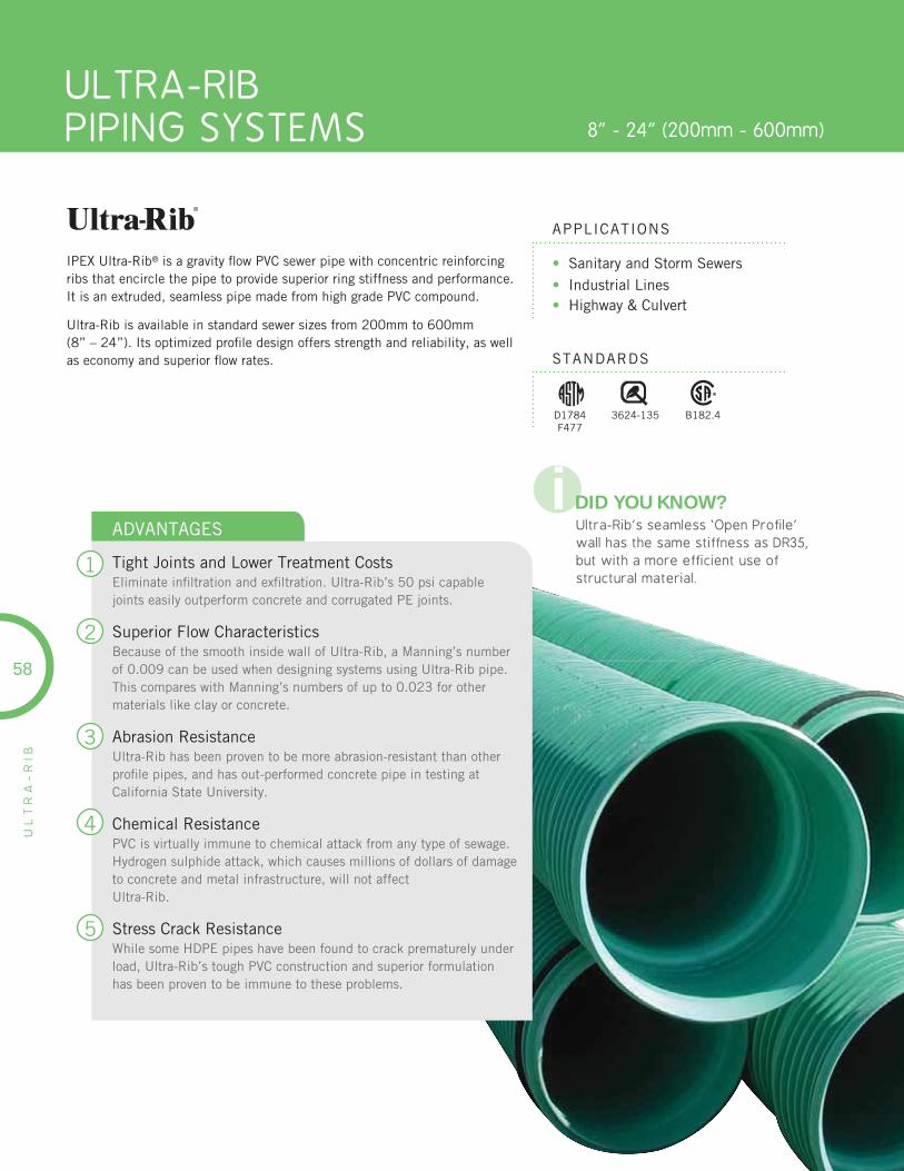
ULTRA-RIBPIPING SYSTEMS 8” - 24” (200mm - 600mm)
UL
TR
A-
RIB
• Sanitary and Storm Sewers• Industrial Lines • Highway & Culvert
APPLICATIONS
STANDARDS
IPEX Ultra-Rib® is a gravity fl ow PVC sewer pipe with concentric reinforcing ribs that encircle the pipe to provide superior ring stiffness and performance. It is an extruded, seamless pipe made from high grade PVC compound.
Ultra-Rib is available in standard sewer sizes from 200mm to 600mm(8” – 24”). Its optimized profi le design offers strength and reliability, as well as economy and superior fl ow rates.
1
2
3
4
5
ADVANTAGES
Tight Joints and Lower Treatment CostsEliminate infi ltration and exfi ltration. Ultra-Rib’s 50 psi capable joints easily outperform concrete and corrugated PE joints.
Superior Flow CharacteristicsBecause of the smooth inside wall of Ultra-Rib, a Manning’s number of 0.009 can be used when designing systems using Ultra-Rib pipe. This compares with Manning’s numbers of up to 0.023 for other materials like clay or concrete.
Abrasion ResistanceUltra-Rib has been proven to be more abrasion-resistant than other profi le pipes, and has out-performed concrete pipe in testing at California State University.
Chemical ResistancePVC is virtually immune to chemical attack from any type of sewage. Hydrogen sulphide attack, which causes millions of dollars of damage to concrete and metal infrastructure, will not affectUltra-Rib.
Stress Crack ResistanceWhile some HDPE pipes have been found to crack prematurely under load, Ultra-Rib’s tough PVC construction and superior formulation has been proven to be immune to these problems.
58
3624-135D1784F477
B182.4
i DID YOU KNOW?Ultra-Rib’s seamless ‘Open Profile’ wall has the same stiffness as DR35, but with a more efficient use of structural material.
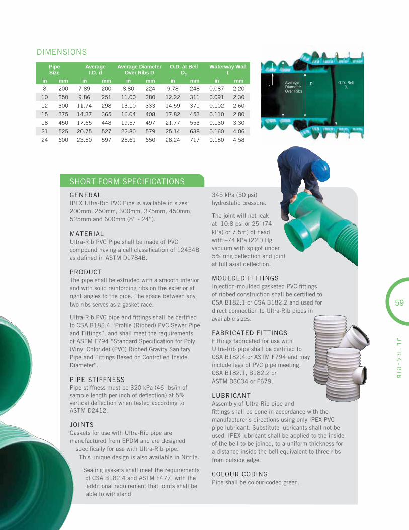
59
UL
TR
A-
RIB
PipeSize
AverageI.D. d
Average DiameterOver Ribs D
O.D. at Bell D3
Waterway Wallt
in mm in mm in mm in mm in mm
8 200 7.89 200 8.80 224 9.78 248 0.087 2.20
10 250 9.86 251 11.00 280 12.22 311 0.091 2.30
12 300 11.74 298 13.10 333 14.59 371 0.102 2.60
15 375 14.37 365 16.04 408 17.82 453 0.110 2.80
18 450 17.65 448 19.57 497 21.77 553 0.130 3.30
21 525 20.75 527 22.80 579 25.14 638 0.160 4.06
24 600 23.50 597 25.61 650 28.24 717 0.180 4.58
t AverageDiameterOver Ribs
I.D. O.D. BellD3
DIMENSIONS
GENERALIPEX Ultra-Rib PVC Pipe is available in sizes 200mm, 250mm, 300mm, 375mm, 450mm, 525mm and 600mm (8” - 24”).
MATERIALUltra-Rib PVC Pipe shall be made of PVC compound having a cell classifi cation of 12454Bas defi ned in ASTM D1784B.
PRODUCTThe pipe shall be extruded with a smooth interior and with solid reinforcing ribs on the exterior at right angles to the pipe. The space between any two ribs serves as a gasket race.
Ultra-Rib PVC pipe and fi ttings shall be certifi ed to CSA B182.4 “Profi le (Ribbed) PVC Sewer Pipe and Fittings”, and shall meet the requirements of ASTM F794 “Standard Specifi cation for Poly (Vinyl Chloride) (PVC) Ribbed Gravity Sanitary Pipe and Fittings Based on Controlled Inside Diameter”.
PIPE STIFFNESSPipe stiffness must be 320 kPa (46 lbs/in of sample length per inch of defl ection) at 5%vertical defl ection when tested according toASTM D2412.
JOINTSGaskets for use with Ultra-Rib pipe are manufactured from EPDM and are designed
specifi cally for use with Ultra-Rib pipe.This unique design is also available in Nitrile.
Sealing gaskets shall meet the requirements of CSA B182.4 and ASTM F477, with the additional requirement that joints shall be able to withstand
345 kPa (50 psi) hydrostatic pressure.
The joint will not leak at 10.8 psi or 25’ (74 kPa) or 7.5m) of head with –74 kPa (22”) Hg vacuum with spigot under 5% ring defl ection and joint at full axial defl ection.
MOULDED FITTINGSInjection-moulded gasketed PVC fi ttings of ribbed construction shall be certifi ed toCSA B182.1 or CSA B182.2 and used fordirect connection to Ultra-Rib pipes in available sizes.
FABRICATED FITTINGSFittings fabricated for use withUltra-Rib pipe shall be certifi ed toCSA B182.4 or ASTM F794 and may include legs of PVC pipe meetingCSA B182.1, B182.2 orASTM D3034 or F679.
LUBRICANTAssembly of Ultra-Rib pipe and fi ttings shall be done in accordance with the manufacturer’s directions using only IPEX PVC pipe lubricant. Substitute lubricants shall not be used. IPEX lubricant shall be applied to the inside of the bell to be joined, to a uniform thickness for a distance inside the bell equivalent to three ribs from outside edge.
COLOUR CODINGPipe shall be colour-coded green.
SHORT FORM SPECIFICATIONS
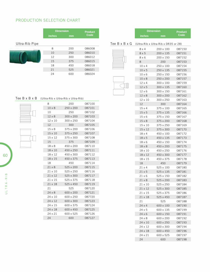
UL
TR
A-
RIB
60
Dimension ProductCodeinches mm
Dimension ProductCodeinches mm
8 200 087100
10 x 8 250 x 200 087101
10 250 087102
12 x 8 300 x 200 087103
12 x 10 300 x 250 087104
12 300 087105
15 x 8 375 x 200 087106
15 x 10 375 x 250 087107
15 x 12 375 x 300 087108
15 375 087109
18 x 8 450 x 200 087110
18 x 10 450 x 250 087111
18 x 12 450 x 300 087112
18 x 15 450 x 375 087113
18 450 087114
21 x 8 525 x 200 087115
21 x 10 525 x 250 087116
21 x 12 525 x 300 087117
21 x 15 525 x 375 087118
21 x 18 525 x 450 087119
21 525 087120
24 x 8 600 x 200 087121
24 x 10 600 x 250 087720
24 x 12 600 x 300 087123
24 x 15 600 x 375 087124
24 x 18 600 x 450 087125
24 x 21 600 x 525 087126
24 600 087127
8 200 086008
10 250 086010
12 300 086012
15 375 086015
18 450 086018
21 525 086021
24 600 086024
Tee B x B x B (Ultra-Rib x Ultra-Rib x Ultra-Rib)
Tee B x B x G (Ultra-Rib x Ultra-Rib x DR35 or 28)Ultra-Rib Pipe
8 x 4 200 x 100 087150
8 x 5 200 x 135 087151
8 x 6 200 x 150 087152
8 200 087153
10 x 4 250 x 100 087154
10 x 5 250 x 135 087155
10 x 6 250 x 150 087156
10 x 8 250 x 200 087157
12 x 4 300 x 100 087159
12 x 5 300 x 135 087160
12 x 6 300 x 150 087161
12 x 8 300 x 200 087162
12 x 10 300 x 250 087163
12 300 087164
15 x 4 375 x 100 087165
15 x 5 375 x 135 087166
15 x 6 375 x 150 087167
15 x 8 375 x 200 087168
15 x 10 375 x 250 087169
15 x 12 375 x 300 087170
18 x 4 450 x 100 087172
18 x 5 450 x 135 087173
18 x 6 450 x 150 087174
18 x 8 450 x 200 087175
18 x 10 450 x 250 087176
18 x 12 450 x 300 087177
18 x 15 450 x 375 087178
18 450 087179
21 x 4 525 x 100 087180
21 x 5 525 x 135 087181
21 x 6 525 x 150 087182
21 x 8 525 x 200 087183
21 x 10 525 x 250 087184
21 x 12 525 x 300 087185
21 x 15 525 x 375 087186
21 x 18 525 x 450 087187
21 525 087188
24 x 4 600 x 100 087190
24 x 5 600 x 135 087199
24 x 6 600 x 150 087191
24 x 8 600 x 200 087192
24 x 10 600 x 250 087193
24 x 12 600 x 300 087194
24 x 18 600 x 450 087196
24 x 21 600 x 525 087197
24 600 087198
PRODUCTION SELECTION CHART

UL
TR
A-
RIB
61
Dimension ProductCodeinches mm
Dimension ProductCodeinches mm
8 x 4 200 x 100 087250
8 x 5 200 x 135 087251
8 x 6 200 x 150 087252
8 200 087253
10 x 4 250 x 100 087254
10 x 5 250 x 135 087255
10 x 6 250 x 150 087256
10 x 8 250 x 200 087257
10 250 087258
12 x 4 300 x 100 087259
12 x 5 300 x 135 087260
12 x 6 300 x 150 087261
12 x 8 300 x 200 087262
12 x 10 300 x 250 087263
12 300 087264
15 x 4 375 x 100 087265
15 x 5 375 x 135 087266
15 x 6 375 x 150 087267
15 x 8 375 x 200 087268
15 x 10 375 x 250 087269
15 x 12 375 x 300 087270
15 375 087271
18 x 4 450 x 100 087272
18 x 5 450 x 135 087273
18 x 6 450 x 150 087274
18 x 8 450 x 200 087275
18 x 10 450 x 250 087276
18 x 12 450 x 300 087277
18 x 15 450 x 375 087278
18 450 087279
21 x 4 525 x 100 087235
21 x 5 525 x 135 087236
21 x 6 525 x 150 087237
21 x 8 525 x 200 087238
21 x 10 525 x 250 087239
21 x 12 525 x 300 087240
21 x 15 525 x 375 087241
21 x 18 525 x 450 087242
21 525 087243
24 x 4 600 x 100 087360
24 x 5 600 x 135 087359
24 x 6 600 x 150 087361
24 x 8 600 x 200 087362
24 x 10 600 x 250 087363
24 x 12 600 x 300 087364
24 x 15 600 x 375 087365
24 x 18 600 x 450 087366
24 x 21 600 x 525 087367
24 600 087368
Wye B x B x G (Ultra-Rib x Ultra-Rib x DR35 or 28)
8 200 087280
10 x 8 250 x 200 087281
10 250 087282
12 x 8 300 x 200 087283
12 x 10 300 x 250 087284
12 300 087285
15 x 8 375 x 200 087286
15 x 10 375 x 250 087287
15 x 12 375 x 300 087288
15 375 087289
18 x 8 450 x 200 087290
18 x 10 450 x 250 087291
18 x 12 450 x 300 087292
18 x 15 450 x 375 087293
18 450 087294
21 x 8 525 x 200 087295
21 x 10 525 x 250 087296
21 x 12 525 x 300 087297
21 x 15 525 x 375 087298
21 x 18 525 x 450 087299
21 525 087316
24 x 8 600 x 200 087317
24 x 10 600 x 250 087318
24 x 12 600 x 300 087319
24 x 15 600 x 375 087320
24 x 18 600 x 450 087321
24 x 21 600 x 525 087322
24 600 087323
Wye B x B x B (Ultra-Rib x Ultra-Rib x Ultra-Rib)
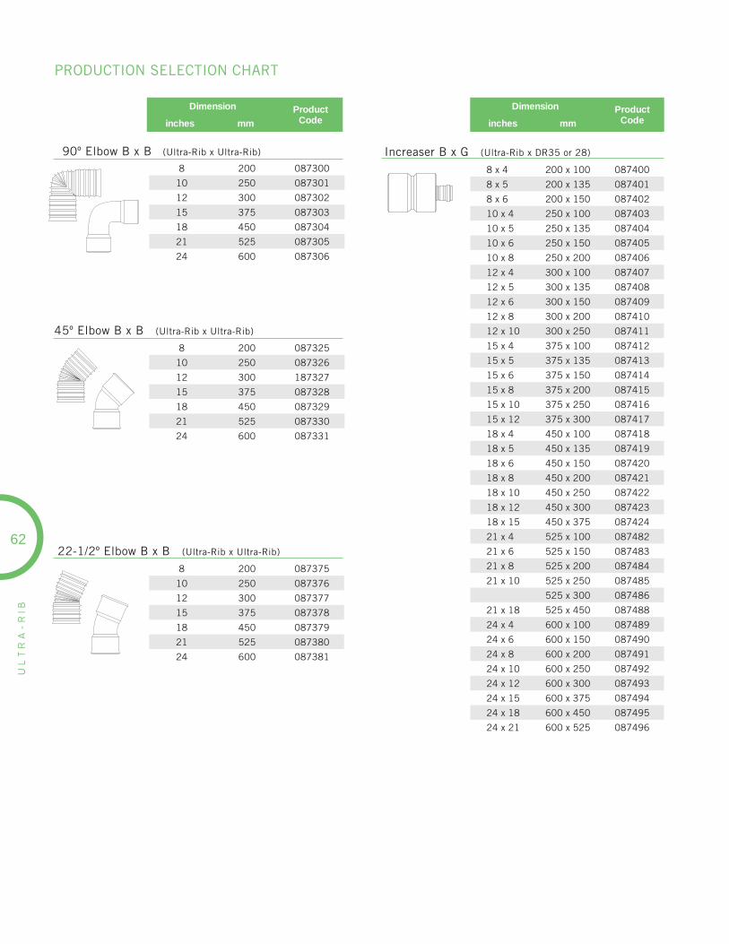
UL
TR
A-
RIB
62
8 200 087300
10 250 087301
12 300 087302
15 375 087303
18 450 087304
21 525 087305
24 600 087306
90º Elbow B x B (Ultra-Rib x Ultra-Rib)
8 200 087325
10 250 087326
12 300 187327
15 375 087328
18 450 087329
21 525 087330
24 600 087331
45º Elbow B x B (Ultra-Rib x Ultra-Rib)
Dimension ProductCodeinches mm
22-1/2º Elbow B x B (Ultra-Rib x Ultra-Rib)
8 200 087375
10 250 087376
12 300 087377
15 375 087378
18 450 087379
21 525 087380
24 600 087381
Dimension ProductCodeinches mm
8 x 4 200 x 100 087400
8 x 5 200 x 135 087401
8 x 6 200 x 150 087402
10 x 4 250 x 100 087403
10 x 5 250 x 135 087404
10 x 6 250 x 150 087405
10 x 8 250 x 200 087406
12 x 4 300 x 100 087407
12 x 5 300 x 135 087408
12 x 6 300 x 150 087409
12 x 8 300 x 200 087410
12 x 10 300 x 250 087411
15 x 4 375 x 100 087412
15 x 5 375 x 135 087413
15 x 6 375 x 150 087414
15 x 8 375 x 200 087415
15 x 10 375 x 250 087416
15 x 12 375 x 300 087417
18 x 4 450 x 100 087418
18 x 5 450 x 135 087419
18 x 6 450 x 150 087420
18 x 8 450 x 200 087421
18 x 10 450 x 250 087422
18 x 12 450 x 300 087423
18 x 15 450 x 375 087424
21 x 4 525 x 100 087482
21 x 6 525 x 150 087483
21 x 8 525 x 200 087484
21 x 10 525 x 250 087485
525 x 300 087486
21 x 18 525 x 450 087488
24 x 4 600 x 100 087489
24 x 6 600 x 150 087490
24 x 8 600 x 200 087491
24 x 10 600 x 250 087492
24 x 12 600 x 300 087493
24 x 15 600 x 375 087494
24 x 18 600 x 450 087495
24 x 21 600 x 525 087496
Increaser B x G (Ultra-Rib x DR35 or 28)
PRODUCTION SELECTION CHART
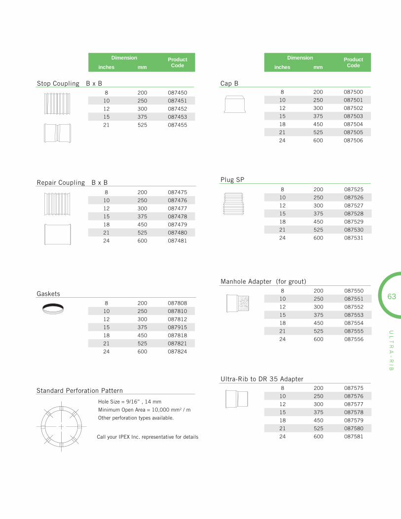
UL
TR
A-
RIB
63
Dimension ProductCodeinches mm
Stop Coupling B x B8 200 087450
10 250 087451
12 300 087452
15 375 087453
21 525 087455
Repair Coupling B x B8 200 087475
10 250 087476
12 300 087477
15 375 087478
18 450 087479
21 525 087480
24 600 087481
Gaskets8 200 087808
10 250 087810
12 300 087812
15 375 087915
18 450 087818
21 525 087821
24 600 087824
Standard Perforation Pattern
Hole Size = 9/16” , 14 mm
Minimum Open Area = 10,000 mm2 / m
Other perforation types available.
Call your IPEX Inc. representative for details
Dimension ProductCodeinches mm
8 200 087500
10 250 087501
12 300 087502
15 375 087503
18 450 087504
21 525 087505
24 600 087506
8 200 087525
10 250 087526
12 300 087527
15 375 087528
18 450 087529
21 525 087530
24 600 087531
Plug SP
Cap B
8 200 087550
10 250 087551
12 300 087552
15 375 087553
18 450 087554
21 525 087555
24 600 087556
Manhole Adapter (for grout)
8 200 087575
10 250 087576
12 300 087577
15 375 087578
18 450 087579
21 525 087580
24 600 087581
Ultra-Rib to DR 35 Adapter
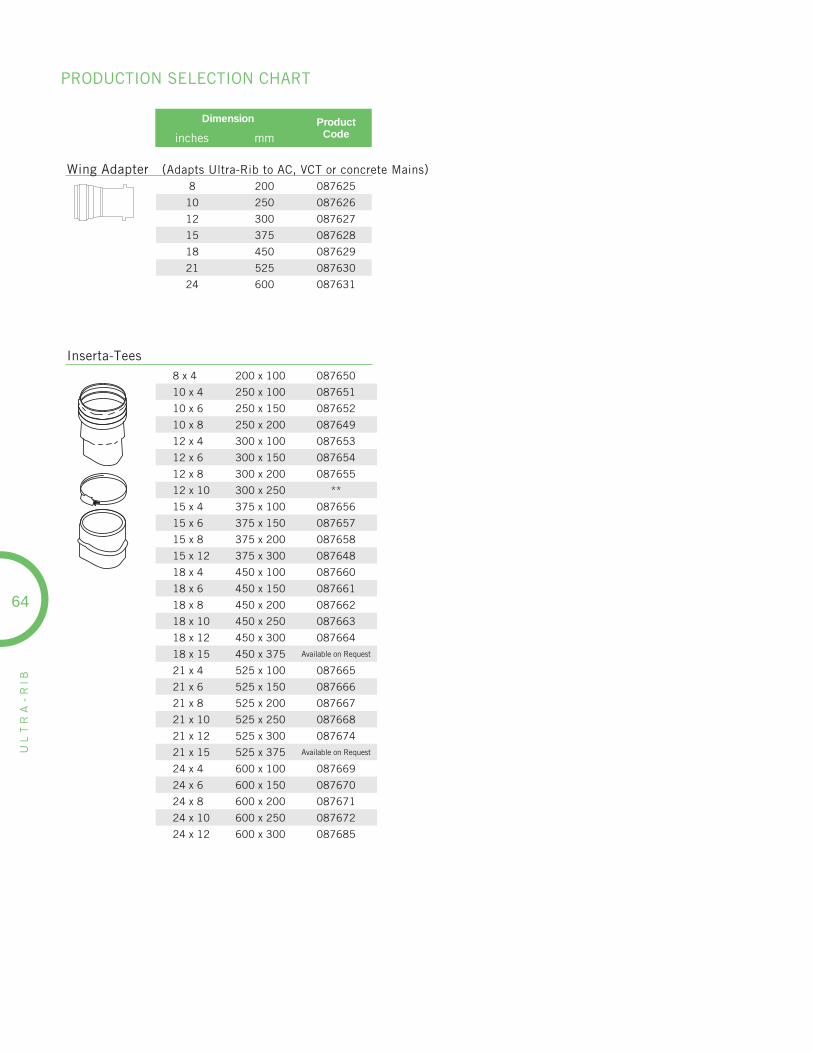
UL
TR
A-
RIB
64
PRODUCTION SELECTION CHART
Dimension ProductCodeinches mm
8 x 4 200 x 100 087650
10 x 4 250 x 100 087651
10 x 6 250 x 150 087652
10 x 8 250 x 200 087649
12 x 4 300 x 100 087653
12 x 6 300 x 150 087654
12 x 8 300 x 200 087655
12 x 10 300 x 250 **
15 x 4 375 x 100 087656
15 x 6 375 x 150 087657
15 x 8 375 x 200 087658
15 x 12 375 x 300 087648
18 x 4 450 x 100 087660
18 x 6 450 x 150 087661
18 x 8 450 x 200 087662
18 x 10 450 x 250 087663
18 x 12 450 x 300 087664
18 x 15 450 x 375 Available on Request
21 x 4 525 x 100 087665
21 x 6 525 x 150 087666
21 x 8 525 x 200 087667
21 x 10 525 x 250 087668
21 x 12 525 x 300 087674
21 x 15 525 x 375 Available on Request
24 x 4 600 x 100 087669
24 x 6 600 x 150 087670
24 x 8 600 x 200 087671
24 x 10 600 x 250 087672
24 x 12 600 x 300 087685
Wing Adapter (Adapts Ultra-Rib to AC, VCT or concrete Mains)8 200 087625
10 250 087626
12 300 087627
15 375 087628
18 450 087629
21 525 087630
24 600 087631
Inserta-Tees
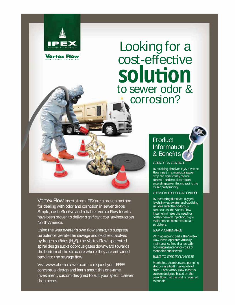
Looking for a cost-e ec vesolu onto sewer odor &
corrosion?
ProductInforma on& Bene tsCORROSION CONTROL
By oxidizing dissolved H2S, a Vortex Flow Insert in a municipal sewer drop can signi cantly reduce concrete and metal corrosion, extending sewer life and saving the municipality money.
CHEMICAL FREE ODOR CONTROL
By increasing dissolved oxygen levels in wastewater and oxidizing sul des and other odorous compounds, the Vortex Flow Insert eliminates the need for costly chemical injec on, high-maintenance bio lters and air scrubbers.
LOW MAINTENANCE
With no moving parts, the Vortex Flow Insert operates virtually maintenance free drama cally reducing maintenance costs of manholes and sewers.
BUILT-TO-SPEC FOR ANY SIZE
Manholes, chambers and pumping sta ons are built in a variety of sizes. Each Vortex Flow Insert is custom designed based on the peak ow that the unit is required to handle.
Vortex Flow Inserts from IPEX are a proven method for dealing with odor and corrosion in sewer drops. Simple, cost-e ec ve and reliable, Vortex Flow Inserts have been proven to deliver signi cant cost savings across North America.
Using the wastewater’s own ow energy to suppress turbulence, aerate the sewage and oxidize dissolved hydrogen sul des (H2S), the Vortex Flow’s patented spiral design sucks odorous gases downward towards the bo om of the structure where they are entrained back into the sewage ow.
Visit www.abe ersewer.com to request your FREE conceptual design and learn about this one- me investment, custom designed to suit your speci c sewer drop needs.
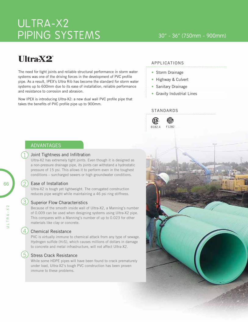
ULTRA-X2PIPING SYSTEMS 30” - 36” (750mm - 900mm)
UL
TR
A-
X2
• Storm Drainage
• Highway & Culvert
• Sanitary Drainage
• Gravity Industrial Lines
APPLICATIONS
STANDARDS
The need for tight joints and reliable structural performance in storm water systems was one of the driving forces in the development of PVC profi le pipe. As a result, IPEX’s Ultra Rib has become the standard for storm water systems up to 600mm due to its ease of installation, reliable performance and resistance to corrosion and abrasion.
Now IPEX is introducing Ultra-X2: a new dual wall PVC profi le pipe thattakes the benefi ts of PVC profi le pipe up to 900mm.
66
1
2
3
4
5
ADVANTAGES
Joint Tightness and Infi ltrationUltra-X2 has extremely tight joints. Even though it is designed as a non-pressure drainage pipe, its joints can withstand a hydrostatic pressure of 15 psi. This allows it to perform even in the toughest conditions – surcharged sewers or high groundwater conditions.
Ease of InstallationUltra-X2 is tough yet lightweight. The corrugated construction reduces pipe weight while maintaining a 46 psi ring stiffness.
Superior Flow CharacteristicsBecause of the smooth inside wall of Ultra-X2, a Manning’s number of 0.009 can be used when designing systems using Ultra-X2 pipe. This compares with a Manning’s number of up to 0.023 for other materials like clay or concrete.
Chemical ResistancePVC is virtually immune to chemical attack from any type of sewage. Hydrogen sulfi de (H2S), which causes millions of dollars in damage to concrete and metal infrastructure, will not affect Ultra-X2.
Stress Crack ResistanceWhile some HDPE pipes will have been found to crack prematurely under load, Ultra-X2’s tough PVC construction has been proven immune to these problems.
B182.4 F1282

67
UL
TR
A-
X2
NominalPipe Size OD ID Crest Wall
ThicknessLiner WallThickness
InsertionForce
in mm in mm in mm in mm in mm lbf
30 750 32.15 816.6 29.50 749.2 0.15 3.7 0.22 5.6 985
36 900 38.76 984.6 35.49 901.4 0.13 3.3 0.18 4.6 1000
DIMENSIONS
Crest Wall Thickness
Liner Wall Thickness
OD
ID
SHORT FORM SPECIFICATIONS
GENERALIPEX Ultra-X2 PVC Pipe is available in sizes 750mm and900mm (30” & 36”).
MATERIALUltra-X2 PVC Pipe shall be made of PVC compound having a cell classifi cation of 12454B as defi ned in ASTM D1784B.
PRODUCTUltra-X2 PVC pipe and fi ttings shall be certifi ed to CSA B182.4 “Profi le PVC Sewer Pipe and Fittings”, and shall meet the requirements of ASTM F794 “Standard Specifi cation forPoly (Vinyl chloride) (PVC) Profi le Gravity Sanitary Pipe andFittings Based on Controlled Inside Diameter”.
PIPE STIFFNESSPipe stiffness must be 320 kPa (46 lbs/in of sample length per inch of defl ection) at 5% vertical defl ection when tested according to ASTM D2412.
LUBRICANTAssembly of Ultra-X2 pipe shall be done in accordance with the manufacturer’s directions using only IPEX PVC pipe lubricant. Substitute lubricants shall not be used. IPEX lubricant shall be applied to the inside of the bell to be joined, to a uniform thickness for a distance inside the bell equivalent to three corrugated profi les from the outside edge.
COLOUR CODINGPipe shall be colour-coded green.

UL
TR
A-
X2
68
PRODUCTION SELECTION CHART
Dimension ProductCodeinches mm
Dimension ProductCodeinches mm
30 750 186030
36 900 186036
Ultra-X2 Profile Pipe (320 kPa (46 psi)
30 x 30 x 4 750 x 750 x 100 187000
30 x 30 x 6 750 x 750 x 150 187001
30 x 30 x 8 750 x 750 x 200 187002
30 x 30 x 10 750 x 750 x 250 187003
30 x 30 x 12 750 x 750 x 300 187004
30 x 30 x 15 750 x 750 x 375 187005
30 x 30 x 18 750 x 750 x 450 187006
30 x 30 x 21 750 x 750 x 525 187007
30 x 30 x 24 750 x 750 x 600 187008
30 x 30 x 30 750 x 750 x 750 187009
36 x 36 x 4 900 x 900 x 100 187032
36 x 36 x 6 900 x 900 x 150 187033
36 x 36 x 8 900 x 900 x 200 187034
36 x 36 x 10 900 x 900 x 250 187035
36 x 36 x 12 900 x 900 x 300 187036
36 x 36 x 15 900 x 900 x 375 187037
36 x 36 x 18 900 x 900 x 450 187038
36 x 36 x 21 900 x 900 x 525 187039
36 x 36 x 24 900 x 900 x 600 187040
36 x 36 x 30 900 x 900 x 750 187041
36 x 36 x 36 900 x 900 x 900 187042
Sewer Tee (Ultra-Rib x X2 x Swr Tee H x H x G)
30 x 30 x 8 750 x 750 x 200 187061
30 x 30 x 10 750 x 750 x 250 187062
30 x 30 x 12 750 x 750 x 300 187063
30 x 30 x 15 750 x 750 x 375 187064
30 x 30 x 18 750 x 750 x 450 187065
30 x 30 x 21 750 x 750 x 525 187066
30 x 30 x 24 750 x 750 x 600 187067
30 x 30 x 30 750 x 750 x 750 187068
36 x 36 x 8 900 x 900 x 200 187078
36 x 36 x 10 900 x 900 x 250 187079
36 x 36 x 12 900 x 900 x 300 187080
36 x 36 x 15 900 x 900 x 375 187081
36 x 36 x 18 900 x 900 x 450 187082
36 x 36 x 21 900 x 900 x 525 187083
36 x 36 x 24 900 x 900 x 600 187084
36 x 36 x 30 900 x 900 x 750 187085
36 x 36 x 36 900 x 900 x 900 187086
Sewer Tee (Ultra-Rib x X2 x Ultra-Rib x X2 H x H x H)
30 x 30 x 4 750 x 750 x 100 187010
30 x 30 x 6 750 x 750 x 150 187011
30 x 30 x 8 750 x 750 x 200 187012
30 x 30 x 10 750 x 750 x 250 187013
30 x 30 x 12 750 x 750 x 300 187014
30 x 30 x 15 750 x 750 x 375 187015
30 x 30 x 18 750 x 750 x 450 187016
30 x 30 x 21 750 x 750 x 525 187017
30 x 30 x 24 750 x 750 x 600 187018
30 x 30 x 30 750 x 750 x 750 187019
36 x 36 x 4 900 x 900 x 100 187043
36 x 36 x 6 900 x 900 x 150 187044
36 x 36 x 8 900 x 900 x 200 187045
36 x 36 x 12 900 x 900 x 300 187046
36 x 36 x 15 900 x 900 x 375 187047
36 x 36 x 18 900 x 900 x 450 187048
36 x 36 x 21 900 x 900 x 525 187049
36 x 36 x 24 900 x 900 x 600 187050
36 x 36 x 30 900 x 900 x 750 187051
36 x 36 x 36 900 x 900 x 900 187052
Sewer Wye (Ultra-Rib x X2 x Swr Wye H x H x G)
30 x 30 x 8 750 x 750 x 200 187087
30 x 30 x 10 750 x 750 x 250 187088
30 x 30 x 12 750 x 750 x 300 187089
30 x 30 x 15 750 x 750 x 375 187090
30 x 30 x 18 750 x 750 x 450 187091
30 x 30 x 21 750 x 750 x 525 187092
30 x 30 x 24 750 x 750 x 600 187093
30 x 30 x 30 750 x 750 x 750 187094
36 x 36 x 8 900 x 900 x 200 187069
36 x 36 x 10 900 x 900 x 250 187070
36 x 36 x 12 900 x 900 x 300 187071
36 x 36 x 15 900 x 900 x 375 187072
36 x 36 x 18 900 x 900 x 450 187073
36 x 36 x 21 900 x 900 x 525 187074
36 x 36 x 24 900 x 900 x 600 187075
36 x 36 x 30 900 x 900 x 750 187076
36 x 36 x 36 900 x 900 x 900 187077
Sewer Wye (Ultra-Rib x X2 x Swr Wye H x H x H)
30 750 18702036 900 187053
Ultra-X2 Cap H
UL
TR
A-
X2
69
Dimension ProductCodeinches mm
Dimension ProductCodeinches mm
30 x 4 750 x 750 x 100 187055
30 x 6 750 x 750 x 150 187056
30 x 8 750 x 750 x 200 187057
36 x 4 900 x 900 x 100 187058
36 x 6 900 x 900 x 150 187059
36 x 8 900 x 900 x 200 187060
Ultra-X2 Inserta Tees
Ultra-X2 Plug
30 w/o stop 750 187022
36 w/o stop 900 187024
30 w stop 750 187023
36 w stop 900 187025
Ultra-X2 Coupling H x H
30 750 187026
36 900 187029
Ultra-X2 22-1/2º Bends H x H
30 750 187027
36 900 187030
Ultra-X2 45º Bends H x H
30 750 187028
36 900 187031
Ultra-X2 90º Bends H x H
30 750 187021
36 900 187054
& MUCH MORE ... TECHNICAL DOCUMENTS
PRODUCT INFO
Visit our website: www.ipexna.com
DOWNLOADOUR PRESSURE PIPING SYSTEMS & SEWER PIPING SYSTEMS DESIGN MANUALS
+
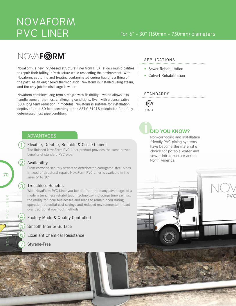
NOVAFORM PVC LINER For 6” - 30” (150mm - 750mm) diameters
NO
VA
FO
RM
P
VC
L
INE
R
• Sewer Rehabilitation
• Culvert Rehabilitation
APPLICATIONS
STANDARDS
NovaForm, a new PVC-based structural liner from IPEX, allows municipalities to repair their failing infrastructure while respecting the environment. With Novaform, capturing and treating contaminated curing liquid is a thing of the past. As an engineered thermoplastic, Novaform is installed using steam, and the only jobsite discharge is water.
Novaform combines long-term strength with fl exibility – which allows it to handle some of the most challenging conditions. Even with a conservative 50% long term reduction in modulus, Novaform is suitable for installation depths of up to 30 feet according to the ASTM F1216 calculation for a fully deteriorated host pipe condition.
1
2
3
4
5
6
7
ADVANTAGES
Flexible, Durable, Reliable & Cost-Effi cientThe fi nished NovaForm PVC Liner product provides the same proven benefi ts of standard PVC pipe.
AvailabilityFrom corroded sanitary sewers to deteriorated corrugated steel pipes in need of structural repair, NovaForm PVC Liner is available in the sizes 6" to 30".
Trenchless Benefi tsWith NovaForm PVC Liner you benefi t from the many advantages of a modern trenchless rehabilitation technology including: time savings, the ability for local businesses and roads to remain open during operation, potential cost savings and reduced environmental impact over traditional open-cut methods.
Factory Made & Quality Controlled
Smooth Interior Surface
Excellent Chemical Resistance
Styrene-Free
70
F1504
i DID YOU KNOW?Non-corroding and installation friendly PVC piping systems have become the material of choice for potable water and sewer infrastructure across North America.
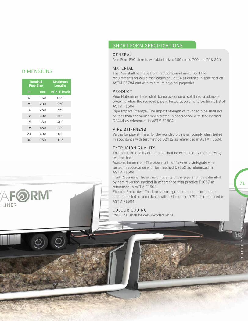
71
NO
VA
FO
RM
P
VC
L
INE
R
NominalPipe Size
MaximumLengths
in mm (4’ x 4’ Reel)
6 150 1350
8 200 950
10 250 550
12 300 420
15 350 400
18 450 220
24 600 150
30 750 125
DIMENSIONS
SHORT FORM SPECIFICATIONS
GENERALNovaForm PVC Liner is available in sizes 150mm to 700mm (6" & 30").
MATERIALThe Pipe shall be made from PVC compound meeting all the requirements for cell classifi cation of 12334 as defi ned in specifi cation ASTM D1784 and with minimum physical properties.
PRODUCTPipe Flattening: There shall be no evidence of splitting, cracking or breaking when the rounded pipe is tested according to section 11.3 of ASTM F1504.Pipe Impact Strength: The impact strength of rounded pipe shall not be less than the values when tested in accordance with test method D2444 as referenced in ASTM F1504.
PIPE STIFFNESSValues for pipe stiffness for the rounded pipe shall comply when tested in accordance with test method D2412 as referenced in ASTM F1504.
EXTRUSION QUALITYThe extrusion quality of the pipe shall be evaluated by the following test methods:Acetone Immersion: The pipe shall not fl ake or disintegrate when tested in accordance with test method D2152 as referenced in ASTM F1504.Heat Reversion: The extrusion quality of the pipe shall be estimated by heat reversion method in accordance with practice F1057 as referenced in ASTM F1504.Flexural Properties: The fl exural strength and modulus of the pipe shall be tested in accordance with test method D790 as referenced in ASTM F1504.
COLOUR CODINGPVC Liner shall be colour-coded white.
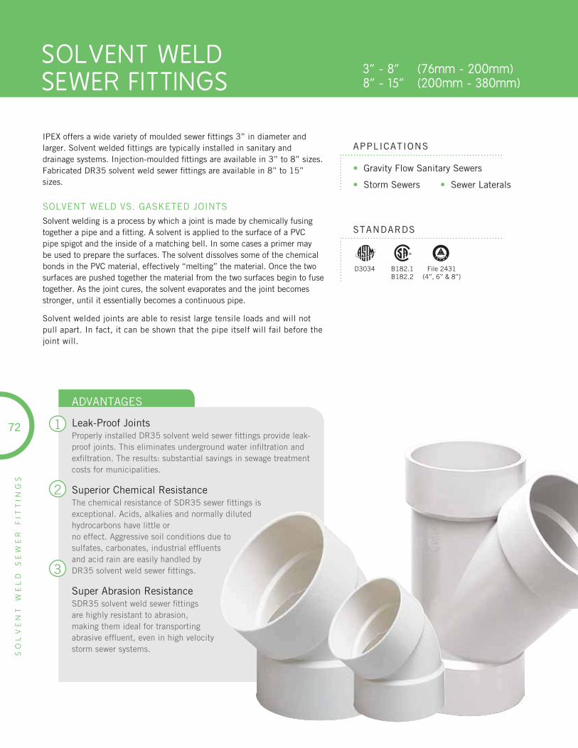
SOLVENT WELDSEWER FITTINGS
3” - 8” (76mm - 200mm) 8” - 15” (200mm - 380mm)
SO
LV
EN
T
WE
LD
S
EW
ER
F
ITT
ING
S
• Gravity Flow Sanitary Sewers
• Storm Sewers • Sewer Laterals
APPLICATIONS
STANDARDS
IPEX offers a wide variety of moulded sewer fi ttings 3” in diameter and larger. Solvent welded fi ttings are typically installed in sanitary and drainage systems. Injection-moulded fi ttings are available in 3” to 8” sizes. Fabricated DR35 solvent weld sewer fi ttings are available in 8” to 15” sizes.
SOLVENT WELD VS. GASKETED JOINTS
Solvent welding is a process by which a joint is made by chemically fusing together a pipe and a fi tting. A solvent is applied to the surface of a PVC pipe spigot and the inside of a matching bell. In some cases a primer may be used to prepare the surfaces. The solvent dissolves some of the chemical bonds in the PVC material, effectively “melting” the material. Once the two surfaces are pushed together the material from the two surfaces begin to fuse together. As the joint cures, the solvent evaporates and the joint becomes stronger, until it essentially becomes a continuous pipe.
Solvent welded joints are able to resist large tensile loads and will not pull apart. In fact, it can be shown that the pipe itself will fail before the joint will.
1
2
3
ADVANTAGES
Leak-Proof JointsProperly installed DR35 solvent weld sewer fi ttings provide leak-proof joints. This eliminates underground water infi ltration and exfi ltration. The results: substantial savings in sewage treatment costs for municipalities.
Superior Chemical ResistanceThe chemical resistance of SDR35 sewer fi ttings is exceptional. Acids, alkalies and normally diluted hydrocarbons have little orno effect. Aggressive soil conditions due to sulfates, carbonates, industrial effl uents and acid rain are easily handled by DR35 solvent weld sewer fi ttings.
Super Abrasion ResistanceSDR35 solvent weld sewer fi ttings are highly resistant to abrasion, making them ideal for transporting abrasive effl uent, even in high velocity storm sewer systems.
72
D3034 B182.1B182.2
File 2431(4”, 6” & 8”)
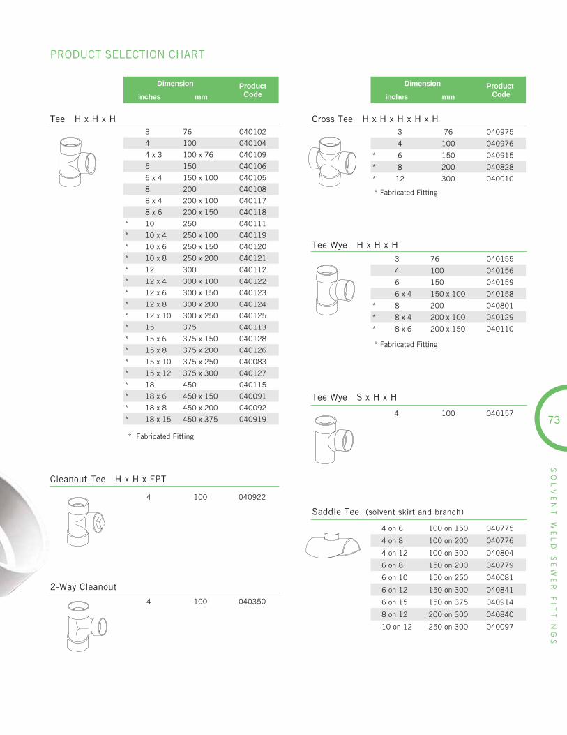
73
SO
LV
EN
T
WE
LD
S
EW
ER
F
ITT
ING
S
PRODUCT SELECTION CHART
Dimension ProductCodeinches mm
3 76 040102
4 100 040104
4 x 3 100 x 76 040109
6 150 040106
6 x 4 150 x 100 040105
8 200 040108
8 x 4 200 x 100 040117
8 x 6 200 x 150 040118
* 10 250 040111
* 10 x 4 250 x 100 040119
* 10 x 6 250 x 150 040120
* 10 x 8 250 x 200 040121
* 12 300 040112
* 12 x 4 300 x 100 040122
* 12 x 6 300 x 150 040123
* 12 x 8 300 x 200 040124
* 12 x 10 300 x 250 040125
* 15 375 040113
* 15 x 6 375 x 150 040128
* 15 x 8 375 x 200 040126
* 15 x 10 375 x 250 040083
* 15 x 12 375 x 300 040127
* 18 450 040115
* 18 x 6 450 x 150 040091
* 18 x 8 450 x 200 040092
* 18 x 15 450 x 375 040919
* Fabricated Fitting
Tee H x H x H Cross Tee H x H x H x H x H
Dimension Product Codeinches mm
3 76 040975
4 100 040976
* 6 150 040915
* 8 200 040828
* 12 300 040010
* Fabricated Fitting
Cleanout Tee H x H x FPT
4 100 040922
2-Way Cleanout
4 100 040350
Tee Wye H x H x H3 76 040155
4 100 040156
6 150 040159
6 x 4 150 x 100 040158
* 8 200 040801
* 8 x 4 200 x 100 040129
* 8 x 6 200 x 150 040110
* Fabricated Fitting
Tee Wye S x H x H
4 100 040157
Saddle Tee (solvent skirt and branch)
4 on 6 100 on 150 040775
4 on 8 100 on 200 040776
4 on 12 100 on 300 040804
6 on 8 150 on 200 040779
6 on 10 150 on 250 040081
6 on 12 150 on 300 040841
6 on 15 150 on 375 040914
8 on 12 200 on 300 040840
10 on 12 250 on 300 040097
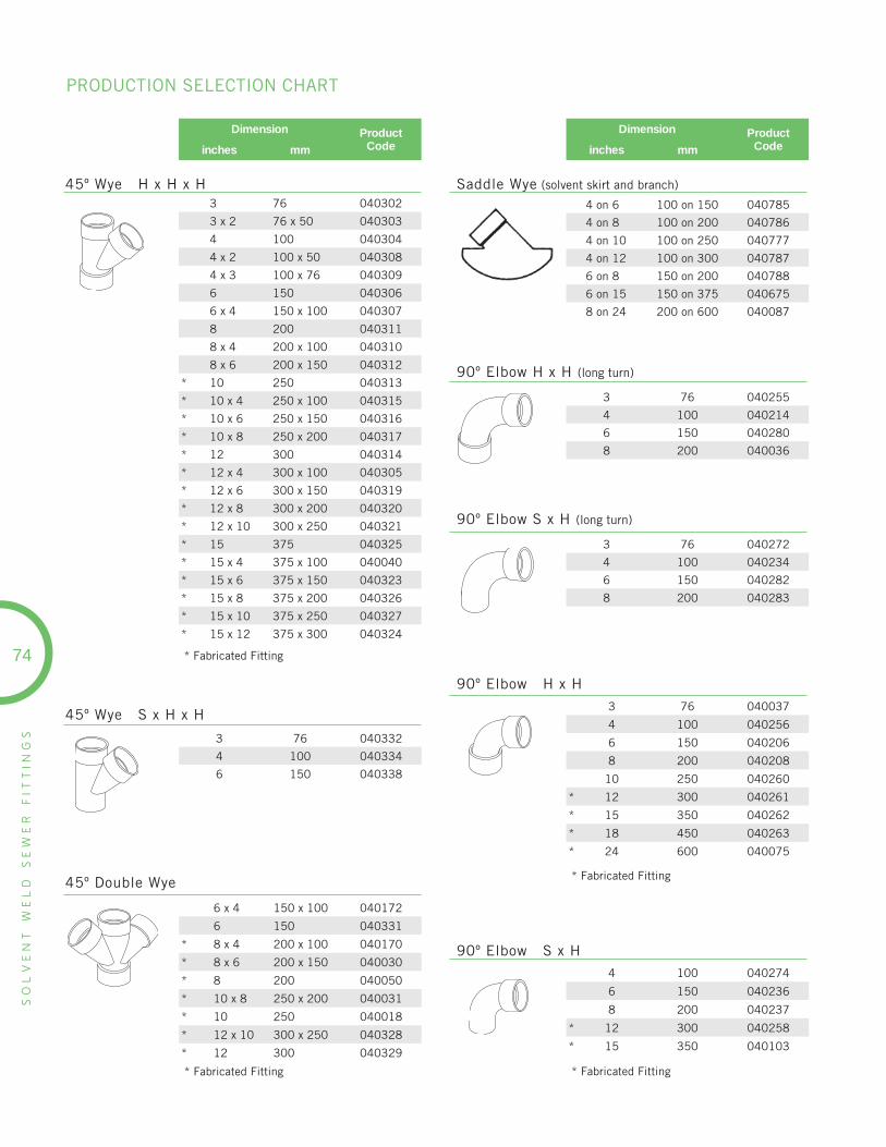
SO
LV
EN
T
WE
LD
S
EW
ER
F
ITT
ING
S
74
Dimension ProductCodeinches mm
3 76 040302
3 x 2 76 x 50 040303
4 100 040304
4 x 2 100 x 50 040308
4 x 3 100 x 76 040309
6 150 040306
6 x 4 150 x 100 040307
8 200 040311
8 x 4 200 x 100 040310
8 x 6 200 x 150 040312
* 10 250 040313
* 10 x 4 250 x 100 040315
* 10 x 6 250 x 150 040316
* 10 x 8 250 x 200 040317
* 12 300 040314
* 12 x 4 300 x 100 040305
* 12 x 6 300 x 150 040319
* 12 x 8 300 x 200 040320
* 12 x 10 300 x 250 040321
* 15 375 040325
* 15 x 4 375 x 100 040040
* 15 x 6 375 x 150 040323
* 15 x 8 375 x 200 040326
* 15 x 10 375 x 250 040327
* 15 x 12 375 x 300 040324
* Fabricated Fitting
45º Wye H x H x H Saddle Wye (solvent skirt and branch)
Dimension ProductCodeinches mm
4 on 6 100 on 150 040785
4 on 8 100 on 200 040786
4 on 10 100 on 250 040777
4 on 12 100 on 300 040787
6 on 8 150 on 200 040788
6 on 15 150 on 375 040675
8 on 24 200 on 600 040087
45º Wye S x H x H
3 76 040332
4 100 040334
6 150 040338
90º Elbow H x H (long turn)
3 76 040255
4 100 040214
6 150 040280
8 200 040036
90º Elbow S x H (long turn)
3 76 040272
4 100 040234
6 150 040282
8 200 040283
90º Elbow H x H
3 76 040037
4 100 040256
6 150 040206
8 200 040208
10 250 040260
* 12 300 040261
* 15 350 040262
* 18 450 040263
* 24 600 040075
* Fabricated Fitting
90º Elbow S x H4 100 040274
6 150 040236
8 200 040237
* 12 300 040258
* 15 350 040103
* Fabricated Fitting
45º Double Wye
6 x 4 150 x 100 040172
6 150 040331
* 8 x 4 200 x 100 040170
* 8 x 6 200 x 150 040030
* 8 200 040050
* 10 x 8 250 x 200 040031
* 10 250 040018
* 12 x 10 300 x 250 040328
* 12 300 040329
* Fabricated Fitting
PRODUCTION SELECTION CHART
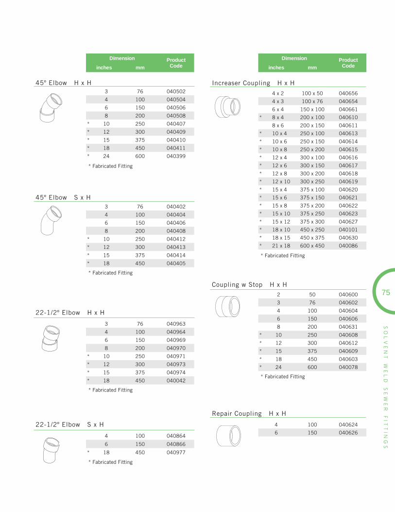
SO
LV
EN
T
WE
LD
S
EW
ER
F
ITT
ING
S
75
Dimension ProductCodeinches mm
4 x 2 100 x 50 040656
4 x 3 100 x 76 040654
6 x 4 150 x 100 040661
* 8 x 4 200 x 100 040610
8 x 6 200 x 150 040611
* 10 x 4 250 x 100 040613
* 10 x 6 250 x 150 040614
* 10 x 8 250 x 200 040615
* 12 x 4 300 x 100 040616
* 12 x 6 300 x 150 040617
* 12 x 8 300 x 200 040618
* 12 x 10 300 x 250 040619
* 15 x 4 375 x 100 040620
* 15 x 6 375 x 150 040621
* 15 x 8 375 x 200 040622
* 15 x 10 375 x 250 040623
* 15 x 12 375 x 300 040627
* 18 x 10 450 x 250 040101
* 18 x 15 450 x 375 040630
* 21 x 18 600 x 450 040086
* Fabricated Fitting
Increaser Coupling H x H3 76 040502
4 100 040504
6 150 040506
8 200 040508
* 10 250 040407
* 12 300 040409
* 15 375 040410
* 18 450 040411
* 24 600 040399
* Fabricated Fitting
45º Elbow H x H
3 76 040402
4 100 040404
6 150 040406
8 200 040408
* 10 250 040412
* 12 300 040413
* 15 375 040414
* 18 450 040405
* Fabricated Fitting
45º Elbow S x H
3 76 040963
4 100 040964
6 150 040969
8 200 040970
* 10 250 040971
* 12 300 040973
* 15 375 040974
* 18 450 040042
* Fabricated Fitting
22-1/2º Elbow H x H
4 100 040864
6 150 040866
* 18 450 040977
* Fabricated Fitting
22-1/2º Elbow S x H
2 50 040600
3 76 040602
4 100 040604
6 150 040606
8 200 040631
* 10 250 040608
* 12 300 040612
* 15 375 040609
* 18 450 040603
* 24 600 040078
* Fabricated Fitting
Coupling w Stop H x H
4 100 040624
6 150 040626
Repair Coupling H x H
Dimension ProductCodeinches mm

SO
LV
EN
T
WE
LD
S
EW
ER
F
ITT
ING
S
76
6 x 4 150 x 100 040939
8 x 4 200 x 100 040897
8 x 6 200 x 150 040940
* 10 x 4 250 x 100 040898
10 x 6 250 x 150 040899
* 10 x 8 250 x 200 040900
* 12 x 6 300 x 150 040902
* 12 x 8 300 x 200 040903
* 12 x 10 300 x 250 040904
* 15 x 10 375 x 250 040905
* 15 x 12 375 x 300 040906
* 18 x 12 450 x 300 040913
* 18 x 15 450 x 375 040908
* Fabricated Fitting
Dimension ProductCodeinches mm
Extended Bushing S x H
4 x 3 100 x 76 040933
6 x 4 150 x 100 040896
Reducer Bushing S x H
4 x 1-1/2 100 x 38 040416
Reducer Bushing S x FPT
4 100 040728
4 long 100 long 040808
6 150 040729
* 18 450 040340
* Fabricated Fitting
Adapter (Sewer Spigot x DWV Hub)
3 x 1-1/2 76 x 38 040932
3 x 2 76 x 50 040341
4 x 2 100 x 50 040935
Adapter Bushing (Sewer Spigot x DWV Hub)
Dimension ProductCodeinches mm
4 x 3 100 x 76 040934
6 x 4 150 x 100 040941
Extended Adapter Bushing (Sewer Spigot x DWV Hub)
4 100 040342
12 300 040207
Adapter Sleeve (Sewer Hub x DWV Spigot)
4 x 4 100 x 100 040704
Cast Iron Spigot Adapter H x H
4 x 3 100 x 76 040655
4 x 4 100 x 100 040725
6 x 4 150 x 100 040727
6 x 6 150 x 150 040756
Adapter Coupling (Sewer Hub x DWV Hub)
4 100 040723
Male Adapter Hub x MPT
3 76 040948
4 100 040949
6 150 040952
8 200 040945
* 10 250 040946
* 12 300 040947
* Fabricated Fitting
Female Adapter Hub x FPT
PRODUCTION SELECTION CHART
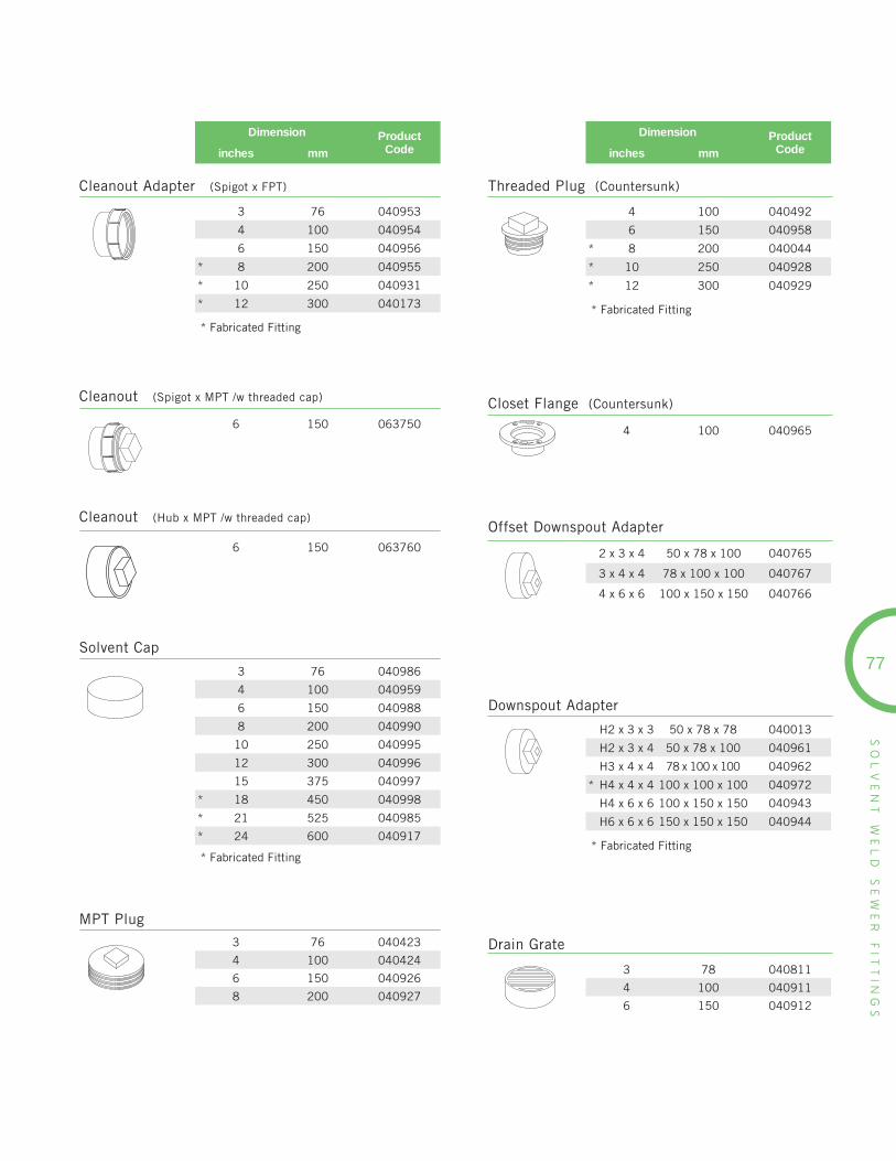
SO
LV
EN
T
WE
LD
S
EW
ER
F
ITT
ING
S
77
Dimension ProductCodeinches mm
4 100 040492
6 150 040958
* 8 200 040044
* 10 250 040928
* 12 300 040929
* Fabricated Fitting
Threaded Plug (Countersunk)
3 76 040953
4 100 040954
6 150 040956
* 8 200 040955
* 10 250 040931
* 12 300 040173
* Fabricated Fitting
Dimension ProductCodeinches mm
Cleanout Adapter (Spigot x FPT)
6 150 063750
Cleanout (Spigot x MPT /w threaded cap)
6 150 063760
Cleanout (Hub x MPT /w threaded cap)
3 76 040986
4 100 040959
6 150 040988
8 200 040990
10 250 040995
12 300 040996
15 375 040997
* 18 450 040998
* 21 525 040985
* 24 600 040917
* Fabricated Fitting
Solvent Cap
3 76 040423
4 100 040424
6 150 040926
8 200 040927
MPT Plug
4 100 040965
Closet Flange (Countersunk)
2 x 3 x 4 50 x 78 x 100 040765
3 x 4 x 4 78 x 100 x 100 040767
4 x 6 x 6 100 x 150 x 150 040766
Offset Downspout Adapter
H2 x 3 x 3 50 x 78 x 78 040013
H2 x 3 x 4 50 x 78 x 100 040961
H3 x 4 x 4 78 x 100 x 100 040962
* H4 x 4 x 4 100 x 100 x 100 040972
H4 x 6 x 6 100 x 150 x 150 040943
H6 x 6 x 6 150 x 150 x 150 040944
* Fabricated Fitting
Downspout Adapter
3 78 040811
4 100 040911
6 150 040912
Drain Grate

NEXT GENERATIONNEXT GENERATIONSTORMWATERSTORMWATERFLOW CONTROLFLOW CONTROL
NEXT GENERATIONSTORMWATERFLOW CONTROL
CONTROL BACK-UPS & CSO’SDURING PEAK FLOW EVENTS WITH TEMPESTTM INLET CONTROL DEVICES
TEMPEST HF
The standard Tempest HF system allows a near constant discharge rate to be set and eliminates the passage of odors and floatables and allows for debris and sediment to collect in the structure.
TEMPEST MHF The Tempest MHF is a standard orificeplate device designed to allow a specified flow volume through the outlet pipe at a specified head.
TEMPEST HF SUMP
The Tempest HF SUMP system is designed for catch basins & manholes in which there is no sump or the outlet
pipe is too low to install a standard Tempest device.
TEMPEST LMF
The Tempest LMF system features a vortex inlet design that allows a low flow rate to be set and eliminates the passage of odors and floatables and allows for debris and sediment to collect in the structure.

Proven in tough North American climates for more than 30 years, IPEX
AWWA municipal pressure pipe & fi ttings are manufactured from custom
engineered PVC compounds to deliver superior strength and corrosion
resistance, along with the ability to fl ex without damage – even under high
traffi c loads and in deep burial applications. IPEX AWWA PVC pressure
pipe offers long-term performance unmatched by any other pipe material.
PRESSURE PIPE & FITTINGS
Blue Brute Piping Systems 6
Blue Brute Fitting Systems 10
Bionax PVCO Pressure Piping Systems 14
IPEX Centurion Piping Systems 16
IPEX Fusible 24
TerraBrute CR 26
CycleTough Piping Systems 30
For unique municipal applications IPEX has developed equally unique
solutions. From advanced odour control and improved wastewater quality
products such as our Vortex Flow™ to Tempest Inlet Control Devices, IPEX
has your engineered solution.
Vortex Flow Inserts 80
LifeSaver Manhole 82& Catchbasin Adjustment Units
Storm Sewer Inlet Controls 84
SPECIALTYPRODUCTS
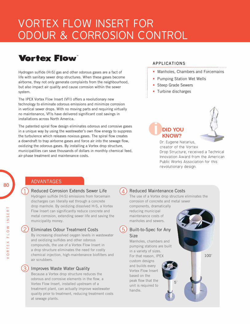
PRODUCT TITLEPRODUCT TITLE 4” - 16” (100mm - 300mm)
APPLICATIONS
80
VO
RT
EX
F
LO
W
INS
ER
T
• Manholes, Chambers and Forcemains
• Pumping Station Wet Wells
• Steep Grade Sewers
• Turbine discharges
APPLICATIONS
Hydrogen sulfi de (H2S) gas and other odorous gases are a fact of life with sanitary sewer drop structures. When these gases become airborne, they not only generate complaints from the neighbourhood, but also impact air quality and cause corrosion within the sewer system.
The IPEX Vortex Flow Insert (VFI) offers a revolutionary new technology to eliminate odorous emissions and minimize corrosion in vertical sewer drops. With no moving parts and requiring virtually no maintenance, VFIs have delivered signifi cant cost savings in installations across North America.
The patented spiral fl ow design eliminates odorous and corrosive gases in a unique way by using the wastewater’s own fl ow energy to suppress the turbulence which releases noxious gases. The spiral fl ow creates a downdraft to trap airborne gases and force air into the sewage fl ow, oxidizing the odorous gases. By installing a Vortex drop structure, municipalities can save thousands of dollars in monthly chemical feed, air-phase treatment and maintenance costs.
1
2
3
ADVANTAGES
Reduced Corrosion Extends Sewer LifeHydrogen sulfi de (H2S) emissions from forcemain discharges can literally eat through a concrete drop manhole. By oxidizing dissolved H2S, a Vortex Flow Insert can signifi cantly reduce concrete and metal corrosion, extending sewer life and saving the municipality money.
Eliminates Odour Treatment CostsBy increasing dissolved oxygen levels in wastewater and oxidizing sulfi des and other odorous compounds, the use of a Vortex Flow Insert in a drop structure eliminates the need for costly chemical injection, high-maintenance biofi lters and air scrubbers.
Improves Waste Water QualityBecause a Vortex drop structure reduces the odorous and corrosive elements in the fl ow, aVortex Flow Insert, installed upstream of a treatment plant, can actually improve wastewater quality prior to treatment, reducing treatment costs at sewage plants.
Reduced Maintenance CostsThe use of a Vortex drop structure eliminates the corrosion of concrete and metal sewercomponents, dramatically reducing municipal maintenance costs of manholes and sewers.
Built-to-Spec for Any SizeManholes, chambers and pumping stations are built in a variety of sizes.For that reason, IPEX custom designs and builds every Vortex Flow Insert based on the peak fl ow that the unit is required to handle.
4
5
VORTEX FLOW INSERT FORODOUR & CORROSION CONTROL
DID YOU KNOW?
Dr. Eugene Natarius, creator of the Vortex Drop Structure, received a Technical Innovation Award from the American Public Works Association for this revolutionary design.
i
80
100´
5´
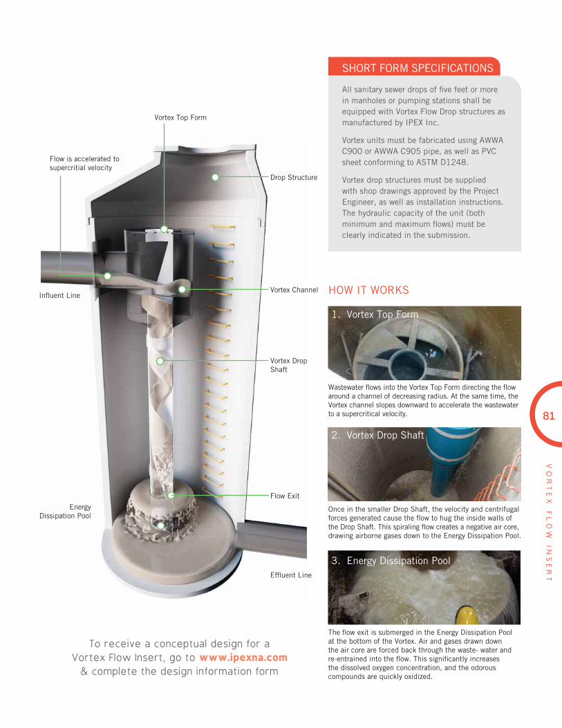
8181
VO
RT
EX
F
LO
W
INS
ER
T
The fl ow exit is submerged in the Energy Dissipation Pool at the bottom of the Vortex. Air and gases drawn down the air core are forced back through the waste- water and re-entrained into the fl ow. This signifi cantly increases the dissolved oxygen concentration, and the odorous compounds are quickly oxidized.
To receive a conceptual design for a Vortex Flow Insert, go to www.ipexna.com
& complete the design information form
HOW IT WORKS
SHORT FORM SPECIFICATIONS
All sanitary sewer drops of fi ve feet or more in manholes or pumping stations shall be equipped with Vortex Flow Drop structures as manufactured by IPEX Inc.
Vortex units must be fabricated using AWWA C900 or AWWA C905 pipe, as well as PVC sheet conforming to ASTM D1248.
Vortex drop structures must be supplied with shop drawings approved by the Project Engineer, as well as installation instructions. The hydraulic capacity of the unit (both minimum and maximum fl ows) must be clearly indicated in the submission.
1. Vortex Top Form
2. Vortex Drop Shaft
3. Energy Dissipation Pool
Wastewater fl ows into the Vortex Top Form directing the fl ow around a channel of decreasing radius. At the same time, the Vortex channel slopes downward to accelerate the wastewater to a supercritical velocity.
Once in the smaller Drop Shaft, the velocity and centrifugal forces generated cause the fl ow to hug the inside walls of the Drop Shaft. This spiraling fl ow creates a negative air core, drawing airborne gases down to the Energy Dissipation Pool.
Infl uent Line
Drop Structure
Vortex Channel
Vortex Drop Shaft
Flow Exit
Effl uent Line
EnergyDissipation Pool
Vortex Top Form
Flow is accelerated to supercritial velocity
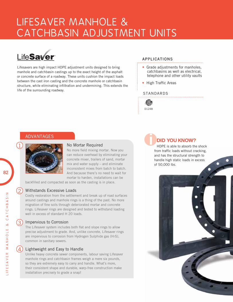
PRODUCT TITLEPRODUCT TITLE 4” - 16” (100mm - 300mm)
APPLICATIONS
82
LIFESAVER MANHOLE &CATCHBASIN ADJUSTMENT UNITS
LIF
ES
AV
ER
M
AN
HO
LE
&
C
AT
CH
BA
SIN
• Grade adjustments for manholes, catchbasins as well as electrical, telephone and other utility vaults
• High Traffi c Areas
APPLICATIONS
STANDARDS
Lifesavers are high impact HDPE adjustment units designed to bring manhole and catchbasin castings up to the exact height of the asphalt or concrete surface of a roadway. These units cushion the impact loads between the cast iron casting and the concrete manhole or catchbasin structure, while eliminating infi ltration and undermining. This extends the life of the surrounding roadway.
82
D1248
DID YOU KNOW?HDPE is able to absorb the shock
from traffi c loads without cracking, and has the structural strength to handle high static loads in excess of 50,000 lbs.
i1
2
3
4
ADVANTAGES
No Mortar RequiredNo more fi eld mixing mortar. Now you can reduce overhead by eliminating your concrete mixer, trailers of sand, mortar mix and water supply – and eliminate inconsistent mixes from batch to batch. And because there’s no need to wait for mortar to harden, installations can be
backfi lled and compacted as soon as the casting is in place.
Withstands Excessive LoadsCostly restoration from the settlement and break up of road surfaces around castings and manhole rings is a thing of the past. No more migration of fi ne soils through deteriorated mortar and concrete rings. Lifesaver rings are designed and tested to withstand loading well in excess of standard H 20 loads.
Impervious to CorrosionThe Lifesaver system includes both fl at and slope rings to allow precise adjustment to grade. And, unlike concrete, Lifesaver rings are impervious to corrosion from Hydrogen Sulphide gas (H2S),common in sanitary sewers.
Lightweight and Easy to HandleUnlike heavy concrete sewer components, labour saving Lifesaver manhole rings and catchbasin frames weigh a mere six pounds, so they are extremely easy to carry and handle. What’s more, their consistent shape and durable, warp-free construction make installation precisely to grade a snap!

8383
LIF
ES
AV
ER
M
AN
HO
LE
&
C
AT
CH
BA
SIN
Description Product Code
3% Sloped Catchbasin Adjustment Unit 074330
6% Sloped Catchbasin Adjustment Unit 074157
1-1/2” Flat Catchbasin Adjustment Unit 074075
2” Flat Catchbasin Adjustment Unit 074076
2-3/4” Flat Catchbasin Adjustment Unit 074077
PRODUCT SELECTION CHART
Manhole Adjustment Units
Catchbasin Adjustment Units (24” x 24”)
Description Product Code
1% Sloped Catchbasin Adjustment Unit 074997
1-1/2” Flat Catchbasin Adjustment Unit 074994
2” Flat Catchbasin Adjustment Unit 074995
2-3/4” Flat Catchbasin Adjustment Unit 074996
Catchbasin Adjustment Units (24” x 36”)
Size Description Product Code
24 x 4” Flat Manhole Adjustment Unit 074140
24 x 2” Flat Manhole Adjustment Unit 074141
24 x 1-1/2” Flat Manhole Adjustment Unit 074142
24 x 1-1/4” Flat Manhole Adjustment Unit 074143
24 x 1-1/2” Sloped Adjustment Unit 074144
27 x 2” Flat Manhole Adjustment Unit 074145
27 x 1-1/2” Flat Manhole Adjustment Unit 074146
27 x 1-1/4” Flat Manhole Adjustment Unit 074147
27 x 1-1/2” Sloped Adjustment Units 074148
27 x 4” Flat Manhole Adjustment Unit 074245
30 x 2-1/4” Flat Manhole Adjustment Unit 074001
30 x 4” Flat Manhole Adjustment Unit 074002
30 x 1-1/2” Sloped Adjustment Unit 074003
30 x 1-1/2” Flat Manhole Adjustment Unit 074007
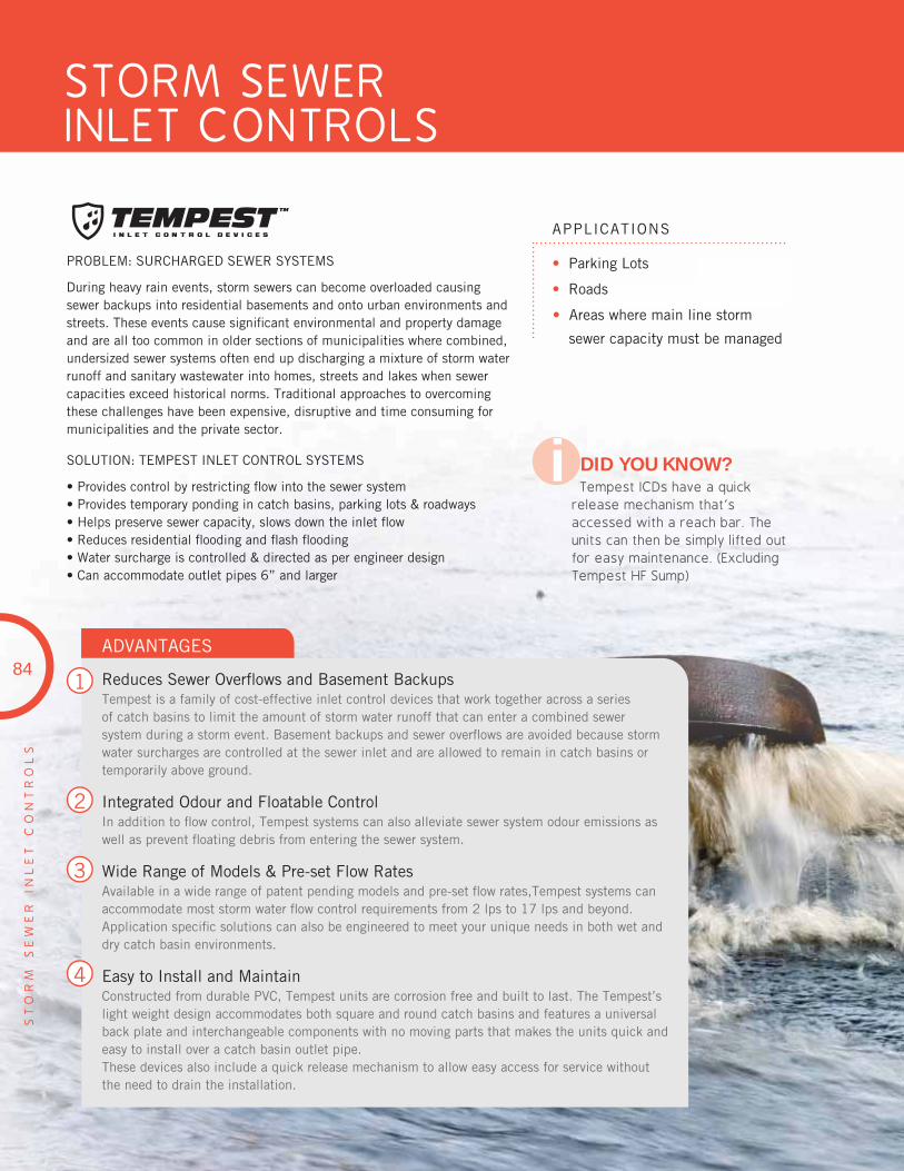
PRODUCT TITLEPRODUCT TITLE 4” - 16” (100mm - 300mm)
PA
GE
T
ITL
E
EN
TE
R
HE
RE
APPLICATIONS
STANDARDS
Designed for municipal applications, Blue Brute® systems deliver superior strength with corrosion resistant performance and the ability to fl exwithout damage.
IPEX municipal pressure piping systems are made with a high-strength, high-impact PVC compound, allowing them to perform even under high traffi c loads and deep burial conditions.
Blue Brute fi ttings are injection molded and are even tougher than the pipe. Injection molded Blue Brute fi ttings have a wall thickness 125% larger than SDR18 pipe, and custom-made fabricated fi ttings are wrapped with a tough layer of fi berglass for extra protection.
1
2
3
4
5
ADVANTAGES
ADV SubheadsADV texts
ADV SubheadsADV texts
84
STORM SEWER INLET CONTROLS
ST
OR
M
SE
WE
R
INL
ET
C
ON
TR
OL
S
APPLICATIONS
PROBLEM: SURCHARGED SEWER SYSTEMS
During heavy rain events, storm sewers can become overloaded causing sewer backups into residential basements and onto urban environments and streets. These events cause signifi cant environmental and property damage and are all too common in older sections of municipalities where combined, undersized sewer systems often end up discharging a mixture of storm water runoff and sanitary wastewater into homes, streets and lakes when sewer capacities exceed historical norms. Traditional approaches to overcoming these challenges have been expensive, disruptive and time consuming for municipalities and the private sector.
SOLUTION: TEMPEST INLET CONTROL SYSTEMS
• Provides control by restricting fl ow into the sewer system • Provides temporary ponding in catch basins, parking lots & roadways • Helps preserve sewer capacity, slows down the inlet fl ow • Reduces residential fl ooding and fl ash fl ooding • Water surcharge is controlled & directed as per engineer design• Can accommodate outlet pipes 6” and larger
1
2
3
4
ADVANTAGES
Reduces Sewer Overfl ows and Basement BackupsTempest is a family of cost-effective inlet control devices that work together across a series of catch basins to limit the amount of storm water runoff that can enter a combined sewer system during a storm event. Basement backups and sewer overfl ows are avoided because storm water surcharges are controlled at the sewer inlet and are allowed to remain in catch basins or temporarily above ground.
Integrated Odour and Floatable ControlIn addition to fl ow control, Tempest systems can also alleviate sewer system odour emissions as well as prevent fl oating debris from entering the sewer system.
Wide Range of Models & Pre-set Flow RatesAvailable in a wide range of patent pending models and pre-set fl ow rates,Tempest systems can accommodate most storm water fl ow control requirements from 2 lps to 17 lps and beyond. Application specifi c solutions can also be engineered to meet your unique needs in both wet and dry catch basin environments.
Easy to Install and MaintainConstructed from durable PVC, Tempest units are corrosion free and built to last. The Tempest’s light weight design accommodates both square and round catch basins and features a universal back plate and interchangeable components with no moving parts that makes the units quick and easy to install over a catch basin outlet pipe.These devices also include a quick release mechanism to allow easy access for service without the need to drain the installation.
84
• Parking Lots
• Roads
• Areas where main line storm
sewer capacity must be managed
DID YOU KNOW?Tempest ICDs have a quick
release mechanism that’s accessed with a reach bar. The units can then be simply lifted out for easy maintenance. (Excluding Tempest HF Sump)
i

85
PA
GE
T
ITL
E
EN
TE
R
HE
RE
85
ST
OR
M
SE
WE
R
INL
ET
C
ON
TR
OL
S
THE TEMPEST FAMILY OF SYSTEMS
TEMPEST LMF
Restricts:✓ Flow✓ Odours✓ Floatables
LOW to MODERATE FLOW RATES2 L/s (32 GPM) – 17 L/s (270 GPM) 14 pre-set fl ow rates
The Tempest LMF system features a vortex inlet design that allows a low fl ow rate to be set and eliminates the passage of odours and fl oatables and allows for debris and sediment to collect in the structure.
HIGH FLOW RATES 15L/s (240 GPM) or greater 5 pre-set fl ow rates
The standard Tempest HF system allows a near constant discharge rate to be set and eliminates the passage of odours and fl oatables and allows for debris and sediment to collect in the structure.
The Tempest HF SUMP system is designed for catch basins & manholes in which there is no sump or the outlet pipe is too low to install a standard Tempest devices.
MEDIUM TO HIGH FLOW RATES 9L/s (143 GPM) or greater Specifi ed pre-set fl ow rates
The Tempest MHF is a standard orifi ce plate device designed to allow a specifi ed fl ow volume through the outlet pipe at a specifi ed head.
TEMPEST HF & HF SUMP
Restricts:✓ Flow✓ Odours✓ Floatables
TEMPEST MHF
Restricts:✓ Flow
AVAILABLE FOR BOTH SQUARE AND ROUND CATCH BASINS(excluding Tempest HF Sump)
UNIVERSAL BACK PLATES
For square catch basins
For roundcatch basins

86
ST
OR
M
SE
WE
R
INL
ET
C
ON
TR
OL
S
86
Low to medium fl ow
Restricts fl ow to 2 Lps - 17 Lps
14 preset fl ow rates
Floatable and odour control
Supplied with neoprene gasket
Description
LMF ICD
Description
Square catch basin adapter
Round catch basin adapter
Hi fl ow
Restricts fl ow to 15 Lps & >
5 preset fl ow rates
Floatable and odour control
Supplied with neoprene gasket
Option for odour trap only, no fl ow restriction
HF ICD and Odour Traps ICD
HF square catch basin adapter
HF round catch basin adapter
Odour trap square catch basin adapter
Odour trap round catch basin adapter
If a universal mounting plate already exists in the structure:
Choose an ICD device only for a square structure
Choose the universal mounting plate hub adapter and ICD device for a round structure
TEMPEST Devices
Universalmounting plate hub adapter
LMF device
HF device
8” odour trap
MHF plate device
Medium to high fl ow
Restricts fl ow to 9 Lps and >
5 preset fl ow rates
Supplied with neoprene gasket
MHF Plate ICD
Square catch basin adapter
Round catch basin adapter
Medium to high fl ow
Restricts fl ow to 9 Lps and >
5 preset fl ow rates
MHF Plug ICD
8”10”12”
High fl ow
Creates a sump
Restricts fl ow to 15 Lps and >
5 preset fl ow rates
Floatable and odour control
HF Sump ICD
Please contact your local IPEX representative for sizing of a TEMPEST ICD and a quotation
NOTES: In order to assist in choosing the proper TEMPEST ICD and for proper sizing and a quotation, the following information will be required when contacting IPEX for a TEMPEST ICD:
1. Feature(s) requirement: fl ow, fl oatable control, odour control
2. Flow requirement
3. Water height (Head / m)
4. Depth of sump / height of outlet pipe
5. Host pipe material
6. Inside diameter of host pipe
7. Catch basin confi guration
8. Catch basin structure dimensions
PRODUCTION SELECTION CHART
Square catch basin adapter
Round catch basin adapter

THERMOPLASTICS PLAY A VITAL ROLE IN MAKING OUR WATER SUPPLY AND SEWER SYSTEMS SAFE FOR THE ENVIRONMENT – AND FOR OUR HEALTH
Reducing water main corrosion and breakage is key to addressing the current water quality crisis in North America.
Unlike alternative materials, PVC does not serve as a nutrient for bacteria growth and its smooth interior surface is less prone to bu8ild-up of encrustants. And, because thermoplastics do not react chemically with drinking water, vinyl doesn’t corrode.
Plastics consume just 2% of our oil and natural gas resources and thermoplastic resins require less energy to produce than most alternative materials.
At IPEX, we use a substantial amount of recycled plastic in many of our products. Our commitment to a safe and healthy environment starts here.
“Our Commitment Starts here”

notes

Bookmark Our Websitew w w . i p e x n a . c o m
OUR PRESSURE PIPING SYSTEMS &SEWER PIPING SYSTEMS DESIGN MANUALS INCLUDE:
• Standards • Pressure Ratings
• Specifications • Design Calculations
• Dimensions • and much more ...
available at ipexna.com
PRODUCT INFO,TECHNICAL
DOCUMENTS,ON-SIGHT TRAINING
& MUCH MORE ...
This literature is published in good faith and is believed to be reliable. However, it
does not represent and/or warrant in any manner the information and suggestions
contained in this brochure. Data presented is the result of laboratory tests and fi eld
experience.
A policy of ongoing product improvement is maintained. This may result in
modifi cations of features and/or specifi cations without notice.
Products are manufactured by IPEX Inc.
BIONAX®, BIONAX®SR™ , IPEX Centurion®, IPEX Fusible™, Fusible Brute™, Fusible Series™,TerraBrute CR®, Cycle Tough®, Blue 904™, Q-Line®, Gold Stripe®, NovaFormTM, Philmac® 3G™,Ring-Tite®, Enviro-Tite®, Ultra-Rib®, Ultra-X2®, Vortex Flow™, LifeSaver®, and TempestTM are trademarks of IPEX Branding Inc.
About the IPEX Group of Companies
As leading suppliers of thermoplastic piping systems, the IPEX Group of Companies
provides our customers with some of the world’s largest and most comprehensive
product lines. All IPEX products are backed by more than 50 years of experience.
With state-of-the-art manufacturing facilities and distribution centers across North
America, we have earned a reputation for product innovation, quality, end-user
focus and performance.
Markets served by IPEX group products are:
• Electrical systems
• Telecommunications and utility piping systems
• PVC, CPVC, PP, PVDF, PE, ABS, and PEX pipe and fi ttings
• Industrial process piping systems
• Municipal pressure and gravity piping systems
• Plumbing and mechanical piping systems
• Electrofusion systems for gas and water
• Industrial, plumbing and electrical cements
• Irrigation systems
SALES AND CUSTOMER SERVICE
i p e x n a . c o m
Call IPEX Inc.Toll Free: (866) 473-9462
CTMNNAIP170903C © 2017 IPEX