Embed Size (px)
Citation preview
Multizone distance protectionREF 542plusREF 542plus
Multizone Distance Protection
Application and setting guide

3
Contents
Copyrights ................................................................................. 5
1. Scope ......................................................................7
2. Introduction..............................................................9
3. Technical implementation ........................................ 113.1. System fault detection ...............................................11
3.1.1. General...................................................... 123.1.2. Fast I/O...................................................... 123.1.3. Settings...................................................... 133.1.4. Impedance.................................................. 143.1.5. Double earth fault ........................................ 163.1.6. Load encroachment...................................... 173.1.7. Events ....................................................... 193.1.8. Pins........................................................... 20
3.2. Setting of zones ...................................................... 203.2.1. General...................................................... 213.2.2. Fast I/O...................................................... 223.2.3. Operating ................................................... 233.2.4. Area limits .................................................. 243.2.5. Area parameters.......................................... 263.2.6. Earth ......................................................... 273.2.7. Events ....................................................... 283.2.8. Pins........................................................... 29
3.3. Direction estimation with voltage memory .................... 293.4. Switching onto fault .................................................. 303.5. Protection transfer trip scheme................................... 31
3.5.1. Direct transfer trip ........................................ 313.5.2. Permissive underreaching transfer trip............. 323.5.3. Zone acceleration ........................................ 333.5.4. Permissive overreaching transfer trip............... 333.5.5. Blocking scheme ......................................... 343.5.6. Backward interlocking................................... 35
3.6. Autoreclosure.......................................................... 36
4. Setting example ......................................................394.1. Electrical power system ............................................ 394.2. Setting of the analog inputs ....................................... 404.3. Checking of CT requirements..................................... 414.4. Setting the distance protection ................................... 46
4.4.1. System operation condition............................ 464.4.2. System neutral treatment .............................. 474.4.3. Phase selection ........................................... 484.4.4. Load encroachment...................................... 50
Multizone distance protection
Multizone Distance ProtectionApplication and setting guide
REF 542plusREF 542plus1MRS757080
Issued: 31.08.2009Version: A/19.01.2010
4.4.5. Underimpedance start zone........................... 514.4.6. Impedance zones ........................................ 53
5. Summary ...............................................................59
6. Abbreviations .........................................................61
7. References .............................................................63
8. Connection diagram................................................65
4
REF 542plusREF 542plus Multizone distance protectionMultizone Distance Protection
Application and setting guide
1MRS757080
5
CopyrightsThe information in this document is subject to change without notice and should notbe construed as a commitment by ABB Oy. ABB Oy assumes no responsibility forany errors that may appear in this document.
In no event shall ABB Oy be liable for direct, indirect, special, incidental orconsequential damages of any nature or kind arising from the use of this document,nor shall ABB Oy be liable for incidental or consequential damages arising fromthe use of any software or hardware described in this document.
This document and parts thereof must not be reproduced or copied without writtenpermission from ABB Oy, and the contents thereof must not be imparted to a thirdparty nor used for any unauthorized purpose.
The software or hardware described in this document is furnished under a licenseand may be used, copied or disclosed only in accordance with the terms of suchlicense.
© Copyright 2010 ABB Oy
All rights reserved.
Trademarks
ABB is a registered trademark of ABB Group. All other brand or product namesmentioned in this document may be trademarks or registered trademarks of theirrespective holders.
Guarantee
Please inquire about the terms of guarantee from your nearest ABB representative.
Multizone distance protection
Multizone Distance ProtectionApplication and setting guide
REF 542plusREF 542plus1MRS757080

6
7
1. ScopeThis document introduces the application of the distance protection function in theREF 542plus feeder terminal. The distance protection function is designed toprovide selective power system feeder protection. The protection zone can bedefined by applying the value of the line impedance and the related directionalcriteria. As a consequence, the function enables a fast and selective detection andisolation of faults in a meshed medium-voltage (MV) power systems.
The distance protection function can be implemented for MV power system feederprotection regardless of the method for the neutral system earthing. It can be used inisolated neutral systems, in resonant earthed systems, that is, the systems where theneutral is earthed with an inductance (also known as arc suppression coil or Petersencoil) and in systems with low-resistance or reactance grounding.
The optimum operation time is about 30 to 35 milliseconds. This time setting is tobe applied to avoid trip delays caused by the possible saturation of currenttransformers. The distance protection features up to 8 instances of zones, each ofwhich can be used as zones either in the forward or backward direction or withoutdirection.
When autoreclosing is used together with the distance protection, the used of oneinstances for operating as overreach zone can be provided to handle faults on theentire length of the line. In addition, different transfer trip schemes with thecorresponding logical combination for the trip generation are provided.
The fault impedance is calculated by the distance protection. The value of thereactance can be displayed and used to determine the fault location. Once thedistance protection has provided a trip signal, the value of the fault reactance isdisplayed on the HMI.
KEYWORDS: feeder protection, selectivity, distance protection, backupprotection, fault locator by reactance value
Multizone distance protection
Multizone Distance ProtectionApplication and setting guide
REF 542plusREF 542plus1MRS757080

8
9
2. IntroductionThe new multizone distance protection in REF 542plus provides up to eight zones tobe applied. As other distance protection the following ancillary functions arepossible:
* Fault detection start function* Impedance calculation function* Direction determination function with voltage memory* Tripping logical scheme* Transfer tripping scheme
The purpose of the start function is to check the system for system failures and toidentify the type of fault that has occurred. The appropriate quantities to bemeasured for determining the impedance and the direction of the fault are chosen onthe basis of the type of system fault. Once the direction and zone of a system faulthave been determined, the trip logic determines from the status signals of all theapplied zones the trip time according to the set impedance time characteristic.
Different transfer trip schemes are also integrated in the distance protection. Thisfeature can be used to increase the selectivity of a relatively selective protection, likethe distance protection, to an absolute selective protection scheme, like thedifferential protection.
The transfer trip scheme requires a communication link to be availablefor signal exchange between the distance protection devices at bothends of the line.
To limit and repair a possible damage and to restore the network operation, it isimportant to localize and isolate a fault as soon as possible. Because the MVsystems usually cover wide areas, fault location information expressed as a reactiveprimary value in ohm is provided.
To assure the proper functioning of the distance protection, the CTs(current transformers) have to fulfill the requirements described in 4.3.about checking the CT requirements. Otherwise the correct functioningcannot be guaranteed. Besides, the fault location would not becalculated correctly by using the reactive value.
Once a system fault has been detected and isolated, the system operator needsinformation for fault analysis. Therefore, a disturbance recorder is provided, inwhich the sequence of appearance of the fault events are registered too. The faultrecorder function can be started either by an external control signal, via a binaryinput or via an internal signal obtained from the distance protection. Either a generalstart or a general trip signal can be used for starting the fault recorder.
Multizone distance protection
Multizone Distance ProtectionApplication and setting guide
REF 542plusREF 542plus1MRS757080
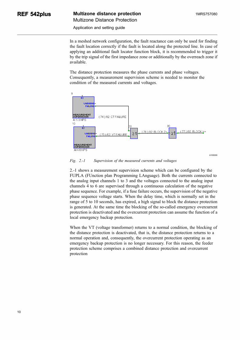
In a meshed network configuration, the fault reactance can only be used for findingthe fault location correctly if the fault is located along the protected line. In case ofapplying an additional fault locator function block, it is recommended to trigger itby the trip signal of the first impedance zone or additionally by the overreach zone ifavailable.
The distance protection measures the phase currents and phase voltages.Consequently, a measurement supervision scheme is needed to monitor thecondition of the measured currents and voltages.
A100000
Fig. 2.-1 Supervision of the measured currents and voltages
2.-1 shows a measurement supervision scheme which can be configured by theFUPLA (FUnction plan Programming LAnguage). Both the currents connected tothe analog input channels 1 to 3 and the voltages connected to the analog inputchannels 4 to 6 are supervised through a continuous calculation of the negativephase sequence. For example, if a fuse failure occurs, the supervision of the negativephase sequence voltage starts. When the delay time, which is normally set in therange of 5 to 10 seconds, has expired, a high signal to block the distance protectionis generated. At the same time the blocking of the so-called emergency overcurrentprotection is deactivated and the overcurrent protection can assume the function of alocal emergency backup protection.
When the VT (voltage transformer) returns to a normal condition, the blocking ofthe distance protection is deactivated, that is, the distance protection returns to anormal operation and, consequently, the overcurrent protection operating as anemergency backup protection is no longer necessary. For this reason, the feederprotection scheme comprises a combined distance protection and overcurrentprotection
10
REF 542plusREF 542plus Multizone distance protectionMultizone Distance Protection
Application and setting guide
1MRS757080
11
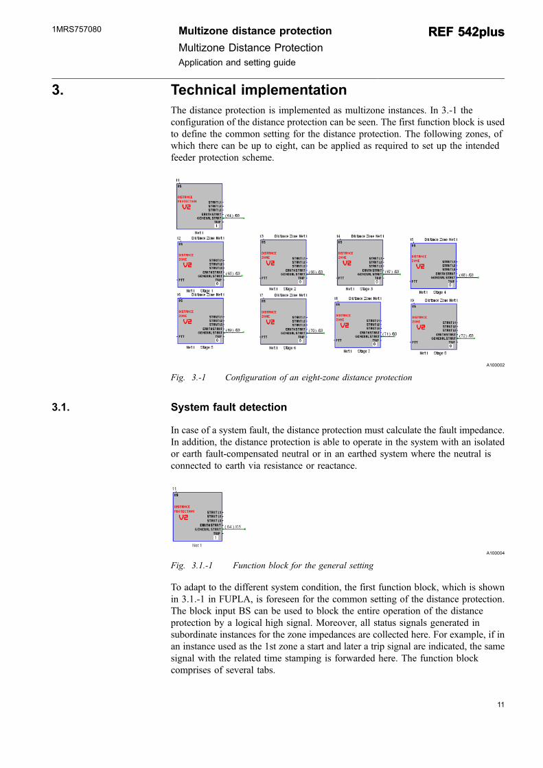
3. Technical implementationThe distance protection is implemented as multizone instances. In 3.-1 theconfiguration of the distance protection can be seen. The first function block is usedto define the common setting for the distance protection. The following zones, ofwhich there can be up to eight, can be applied as required to set up the intendedfeeder protection scheme.
A100002
Fig. 3.-1 Configuration of an eight-zone distance protection
3.1. System fault detection
In case of a system fault, the distance protection must calculate the fault impedance.In addition, the distance protection is able to operate in the system with an isolatedor earth fault-compensated neutral or in an earthed system where the neutral isconnected to earth via resistance or reactance.
A100004
Fig. 3.1.-1 Function block for the general setting
To adapt to the different system condition, the first function block, which is shownin 3.1.-1 in FUPLA, is foreseen for the common setting of the distance protection.The block input BS can be used to block the entire operation of the distanceprotection by a logical high signal. Moreover, all status signals generated insubordinate instances for the zone impedances are collected here. For example, if inan instance used as the 1st zone a start and later a trip signal are indicated, the samesignal with the related time stamping is forwarded here. The function blockcomprises of several tabs.
Multizone distance protection
Multizone Distance ProtectionApplication and setting guide
REF 542plusREF 542plus1MRS757080
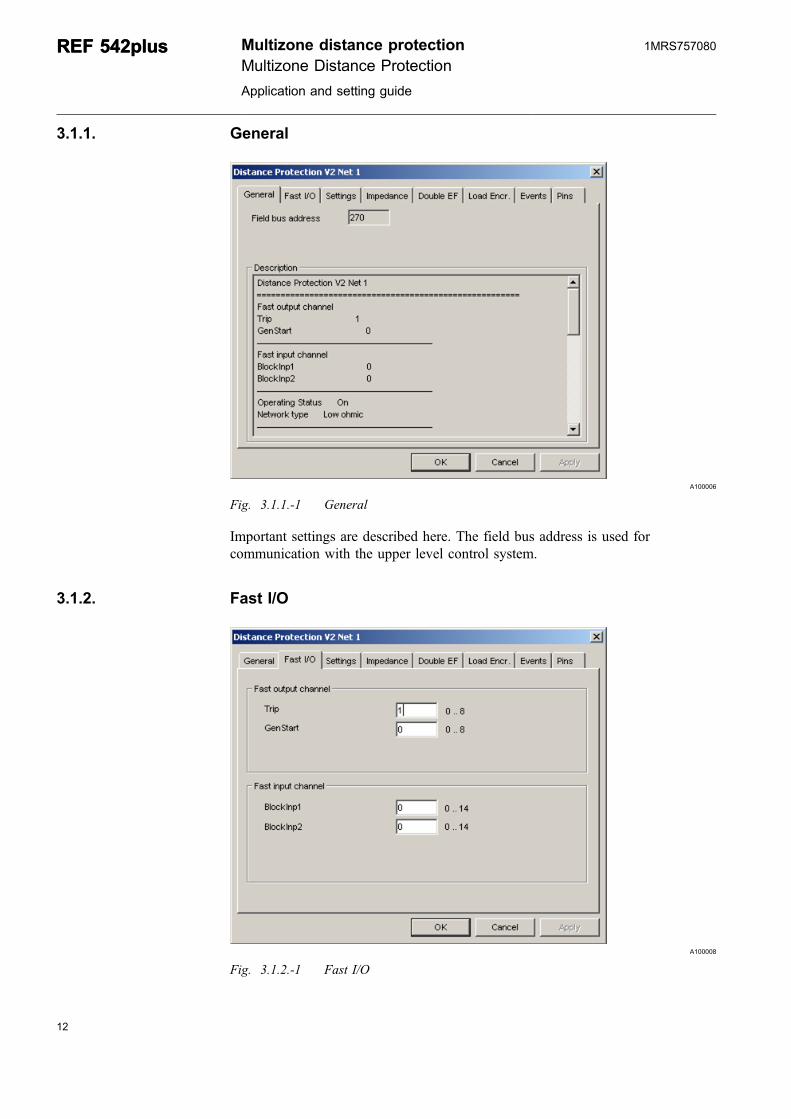
3.1.1. General
A100006
Fig. 3.1.1.-1 General
Important settings are described here. The field bus address is used forcommunication with the upper level control system.
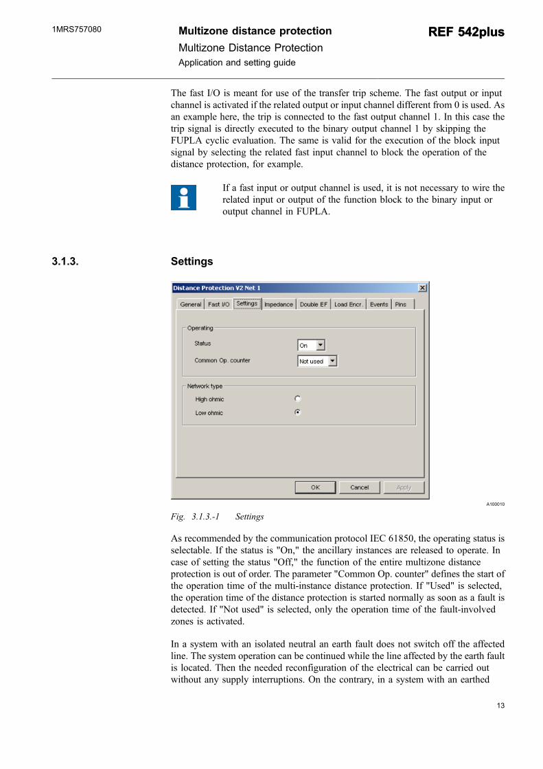
3.1.2. Fast I/O
A100008
Fig. 3.1.2.-1 Fast I/O
12
REF 542plusREF 542plus Multizone distance protectionMultizone Distance Protection
Application and setting guide
1MRS757080
13
The fast I/O is meant for use of the transfer trip scheme. The fast output or inputchannel is activated if the related output or input channel different from 0 is used. Asan example here, the trip is connected to the fast output channel 1. In this case thetrip signal is directly executed to the binary output channel 1 by skipping theFUPLA cyclic evaluation. The same is valid for the execution of the block inputsignal by selecting the related fast input channel to block the operation of thedistance protection, for example.
If a fast input or output channel is used, it is not necessary to wire therelated input or output of the function block to the binary input oroutput channel in FUPLA.
3.1.3. Settings
A100010
Fig. 3.1.3.-1 Settings
As recommended by the communication protocol IEC 61850, the operating status isselectable. If the status is "On," the ancillary instances are released to operate. Incase of setting the status "Off," the function of the entire multizone distanceprotection is out of order. The parameter "Common Op. counter" defines the start ofthe operation time of the multi-instance distance protection. If "Used" is selected,the operation time of the distance protection is started normally as soon as a fault isdetected. If "Not used" is selected, only the operation time of the fault-involvedzones is activated.
In a system with an isolated neutral an earth fault does not switch off the affectedline. The system operation can be continued while the line affected by the earth faultis located. Then the needed reconfiguration of the electrical can be carried outwithout any supply interruptions. On the contrary, in a system with an earthed
Multizone distance protection
Multizone Distance ProtectionApplication and setting guide
REF 542plusREF 542plus1MRS757080
neutral a line affected by an earth fault must be switched off. As the distanceprotection operates both in a system with an isolated or an earthed neutral, thecorrect network type must therefore be selected by the related option button.
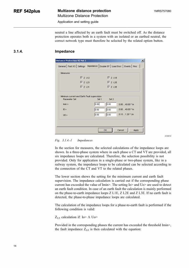
3.1.4. Impedance
A100012
Fig. 3.1.4.-1 Impedances
In the section for measures, the selected calculations of the impedance loops areshown. In a three-phase system where in each phase a CT and VT are provided, allsix impedance loops are calculated. Therefore, the selection possibility is notprovided. Only for application in a single-phase or two-phase system, like in arailway system, the impedance loops to be calculated can be selected according tothe connection of the CT and VT to the related phases.
The lower section shows the setting for the minimum current and earth faultsupervision. The impedance calculation is carried out if the corresponding phasecurrent has exceeded the value of Imin>. The setting Io> and Uo> are used to detectan earth fault condition. In case of an earth fault the calculation is mainly performedon the phase-to-earth impedance loops Z L1E, Z L2E and Z L3E. If no earth fault isdetected, the phase-to-phase impedance loops are calculated.
The calculation of the impedance loops for a phase-to-earth fault is performed if thefollowing condition is valid:
ZLE calculation if: Io> Λ Uo>
Provided in the corresponding phases the current has exceeded the threshold Imin>,the fault impedance ZLE is then calculated with the equation:
14
REF 542plusREF 542plus Multizone distance protectionMultizone Distance Protection
Application and setting guide
1MRS757080
15
ZU
I K ILELE
L E=
+ ⋅ (1)
Whether IE is the neutral or the residual current can be estimated with the equation:
I I I IE L L L= + +1 2 3 (2)
K is the so-called earth factor according to the equation:
KZZ
Z ZZL
L
L= ⋅ −
⎛
⎝⎜
⎞
⎠⎟ = ⋅
−⎛
⎝⎜
⎞
⎠⎟
13
1 13
0 0 (3)
The calculation of the impedance loops for phase-to-phase fault is performed if theabove condition for earth fault is not valid. The fault impedance ZLL is performed inthe phases where the phase current has exceeded the threshold Imin>. Theimpedance is calculated with the equation:
ZUILL
LL
LL= (4)
Therefore, ULL is the line voltage and ILL the so-called line current. The calculationscheme of the line voltage or line current is the same. For example, the line currentI12 can be calculated with the equation:
I I IL L12 1 2= − (5)
The same scheme is also used for calculating the line voltages.
Multizone distance protection
Multizone Distance ProtectionApplication and setting guide
REF 542plusREF 542plus1MRS757080
3.1.5. Double earth fault
A100014
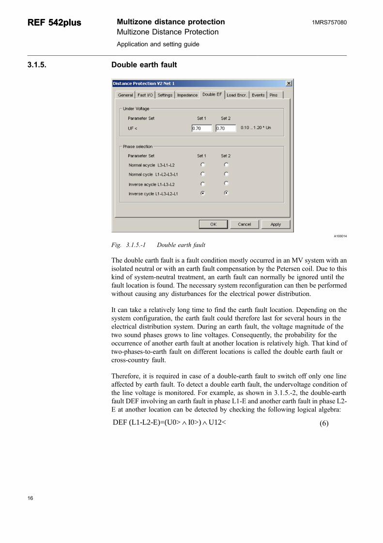
Fig. 3.1.5.-1 Double earth fault
The double earth fault is a fault condition mostly occurred in an MV system with anisolated neutral or with an earth fault compensation by the Petersen coil. Due to thiskind of system-neutral treatment, an earth fault can normally be ignored until thefault location is found. The necessary system reconfiguration can then be performedwithout causing any disturbances for the electrical power distribution.
It can take a relatively long time to find the earth fault location. Depending on thesystem configuration, the earth fault could therefore last for several hours in theelectrical distribution system. During an earth fault, the voltage magnitude of thetwo sound phases grows to line voltages. Consequently, the probability for theoccurrence of another earth fault at another location is relatively high. That kind oftwo-phases-to-earth fault on different locations is called the double earth fault orcross-country fault.
Therefore, it is required in case of a double-earth fault to switch off only one lineaffected by earth fault. To detect a double earth fault, the undervoltage condition ofthe line voltage is monitored. For example, as shown in 3.1.5.-2, the double-earthfault DEF involving an earth fault in phase L1-E and another earth fault in phase L2-E at another location can be detected by checking the following logical algebra:
DEF (L1-L2-E)=(U0> I0>) U12<∧ ∧ (6)
16
REF 542plusREF 542plus Multizone distance protectionMultizone Distance Protection
Application and setting guide
1MRS757080
17
A100016
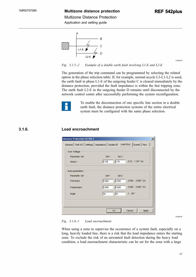
Fig. 3.1.5.-2 Example of a double earth fault involving L1-E and L2-E
The generation of the trip command can be programmed by selecting the relatedoption in the phase selection table. If, for example, normal acycle L3-L1-L2 is used,the earth fault in phase L1-E of the outgoing feeder C is cleared immediately by thedistance protection, provided the fault impedance is within the fast tripping zone.The earth fault L2-E in the outgoing feeder D remains until disconnected by thenetwork control center after successfully performing the system reconfiguration.
To enable the disconnection of one specific line section in a doubleearth fault, the distance protection systems of the entire electricalsystem must be configured with the same phase selection.
3.1.6. Load encroachment
A100018
Fig. 3.1.6.-1 Load encroachment
When using a zone to supervise the occurrence of a system fault, especially on along, heavily loaded line, there is a risk that the load impedance enters the startingzone. To exclude the risk of an unwanted fault detection during the heavy loadcondition, a load encroachment characteristic can be set for the zone with a large
Multizone distance protection
Multizone Distance ProtectionApplication and setting guide
REF 542plusREF 542plus1MRS757080
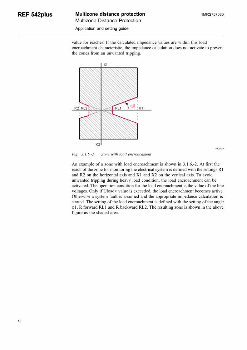
value for reaches. If the calculated impedance values are within this loadencroachment characteristic, the impedance calculation does not activate to preventthe zones from an unwanted tripping.
A100020
Fig. 3.1.6.-2 Zone with load encroachment
An example of a zone with load encroachment is shown in 3.1.6.-2. At first thereach of the zone for monitoring the electrical system is defined with the settings R1and R2 on the horizontal axis and X1 and X2 on the vertical axis. To avoidunwanted tripping during heavy load condition, the load encroachment can beactivated. The operation condition for the load encroachment is the value of the linevoltages. Only if Uload> value is exceeded, the load encroachment becomes active.Otherwise a system fault is assumed and the appropriate impedance calculation isstarted. The setting of the load encroachment is defined with the setting of the angleφ1, R forward RL1 and R backward RL2. The resulting zone is shown in the abovefigure as the shaded area.
18
REF 542plusREF 542plus Multizone distance protectionMultizone Distance Protection
Application and setting guide
1MRS757080
19
3.1.7. Events
A100022
Fig. 3.1.7.-1 Events
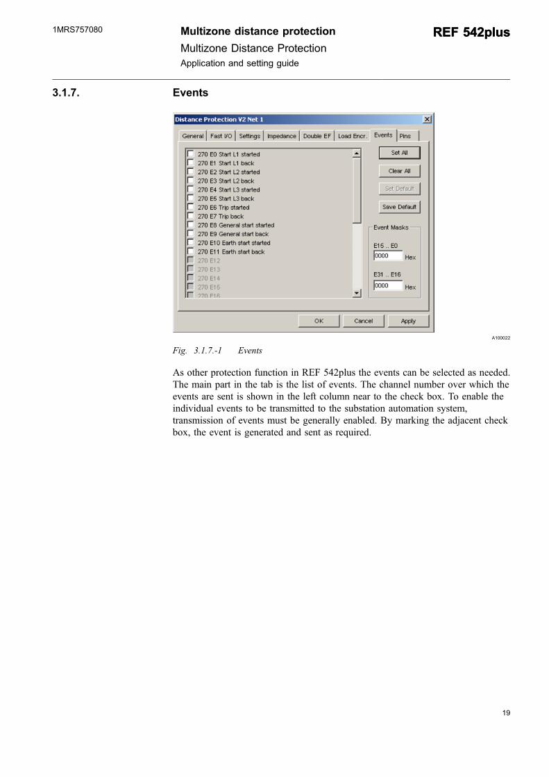
As other protection function in REF 542plus the events can be selected as needed.The main part in the tab is the list of events. The channel number over which theevents are sent is shown in the left column near to the check box. To enable theindividual events to be transmitted to the substation automation system,transmission of events must be generally enabled. By marking the adjacent checkbox, the event is generated and sent as required.
Multizone distance protection
Multizone Distance ProtectionApplication and setting guide
REF 542plusREF 542plus1MRS757080
3.1.8. Pins
A100024
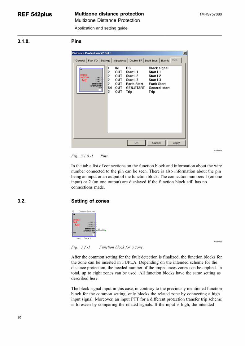
Fig. 3.1.8.-1 Pins
In the tab a list of connections on the function block and information about the wirenumber connected to the pin can be seen. There is also information about the pinbeing an input or an output of the function block. The connection numbers 1 (on oneinput) or 2 (on one output) are displayed if the function block still has noconnections made.
3.2. Setting of zones
A100026
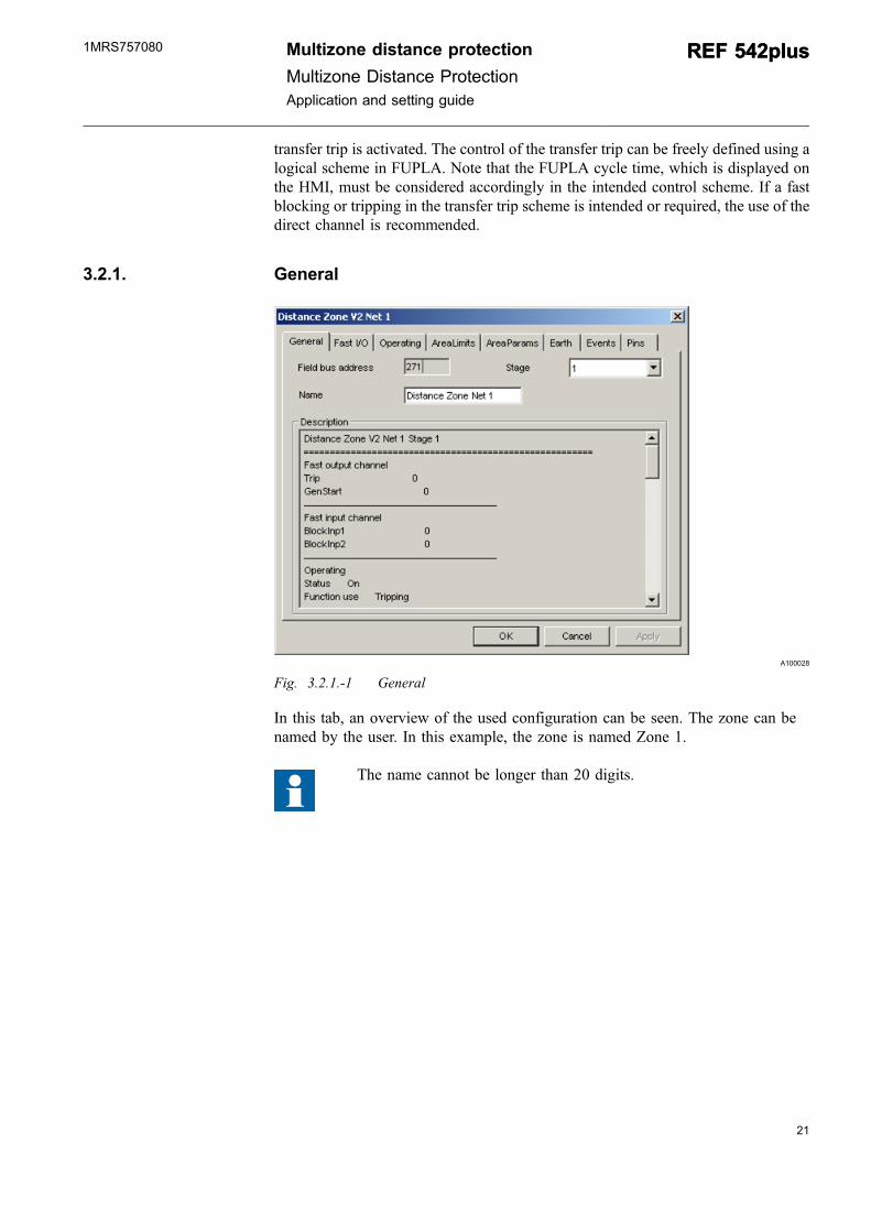
Fig. 3.2.-1 Function block for a zone
After the common setting for the fault detection is finalized, the function blocks forthe zone can be inserted in FUPLA. Depending on the intended scheme for thedistance protection, the needed number of the impedances zones can be applied. Intotal, up to eight zones can be used. All function blocks have the same setting asdescribed here.
The block signal input in this case, in contrary to the previously mentioned functionblock for the common setting, only blocks the related zone by connecting a highinput signal. Moreover, an input PTT for a different protection transfer trip schemeis foreseen by comparing the related signals. If the input is high, the intended
20
REF 542plusREF 542plus Multizone distance protectionMultizone Distance Protection
Application and setting guide
1MRS757080
21
transfer trip is activated. The control of the transfer trip can be freely defined using alogical scheme in FUPLA. Note that the FUPLA cycle time, which is displayed onthe HMI, must be considered accordingly in the intended control scheme. If a fastblocking or tripping in the transfer trip scheme is intended or required, the use of thedirect channel is recommended.
3.2.1. General
A100028
Fig. 3.2.1.-1 General
In this tab, an overview of the used configuration can be seen. The zone can benamed by the user. In this example, the zone is named Zone 1.
The name cannot be longer than 20 digits.
Multizone distance protection
Multizone Distance ProtectionApplication and setting guide
REF 542plusREF 542plus1MRS757080
3.2.2. Fast I/O
A100030
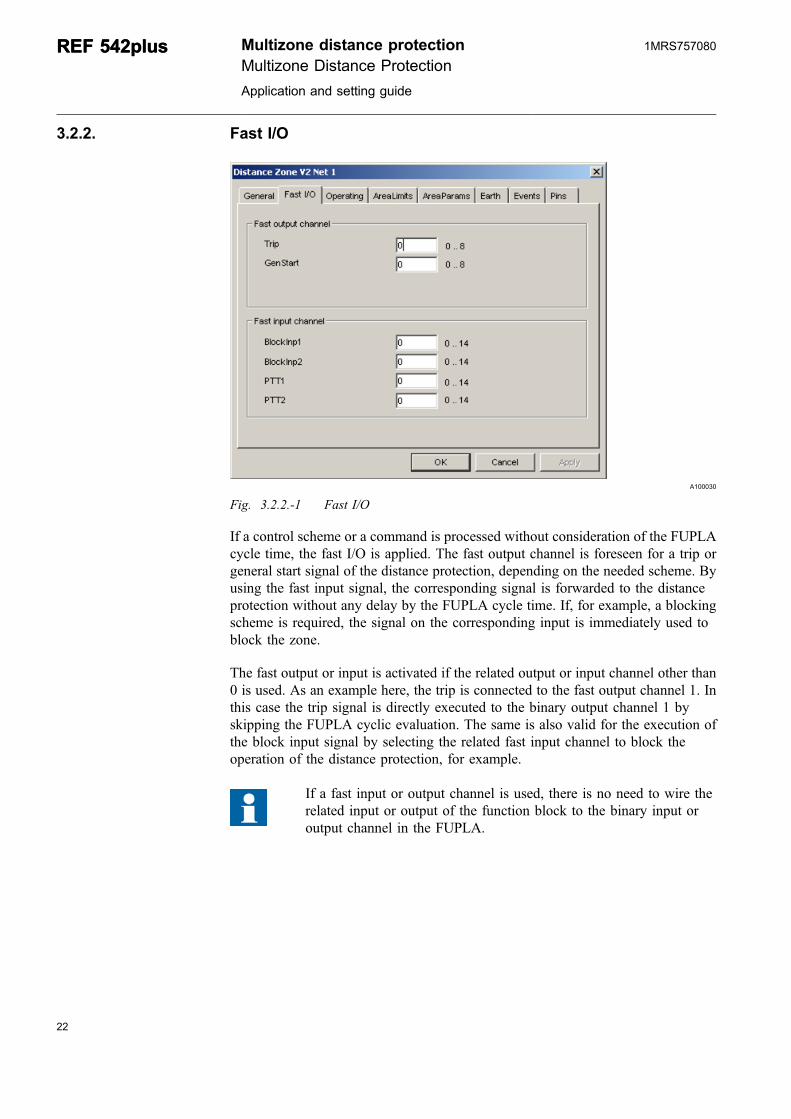
Fig. 3.2.2.-1 Fast I/O
If a control scheme or a command is processed without consideration of the FUPLAcycle time, the fast I/O is applied. The fast output channel is foreseen for a trip orgeneral start signal of the distance protection, depending on the needed scheme. Byusing the fast input signal, the corresponding signal is forwarded to the distanceprotection without any delay by the FUPLA cycle time. If, for example, a blockingscheme is required, the signal on the corresponding input is immediately used toblock the zone.
The fast output or input is activated if the related output or input channel other than0 is used. As an example here, the trip is connected to the fast output channel 1. Inthis case the trip signal is directly executed to the binary output channel 1 byskipping the FUPLA cyclic evaluation. The same is also valid for the execution ofthe block input signal by selecting the related fast input channel to block theoperation of the distance protection, for example.
If a fast input or output channel is used, there is no need to wire therelated input or output of the function block to the binary input oroutput channel in the FUPLA.
22
REF 542plusREF 542plus Multizone distance protectionMultizone Distance Protection
Application and setting guide
1MRS757080
23
3.2.3. Operating
A100032
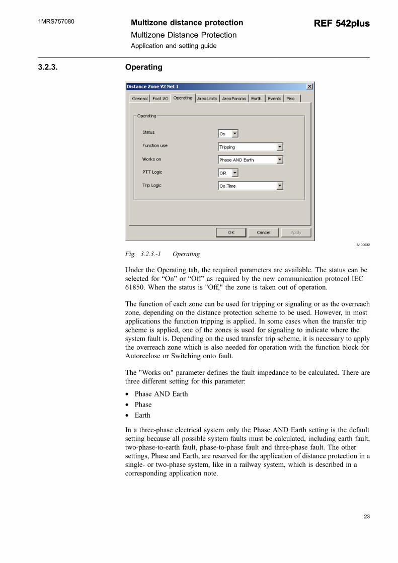
Fig. 3.2.3.-1 Operating
Under the Operating tab, the required parameters are available. The status can beselected for “On” or “Off” as required by the new communication protocol IEC61850. When the status is "Off," the zone is taken out of operation.
The function of each zone can be used for tripping or signaling or as the overreachzone, depending on the distance protection scheme to be used. However, in mostapplications the function tripping is applied. In some cases when the transfer tripscheme is applied, one of the zones is used for signaling to indicate where thesystem fault is. Depending on the used transfer trip scheme, it is necessary to applythe overreach zone which is also needed for operation with the function block forAutoreclose or Switching onto fault.
The "Works on" parameter defines the fault impedance to be calculated. There arethree different setting for this parameter:
* Phase AND Earth* Phase* Earth
In a three-phase electrical system only the Phase AND Earth setting is the defaultsetting because all possible system faults must be calculated, including earth fault,two-phase-to-earth fault, phase-to-phase fault and three-phase fault. The othersettings, Phase and Earth, are reserved for the application of distance protection in asingle- or two-phase system, like in a railway system, which is described in acorresponding application note.
Multizone distance protection
Multizone Distance ProtectionApplication and setting guide
REF 542plusREF 542plus1MRS757080
The PTT Logic parameter is meant to improve the selectivity of the distanceprotection by transfer trip scheme. Therefore two setting, "OR" and "AND," areprovided.
Trip Logic must be defined. There are four settings available.
* Operation Time* Operation Time AND PTT* Operation Time OR PTT* PTT
3.2.4. Area limits
A100034
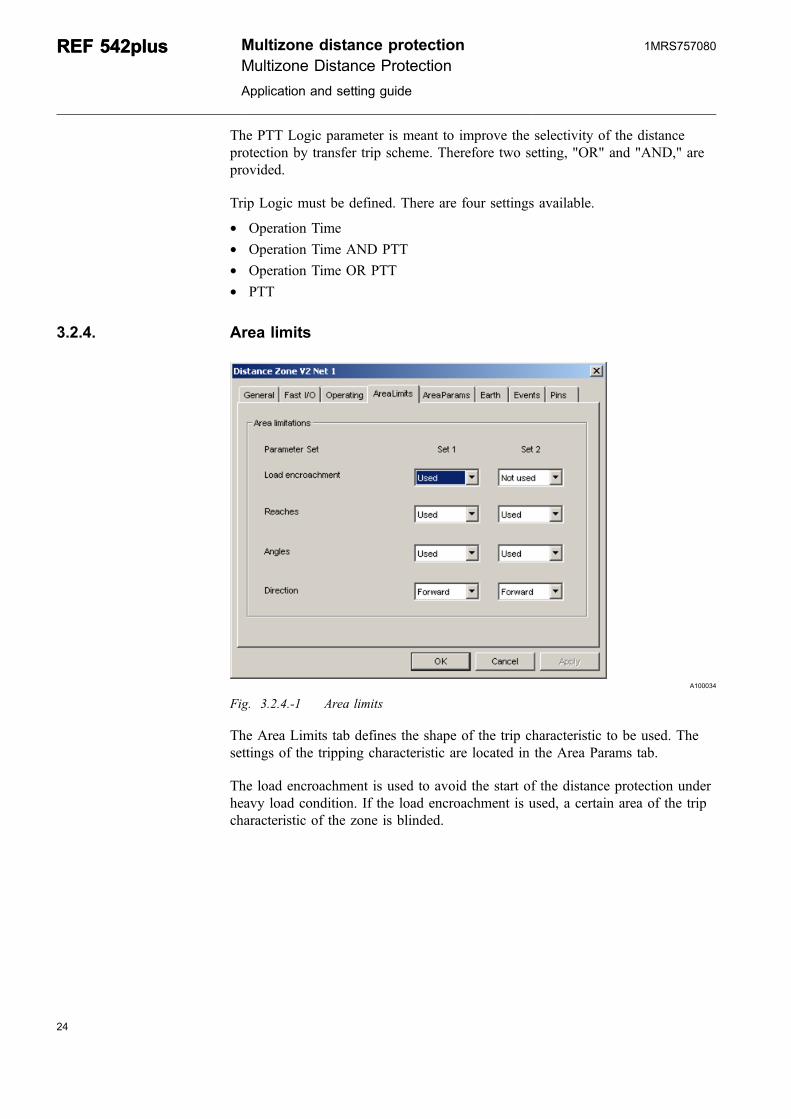
Fig. 3.2.4.-1 Area limits
The Area Limits tab defines the shape of the trip characteristic to be used. Thesettings of the tripping characteristic are located in the Area Params tab.
The load encroachment is used to avoid the start of the distance protection underheavy load condition. If the load encroachment is used, a certain area of the tripcharacteristic of the zone is blinded.
24
REF 542plusREF 542plus Multizone distance protectionMultizone Distance Protection
Application and setting guide
1MRS757080
25
A100036
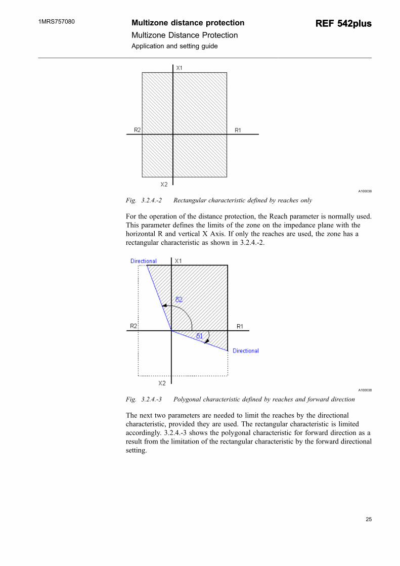
Fig. 3.2.4.-2 Rectangular characteristic defined by reaches only
For the operation of the distance protection, the Reach parameter is normally used.This parameter defines the limits of the zone on the impedance plane with thehorizontal R and vertical X Axis. If only the reaches are used, the zone has arectangular characteristic as shown in 3.2.4.-2.
A100038
Fig. 3.2.4.-3 Polygonal characteristic defined by reaches and forward direction
The next two parameters are needed to limit the reaches by the directionalcharacteristic, provided they are used. The rectangular characteristic is limitedaccordingly. 3.2.4.-3 shows the polygonal characteristic for forward direction as aresult from the limitation of the rectangular characteristic by the forward directionalsetting.
Multizone distance protection
Multizone Distance ProtectionApplication and setting guide
REF 542plusREF 542plus1MRS757080
A100040
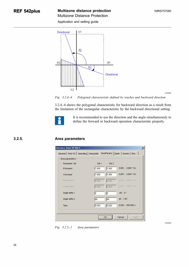
Fig. 3.2.4.-4 Polygonal characteristic defined by reaches and backward direction
3.2.4.-4 shows the polygonal characteristic for backward direction as a result fromthe limitation of the rectangular characteristic by the backward directional setting.
It is recommended to use the direction and the angle simultaneously todefine the forward or backward operation characteristic properly.
3.2.5. Area parameters
A100042
Fig. 3.2.5.-1 Area parameters
26
REF 542plusREF 542plus Multizone distance protectionMultizone Distance Protection
Application and setting guide
1MRS757080
27
The AreaParams tab describes the range of the setting value. The setting values ofthe reaches for the zones, Rforward, Xforward, Rbackward and Xbackward, arereferred to as the rated impedance value Zn, which is defined by the rated value ofthe voltage transformer and the current transformers. If, for example, in the MVsystem a 10 Ω reactance is to be reached by a zone where the rated value for the VTis 20 kV and the CT 400 A, the setting value to be set is as follows:
XsetZn kV
A
= 1020400
Ω(7)
where Xset = 0.2 Zn.
The angles delta 1 and delta 2 are used to limit the rectangular operationcharacteristic of the zones by the directional setting.
The operation time can be set separately in each zone. As soon as a system fault isdetected, the operation time of all the activated zones in FUPLA is startedsimultaneously.
3.2.6. Earth
A100044
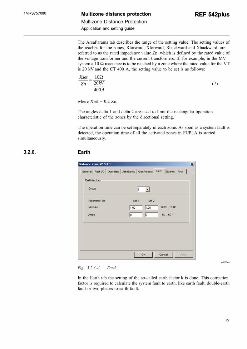
Fig. 3.2.6.-1 Earth
In the Earth tab the setting of the so-called earth factor k is done. This correctionfactor is required to calculate the system fault to earth, like earth fault, double-earthfault or two-phases-to-earth fault.
Multizone distance protection
Multizone Distance ProtectionApplication and setting guide
REF 542plusREF 542plus1MRS757080
Four earth factor group setting are provided in total. In each zone thecorrect earth factor group setting is defined accordingly. For example,zone Z1 uses the setting of group 1 and zone Z2 uses the setting ofgroup 2.
3.2.7. Events
A100046
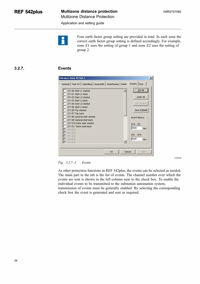
Fig. 3.2.7.-1 Events
As other protection functions in REF 542plus, the events can be selected as needed.The main part in the tab is the list of events. The channel number over which theevents are sent is shown in the left column near to the check box. To enable theindividual events to be transmitted to the substation automation system,transmission of events must be generally enabled. By selecting the correspondingcheck box the event is generated and sent as required.
28
REF 542plusREF 542plus Multizone distance protectionMultizone Distance Protection
Application and setting guide
1MRS757080
29
3.2.8. Pins
A100048
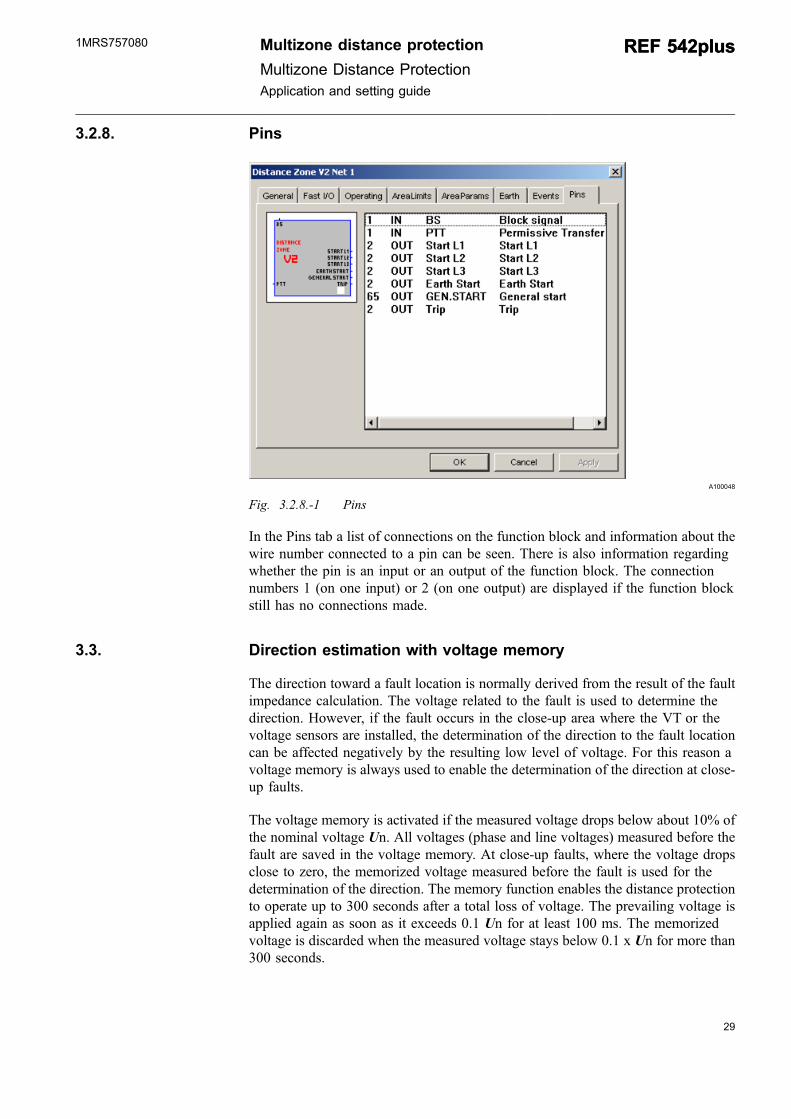
Fig. 3.2.8.-1 Pins
In the Pins tab a list of connections on the function block and information about thewire number connected to a pin can be seen. There is also information regardingwhether the pin is an input or an output of the function block. The connectionnumbers 1 (on one input) or 2 (on one output) are displayed if the function blockstill has no connections made.
3.3. Direction estimation with voltage memory
The direction toward a fault location is normally derived from the result of the faultimpedance calculation. The voltage related to the fault is used to determine thedirection. However, if the fault occurs in the close-up area where the VT or thevoltage sensors are installed, the determination of the direction to the fault locationcan be affected negatively by the resulting low level of voltage. For this reason avoltage memory is always used to enable the determination of the direction at close-up faults.
The voltage memory is activated if the measured voltage drops below about 10% ofthe nominal voltage Un. All voltages (phase and line voltages) measured before thefault are saved in the voltage memory. At close-up faults, where the voltage dropsclose to zero, the memorized voltage measured before the fault is used for thedetermination of the direction. The memory function enables the distance protectionto operate up to 300 seconds after a total loss of voltage. The prevailing voltage isapplied again as soon as it exceeds 0.1 Un for at least 100 ms. The memorizedvoltage is discarded when the measured voltage stays below 0.1 x Un for more than300 seconds.
Multizone distance protection
Multizone Distance ProtectionApplication and setting guide
REF 542plusREF 542plus1MRS757080
When a fault occurs, a phase displacement with an angle ofapproximately ±30° between the corresponding phase voltages beforeand after the fault occurrence can take place. This can happen, forexample, when the fault situation develops into a double-earth fault.This fact should be taken into account when the directionalcharacteristic is to be set too close to the tripping area of the distanceprotection.
The tripping characteristic should be set as follows to obtain a permanent optimaldetermination of the direction:
In the 2nd quadrant:
* δ2=90º+30º=120º
and in the 4th quadrant:
* δ1=0º-30º=-30º
If the voltage memory is not available, for example during theenergizing of a line where the voltage transformer is located at the lineside, the directional estimation is due to electromagnetic disturbancesnot reliable. Therefore, if the related voltage measurement quantity islow, for example in the range of 1% to 2% Un, a trip is forced to ensurethat the fault on the energized line is disconnected. For this borderlinecase, an unselective trip is tolerated.
3.4. Switching onto fault
To cover all the possible faults during the system operation, it is recommended toapply the switching onto fault SOTF protection in addition to the distanceprotection. SOTF is designed as an independent function block and used to protectthe line during the closing of the circuit breaker. If a fault on the protected line isdetected, the switching onto fault protection trips the circuit breaker according to theoperation time of the corresponding protection.
If the switching onto fault protection is in operation together with the distanceprotection V2, it is recommended to use its overreach zone as shown in 3.4.-1.
30
REF 542plusREF 542plus Multizone distance protectionMultizone Distance Protection
Application and setting guide
1MRS757080
31
A100546
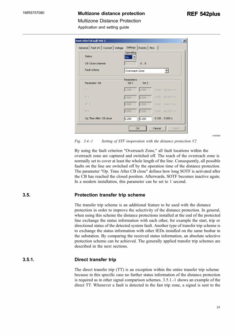
Fig. 3.4.-1 Setting of STF inoperation with the distance protection V2
By using the fault criterion "Overreach Zone," all fault locations within theoverreach zone are captured and switched off. The reach of the overreach zone isnormally set to cover at least the whole length of the line. Consequently, all possiblefaults on the line are switched off by the operation time of the distance protection.The parameter "Op. Time After CB close" defines how long SOTF is activated afterthe CB has reached the closed position. Afterwards, SOTF becomes inactive again.In a modern installation, this parameter can be set to 1 second.
3.5. Protection transfer trip scheme
The transfer trip scheme is an additional feature to be used with the distanceprotection in order to improve the selectivity of the distance protection. In general,when using this scheme the distance protections installed at the end of the protectedline exchange the status information with each other, for example the start, trip ordirectional status of the detected system fault. Another type of transfer trip scheme isto exchange the status information with other IEDs installed on the same busbar inthe substation. By comparing the received status information, an absolute selectiveprotection scheme can be achieved. The generally applied transfer trip schemes aredescribed in the next sections.
3.5.1. Direct transfer trip
The direct transfer trip (TT) is an exception within the entire transfer trip schemebecause in this specific case no further status information of the distance protectionis required as in other signal comparison schemes. 3.5.1.-1 shows an example of thedirect TT. Whenever a fault is detected in the fast trip zone, a signal is sent to the
Multizone distance protection
Multizone Distance ProtectionApplication and setting guide
REF 542plusREF 542plus1MRS757080
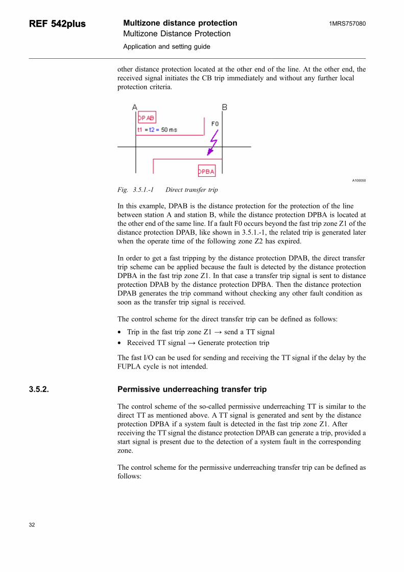
other distance protection located at the other end of the line. At the other end, thereceived signal initiates the CB trip immediately and without any further localprotection criteria.
A100050
Fig. 3.5.1.-1 Direct transfer trip
In this example, DPAB is the distance protection for the protection of the linebetween station A and station B, while the distance protection DPBA is located atthe other end of the same line. If a fault F0 occurs beyond the fast trip zone Z1 of thedistance protection DPAB, like shown in 3.5.1.-1, the related trip is generated laterwhen the operate time of the following zone Z2 has expired.
In order to get a fast tripping by the distance protection DPAB, the direct transfertrip scheme can be applied because the fault is detected by the distance protectionDPBA in the fast trip zone Z1. In that case a transfer trip signal is sent to distanceprotection DPAB by the distance protection DPBA. Then the distance protectionDPAB generates the trip command without checking any other fault condition assoon as the transfer trip signal is received.
The control scheme for the direct transfer trip can be defined as follows:
* Trip in the fast trip zone Z1 → send a TT signal* Received TT signal → Generate protection trip
The fast I/O can be used for sending and receiving the TT signal if the delay by theFUPLA cycle is not intended.
3.5.2. Permissive underreaching transfer trip
The control scheme of the so-called permissive underreaching TT is similar to thedirect TT as mentioned above. A TT signal is generated and sent by the distanceprotection DPBA if a system fault is detected in the fast trip zone Z1. Afterreceiving the TT signal the distance protection DPAB can generate a trip, provided astart signal is present due to the detection of a system fault in the correspondingzone.
The control scheme for the permissive underreaching transfer trip can be defined asfollows:
32
REF 542plusREF 542plus Multizone distance protectionMultizone Distance Protection
Application and setting guide
1MRS757080
33
* Trip in the fast trip zone Z1 → Send a TT signal* Received TT signal → Generate a protection trip command if the general start
signal is available
It is recommended to use the common operation counter.
The fast I/O can be used for sending and receiving the TT signal if a delay by theFUPLA cycle is not intended.
3.5.3. Zone acceleration
The next control scheme is the so-called zone acceleration scheme. Zone 2 is anoverreach zone Zov and is normally not in use. As soon as the distance protectionDPBA detects a fault in the fast trip zone Z1, a TT signal is sent to the distanceprotection DPAB at the other end of the line. When the signal is received by thedistance protection DPAB, the overreach zone Zov is activated, which againgenerates the trip within the related operation time.
The control scheme for the zone acceleration scheme can be defined as following:
* Trip in fast trip zone Z1 → Send a TT signal* Received TT signal → Release overreach zone Zov for operation
The fast I/O can be used for sending and receiving the TT signal if a delay by theFUPLA cycle is not intended.
3.5.4. Permissive overreaching transfer trip
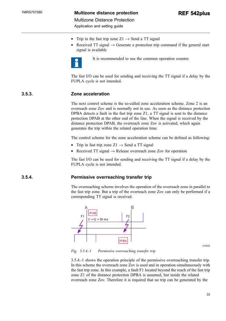
The overreaching scheme involves the operation of the overreach zone in parallel tothe fast trip zone. But a trip of the overreach zone Zov can only be performed if acorresponding TT signal is received.
A100052
Fig. 3.5.4.-1 Permissive overreaching transfer trip
3.5.4.-1 shows the operation principle of the permissive overreaching transfer trip.In this scheme the overreach zone Zov is used and in operation simultaneously withthe fast trip zone. In this example, a fault F1 located beyond the reach of the fast tripzone Z1 of the distance protection DPBA is assumed, but inside the relatedoverreach zone Zov. Therefore it is required that no trip can be generated by the
Multizone distance protection
Multizone Distance ProtectionApplication and setting guide
REF 542plusREF 542plus1MRS757080
distance protection DPBA because the fault is not detected by the distanceprotection DPAB. Only for the fault F2 the generation of the trip by the distanceprotection DPAB is possible because now the distance protection DPBA detects afault inside the fast trip zone Z1 and also inside the overreach zone Zov.Consequently, a signal can be sent by the distance protection DPBA to release thetrip of the overreach zone of DPAB.
A100054
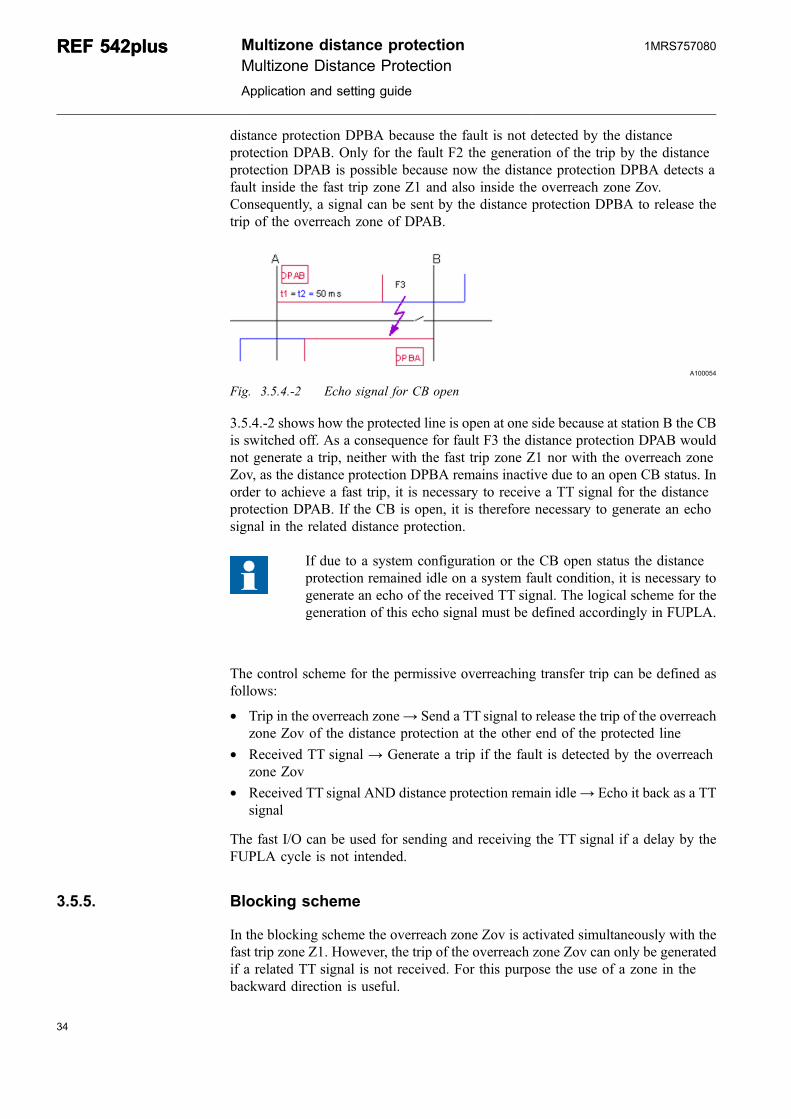
Fig. 3.5.4.-2 Echo signal for CB open
3.5.4.-2 shows how the protected line is open at one side because at station B the CBis switched off. As a consequence for fault F3 the distance protection DPAB wouldnot generate a trip, neither with the fast trip zone Z1 nor with the overreach zoneZov, as the distance protection DPBA remains inactive due to an open CB status. Inorder to achieve a fast trip, it is necessary to receive a TT signal for the distanceprotection DPAB. If the CB is open, it is therefore necessary to generate an echosignal in the related distance protection.
If due to a system configuration or the CB open status the distanceprotection remained idle on a system fault condition, it is necessary togenerate an echo of the received TT signal. The logical scheme for thegeneration of this echo signal must be defined accordingly in FUPLA.
The control scheme for the permissive overreaching transfer trip can be defined asfollows:
* Trip in the overreach zone→ Send a TT signal to release the trip of the overreachzone Zov of the distance protection at the other end of the protected line
* Received TT signal → Generate a trip if the fault is detected by the overreachzone Zov
* Received TT signal AND distance protection remain idle→ Echo it back as a TTsignal
The fast I/O can be used for sending and receiving the TT signal if a delay by theFUPLA cycle is not intended.
3.5.5. Blocking scheme
In the blocking scheme the overreach zone Zov is activated simultaneously with thefast trip zone Z1. However, the trip of the overreach zone Zov can only be generatedif a related TT signal is not received. For this purpose the use of a zone in thebackward direction is useful.
34
REF 542plusREF 542plus Multizone distance protectionMultizone Distance Protection
Application and setting guide
1MRS757080
35
A100056
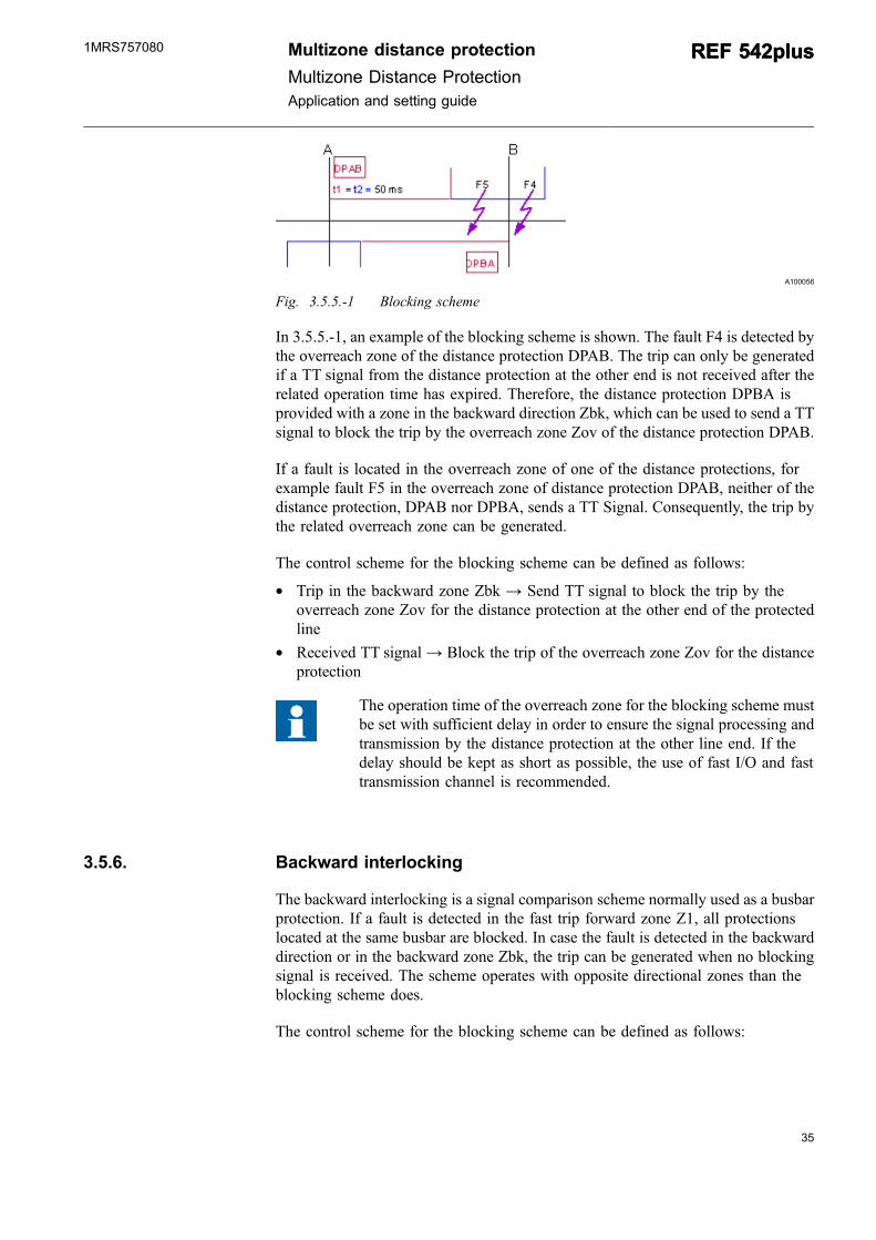
Fig. 3.5.5.-1 Blocking scheme
In 3.5.5.-1, an example of the blocking scheme is shown. The fault F4 is detected bythe overreach zone of the distance protection DPAB. The trip can only be generatedif a TT signal from the distance protection at the other end is not received after therelated operation time has expired. Therefore, the distance protection DPBA isprovided with a zone in the backward direction Zbk, which can be used to send a TTsignal to block the trip by the overreach zone Zov of the distance protection DPAB.
If a fault is located in the overreach zone of one of the distance protections, forexample fault F5 in the overreach zone of distance protection DPAB, neither of thedistance protection, DPAB nor DPBA, sends a TT Signal. Consequently, the trip bythe related overreach zone can be generated.
The control scheme for the blocking scheme can be defined as follows:
* Trip in the backward zone Zbk → Send TT signal to block the trip by theoverreach zone Zov for the distance protection at the other end of the protectedline
* Received TT signal → Block the trip of the overreach zone Zov for the distanceprotection
The operation time of the overreach zone for the blocking scheme mustbe set with sufficient delay in order to ensure the signal processing andtransmission by the distance protection at the other line end. If thedelay should be kept as short as possible, the use of fast I/O and fasttransmission channel is recommended.
3.5.6. Backward interlocking
The backward interlocking is a signal comparison scheme normally used as a busbarprotection. If a fault is detected in the fast trip forward zone Z1, all protectionslocated at the same busbar are blocked. In case the fault is detected in the backwarddirection or in the backward zone Zbk, the trip can be generated when no blockingsignal is received. The scheme operates with opposite directional zones than theblocking scheme does.
The control scheme for the blocking scheme can be defined as follows:
Multizone distance protection
Multizone Distance ProtectionApplication and setting guide
REF 542plusREF 542plus1MRS757080
* Trip in the fast trip zone Z1 → Send TT signal to block the trip of the otherdistance protection located at the same busbar
* Received TT signal → Block the trip of the fast trip zone Z1 of the distanceprotection
The operation time of the overreach zone for the blocking scheme mustbe set with sufficient delay in order to ensure the signal processing inthe distance protection at the other line end. If the delay is to be kept asshort as possible, the use of a fast I/O and fast transmission channel isrecommended.
3.6. Autoreclosure
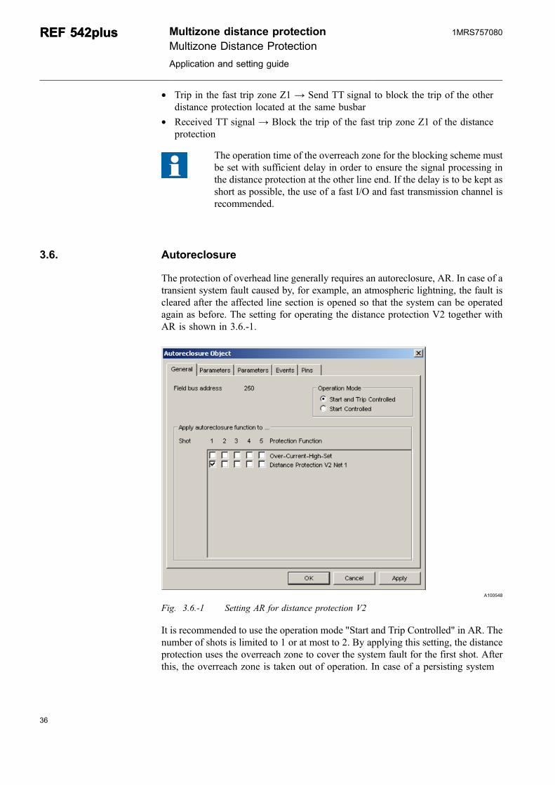
The protection of overhead line generally requires an autoreclosure, AR. In case of atransient system fault caused by, for example, an atmospheric lightning, the fault iscleared after the affected line section is opened so that the system can be operatedagain as before. The setting for operating the distance protection V2 together withAR is shown in 3.6.-1.
A100548
Fig. 3.6.-1 Setting AR for distance protection V2
It is recommended to use the operation mode "Start and Trip Controlled" in AR. Thenumber of shots is limited to 1 or at most to 2. By applying this setting, the distanceprotection uses the overreach zone to cover the system fault for the first shot. Afterthis, the overreach zone is taken out of operation. In case of a persisting system
36
REF 542plusREF 542plus Multizone distance protectionMultizone Distance Protection
Application and setting guide
1MRS757080
37
fault, the trip of the distance protection is carried out by the corresponding zone.Consequently, the fault is cleared according to the time-grading scheme of theprotection coordination.
Multizone distance protection
Multizone Distance ProtectionApplication and setting guide
REF 542plusREF 542plus1MRS757080

38
39
4. Setting exampleThe setting of the distance protection requires detailed knowledge of the MVsystem. To achieve all the data needed, a comprehensive network analysis isrecommended. Any possible power system configuration should be analyzed andthe short-circuit currents for every possible fault condition should be calculated.
At least the maximum short-circuit current is needed for dimensioning the CT andthe minimum short-circuit current, including the minimum residual current, forsetting the threshold of the related zone to detect a system fault. Then the reaches ofthe zones can be derived from the impedance of the protected cable or overheadline.
4.1. Electrical power system
The analysis of the power system is not described in this example. The distanceprotection is assumed to operate under the following system conditions:
* 20 kV MV resonant earthed system* Maximum short-circuit current IMAX 25 kA at busbar in station A* Network time constant for the decaying DC component 45 ms* Maximum load current 400 A* Minimum short-circuit current IMIN = 200 A* Minimum residua current IRES = 100 A
Measurement transformer ratings:
* CT: 300 A/1 A* VT: 20 kV/100 V
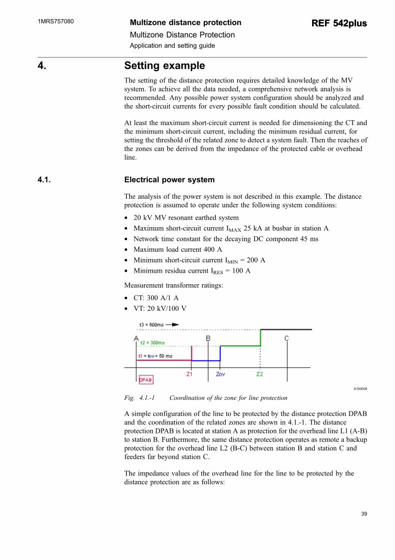
A100058
Fig. 4.1.-1 Coordination of the zone for line protection
A simple configuration of the line to be protected by the distance protection DPABand the coordination of the related zones are shown in 4.1.-1. The distanceprotection DPAB is located at station A as protection for the overhead line L1 (A-B)to station B. Furthermore, the same distance protection operates as remote a backupprotection for the overhead line L2 (B-C) between station B and station C andfeeders far beyond station C.
The impedance values of the overhead line for the line to be protected by thedistance protection are as follows:
Multizone distance protection
Multizone Distance ProtectionApplication and setting guide
REF 542plusREF 542plus1MRS757080
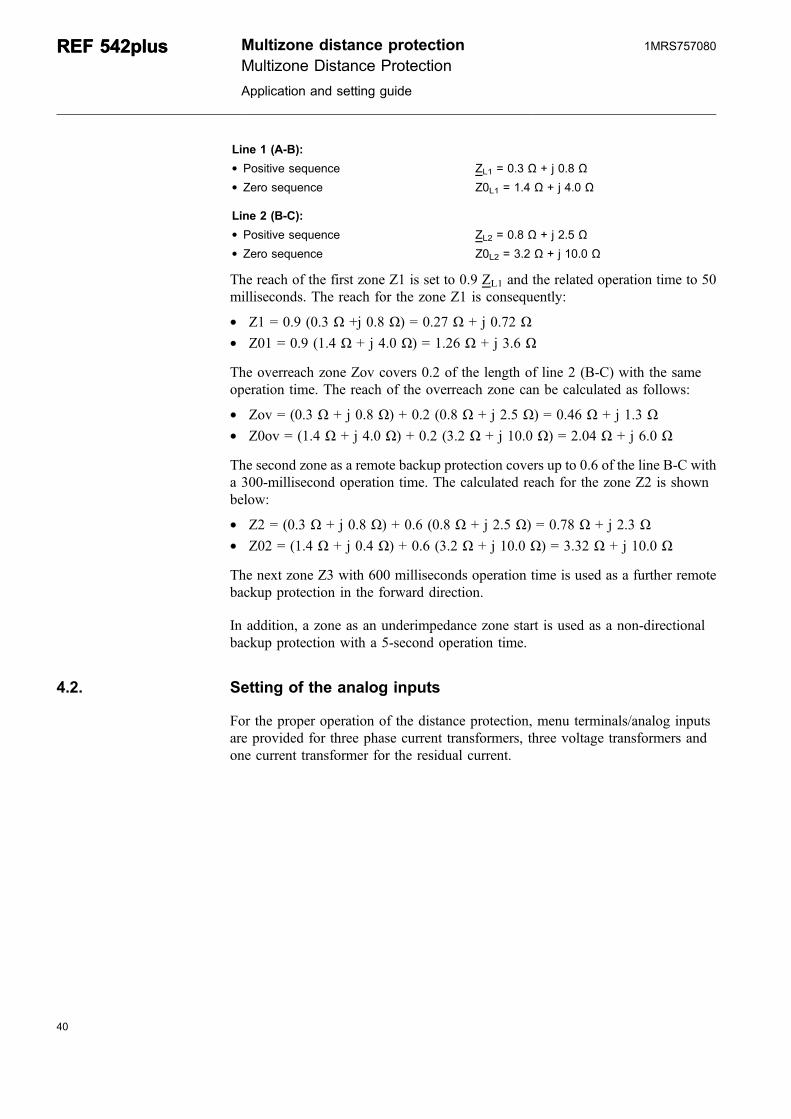
Line 1 (A-B):* Positive sequence ZL1 = 0.3 Ω + j 0.8 Ω* Zero sequence Z0L1 = 1.4 Ω + j 4.0 Ω
Line 2 (B-C):* Positive sequence ZL2 = 0.8 Ω + j 2.5 Ω* Zero sequence Z0L2 = 3.2 Ω + j 10.0 Ω
The reach of the first zone Z1 is set to 0.9 ZL1 and the related operation time to 50milliseconds. The reach for the zone Z1 is consequently:
* Z1 = 0.9 (0.3 Ω +j 0.8 Ω) = 0.27 Ω + j 0.72 Ω* Z01 = 0.9 (1.4 Ω + j 4.0 Ω) = 1.26 Ω + j 3.6 Ω
The overreach zone Zov covers 0.2 of the length of line 2 (B-C) with the sameoperation time. The reach of the overreach zone can be calculated as follows:
* Zov = (0.3 Ω + j 0.8 Ω) + 0.2 (0.8 Ω + j 2.5 Ω) = 0.46 Ω + j 1.3 Ω* Z0ov = (1.4 Ω + j 4.0 Ω) + 0.2 (3.2 Ω + j 10.0 Ω) = 2.04 Ω + j 6.0 Ω
The second zone as a remote backup protection covers up to 0.6 of the line B-C witha 300-millisecond operation time. The calculated reach for the zone Z2 is shownbelow:
* Z2 = (0.3 Ω + j 0.8 Ω) + 0.6 (0.8 Ω + j 2.5 Ω) = 0.78 Ω + j 2.3 Ω* Z02 = (1.4 Ω + j 0.4 Ω) + 0.6 (3.2 Ω + j 10.0 Ω) = 3.32 Ω + j 10.0 Ω
The next zone Z3 with 600 milliseconds operation time is used as a further remotebackup protection in the forward direction.
In addition, a zone as an underimpedance zone start is used as a non-directionalbackup protection with a 5-second operation time.
4.2. Setting of the analog inputs
For the proper operation of the distance protection, menu terminals/analog inputsare provided for three phase current transformers, three voltage transformers andone current transformer for the residual current.
40
REF 542plusREF 542plus Multizone distance protectionMultizone Distance Protection
Application and setting guide
1MRS757080
41
A100060
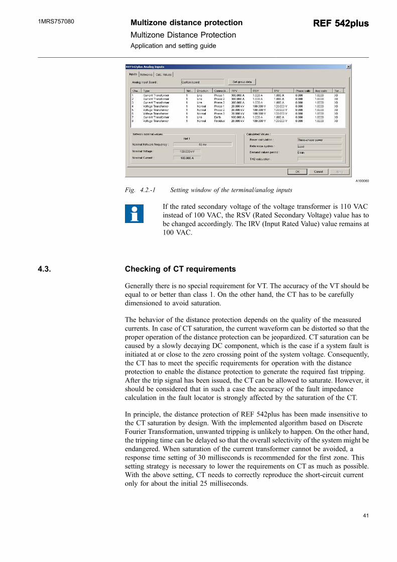
Fig. 4.2.-1 Setting window of the terminal/analog inputs
If the rated secondary voltage of the voltage transformer is 110 VACinstead of 100 VAC, the RSV (Rated Secondary Voltage) value has tobe changed accordingly. The IRV (Input Rated Value) value remains at100 VAC.
4.3. Checking of CT requirements
Generally there is no special requirement for VT. The accuracy of the VT should beequal to or better than class 1. On the other hand, the CT has to be carefullydimensioned to avoid saturation.
The behavior of the distance protection depends on the quality of the measuredcurrents. In case of CT saturation, the current waveform can be distorted so that theproper operation of the distance protection can be jeopardized. CT saturation can becaused by a slowly decaying DC component, which is the case if a system fault isinitiated at or close to the zero crossing point of the system voltage. Consequently,the CT has to meet the specific requirements for operation with the distanceprotection to enable the distance protection to generate the required fast tripping.After the trip signal has been issued, the CT can be allowed to saturate. However, itshould be considered that in such a case the accuracy of the fault impedancecalculation in the fault locator is strongly affected by the saturation of the CT.
In principle, the distance protection of REF 542plus has been made insensitive tothe CT saturation by design. With the implemented algorithm based on DiscreteFourier Transformation, unwanted tripping is unlikely to happen. On the other hand,the tripping time can be delayed so that the overall selectivity of the system might beendangered. When saturation of the current transformer cannot be avoided, aresponse time setting of 30 milliseconds is recommended for the first zone. Thissetting strategy is necessary to lower the requirements on CT as much as possible.With the above setting, CT needs to correctly reproduce the short-circuit currentonly for about the initial 25 milliseconds.
Multizone distance protection
Multizone Distance ProtectionApplication and setting guide
REF 542plusREF 542plus1MRS757080
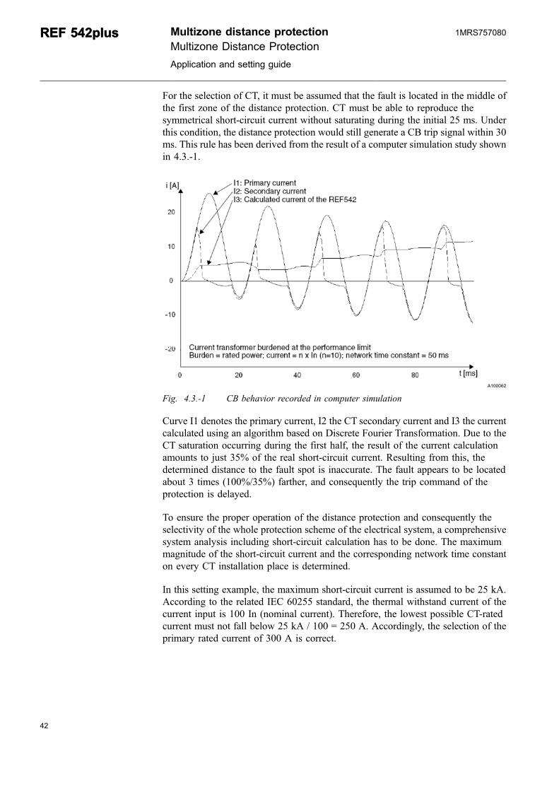
For the selection of CT, it must be assumed that the fault is located in the middle ofthe first zone of the distance protection. CT must be able to reproduce thesymmetrical short-circuit current without saturating during the initial 25 ms. Underthis condition, the distance protection would still generate a CB trip signal within 30ms. This rule has been derived from the result of a computer simulation study shownin 4.3.-1.
A100062
Fig. 4.3.-1 CB behavior recorded in computer simulation
Curve I1 denotes the primary current, I2 the CT secondary current and I3 the currentcalculated using an algorithm based on Discrete Fourier Transformation. Due to theCT saturation occurring during the first half, the result of the current calculationamounts to just 35% of the real short-circuit current. Resulting from this, thedetermined distance to the fault spot is inaccurate. The fault appears to be locatedabout 3 times (100%/35%) farther, and consequently the trip command of theprotection is delayed.
To ensure the proper operation of the distance protection and consequently theselectivity of the whole protection scheme of the electrical system, a comprehensivesystem analysis including short-circuit calculation has to be done. The maximummagnitude of the short-circuit current and the corresponding network time constanton every CT installation place is determined.
In this setting example, the maximum short-circuit current is assumed to be 25 kA.According to the related IEC 60255 standard, the thermal withstand current of thecurrent input is 100 In (nominal current). Therefore, the lowest possible CT-ratedcurrent must not fall below 25 kA / 100 = 250 A. Accordingly, the selection of theprimary rated current of 300 A is correct.
42
REF 542plusREF 542plus Multizone distance protectionMultizone Distance Protection
Application and setting guide
1MRS757080
43
A comprehensive power system analysis is needed. At first the impedance angle φsof the current and voltage quantities under short-circuit conditions is calculated. Inthis example, the impedance angle can be calculated from the given value of thenetwork time constant τ = 45 ms for the decaying DC component of the short-circuitcurrent. Due to the relation:
τ =ωXsRs
(8)
tanϕs XsRs
= (9)
the impedance angle can be determined by combining both equation as follows:
ϕ ωτ = Π °s arctan arctan( Hz ms= ⋅ ⋅ =2 50 45 85 95) . (10)
Then the source impedance of the incomer is to be estimated using the maximumshort-circuit current on the busbar as follows:
Zs UI
=⋅
=⋅
=rsc
kVkA3
203 25
0 46. Ω (11)
Based on the impedance angle, the reactance Xs and the resistance Rs can beestimated as follows:
Xs Zs s= =sin .ϕ Ω0 458 (12)
Rs Zs s= =cos .ϕ Ω0 032 (13)
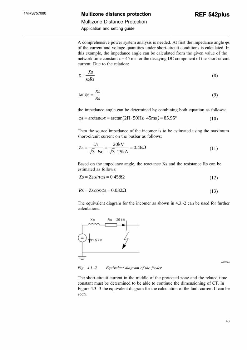
The equivalent diagram for the incomer as shown in 4.3.-2 can be used for furthercalculations.
A100064
Fig. 4.3.-2 Equivalent diagram of the feeder
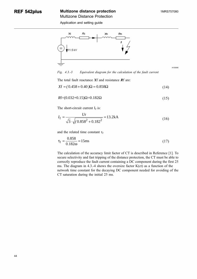
The short-circuit current in the middle of the protected zone and the related timeconstant must be determined to be able to continue the dimensioning of CT. InFigure 4.3.-3 the equivalent diagram for the calculation of the fault current If can beseen.
Multizone distance protection
Multizone Distance ProtectionApplication and setting guide
REF 542plusREF 542plus1MRS757080
A100066
Fig. 4.3.-3 Equivalent diagram for the calculation of the fault current
The total fault reactance Xf and resistance Rf are:
Xf = + =( . . ) .0 458 0 40 0 858Ω Ω (14)
Rf=(0.032+0.15) =0.182Ω Ω (15)
The short-circuit current If is:
I Uf
r kA=⋅ +
=3 0 858 0 182
13 22 2( . .
. (16)
and the related time constant τf
τωf ms= =0 858
0 18215.
.(17)
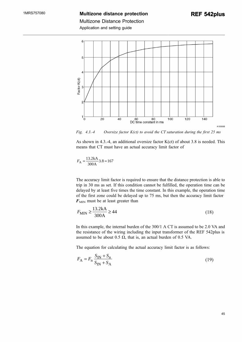
The calculation of the accuracy limit factor of CT is described in Reference [1]. Tosecure selectivity and fast tripping of the distance protection, the CT must be able tocorrectly reproduce the fault current containing a DC component during the first 25ms. The diagram in 4.3.-4 shows the oversize factor K(ct) as a function of thenetwork time constant for the decaying DC component needed for avoiding of theCT saturation during the initial 25 ms.
44
REF 542plusREF 542plus Multizone distance protectionMultizone Distance Protection
Application and setting guide
1MRS757080
45
A100068
Fig. 4.3.-4 Oversize factor K(ct) to avoid the CT saturation during the first 25 ms
As shown in 4.3.-4, an additional oversize factor K(ct) of about 3.8 is needed. Thismeans that CT must have an actual accuracy limit factor of
FAkAA
= =13 2300
3 8 167. .
The accuracy limit factor is required to ensure that the distance protection is able totrip in 30 ms as set. If this condition cannot be fulfilled, the operation time can bedelayed by at least five times the time constant. In this example, the operation timeof the first zone could be delayed up to 75 ms, but then the accuracy limit factorFMIN must be at least greater than
FMINkAA
≥ ≥13 2300
44.(18)
In this example, the internal burden of the 300/1 A CT is assumed to be 2.0 VA andthe resistance of the wiring including the input transformer of the REF 542plus isassumed to be about 0.5 Ω, that is, an actual burden of 0.5 VA.
The equation for calculating the actual accuracy limit factor is as follows:
F F S SS SA n
IN n
IN A= +
+ (19)
Multizone distance protection
Multizone Distance ProtectionApplication and setting guide
REF 542plusREF 542plus1MRS757080
Fn rated accuracy limit factor
FA actual accuracy limit factor
SIN internal burden of the CT secondary coil
Sn rated burden of CT
SA actual burden of CT
If a CT with a rated accuracy limit factor of 20 is to be used, the rated burden of theCT must be at least
S FF
S S SnA
nIN A IN
VA VA
= +( ) −
= +( ) −⎡⎣⎢
⎤⎦⎥
=16720
20 0 5 0 5 20 4. . .(20)
To ensure the correct operation of the distance protection, a CT with the followingtechnical specifications is recommended:
300 A/1 A, 20 VA, 5P20
If the rated power of the CT has to be reduced, a higher rated primary current mustbe selected.
4.4. Setting the distance protection
Depending on the number of zones needed, the related function blocks must beactivated in FUPLA by the configuration tool. The first function block is used forthe common setting of the distance protection. Afterwards, the zones for STARTand, depending on the required Impedance-Time-Characteristic, the related numberof function blocks for the zones are to be inserted.
4.4.1. System operation condition
The distance protection starts to operate if a certain current value is exceeded.Therefore, the setting Imin> is foreseen to define the minimum current flow. Asmentioned above, the minimum short-circuit current is 200 A and the nominal valueof CT is 300 A. Consequently, the setting of Imin> can be calculated by taking asafety margin 0.9 into account as follows:
Imin ln ln>= ⋅ =0 9 200 300 0 60. . (21)
46
REF 542plusREF 542plus Multizone distance protectionMultizone Distance Protection
Application and setting guide
1MRS757080
47
Imin> Minimum short-circuit current
In Nominal current of the CT as reference value
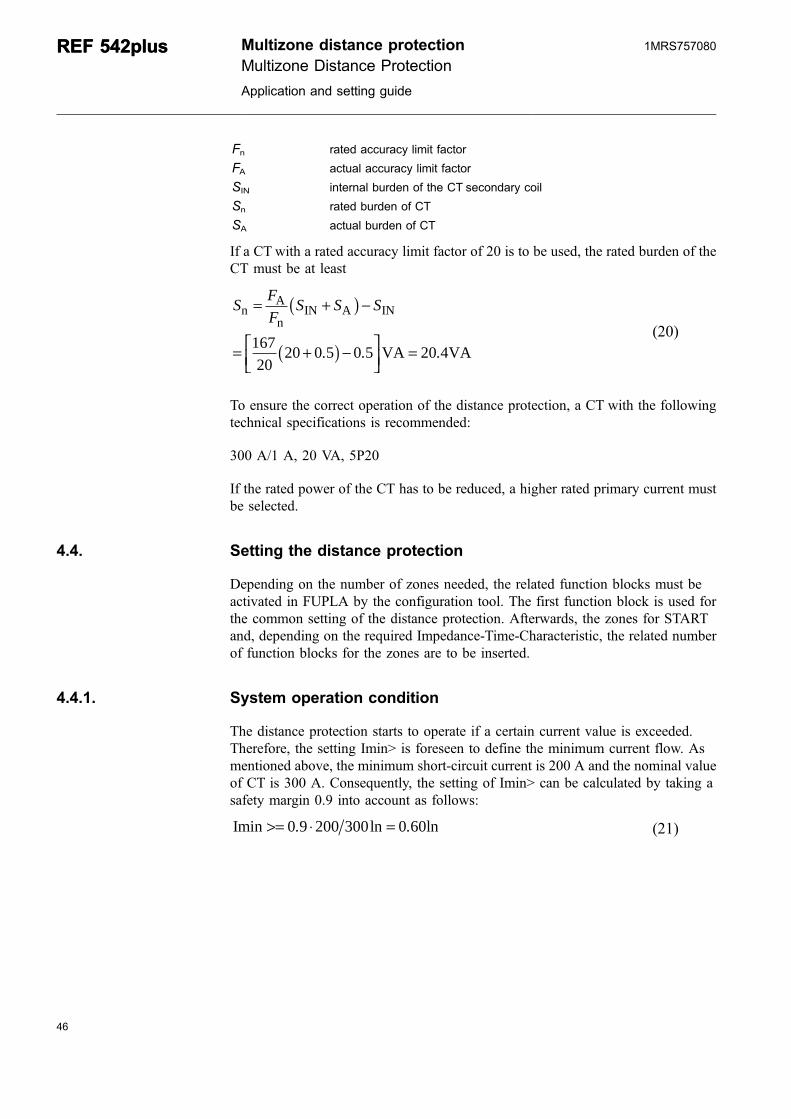
In order to detect an earth fault in the system, the setting of the residual current Io>and the residual voltage Uo> are provided too. For this example, the minimumresidual current is assumed to be 100 A. The setting of the residual current can becalculated as follows:
Io ln ln>= ⋅ =0 9 100 300 0 3. . (22)
Io> Residual overcurrent
In Nominal current as reference value
The setting of the residual voltage for this example is assumed to be:
Uo> = 0.2 Un
Uo> Nominal voltage as reference value
A100070
Fig. 4.4.1.-1 Setting for defining the operation condition
4.4.2. System neutral treatment
An important parameter to consider is the treatment of the system neutral whichrequires a specific behavior of the distance protection. In a system where the systemneutral is effectively earthed, all kinds of faults - earth faults, two-phase faults, twophase-to-earth faults and three-phase faults - must lead to a trip of CB. But if thesystem neutral is isolated or earthed by an earth fault compensation coil, an earthfault does not cause an operation of the distance protection. The system is designedin a way that an earth fault does not affect the system operation at all. Only in the
Multizone distance protection
Multizone Distance ProtectionApplication and setting guide
REF 542plusREF 542plus1MRS757080
cases where an earth fault has become a double-earth fault (additional earth fault atanother location), only one of the affected lines can be switched off. Since double-earth fault has changed to an earth fault, the system can be operated normally again.
A100072
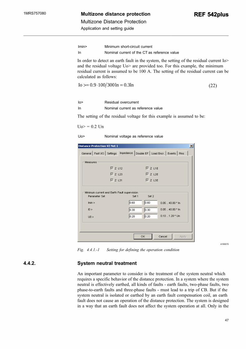
Fig. 4.4.2.-1 Setting of the network type
Here the distance protection operates in an MV system with an earth faultcompensation. Therefore, as shown in 4.4.2.-1, high ohmic must be selected as thenetwork type.
4.4.3. Phase selection
In a system with an earth fault compensation, it is required to have a specificbehavior for switching off a double earth fault. From the system operation point ofview, an earth fault can be tolerated. Thus, in case of a double earth fault, only oneof the affected line sections with an earth fault must be isolated.
48
REF 542plusREF 542plus Multizone distance protectionMultizone Distance Protection
Application and setting guide
1MRS757080
49
A100074
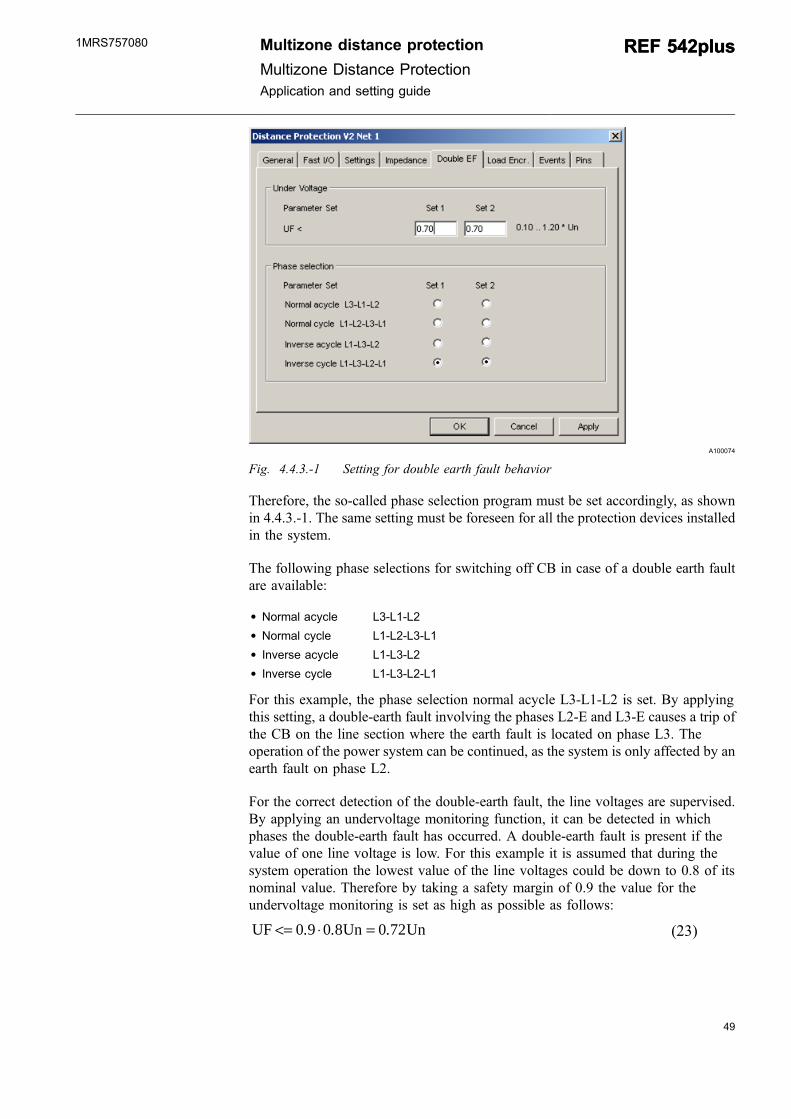
Fig. 4.4.3.-1 Setting for double earth fault behavior
Therefore, the so-called phase selection program must be set accordingly, as shownin 4.4.3.-1. The same setting must be foreseen for all the protection devices installedin the system.
The following phase selections for switching off CB in case of a double earth faultare available:
* Normal acycle L3-L1-L2* Normal cycle L1-L2-L3-L1* Inverse acycle L1-L3-L2* Inverse cycle L1-L3-L2-L1
For this example, the phase selection normal acycle L3-L1-L2 is set. By applyingthis setting, a double-earth fault involving the phases L2-E and L3-E causes a trip ofthe CB on the line section where the earth fault is located on phase L3. Theoperation of the power system can be continued, as the system is only affected by anearth fault on phase L2.
For the correct detection of the double-earth fault, the line voltages are supervised.By applying an undervoltage monitoring function, it can be detected in whichphases the double-earth fault has occurred. A double-earth fault is present if thevalue of one line voltage is low. For this example it is assumed that during thesystem operation the lowest value of the line voltages could be down to 0.8 of itsnominal value. Therefore by taking a safety margin of 0.9 the value for theundervoltage monitoring is set as high as possible as follows:
UF Un Un<= ⋅ =0 9 0 8 0 72. . . (23)
Multizone distance protection
Multizone Distance ProtectionApplication and setting guide
REF 542plusREF 542plus1MRS757080
UF< Undervoltage monitoring of the faulty line voltage
Un Nominal line voltage as reference value
4.4.4. Load encroachment
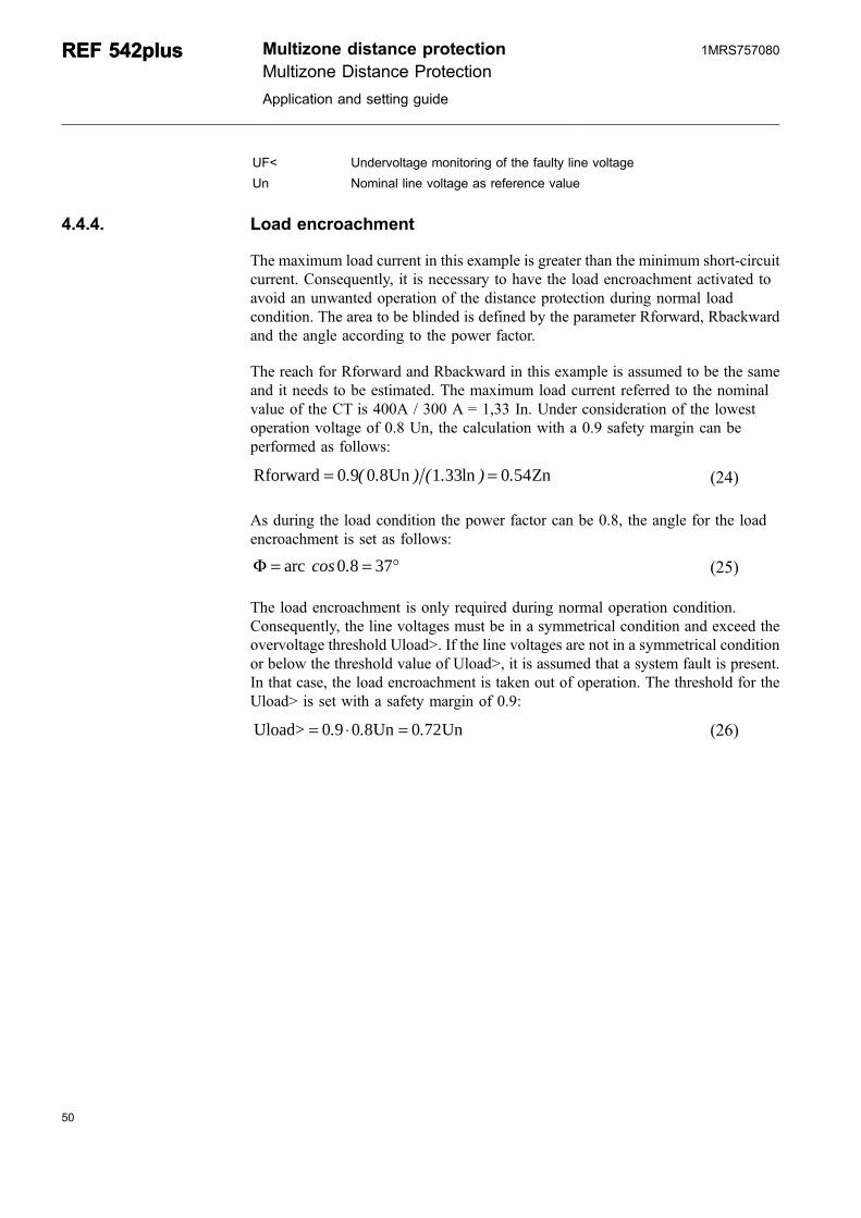
The maximum load current in this example is greater than the minimum short-circuitcurrent. Consequently, it is necessary to have the load encroachment activated toavoid an unwanted operation of the distance protection during normal loadcondition. The area to be blinded is defined by the parameter Rforward, Rbackwardand the angle according to the power factor.
The reach for Rforward and Rbackward in this example is assumed to be the sameand it needs to be estimated. The maximum load current referred to the nominalvalue of the CT is 400A / 300 A = 1,33 In. Under consideration of the lowestoperation voltage of 0.8 Un, the calculation with a 0.9 safety margin can beperformed as follows:
Rforward Un ln Zn= =0 9 0 8 1 33 0 54. ( . ) ( . ) . (24)
As during the load condition the power factor can be 0.8, the angle for the loadencroachment is set as follows:
Φ = °arc cos .0 8 37= (25)
The load encroachment is only required during normal operation condition.Consequently, the line voltages must be in a symmetrical condition and exceed theovervoltage threshold Uload>. If the line voltages are not in a symmetrical conditionor below the threshold value of Uload>, it is assumed that a system fault is present.In that case, the load encroachment is taken out of operation. The threshold for theUload> is set with a safety margin of 0.9:
Uload> Un Un= ⋅ =0 9 0 8 0 72. . . (26)
50
REF 542plusREF 542plus Multizone distance protectionMultizone Distance Protection
Application and setting guide
1MRS757080
51
A100076
Fig. 4.4.4.-1 Setting for the load encroachment
4.4.5. Underimpedance start zone
The new multizone distance protection can be designed for use with up to eightzones. Each zones is always activated as soon as the minimum current is present.Therefore, an underimpedance start zone, as used in the past to start the operation ofthe distance protection, is not needed anymore.
From the selectivity coordination point of view, the distance protection can be usedas a remote backup protection. Therefore, in most cases the start zone of the distanceprotection is used as a non-directional backup protection. Besides, the start signal isused for indication of the existing system fault.
For this example, one of the distance protection zones is used as an underimpedancenon-directional backup zone. The setting of the zone is defined with the minimumshort circuit current to be covered and the maximum operating voltage. As in thisexample with the minimum short-circuit current being (200 A / 300 A) In and themaximum operation voltage 1.1 Un, by taking into account a factor of 0.9 as asafety margin the reach for the operation characteristic can be calculated as follows:
Xforward Rforward Xbackward Rbackward
Un ln
= = =
= ( )⎡⎣ ⎤⎦ =1 1 2 3 0 9 1. . ..83Zn (27)
Multizone distance protection
Multizone Distance ProtectionApplication and setting guide
REF 542plusREF 542plus1MRS757080
A100078
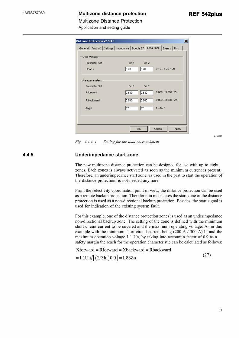
Fig. 4.4.5.-1 Setting for the operation of the zone start
A100080
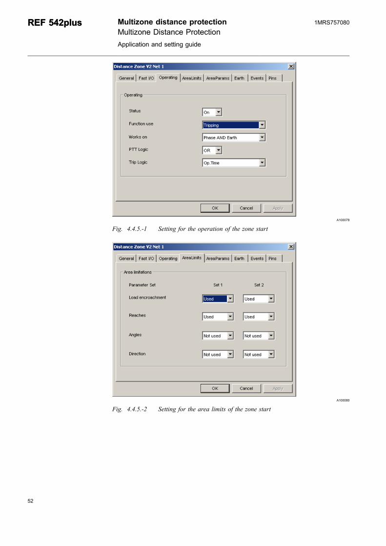
Fig. 4.4.5.-2 Setting for the area limits of the zone start
52
REF 542plusREF 542plus Multizone distance protectionMultizone Distance Protection
Application and setting guide
1MRS757080
53
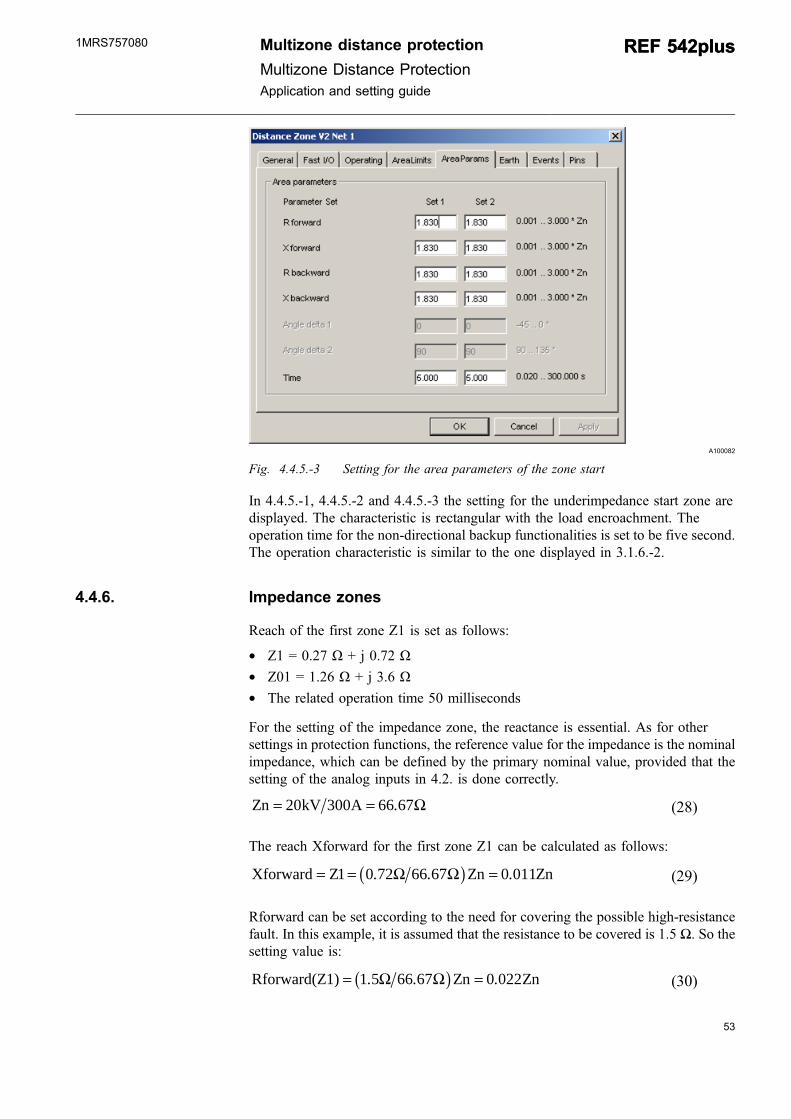
A100082
Fig. 4.4.5.-3 Setting for the area parameters of the zone start
In 4.4.5.-1, 4.4.5.-2 and 4.4.5.-3 the setting for the underimpedance start zone aredisplayed. The characteristic is rectangular with the load encroachment. Theoperation time for the non-directional backup functionalities is set to be five second.The operation characteristic is similar to the one displayed in 3.1.6.-2.
4.4.6. Impedance zones
Reach of the first zone Z1 is set as follows:
* Z1 = 0.27 Ω + j 0.72 Ω* Z01 = 1.26 Ω + j 3.6 Ω* The related operation time 50 milliseconds
For the setting of the impedance zone, the reactance is essential. As for othersettings in protection functions, the reference value for the impedance is the nominalimpedance, which can be defined by the primary nominal value, provided that thesetting of the analog inputs in 4.2. is done correctly.
Zn kV A= =20 300 66 67. Ω (28)
The reach Xforward for the first zone Z1 can be calculated as follows:
Xforward Z Zn Zn= = ( ) =1 0 72 66 67 0 011. . .Ω Ω (29)
Rforward can be set according to the need for covering the possible high-resistancefault. In this example, it is assumed that the resistance to be covered is 1.5 Ω. So thesetting value is:
Rforward(Z1) Zn Zn= ( ) =1 5 66 67 0 022. . .Ω Ω (30)
Multizone distance protection
Multizone Distance ProtectionApplication and setting guide
REF 542plusREF 542plus1MRS757080
A100084
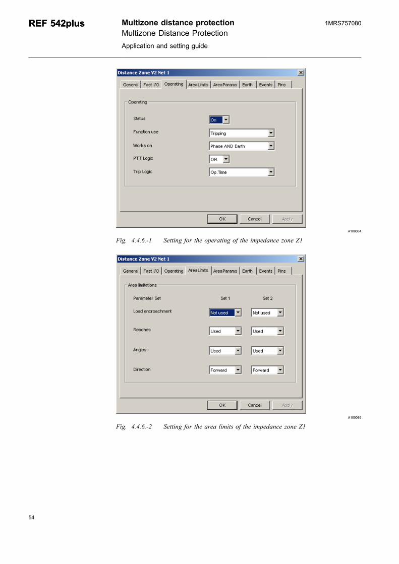
Fig. 4.4.6.-1 Setting for the operating of the impedance zone Z1
A100086
Fig. 4.4.6.-2 Setting for the area limits of the impedance zone Z1
54
REF 542plusREF 542plus Multizone distance protectionMultizone Distance Protection
Application and setting guide
1MRS757080
55
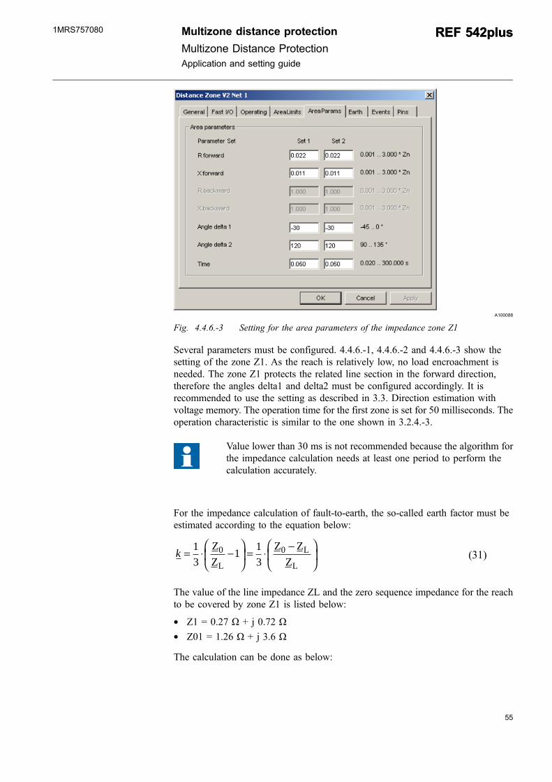
A100088
Fig. 4.4.6.-3 Setting for the area parameters of the impedance zone Z1
Several parameters must be configured. 4.4.6.-1, 4.4.6.-2 and 4.4.6.-3 show thesetting of the zone Z1. As the reach is relatively low, no load encroachment isneeded. The zone Z1 protects the related line section in the forward direction,therefore the angles delta1 and delta2 must be configured accordingly. It isrecommended to use the setting as described in 3.3. Direction estimation withvoltage memory. The operation time for the first zone is set for 50 milliseconds. Theoperation characteristic is similar to the one shown in 3.2.4.-3.
Value lower than 30 ms is not recommended because the algorithm forthe impedance calculation needs at least one period to perform thecalculation accurately.
For the impedance calculation of fault-to-earth, the so-called earth factor must beestimated according to the equation below:
k = ⋅ −⎛
⎝⎜
⎞
⎠⎟ = ⋅
−⎛
⎝⎜
⎞
⎠⎟
13
1 13
0 0ZZ
Z ZZL
L
L(31)
The value of the line impedance ZL and the zero sequence impedance for the reachto be covered by zone Z1 is listed below:
* Z1 = 0.27 Ω + j 0.72 Ω* Z01 = 1.26 Ω + j 3.6 Ω
The calculation can be done as below:
Multizone distance protection
Multizone Distance ProtectionApplication and setting guide
REF 542plusREF 542plus1MRS757080
Z Z01 1 1 26 0 27 3 6 0 72 0 99 2 88− = −( ) + −( )⎡⎣ ⎤⎦ −( ). . . . . .j jΩ = Ω (32)
After conversion in the polar coordinate, the result for
Modulus (Z01 – Z1) = 3.04 Ω
Angle (Z01 – Z1) = 71°
The same can be done for Z1 to concert in the polar coordinate.
Modulus (Z1) = 0.77 Ω
Angle (Z1) = 69°
Now the k faktor can be estimated:
Modulus (k for Z1) = (1/3) (3.04/0.77) = 1.31
Angle (k for Z1) = 71° – 69° = 2°
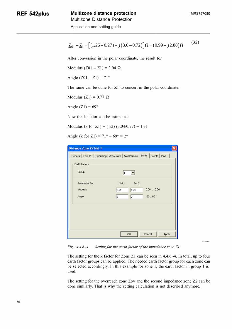
A100170
Fig. 4.4.6.-4 Setting for the earth factor of the impedance zone Z1
The setting for the k factor for Zone Z1 can be seen in 4.4.6.-4. In total, up to fourearth factor groups can be applied. The needed earth factor group for each zone canbe selected accordingly. In this example for zone 1, the earth factor in group 1 isused.
The setting for the overreach zone Zov and the second impedance zone Z2 can bedone similarly. That is why the setting calculation is not described anymore.
56
REF 542plusREF 542plus Multizone distance protectionMultizone Distance Protection
Application and setting guide
1MRS757080
57
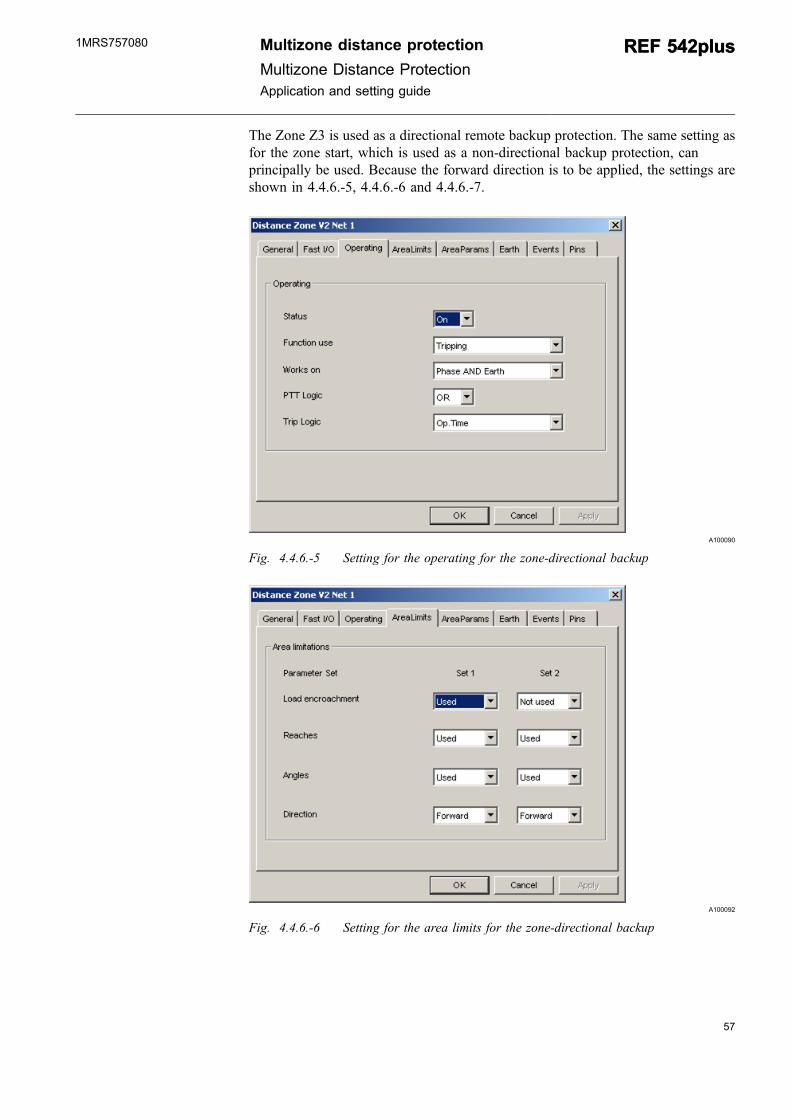
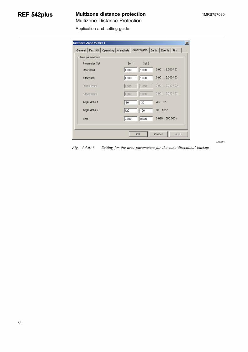
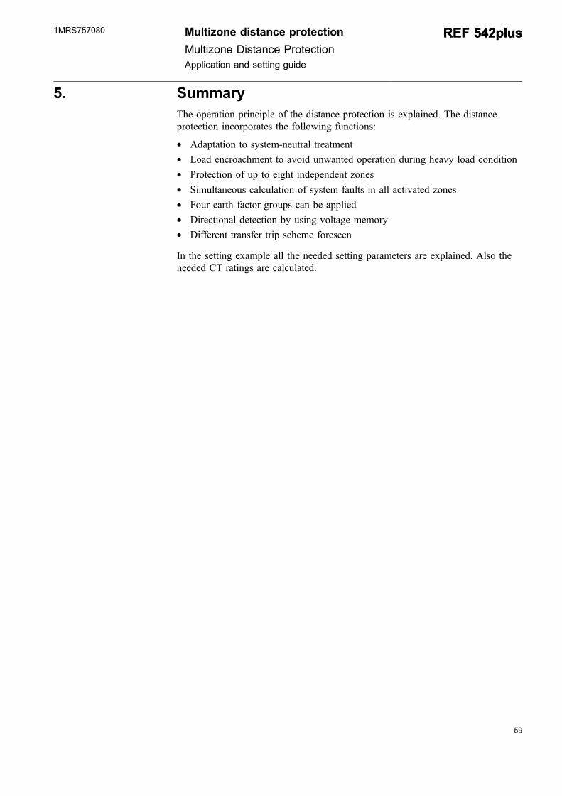
The Zone Z3 is used as a directional remote backup protection. The same setting asfor the zone start, which is used as a non-directional backup protection, canprincipally be used. Because the forward direction is to be applied, the settings areshown in 4.4.6.-5, 4.4.6.-6 and 4.4.6.-7.
A100090
Fig. 4.4.6.-5 Setting for the operating for the zone-directional backup
A100092
Fig. 4.4.6.-6 Setting for the area limits for the zone-directional backup
Multizone distance protection
Multizone Distance ProtectionApplication and setting guide
REF 542plusREF 542plus1MRS757080
A100094
Fig. 4.4.6.-7 Setting for the area parameters for the zone-directional backup
58
REF 542plusREF 542plus Multizone distance protectionMultizone Distance Protection
Application and setting guide
1MRS757080
59
5. SummaryThe operation principle of the distance protection is explained. The distanceprotection incorporates the following functions:
* Adaptation to system-neutral treatment* Load encroachment to avoid unwanted operation during heavy load condition* Protection of up to eight independent zones* Simultaneous calculation of system faults in all activated zones* Four earth factor groups can be applied* Directional detection by using voltage memory* Different transfer trip scheme foreseen
In the setting example all the needed setting parameters are explained. Also theneeded CT ratings are calculated.
Multizone distance protection
Multizone Distance ProtectionApplication and setting guide
REF 542plusREF 542plus1MRS757080

60
61
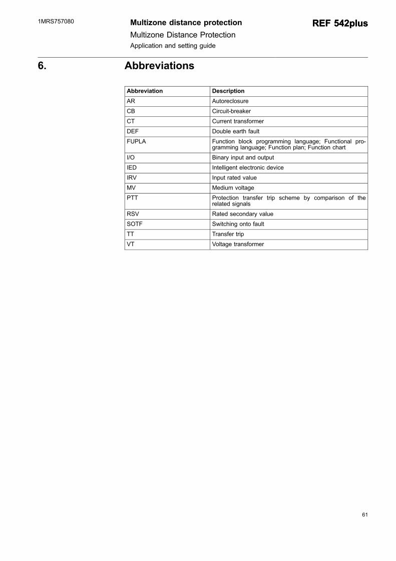
6. Abbreviations
Abbreviation Description
AR Autoreclosure
CB Circuit-breaker
CT Current transformer
DEF Double earth fault
FUPLA Function block programming language; Functional pro-gramming language; Function plan; Function chart
I/O Binary input and output
IED Intelligent electronic device
IRV Input rated value
MV Medium voltage
PTT Protection transfer trip scheme by comparison of therelated signals
RSV Rated secondary value
SOTF Switching onto fault
TT Transfer trip
VT Voltage transformer
Multizone distance protection
Multizone Distance ProtectionApplication and setting guide
REF 542plusREF 542plus1MRS757080

62
63
7. References[1] 1MRS755481 Calculation of the Current Transformer, Accuracy Limit Factor, ABB
Application Note
[2] 1MRS755860 Protection Functions, Configuration and Settings
[3] 1MRS756571 Autoreclosing REF 542plus
Multizone distance protection
Multizone Distance ProtectionApplication and setting guide
REF 542plusREF 542plus1MRS757080

64
65
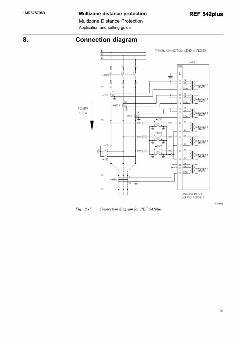
8. Connection diagram
A100166
Fig. 8.-1 Connection diagram for REF 542plus
Multizone distance protection
Multizone Distance ProtectionApplication and setting guide
REF 542plusREF 542plus1MRS757080


ABB OyDistribution AutomationP.O. Box 699FI-65101 VaasaFINLAND+358 10 2211+358 10 224 1080www.abb.com/substationautomation
1MRS757080
EN
1/2010