Embed Size (px)
Citation preview

i
MULTIVERB ALPHA 2.0 TABLE OF CONTENTS
INTRODUCTION................................................................. 1GETTING STARTED.............................................................. 2INSTALLATIO N................................................................. 3
CONNECTIONS............................................................ 3POWER .......................................................... . 3OUTPUT........................................................... 3MIDI I N.......................................................... 4MIDI OU T......................................................... 4MIDI THR U........................................................ 4PWR OUT.......................................................... 4
CONTROLS AND OPERATION....................................................... 4INPUT LEVEL INDICATOR S................................................. 4INPUT LEVEL CONTROL .................................................... 5OUTPUT LEVEL CONTROL ................................................... 5LIQUID CRYSTAL DISPLA Y................................................. 5
CONTROL BUTTONS.............................................................. 6FUNCTION BUTTONS....................................................... 6
PRESET........................................................... 7MIX .......................................................... . 7PARAM .......................................................... . 8VALUE .......................................................... . 8BYPASS........................................................... 8EDIT MODE........................................................ 9
EDIT MODE CONTROL BUTTONS.............................................. 9ENTER .......................................................... . 9RECALL ........................................................... 9ADD EFFECT....................................................... 9STORE ......................................................... . 11REC/ARM......................................................... 12TRIGGER......................................................... 12TITLE EDI T...................................................... 12UTILIT Y......................................................... 13
BYPASS LEVEL .............................................. 14REMOTE SWITCH 1 & 2 ....................................... 14AUTO PM DISPLAY........................................... 14LCD VIEW ANGLE............................................ 15SOFTWARE VERSION LEVEL .................................... 15PRESET MEMORY ALLOCATION.................................. 15RECALL FACTORY PRESET..................................... 15PRESET 1-115 LOCKED/UNLOCKED.............................. 16
MIDI ......................................................... . 16MIDI ENABL E............................................... 16MIDI CHANNEL .............................................. 16OMNI MODE................................................. 17MIDI PROGRAM TABLE........................................ 17FX ON/OFF ENABLE (USING X-15 ) ............................. 17MIDI EVENT DATA MONITORING MODE........................... 18PRESS ENTER TO: ........................................... 18
SEND A PRESET (18); SEND ENTIRE MIDI PROGRAM TABLE(18); SEND ALL PRESETS (18)
PERFORMANCE MIDI ............................................................ 18DESCRIPTION OF ALGORITHMS................................................... 20
SIGNAL FREQUENCY SHAPING ALGORITHMS................................... 20ACOUSTIC ENVIRONMENT SIMULATOR.................................. 21LOW PASS FILTE R................................................. 21
ii
PITCH TRANSPOSER................................................ 21DUAL PITCH TRANSPOSER........................................... 22
SWEPT OR MODULATED EFFECT ALGORITHMS.................................. 23FLANGER......................................................... 23CHORUS.......................................................... 23PANNER.......................................................... 24MIDI-PAN........................................................ 24TREMOLO......................................................... 24PHASER.......................................................... 25
NATURAL REVERBERATION ALGORITHMS...................................... 25REVERB-1........................................................ 25REVERB-2........................................................ 25REVERB-3........................................................ 26
GATED REVERBERATION ALGORITHMS........................................ 27GATE-VERB-1..................................................... 27GATE-VERB-2..................................................... 27GATE-VERB-3..................................................... 27
DELAY ALGORITHMS...................................................... 28TAP'D-DDL-S..................................................... 28TAP'D-DDL-L..................................................... 28REGEN-DDL-S..................................................... 29REGEN-DDL-L..................................................... 29STEREO-DDL-S.................................................... 29STEREO-DDL-L.................................................... 30SAMPLER-S....................................................... 30SAMPLER-L....................................................... 30SAMPLER+PTr..................................................... 31TUNER .......................................................... 32
How to use the Tuner...................................... 33MIDI DATA MONITOR........................................................... 34
PERFORMANCE MIDI DATA MONITOR......................................... 34MIDI EVENT MONITOR.................................................... 34
MISCELLANEOUS INFORMATION................................................... 37About the Presets..................................................... 37Battery Backup........................................................ 37Low Battery Indicator................................................. 37Software Revision Level ............................................... 37User Registration Card................................................ 37Factory Reset......................................................... 37Other Means of Bypassing the ALPHA 2.0................................ 38X-15 ................................................................ 38Contact Information................................................... 38Customer Service...................................................... 38
APPENDIX A.................................................................. 39APPLICATIONS.......................................................... 39
APPENDIX B.................................................................. 40EXAMPLES.............................................................. 40
Copying a preset................................................ 40Editing the MPT from the MULTIVERB ALPHA 2.0 front panelcontrols. ....................................................... 40Editing the MPT with a keyboard or external controller. ......... 40Increment Program............................................... 41
Setting up a preset sequence including a bypasspreset.............................................. 41
Programming the REMOTE jack for Incrementing Programs..... 42Adding Performance MIDI to an existing preset................... 42Controlling the Overall Level of an ALPHA 2.0 Preset ............ 43

iii
APPENDIX C.................................................................. 45MULTIVERB ALPHA 2.0 MIDI Messages..................................... 45System Exclusive Messages............................................. 45Detailed Description of Messages...................................... 46
APPENDIX D.................................................................. 47MIDI Implementation Chart ............................................. 47
APPENDIX E.................................................................. 48MIDI: Controllers & Numbers........................................... 48Default MIDI Controller Numbers....................................... 49
APPENDIX F.................................................................. 50DIAGRAMS.............................................................. 50
INSTRUMENT INTO MULTIVERB ALPHA 2.0 INTO TWO AMPLIFIERS......... 50GUITAR INTO MULTIVERB ALPHA 2.0 CONTROLLED BY ART X-15.......... 50STEREO EFFECTS SEND AND RETURN WITH MULTIVERB ALPHA 2.0......... 50
APPENDIX G.................................................................. 51Using the MULTIVERB ALPHA 2.0 With an X-15 ULTRAFOOT.................. 51
SPECIFICATIONS.............................................................. 52PRESET LIST................................................................. 53How to Read the Preset Description.......................................... 56
Table of Effect Abbreviations......................................... 56WARRANTY.................................................................... 56SERVICE INFORMATION......................................................... 56


1
INTRODUCTION
Thank you and congratulations on your new ART purchase. The MULTIVERB ALPHA 2.0is the first dazzling result of the new ART digital VLSI technology offering alevel of processing resolution with the sound quality of processors that used tocost thousands of dollars. This new technology boasts 24 bit architecture and anamazingly easy user interface. Some of the spectacular features of the ALPHA 2.0are listed next.
FEATURES:
* 20KHz bandwidth* New ASIC 24 bit digital integrated effects system* Over 50 effects to choose from* Built in Guitar/Bass tuner* Better than 90 dB signal to noise ratio* Multi-function rotary encoder* Over two octaves of pitch transposing* Multi interval pitch shifting* 200 memory locations* Pitch Transposer and Reverb combination* Sampling capabilities* Direct interface capability with the ART X-15 ULTRAFOOT* Full programmability of all parameters* Programmable mix and level* Digital contour* Stereo inputs and outputs* Phaser* Two assignable remote jacks* Power supply contained in unit* 9 volt DC output jack* Full MIDI system exclusive codes* Random access keypad* MIDI data monitor* Programmable 7 band equalizer
The MULTIVERB ALPHA 2.0 has the capability of providing you with a virtuallyendless number of sounds and effects. ART designed a combination of powerfulprocessing and ease of use into the MULTIVERB ALPHA 2.0. We strongly suggest youread and refer to this manual while getting used to your new processor.
Record for your reference:
DATE OF PURCHASE__________________________
PURCHASED FROM____________________________
SERIAL NUMBER_____________________________
SOFTWARE VERSION__________________________
471-5004-100

2
GETTING STARTED
We have included this section for those of you who can't wait to experience thesounds of your new ALPHA 2.0. Follow the hookup directions for the setup you useand then start playing. When you want to get to know your ALPHA 2.0 better, referto the rest of this manual for details, hints, and examples. Till later.....
Additional information to get you started can be found in Appendix A.
A hookup diagram can be found on page 42.
For all hookup combinations:
1) Center the slider controls.
2) The first 30 presets in the MULTIVERB ALPHA 2.0 show off some of the manycapabilities of the device. These patches include general purpose reverbs, reverbfor mixdown, an automatic tuner, multiple pitch effects, vocal delay, enhancers,and sampling, chorus, flange, phasing and other special effects. After that youwill find variations for different type sounds and effects. Some presets are setup for instant use with the ART X-15 ULTRAFOOT MIDI Controller. Use the X-15 tocontrol certain parameters in the preset. We encourage you to take the time tolisten to all the presets just so you can get a feel for the sounds and effectsyour MULTIVERB ALPHA 2.0 is capable of producing.
INSTRUMENT & GUITAR AMPPlug your instrument into the Left Input jack located on the rear panel. Connecta cable from your instrument amp input to the Left Output jack. Turn the ALPHA2.0 on first and then turn on your guitar amp. TURN DOWN THE LEVEL OF YOUR AMPbefore you play! Adjust your levels accordingly. If you are clipping your amp,back off on the Output Level of the ALPHA 2.0 with the Output slider.
INSTRUMENT & STEREO POWER AMPPlug your instrument into the Left Input jack located on the rear panel. Connecta two cables from your power amp to the Left and Right Outputs. If your power ampis mono, connect the left input of the amp to the Left Output jacks. Turn theALPHA 2.0 on first then turn on your power amp. Adjust the level with the Levelcontrol.

3
INSTALLATION
The MULTIVERB ALPHA 2.0 may be used in a variety of setups including: mixingconsoles with effect send and return facilities, in the effects loop of anamplifier, directly in line between a musical instrument and amplifier or mixerand in the tape loop of a home receiver. It is not recommended to use the deviceas a preamp.
Self contained in an all steel single high 19" rack mount case, the MULTIVERBALPHA 2.0 is designed for continuous professional use. For touring rackapplications, care should be taken to support the units rear if the rack might besubjected to mechanical shock. NOTE: The front panel may bend if no rear supportis provided. Mounting location is not critical, but for greater reliability werecommend that you not place the unit on top of power amps, tube equipment, orother sources of heat.
CONNECTIONS
POWERThis device is AC powered via a standard 3 conductor grounded power cable. Pluginto any standard AC receptacle. We recommend the use of a surge protector todecrease the chance of equipment damage due to voltage surges or spikes on theline. For your own safety as well as the safety of others, do not remove theground pin of the cable. Refer to the rear panel or the specifications for properoperating voltages.
All audio connections to the MULTIVERB ALPHA 2.0 are made at the rear of the unitvia professional 1/4" mono phone jacks. The MIDI connections are accomplished viafive pin "DIN" jacks on the rear panel. A 2.1mm female connector is the intendedplug to access the 9 volt DC output.
INPUTThe Left and Right inputs are single ended (unbalanced) with an impedance of 1Mohm. True stereo processing is accomplished by using both inputs in a left/rightapplication. If only one input is used, the signal is automatically routed toboth channels.
OUTPUTThe Left and Right outputs are single ended (unbalanced) with a source impedanceof 1.0K ohm, and can provide a stereo or mono output. When a true stereo signalis applied to the inputs, the resulting output is true stereo (dry signal only).If both outputs are used with a mono input signal, a stereo image is produced.Using one output with a mono or stereo source provides a mono signal combiningthe information from both outputs. If you do not want both output signalscombined (such as only one delay time required), plug a dummy plug (an open 1/4"plug) into the unused output.
NOTE: The effect output is a processed combination of both the left and rightinput signals.
A variety of input/output combinations may be used with the MULTIVERB ALPHA 2.0.One in one out (mono), one in two out (stereo image), two in one out (summedmono), and two in two out (true stereo) may be achieved.

4
NOTES:1) When using the MULTIVERB ALPHA 2.0 in the true stereo mode, only the drysignal will remain totally left and right orientated at the outputs. Theprocessed signal will be a mix of the inputs with its own individual stereo imageimposed by the algorithm used. This imitates the occurrence of naturalreverberation in a normal room.
2) When you use one of the inverted type Flanger algorithms or the Panner, makesure you are using both outputs (stereo out), if you're using only one outputyou'll get NO SOUND! This is because since the two outputs are opposite and theALPHA 2.0 sums the outputs, the signals cancel each other.
MIDI INThis jack receives the MIDI signal containing the MIDI messages. It enables youto "talk" to the ALPHA 2.0 from an external source such as an X-15 ULTRAFOOT, acomputer equipped with MIDI ports and associated software or a sequencer. AnyMIDI information sent to the MIDI In jack is echoed to the MIDI Thru jack. Whenusing the ALPHA 2.0 with an X-15 ULTRAFOOT, connect the MIDI cable to the 5 pinMIDI OUT jack on the X-15.
MIDI OUTThe MIDI output jack is used to transmit all MIDI control information from theMULTIVERB ALPHA 2.0 to whichever MIDI device is next in the chain. When using theALPHA 2.0 with an X-15 ULTRAFOOT, connect the MIDI cable to the 5 pin MIDI INjack on the X-15.
MIDI THRUA MIDI Thru jack is provided on the ALPHA 2.0 allowing you to continue a chain ofMIDI devices and let MIDI information pass "thru" the unit to the next one.Information leaving the Thru jack is a direct copy of the MIDI messages receivedat the MIDI In jack. The information is buffered so the integrity of the signalis not degraded when passing thru.
All MIDI Jacks are standard 5 pin DIN connectors utilizing standard MIDIconnections. No phantom power is present on the unused terminals. ART recommendsthese unused terminals remain unused.
PWR OUTThe Power Output jack located at the rear panel provides an OUTPUT voltage of(+)9 Volts DC. Use this jack to power external devices requiring a wall mountadapter. The ART X-11 and X-15 can be powered with this power jack. The jack willaccept a female connector with an inside diameter of 2.1mm. Do not plug in anyexternal power supply such as a wall mount adapter to this jack. Doing this maycause serious damage to your ALPHA 2.0 or quite possibly yourself!
CONTROLS AND OPERATION
INPUT LEVEL INDICATORSThree front panel LED's indicate signal at all times. They are labeled: PRES,NOM, and CLIP. These LED's display the status of the input signal after it haspassed the Input level control and the seven band equalizer. The bottom LED(PRES) is green and lights when a small amount of signal is seen by the ALPHA2.0. When you are operating with a nominal amount of signal the middle yellow LED(NOM) lights. Clipping is indicated by the top red LED (CLIP).
Adjust the amount of input level to operate the ALPHA 2.0 with the NOM LED litthe majority of the time. Allow for transients to light the CLIP LED

5
occasionally. If you find you are clipping the unit so the signal is distorted,simply reduce the signal level being sent to the MULTIVERB ALPHA 2.0 or decreasethe Input slide control slightly.
Be sure you are not causing the ALPHA 2.0 to clip with the equalizer. For properadjustment of level, review the Input Level Control section.
INPUT LEVEL CONTROLThe Input Level Control is located on the top right side of the front panel. Thisslide control adjusts the input signal to accommodate for a wide range ofdevices. Source inputs may range from musical instruments such as guitars andkeyboards, mixing consoles or effects loops in preamps and amplifiers. Whateverthe source, adjust the Input Level Control to light the NOM LED for the majorityof the time and allow for transients to light the CLIP LED occasionally.
With line level devices (mixers, some keyboards, effects loops) center the sliderand control the signal level from the effects send. Adjust the output level ofthe device sending the signal to the MULTIVERB ALPHA 2.0 so the CLIP LED isoccasionally lit on soft peaks. Use the Input Level control to compensate forminor level adjustments.
If the Input Level Control is not adjusted properly or the input source has a lowoutput level, noise and distortion will be heard at the output of the MULTIVERBALPHA 2.0.
OUTPUT LEVEL CONTROLThe Output Level Control adjusts the final output level of the MULTIVERB ALPHA2.0. With the slider fully to the left, there is no output signal present at theoutput jacks (0%). As you move the slider to the right the output signal level ofthe unit increases. When the slider is fully to the right, 100% output isachieved. Your output level most probably will be bumped a little up or down tocompensate for small increases or decreases in the processed signal level.
SEVEN SEGMENT DISPLAY(Red Numeric Display)The Seven Segment Display keeps you constantly informed of your Preset Number.Preset numbers are displayed from 001 to 200. When a preset is active the displayis stable. A flashing display indicates you are in Edit Mode and a preset isready to be recalled. The right decimal point will light to warn you yourinternal lithium battery is low and needs replacing. When using the Tuner, thisdisplay will become your tuning meter.
LIQUID CRYSTAL DISPLAY (LCD)All information relative to a preset indicated by the Seven Segment Display isdisplayed in the LCD. Backlighting of the display is provided for ease of use inlow light situations. The upper sixteen characters mainly display the PresetTitle (name). If no title has been assigned, the display will read "<blanktitle>". In some cases other information will be displayed here. The lowersixteen characters display mainly the number and abbreviated description ofeffects stored, effects to be selected or deleted in the preset, and effectparameter information. Other information may appear here also. The view angle maybe adjusted and is covered in the following section under the UTILITY function.
A user or factory preset would be displayed in the LCD like the followingrepresentation.

6
ÅÁÁÁÁÁÁÁÁÁÁÁÁÁÁÁÁÈÂ ALPHA 2.0 ÂÂ3 AES+CHO+REV 1 ÂËÁÁÁÁÁÁÁÁÁÁÁÁÁÁÁÁÎ
The title appears in the top half of the display. It may be up to sixteencharacters long.
In the center of the bottom half of the display, three letter abbreviations ofthe effects in the preset appear.
The number displayed at the bottom left side of the LCD indicates how manyeffects are present in the preset. A number at the far right of the bottom halfof the display indicates how many MIDI controllers are assigned to the presetwhen Performance MIDI is engaged.
A left or right arrow indicates more information is available for viewing. Toview the information, press the Value button and turn the Encoder left or right.
ÅÁÁÁÁÁÁÁÁÁÁÁÁÁÁÁÁÁÁÈÂ ALPHA 2.0 ÂÂ5 ←AES+CHO+REV 1→ÂËÁÁÁÁÁÁÁÁÁÁÁÁÁÁÁÁÁÁÎ
ENCODERThe rotary Encoder enables you to make fast and accurate changes to presets,parameters, and values accessible in each preset or function. You will notice theencoder will turn continuously in either direction. When adjusting values, youmay notice they sometimes "wrap" around to the beginning or end of their range.Other times when you reach a range end you will find you must go in the oppositedirection to return to the beginning. Each click of the Encoder will change theparameter value one step.
CONTROL BUTTONS
The buttons on the front panel engage or select the different functions of theALPHA 2.0. Modes of operation are indicated by LED's. When the LED is lit thefunction is active.
Ten of the control buttons serve a dual purpose. The split functions are setapart by color. While you are in the PRESET MODE (standard operating mode), allbuttons labeled in purple are active. When the EDIT MODE is engaged, the numberedkeypad entry buttons are used for preset effects control and utilities to beaccessed. These functions are labeled in grey.
FUNCTION BUTTONS
The function buttons are those which select a particular function or feature tobe executed or entered for modification. Status of the function button being inan active or inactive state is displayed by an LED next to the buttonidentification. The function is active when the LED is lit.

7
PRESETThe PRESET button, when pressed, engages Preset Mode. Once this button ispressed, all 200 presets may be accessed by either the keypad or rotary encoder.When the ALPHA 2.0 is first powered on, you are automatically in Preset Mode.Audio is being processed constantly while you are scrolling through the presetswith the encoder.
Two methods of Preset selection are used, scanning (with the ENCODER) and keypadentry. Selecting a preset with the encoder is easy. Scroll through the presets byturning the knob clockwise to go forward and counterclockwise to go backwards,the preset will instantly be recalled when you stop. Each click of the encoderwill change the preset value by one.
For instantaneous recall of the preset using the keypad buttons, select the exactpreset number. For example; if you want preset 196, locate the buttons shown onthe front panel labeled 0 through 9 (the numbers are reversed image in purple),enter 1-9-6, instantly you will see the LCD read title and preset information. Ifyou have audio hooked up you will notice the preset has been instantly recalled.If you enter two digits, there will be a slight pause before the preset isrecalled. Entering only one digit will not recall a preset.
MIXThink of the MIX control as a three channel mixer just before the output of theALPHA 2.0. To set the MIX you must access and change each parameter individually.Press the MIX button until the parameter you wish to adjust is highlighted inbrackets i.e.[EFX] then change the value with the Encoder. ÅÁÁÁÁÁÁÁÁÁÁÁÁÁÁÁÁÁÁÁÁÁÁÁÁÁÁÁÁÁÁÁÁÁÁÁÁÁÁÁÁÁÁÁÁÁÁÁÁÁÁÁÁÁÁÈ IN  ¸¶¶¶¶¶¶¶¹ ¸¶¶¶¶¶¶¶¹ ¸¶¶¶¶¶¶¹  >¶¶¶¶Ü¶¶½input ¼¶¶¶¾¶¶½ eq ¼¶¶¾¶¶½ efx ¼¶¶¹   º¶¶¶¶¶¶¶» · º¶¶¶¶¶¶¶» · º¶¶¶¶¶¶» ·   DRY · DRYEQ · EFX ·   · · ¸¶¶¶¶¶¶¶¶¶¿¶¶¶¶¶¶¶¶¹  OUT  · º¶¶½ PROGRAMMABLE ¼¶¶¶Ü¶¶¶¶¶>  º¶¶¶¶¶¶¶¶¶¶¶¶¶¶¶¶½ MIX ·   º¶¶¶¶¶¶¶¶¶¶¶¶¶¶¶¶¶¶»  ËÁÁÁÁÁÁÁÁÁÁÁÁÁÁÁÁÁÁÁÁÁÁÁÁÁÁÁÁÁÁÁÁÁÁÁÁÁÁÁÁÁÁÁÁÁÁÁÁÁÁÁÁÁÁÎ When the MIX button is pressed it engages the programmable mix function andallows you to set the level of the DRY, DIGITAL EFFECT and PRE-DIGITAL EQ signalspresent at the output. The three Mix parameters are displayed as DRY, EFX andDRYEQ. They control the amount of level present at the output of the ALPHA 2.0.For example, when the Dry value is set at 100%, and the Effect and Eq values are0%, the full dry signal and nothing else is present at the output(s). Afifty/fifty mix is achieved when both the DRY and FX values are equal to eachother. DRYEQ allows you to bring out the EQ'd sound to the final output before itis processed digitally. This could be helpful in making the signal morepronounced.
You do not need to engage the PARAM button to change the Mix parameters. Todisengage the MIX button, press either the Preset, Param or Value button.
DEFAULT VALUES: When you select a blank preset, the DRY and EFX levels are set at75%, and the DRYEQ is set at 0%.

8
The programmed Mix parameters may be stored as part of the preset. To save thevalues in each preset, press the STORE button.
You may also control the Mix parameters with an external MIDI controller such asthe ART X-15 ULTRAFOOT using the ALPHA 2.0's Performance MIDI.
CAUTION: If you have an Equalizer active in the preset its individual frequencylevels will have an impact on the mix setting by raising or lowering the level ofthe effect signal.
NOTE: Presets may have varying output levels due to a level control as one oftheir parameters. You may vary the individual effect output Level parameter todirectly change the apparent mix of the effect in the preset.
PARAMWhen you engage the PARAM button, effect parameters within the current presetmay be viewed. The ALPHA 2.0 automatically enters you into the EDIT mode when youselect the PARAM button. Selection of the parameters may be done with the Encoderor by pressing the Param button repeatedly.
When you are in MIDI or UTILITY mode, pressing the Param button will allow you toselect the available parameters with the Encoder knob or by pressing the Parambutton repeatedly.
While you are editing a preset, the Param button may be used as a cursor leftkey. Each time you press the button, the parameter value will scroll to the left.
VALUEEvery displayed parameter value in the ALPHA 2.0 may be changed. When the VALUEbutton is engaged, you automatically enter EDIT mode and are allowed to changethe parameter value using the Encoder. Press the STORE button to save any changesyou make.
While you are editing a preset, the Value button may be used as a cursor rightkey. Each time you press the button, the parameter values will scroll to theright.
Press the Value button and turn the Encoder left or right to view effectscontained in a preset. A diagonal left or right arrow in the LCD indicates moreinformation is available for viewing.
PROGRAMMING HINT: Press the Value button to change and view the parameters thenuse the Encoder to set the value. This way you don't have to switch between theParam and Value buttons to edit values.
BYPASSEngaging the BYPASS button kills the effect's signal and "zeroes" (sets the bandsflat) the EQ in the mix passing only dry signal to the outputs. When you firstpress the BYPASS button in either operating mode with a preset listed in the LCD,the display will first read [ **** BYPASS ****], then it will list the presetname. The LED associated with the button will flash to indicate you are in thebypass mode. Pressing BYPASS again returns the unit to the ACTIVE mode indicatedby the display [ ****ACTIVE****] for about two seconds and then just displayingthe preset name and effects. Bypass level is determined by the Bypass Levelparameter discussed in the Utility section.

9
NOTES:1) If the MIX parameters are programmed DRY = 0% and EFX = >0% and the BypassLevel Utility parameter is set to =MIX DRY LEVEL and BYPASS is initiated, nosignal will be present at the outputs.
2) If the DRYEQ is set at any level greater than 0% and Bypass is engaged, the EQis "zeroed" and a "flat" signal is present at the outputs. This holds true evenif DRY is set to 0%.
EDIT MODEEDIT MODE is engaged when you press the EDIT MODE button. All creation of presetsor preset parameter editing is done while in this mode. Titles, MIDI parameters,and Utilities are all accessed in Edit Mode. When in Edit Mode, all buttonsassociated with white lettering are active. All the control buttons work as well.
You may access all two hundred presets for modification or use while in EditMode. Edit Mode is automatically entered when you press either the PARAM or VALUEbuttons.
Previewing PresetsYou may preview presets while in Edit Mode by engaging the PRESET button. Use theEncoder to scan through the presets. Only the titles of the presets are shown, soit is helpful to know the contents. The processed output signal is not affected.To recall the preset when you are ready, press the RECALL button. Signal is beingprocessed through the last active preset. The reason for this is so you can setup for the next preset change when you want it to happen. When you stop scanning,the preset number in the Seven Segment Display will be flashing. If RECALL ispressed, the display will stop flashing indicating the preset is now active.
EDIT MODE CONTROL BUTTONS
ENTERUse the ENTER button when you want to complete an action such as adding an effectto a preset. When adding an effect there is a [?] after the name, press enter ifyou wish to insert this effect into your chain. A prompt (i.e. [ADD EQUALIZER ?])will appear in the LCD when it is necessary to press Enter to complete a task.
RECALLThe RECALL button is used to Recall presets while you are in Edit Mode. To Recalla preset (the Seven Segment Display will be flashing a Preset number), select theproper Preset and press the RECALL button. If you have been editing theparameters in a preset and wish to return them all to the original settings,press the Recall button.
ADD EFFECT Pressing the ADD EFFECT button once opens the Add Effect function.
To add an effect to a preset, press this button and use the Encoder to select theeffect you want to add to the chain. Turn the Encoder left or right to scanthrough your selections. Finalize the ADD EFFECT command (add the effect to thechain) by pressing the ENTER button. Doing this inserts the effect temporarily inmemory. If audio is passing through the ALPHA 2.0, you will hear the effect whenyou press the ENTER button. To make the effect permanent, press the STORE button.
To close the Add Effect function and escape to Edit Mode, press the button onceor press the Edit Mode button.

10
The Add Effect button is also used in the TITLE EDIT Mode to add characters andspaces to the title.
You can preview the effects you may add to an effect. MAKE SURE YOU ARE IN THEEDIT MODE, press the ADD EFFECT button once, notice the lower half of the LCDshows an available effect. The effects displayed as you turn the Encoder arethose available to be added to the effects chain.
It doesn't stop there! There are many sub variables of each effect to beexplored. Right now let's just worry about operation and not the effectsthemselves. To simplify matters let's step through an example depicting theselection of four effects. We will use some of the buttons not yet explained butdoing it this way will make the understanding of the programming much easier. Thecontrol buttons we use now will be defined in detail later in the manual.
Adding Effects to a PresetWhen you see text within the [ ] brackets, it is describing the text as itappears in the LCD.
-Enter EDIT MODE (press the Grey button).-Using the Encoder, GOTO preset 151 (the Preset LED should be lit).-Press the RECALL button [<blank title>, <no effects>].-Press the ADD EFFECT button once, [ADD:EQUALIZER?].-Press ENTER (you have just entered the eq into the chain), bottom display reads[1 EQL].-Press ADD EFFECT and turn the Encoder 8 clicks, [ADD:REVERB-1?].-Press ENTER (now the reverb algorithm is entered into the chain, display reads[2 EQL+REV].-Press ADD EFFECT again, select the ACU-ENV-SIM, enter it into the chain. (youpressed the ADD EFFECT button once and then pressed the ENTER button), displayshould read [3 EQL+AES+REV].-Press the ADD EFFECT button one more time and find then add REGEN-DDL-L! (Afteryou press the ADD EFFECT button once, use the Encoder).*Display reads [4 EQL+AES+DDL →]*IF YOU WISH TO SAVE THIS CHAIN OF EFFECTS AS A PRESET YOU MUST PRESS STORE NOW.-Press STORE.*The effects you have selected are now stored in preset 151.
You may have noticed a not equals sign at the bottom left hand side of the LCD.The not equals sign indicates the changes have been made to the original valuesof the preset. When Store is pressed this character disappears.
REMINDER: You have not set any parameters as of yet. Don't worry, we havepreselected a nominal value for each of the parameters associated with an effectas a starting point. This provides a user reference to a sound instead ofstarting at point zero. We feel it is useful to hear a descriptive set ofparameters so that you may tailor them to your own specific sound requirements.We'll look at these in just a moment as well as making a title for this preset.First, the DELETE key will be explained.

11
DELETE EFFECTPressing the DELETE EFFECT button once opens the Delete Effect function.
To delete an effect from a preset, press this button and use the Encoder toselect the effect you want deleted. Turn the Encoder left or right to scanthrough your selections. Finalize the DELETE EFFECT command (delete the effectfrom the chain) by pressing the ENTER button. Doing this deletes the effecttemporarily from memory. If audio is passing through the ALPHA 2.0, you will hearthe change when you press the ENTER button. Press the STORE button to make thechange permanent.
To close the Delete Effect function and escape to Edit Mode, press the buttononce or press the Edit Mode button.
The DELETE EFFECT button is also used in TITLE EDIT Mode to subtract charactersand spaces from the title.
Deleting Effects From a PresetWhen you see text within the [ ] brackets, it is describing the text as itappears in the LCD.
Recall preset 151, Press the EDIT MODE button, turn the encoder one click to theright and press STORE. You have just copied preset 151 into preset 152 so as notto lose preset 151 which we will use periodically through this manual.
-Press the DELETE EFFECT once. [DEL:EQUALIZER?]*Do you want to delete the equalizer? NO.-Turn the Encoder knob once click. [DEL:ACU-ENV-SIM?]*Let's delete this effect.-Press ENTER, [3 EQL+DDL+REV].*The effect has been eliminated but not permanently. You willaudibly hear the sound change when the effect is deleted.*Press STORE to make this change permanent.-Press STORE now.
With the elimination of an effect, you open up a space to insertanother effect or leave things as they are.
If you press the DELETE EFFECT button and there are no effects in the preset, thedisplay will read [DEL:NO FX TO DEL].
STOREAny time you wish to permanently save parameter values in a preset, press theSTORE button. All parameter values you have chosen will be stored into the presetas well as TITLE and MIX information. When you press the STORE button the LCDwill display [PRESET STORED]. If the phrase [LOCKED/SELECT LOCATION 111-200]appears don't panic, presets 1 through 110 are factory presets and though theparameters may be changed, the new values cannot be stored without firstUNLOCKING the presets (see UTILITY section).
TO DELETE A STORED PRESET, thereby releasing its memory to be used again, youmust store a null preset at the preset number you wish to delete. A null presetconsists of a blank title (all spaces, displayed as <blank title>) and no effects(displayed as <no effects>). Factory Preset 100 is programmed blank to make iteasy to delete stored presets. Presets 111 through 200 are null when you receiveyour unit or after a factory reset.

12
REC/ARMYOU MUST BE USING A PRESET SET UPFOR SAMPLING AND IN THE EDIT MODE FOR THIS FUNCTION TO OPERATE
While you are using any of the Sampler algorithms you will need to "reset" therecord parameter to be ready to record another sample. The REC/ARM button allowsyou to return the Sampler to Record-Ready status. Pressing this button wipes outthe existing sample and resets the length to the original stored preset value.
To reset the MULTIVERB ALPHA 2.0 to record a new sample, press the REC/ARMbutton.
TRIGGERYOU MUST BE USING A PRESET SET UPFOR SAMPLING AND IN THE EDIT MODE FOR THIS FUNCTION TO OPERATE
This button accesses two parameters for the Sampler algorithm. It allows you toeither record a sample of the program material or play back that portion (sample)of material you recorded.
When you first recall a Sampler preset it is usually geared up and ready torecord a sample. Most of the Factory Presets using the Sampler in the ALPHA 2.0are "record/ready". When the preset is recalled and signal is present to theALPHA 2.0, the record is automatically triggered. All you need to do is press theTRIGGER button to playback the sample.
Now you may replay this sample as recorded at any time by pressing the buttonagain. If the PLAY parameter is set in the SINGLE position and you hit the buttonquickly and repeatedly, you will get that stuttering "rap" effect. The sampledsound can be played back by hitting the button, MIDI, or using a footswitchconnected to a properly programmed REMOTE jack.
You may determine the length of the sample time regardless of what the Lengthparameter is set for in the Preset with this button. Say your Length is set for1.50 seconds and you feel the length should end at a specific point less than 1.5seconds. All you need to do is press the TRIGGER button once when you feel thesample should stop. This automatically sets the Length parameter for that amountof time.
NOTES:1) You will have to reset the LENGTH parameter back to its original value if thefull length is required. To do this simply hit the RECALL button, doing this willrestore the LENGTH parameter to its original value. (It is assumed the preset hasbeen STORED)
2) You cannot store the audio sample in the ALPHA 2.0 or dump them through MIDI.
TITLE EDITOne of the displays to appear in the upper portion of the LCD is the title of thepreset. There is a total of sixteen spaces with the complete ASCII character setavailable to use in naming presets.
To either edit the title or create a new one you must first enter the Edit Mode.-Press the Edit Mode button.-Press the Title Edit button.*[Title Edit] appears in the top half of the display and a cursor appears in thebottom half.

13
-Press the Value button and use the Encoder to select characters. If the Parambutton is pressed, you may move the cursor left and right with the Encoder toposition it for the next character.*Pressing the Value or Param buttons will move the cursor right or left one spaceat a time.-Press the Store button to save your title.
The title will appear in the upper half of the LCD and any selected effects arein the lower half. If you wish to change the title, enter the Title Edit Mode andmake the appropriate changes. Don't forget to STORE the new title.
If there are characters you wish to delete in the display use the Encoder to movethe cursor and then press the ADD or DELETE EFFECT button. If you wish to deleteall sixteen characters press the DELETE EFFECT or ADD EFFECT buttons sixteentimes. By doing this you will eliminate any characters and have a blank displayto start with.
The ADD EFFECT button can be used to add spaces to the title, the DELETE EFFECTbutton may be used to remove characters or spaces.
To exit or escape from the Title Edit mode, press the TITLE EDIT button once toescape to EDIT Mode or press the EDIT MODE button.
NOTE: When naming presets, try using descriptive titles relative to the preset.What the preset does, what sounds it makes, or what to use the preset for allwill make preset selections easier to locate and use.
UTILITYThe Utility button allows you to access the user programmable utilities available in the ALPHA 2.0 and view system information. Listed in this section isinformation regarding the variable utility parameters with their default valuesettings and ALPHA 2.0 system data.
To change Utilities, first enter Edit Mode then press the Utility button. Onceyou are in Utility Mode you may change values by selecting the parameter and thenchanging the value. To do this select the parameter you wish to modify witheither the Param or Value buttons. Use the Encoder to change the parameter value.(Make sure the Value LED is lit)
To view system data, press the Param or Value button until the information you'relooking for appears in the display. Remember the Param and Value buttons act as aleft and right cursor when they are pressed repeatedly.
You do not need to press the STORE button to save Utility parameters, it is doneautomatically when you exit Utility Mode.
To exit Utility Mode, press the Utility button to return to Edit Mode.
PROGRAMMING HINT: Press the Value button to change and view the parameters thenuse the Encoder to set the value. This way you don't have to switch between theParam and Value buttons to edit values.

14
BYPASS LEVEL [100%][0 to 100%] or [= MIX DRY LEVEL]
You may globally control the level of the signal of the Bypass signal when youbypass the ALPHA 2.0. The Bypass Level Utility parameter overrides whatever "DRY"level of the Mix set in each preset. Every time you Bypass the ALPHA 2.0, thethrough signal level will be whatever this value is set to. The initial defaultsetting is 75%.
When the value is set to [= MIX DRY LEVEL], the DRY level setting (from theProgrammable Mix) of the individual preset will be the signal level when theALPHA 2.0 is bypassed. Set your Bypass Level to avoid wild jumps in volume whenkicking the ALPHA 2.0 in and out.
REMOTE SWITCH 1 & 2[= BYPASS ON/OFF]
The REMOTE jacks may be programmed to either Bypass the ALPHA 2.0, access theIncrement or Decrement Preset mode, and Re-Arm or Trigger the Sampler. Afootswitch and any two conductor cable is intended to be used with these jacks.If you are using an ART X-15 ULTRAFOOT, you can use the Bypass Jack feature onthe X-15 to control one of the ALPHA 2.0's Remote Jacks. A momentary (normallyopen) switch should be used in applications other than the X-15's bypass feature.
Use the following chart to determine how the Remote Jacks may be programmed.
¸¶¶¶¾¶¶¶¶¶¶¶¶¶¶¶¶¶¶¶¶¾¶¶¶¶¶¶¶¶¶¶¶¶¶¶¶¶¶¹· # · REMOTE 1 · REMOTE 2 ·¼¶¶¶À¶¶¶¶¶¶¶¶¶¶¶¶¶¶¶¶À¶¶¶¶¶¶¶¶¶¶¶¶¶¶¶¶¶½· 0 · BYPASS ON/OFF · BYPASS ON/OFF ·· 1 · SAMPLE-TRIGGER · SAMPLE-TRIGGER ·· 2 · INCR PROGS 2 · SAMPLER-ARM ·· 3 · N/A (no value) · DECR PROGS ·º¶¶¶¿¶¶¶¶¶¶¶¶¶¶¶¶¶¶¶¶¿¶¶¶¶¶¶¶¶¶¶¶¶¶¶¶¶¶»
Either jack may be programmed for the Bypass feature, each time the footswitch isactivated (hot connected to ground) the BYPASS function is accessed and acts likethe Bypass button on the front panel.
The jacks may also be programmed to allow a footswitch to be used for accessingeither the Trigger or Re-Arm function when using the Sampler program. EitherRemote 1 or Remote 2 can be assigned as the Trigger and Remote 2 may be assignedas the Re-Arm.
These jacks may also be programmed to increment and decrement through a set ofpresets. Remote 1 may be set for incrementing up and Remote 2 may be set fordecrementing down. For decrement program to work, you must program Remote 1 forincrement. You can not program the Remote 2 jack for decrement alone.
AUTO PM DISPLAY [ALWAYS DISPLAYED]OFF, PRESET ONLY, ALWAYS DISPLAYED
This utility let's you set when the LCD displays Performance MIDI messages. Whenset to OFF, no message is displayed when the ALPHA 2.0 receives Performance MIDImessages. Preset Only allows messages to be displayed when in Preset Mode or whenediting a preset. Always Displayed means the MIDI message will be displayedwhenever the ALPHA 2.0 receives a (Performance) MIDI message.

15
NOTE: The ALPHA 2.0 always receives MIDI messages and responds to them. Only thedisplay is affected when setting this value.
LCD View Angle [6]
Allows the viewing angle of the LCD Display to be adjusted. You may change theLCD view angle for the best visibility. The angle may be adjusted to maximizereadability of the characters from top, front or under viewing angles. Whenviewing from the top, use a higher number. If you are viewing the displaydirectly from the front, use the middle numbers. Viewing the LCD when the ALPHA2.0 is above you, adjust the view angle to the lower numbers.
Software Version Level
Displays the software revision level currently installed in the MULTIVERB ALPHA2.0. The current version as well as the date will be displayed in the LCD. TheMULTIVERB ALPHA 2.0's software is contained in a socketed EPROM and is fieldreplaceable. This software controls the MULTIVERB ALPHA 2.0's functions as wellas its sounds. For your convenience write the software version in the spaceprovided on the Introduction page at the beginning of the manual.
Preset Memory AllocationMEMORY USED= ##AVAILABLE= ####
Displays how much user memory has been used and how much user memory is availablefor further storage.
This utility informs you how much User Preset Memory has been used or how muchmemory there is available for storing presets. When you first access user memorythere are approximately 5500 bytes (5.5 Kbytes) of space available. Each time youstore a preset more space is used up. If the display will inform you that thereis space available, but you are not allowed to store any more information, don'tworry. You have probably stored, deleted, edited or moved presets and informationthousands of times. The memory must be purged and reallocated. Save your presetsto a MIDI storage device and perform a factory reset then reload your presets.Previous unavailable memory space is now free for storing information.
Recall Factory PresetAllows you to recall any factory preset for comparison or editing purposes.
RECALLING A FACTORY PRESET-Make sure you are in the EDIT Mode. (Press EDIT button if not)-Press the UTILITY button.-Use the Encoder or Param and Value buttons to select screen reading [HIT RECALLFOR ART PRESET #]-Make sure the Value LED is lit.-Use the Encoder to select the preset you want to recall, i.e. Preset 96.-Press the RECALL button.
*Even though the title is not displayed in the LCD , the factory preset is nowactive, but, IT IS NOT PERMANENT . If you wish to make the preset permanent, youmust STORE it. To store the preset in the first 110 locations, you must firstunlock the existing preset. (See the next section about unlocking a preset) Ifyou are copying to a location above 110, press the STORE button now.-Press STORE, the preset is now stored into the location you selected.

16
Preset 1-115 Locked/UnlockedProtects the first 115 presets from being overwritten.
The factory presets may be unlocked for editing. When you set the value forUnlocked, all factory presets are unlocked and ready to edit. To relock thepresets, select the Locked value when you are done editing. At first you may notwant to overwrite the factory presets, so increment up to a user preset and storethe new preset.
UNLOCKING THE FACTORY PRESETS-Make sure you are in the EDIT Mode. (Press EDIT button if not)-Press the UTILITY button.-Press the Param button.-Use the Encoder to select the screen displaying [PRESET1...115 = LOCKED].-Change the Value to UNLOCKED.* All presets are now unlocked. If you wish to store new information in theFactory Presets, press the STORE button.
NOTE:Remember, when you unlock a preset, ALL presets are unlocked. To preventoverwriting presets, re-lock the presets following the directions to unlock apreset, only selecting the "LOCKED" value.
MIDIYou may gain access to all MIDI parameters and their values by pressing thisbutton. Shown here are the variable MIDI parameters and their default valuesettings.
Once you are in MIDI Mode you may change values by first selecting the parameterand then changing the value. To do this first press the PARAM button and selectthe parameter you wish to change with the Encoder. Next press the VALUE buttonand use the Encoder to select a new value. You do not need to press the STOREbutton to save the changes with one exception, it is done automatically when youexit MIDI Mode. You need to press the Store button if you edit the On/Off statusof an effect. To exit MIDI Mode, press the MIDI button to return to Edit Mode orthe Edit button.
PROGRAMMING HINT: Press the Value button to change and view the parameters thenuse the Encoder to set the value. This way you don't have to switch between theParam and Value buttons to edit values.
MIDI EnablePM= ON, OFF [ON]PROG= ON, OFF [ON]Allows you to turn on or off Performance MIDI and the Program change functionindependently. If you wish to use PM and not change presets, set PROG to = OFF.
MIDI ChannelOFF-16 [1]Sets MIDI send and receive channel number.

17
OMNI ModeON, OFF [ON]Sets MIDI OMNI mode on or off.
The MULTIVERB ALPHA 2.0 is shipped from the factory in OMNI mode, allowing it toreceive MIDI PROGRAM numbers on any MIDI channel.
MIDI Program Table[PROG= #][PRESET= #]
Allows you to edit the Midi Program Table (MPT).Refer to APPENDIX B for examples of editing the MPT and further documentation.
FX ON/OFF ENABLE (USING X-15)ON, OFF [ON]
When the MULTIVERB ALPHA 2.0 is used with an ART X-15 ULTRAFOOT, the two devices"talk" to each other. In order for the two devices to talk, Enable must be ON.The ALPHA 2.0 enables commands to be received from the X-15 to turn the effectsin the preset on or off.
NOTES:1) You must use two MIDI cables to communicate between the two units.2) If you are not using the ALPHA 2.0 with an X-15, set the Enable to OFF.
'ENTER' TO EDIT ON/OFF CONTROLLERS
The purpose of being able to edit the ON/OFF controllers is to allow you tochange effect status without an X-15 ULTRAFOOT. You may also change the MIDIcontroller number assigned to the effect.
Press the Enter button to set up the On/Off status of an effect in a preset. Theeffect status defaults to On when you first add the effect to the preset.
If you edit the On/Off status YOU MUST PRESS STORE TO SAVE YOUR CHANGES.
If you do not want an effect to be active instantly when a preset is recalled setthe Status to Off and press Store. When the preset is next selected, the effectwill be off. Access the EFFECT MODE of the X-15 and press the associatedactivator pad to turn on the effect.
¸¶¶¶¶¶¶¶¶¶¶¾¶¶¶¶¶¶¶¶¶¶¶¶¶¶¶¶¶¶¶¶¶¾¶¶¶¶¶¶¶¶¶¶¶¶¾¶¶¶¶¶¶¶¶¶¶¶¶¶¶¶¶¶¶¶¹· SWITCH # · PAD · STATUS * · MIDI CONTROLLER ·¼¶¶¶¶¶¶¶¶¶¶À¶¶¶¶¶¶¶¶¶¶¶¶¶¶¶¶¶¶¶¶¶À¶¶¶¶¶¶¶¶¶¶¶¶À¶¶¶¶¶¶¶¶¶¶¶¶¶¶¶¶¶¶¶½· 0 · BYPASS · OFF · MC 84:MIDI CNTLR ·· 1 · EXCITER · ON · MC 70:MIDI CNTLR ·· 2 · COMPRESSOR · ON · MC 71:MIDI CNTLR ·· 3 · DISTORTION · ON · MC 72:MIDI CNTLR ·· 4 · EQUALIZER · ON · MC 73:MIDI CNTLR ·· 5 · EXPANDER/NOISE GATE · ON · MC 74:MIDI CNTLR ·· 6 · REVERB · ON · MC 75:MIDI CNTLR ·· 7 · DELAY · ON · MC 76:MIDI CNTLR ·· 8 · PITCH TRANSPOSER · ON · MC 77:MIDI CNTLR ·· 9 · FLANGE/CHORUS · ON · MC 78:MIDI CNTLR ·· 10 · SPECIAL EFFECTS · ON · MC 79:MIDI CNTLR ·*The default status is On when the effect is selected.

18
MIDI Event data Monitoring ModeWhen you select this Mode, MIDI information is displayed in either easy to readand understand or technical terms. The LCD displays certain MIDI events as theyoccur, regardless of which MIDI channel is selected. Information displayed is theMIDI event itself, its attributes with a choice of display formats (in eitherdecimal or hexadecimal base 16).
For detailed information, please refer to the MIDI DATA MONITOR section.
PRESS ENTER TO:SEND A PRESETDump a single preset via MIDI to another MULTIVERB ALPHA 2.0 or MIDI storagedevice.
Sending a PresetTransferring a single preset to another MULTIVERB ALPHA 2.0 or a suitable MIDIdevice is accomplished by selecting the SEND A PRESET value and pressing theEnter button.
SEND ENTIRE MIDI PROGRAM TABLEDump entire MPT via MIDI to another MULTIVERB ALPHA 2.0 or MIDI storage device.
Sending MPT InformationTransferring the entire MPT to another MULTIVERB ALPHA 2.0 or a suitable MIDIdevice is accomplished by selecting the SEND ENTIRE MPT value and pressing theEnter button.
SEND ALL PRESETSDump all presets via MIDI to another MULTIVERB ALPHA 2.0 or MIDI storage device.
Sending all Preset InformationTransferring all presets to another MULTIVERB ALPHA 2.0 or a suitable MIDIdevice is accomplished by selecting the SEND ALL PRESETS value and pressing theEnter button.
IMPORTANT NOTE For:RECEIVING Preset and MPT InformationTo dump MIDI data into the MULTIVERB ALPHA 2.0 from either another MULTIVERBALPHA 2.0 or an external MIDI device you must make sure that the MIDI channelsmatch or OMNI mode is used. The MULTIVERB ALPHA 2.0 will accept MIDI data at alltimes regardless of what operating mode it is in.
PERFORMANCE MIDI [ PM]Performance Midi allows the MULTIVERB ALPHA 2.0 to have up to eight of itsparameters per preset controlled simultaneously via MIDI. Selection of theparameter to be controlled, the actual MIDI controller, the Scale of theadjustment ratio and the starting Center Point of the Scale may be programmedfrom the front panel.
When you are in Preset or Edit Mode, the LCD will inform you of eitherPerformance MIDI or FX ON/OFF information being received and what is beingchanged.
There is also a means to monitor MIDI information being sent to the MULTIVERBALPHA 2.0. While you are in the PM Mode you can select the MIDI Monitor utility
19
and verify MIDI data being sent to the device. Refer to the MIDI DataMONITORsection for additional information.
A table of MIDI controllers can be found in Appendix E, Tables and Charts.
Presets in the ALPHA 2.0 are set up to be controlled by Performance MIDI via theART X-15 ULTRAFOOT. See the section Operating the Multiverb ALPHA 2.0 with the X-15 ULTRAFOOT further on in this manual for more information. Don't let MIDI scareyou, using Performance MIDI in an ART device is easy. In most cases (especiallywith an X-15) you virtually plug in and play. But, if you want to program, we'vemade that easy too.
Modification to select the specific values and ranges you want the parameter tocover is done by normal editing. The number displayed in the upper left cornerrepresents the MIDI Controller you are working with.
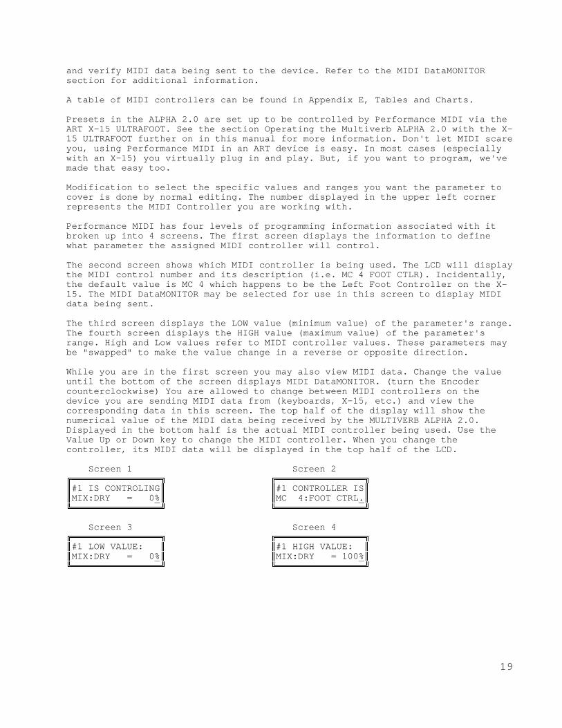
Performance MIDI has four levels of programming information associated with itbroken up into 4 screens. The first screen displays the information to definewhat parameter the assigned MIDI controller will control.
The second screen shows which MIDI controller is being used. The LCD will displaythe MIDI control number and its description (i.e. MC 4 FOOT CTLR). Incidentally,the default value is MC 4 which happens to be the Left Foot Controller on the X-15. The MIDI DataMONITOR may be selected for use in this screen to display MIDIdata being sent.
The third screen displays the LOW value (minimum value) of the parameter's range.The fourth screen displays the HIGH value (maximum value) of the parameter'srange. High and Low values refer to MIDI controller values. These parameters maybe "swapped" to make the value change in a reverse or opposite direction.
While you are in the first screen you may also view MIDI data. Change the valueuntil the bottom of the screen displays MIDI DataMONITOR. (turn the Encodercounterclockwise) You are allowed to change between MIDI controllers on thedevice you are sending MIDI data from (keyboards, X-15, etc.) and view thecorresponding data in this screen. The top half of the display will show thenumerical value of the MIDI data being received by the MULTIVERB ALPHA 2.0.Displayed in the bottom half is the actual MIDI controller being used. Use theValue Up or Down key to change the MIDI controller. When you change thecontroller, its MIDI data will be displayed in the top half of the LCD.
Screen 1 Screen 2ÅÁÁÁÁÁÁÁÁÁÁÁÁÁÁÁÁÈ ÅÁÁÁÁÁÁÁÁÁÁÁÁÁÁÁÁÈÂ#1 IS CONTROLING Â Â#1 CONTROLLER ISÂÂMIX:DRY = 0% Â ÂMC 4:FOOT CTRL. ÂËÁÁÁÁÁÁÁÁÁÁÁÁÁÁÁÁÎ ËÁÁÁÁÁÁÁÁÁÁÁÁÁÁÁÁÎ
Screen 3 Screen 4 ÅÁÁÁÁÁÁÁÁÁÁÁÁÁÁÁÁÈ ÅÁÁÁÁÁÁÁÁÁÁÁÁÁÁÁÁÈÂ#1 LOW VALUE: Â Â#1 HIGH VALUE: ÂÂMIX:DRY = 0% Â ÂMIX:DRY = 100% ÂËÁÁÁÁÁÁÁÁÁÁÁÁÁÁÁÁÎ ËÁÁÁÁÁÁÁÁÁÁÁÁÁÁÁÁÎ
20
DESCRIPTION OF ALGORITHMS
The MULTIVERB ALPHA 2.0 offers over sixty effects selections for you to choosefrom. Each effect may have several types to select for specifically narrowingdown the particular sound you are looking for. The algorithms are listed in fivecategories in the manual. These are: Signal Frequency Shaping, Swept or ModulatedEffect, Natural Reverberation, Gated Reverberation, Delay Algorithms andUtilities.
There are some digital categories that cannot be combined together. Rather thantell you which effects cannot be combined, the MULTIVERB ALPHA 2.0 automaticallyselects (or defaults) to which algorithms may be combined and displays them inthe LCD when you are "ADDing an EFFECT".
The algorithm name and abbreviation are shown in brackets [ ] under the effecttitle i.e. [EQUALIZER], [EQL]. Default settings for each parameter are shown inbold brackets [ ] at the beginning of the Parameter Values i.e. [0] .
NOTE: When setting up your own presets, select the digital effect you want mostin your effects chain first. By doing this, you are able to determine what othereffects may be combined with the selected effect.
SIGNAL FREQUENCY SHAPING ALGORITHMS
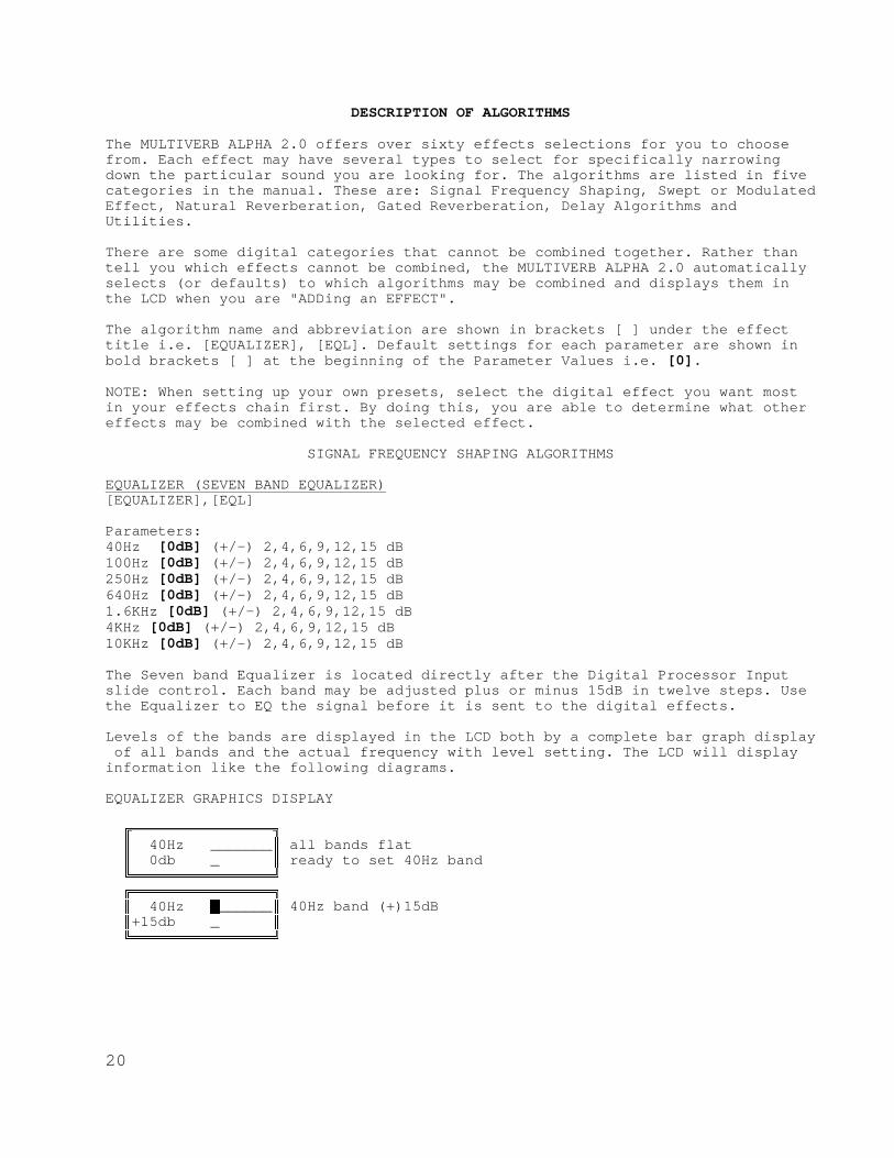
EQUALIZER (SEVEN BAND EQUALIZER)[EQUALIZER],[EQL]
Parameters:40Hz [0dB] (+/-) 2,4,6,9,12,15 dB100Hz [0dB] (+/-) 2,4,6,9,12,15 dB250Hz [0dB] (+/-) 2,4,6,9,12,15 dB640Hz [0dB] (+/-) 2,4,6,9,12,15 dB1.6KHz [0dB] (+/-) 2,4,6,9,12,15 dB4KHz [0dB] (+/-) 2,4,6,9,12,15 dB10KHz [0dB] (+/-) 2,4,6,9,12,15 dB
The Seven band Equalizer is located directly after the Digital Processor Inputslide control. Each band may be adjusted plus or minus 15dB in twelve steps. Usethe Equalizer to EQ the signal before it is sent to the digital effects.
Levels of the bands are displayed in the LCD both by a complete bar graph display of all bands and the actual frequency with level setting. The LCD will displayinformation like the following diagrams.
EQUALIZER GRAPHICS DISPLAY
ÅÁÁÁÁÁÁÁÁÁÁÁÁÁÁÁÁÈ Â 40Hz _______  all bands flat  0db _  ready to set 40Hz band ËÁÁÁÁÁÁÁÁÁÁÁÁÁÁÁÁÎ ÅÁÁÁÁÁÁÁÁÁÁÁÁÁÁÁÁÈ Â 40Hz à______  40Hz band (+)15dB Â+15db _  ËÁÁÁÁÁÁÁÁÁÁÁÁÁÁÁÁÎ

21
ÅÁÁÁÁÁÁÁÁÁÁÁÁÁÁÁÁÈ Â 100Hz à______ Â 40Hz band (+)15dB, 100Hz band (-)15dB Â-15db à Â ready to set 100Hz band ËÁÁÁÁÁÁÁÁÁÁÁÁÁÁÁÁÎ ÅÁÁÁÁÁÁÁÁÁÁÁÁÁÁÁÁÈ Â 10KHz ßßàß___Â 40Hz,100Hz,640Hz band (+)6dB, 250Hz (+)15dB Â 0db _ Â ready to set 10Khz band ËÁÁÁÁÁÁÁÁÁÁÁÁÁÁÁÁÎ
ACOUSTIC ENVIRONMENT SIMULATOR[ACU-ENV-SIM], [AES]
Parameter:[OFF] OFF, DEAD ROOM, HEAVY CARPET, WOOD/RUG MIX, DRAPE/CARPET,WOOD + TILE, PEWS/PEOPLE, WOOD BAFFLES, LT FLOOR RUG, CEILING DRAPE, STONECEILING, WALL DRAPES, NATURAL WOOD, OPEN AMBNCE
The Acoustic Environment Simulator (AES) allows you to simulate adding in bafflesor sound absorption materials to alter the high end response of your signal. Ofcourse this is a logical as well as necessary option, the NIGHTBASS reproducessound to 20KHz, well above normal natural ambiance.
Better than an equalizer, the AES program actually knocks out frequencies overthe entire spectrum, simulating real world acoustics. AES lets you warm up a roomor hall, deaden drums, soften a vocal, sizzle your ears off with presence, orjust make your material sound natural.
NOTE: When using AES alone, be sure to control its output level in the Mix withthe ANFX parameter. If you are only using AES and no digital effects you must usethis parameter to bring out the simulations at the output.
LOW PASS FILTER[LOW-PASS], [LPF]
Parameter:HF-CUT: = [THRU] THRU, 17.8K, 15.8K, 14.1K, 12.6K, 11.2K, 10.0K, 8.91K, 7.94K,7.08K, 6.31K, 5.62K, 5.01K, 4.47K, 3.98K, 3.55K, 3.16K, 2.82K, 2.51K, 2.24K,2.00K, 1.78K, 1.58K, 1.41K, 1.26K, 1.12K, 1.00K, 891Hz, 794Hz, 708Hz, 630Hz.
There is one algorithm defining the Low Pass Filter. This effect will always beplaced at the front of the digital effects chain so as to tailor the frequencyresponse of the effect and not the final product which should be further modifiedat the board. Thirty possible selections of roll-off frequencies are provided.
PITCH TRANSPOSER[PITCH-TRANS], [PTr]
Parameters::TYPE= [SMOOTH] OFF, SMOOTH, NORMAL, QUICK:PITCH = [0] (-)12 to (+)12 half steps in 1 half step increments:FINE = [0.00] (-)4.00 to (+)4.00 half steps in 0.06 (six cents) increments:BASE KEY = [OFF] OFF, 1 through 127 (key note on):REGENeration = [0%] 0 to 100 percent in % increments:LEVEL = [100%] 0 to 100 percent level in % increments
22
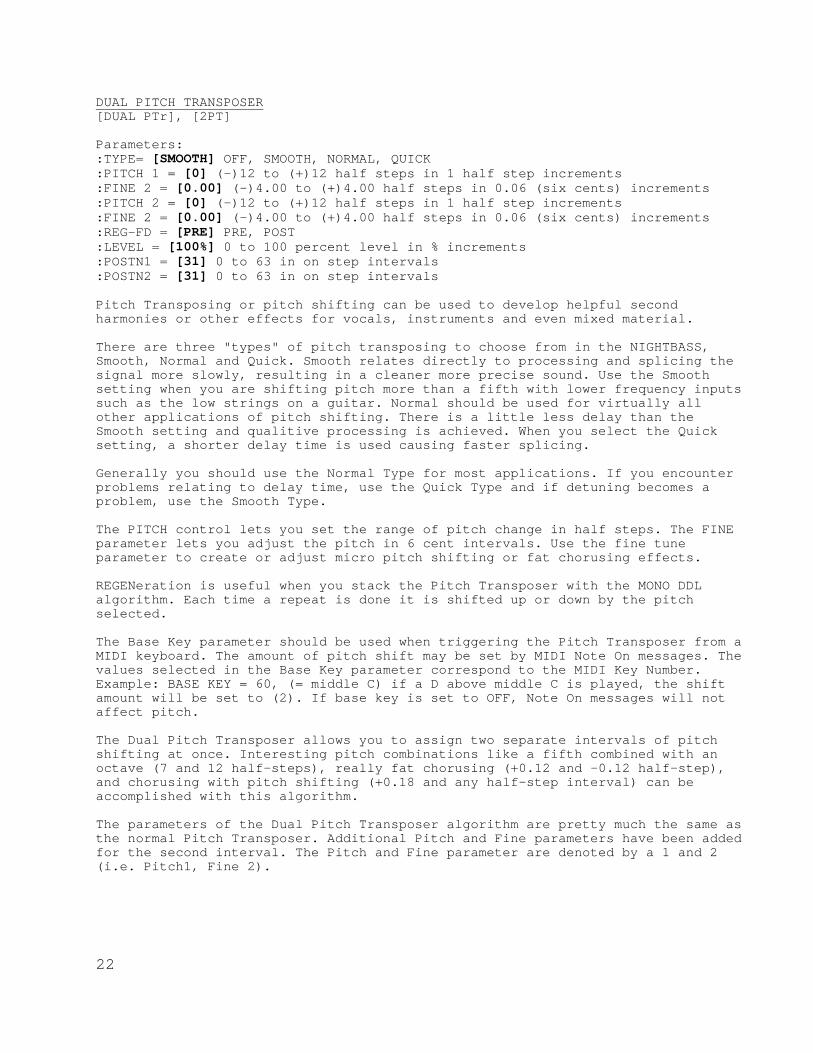
DUAL PITCH TRANSPOSER[DUAL PTr], [2PT]
Parameters::TYPE= [SMOOTH] OFF, SMOOTH, NORMAL, QUICK:PITCH 1 = [0] (-)12 to (+)12 half steps in 1 half step increments:FINE 2 = [0.00] (-)4.00 to (+)4.00 half steps in 0.06 (six cents) increments:PITCH 2 = [0] (-)12 to (+)12 half steps in 1 half step increments:FINE 2 = [0.00] (-)4.00 to (+)4.00 half steps in 0.06 (six cents) increments:REG-FD = [PRE] PRE, POST:LEVEL = [100%] 0 to 100 percent level in % increments:POSTN1 = [31] 0 to 63 in on step intervals:POSTN2 = [31] 0 to 63 in on step intervals
Pitch Transposing or pitch shifting can be used to develop helpful secondharmonies or other effects for vocals, instruments and even mixed material.
There are three "types" of pitch transposing to choose from in the NIGHTBASS,Smooth, Normal and Quick. Smooth relates directly to processing and splicing thesignal more slowly, resulting in a cleaner more precise sound. Use the Smoothsetting when you are shifting pitch more than a fifth with lower frequency inputssuch as the low strings on a guitar. Normal should be used for virtually allother applications of pitch shifting. There is a little less delay than theSmooth setting and qualitive processing is achieved. When you select the Quicksetting, a shorter delay time is used causing faster splicing.
Generally you should use the Normal Type for most applications. If you encounterproblems relating to delay time, use the Quick Type and if detuning becomes aproblem, use the Smooth Type.
The PITCH control lets you set the range of pitch change in half steps. The FINEparameter lets you adjust the pitch in 6 cent intervals. Use the fine tuneparameter to create or adjust micro pitch shifting or fat chorusing effects.
REGENeration is useful when you stack the Pitch Transposer with the MONO DDLalgorithm. Each time a repeat is done it is shifted up or down by the pitchselected.
The Base Key parameter should be used when triggering the Pitch Transposer from aMIDI keyboard. The amount of pitch shift may be set by MIDI Note On messages. Thevalues selected in the Base Key parameter correspond to the MIDI Key Number.Example: BASE KEY = 60, (= middle C) if a D above middle C is played, the shiftamount will be set to (2). If base key is set to OFF, Note On messages will notaffect pitch.
The Dual Pitch Transposer allows you to assign two separate intervals of pitchshifting at once. Interesting pitch combinations like a fifth combined with anoctave (7 and 12 half-steps), really fat chorusing (+0.12 and -0.12 half-step),and chorusing with pitch shifting (+0.18 and any half-step interval) can beaccomplished with this algorithm.
The parameters of the Dual Pitch Transposer algorithm are pretty much the same asthe normal Pitch Transposer. Additional Pitch and Fine parameters have been addedfor the second interval. The Pitch and Fine parameter are denoted by a 1 and 2(i.e. Pitch1, Fine 2).

23
A new parameter, Regeneration Feed ([RGN-FD]) controls where the digital delay's(if used) regeneration comes from. The insert point is either before (PRE) orafter (POST) the first voice. When the Stereo Digital Delay is used with the DualPitch Transposer and the RGN-FD is set to POST, the glissando effect of thenormal Pitch Transposer is the result. Use the PRE setting, for a simple predelaybefore the pitch shift occurs. Only the Short Stereo Delay is available for usewith the Dual Pitch Transposer.
The Position ([POSTN1 and 2]) parameter lets you set where in the sound fieldeach individual pitch is heard. The default setting is center field. When thevalue is 0, the signal appears full right. A value of 63 is full left.
SWEPT OR MODULATED EFFECT ALGORITHMS
FLANGER[FLANGER], [FLA]
Parameters::TYPE= [POST REVERB] FLANGER OFF, POST; REVERB, INV L, INV R, INV L+R, PRE; REVERB, INV L, INV R, INV L+R:WIDTH= [71%] 0 to 100 percent in % increments:SPEED= [0.84Hz] 0.04Hz to 27.3Hz:REGENeration= [76%] 0 to 100 percent in % increments:LEVEL= [100%] 0 to 100 percent in % increments
A wide range of flanging effects may be created with the MULTIVERB ALPHA 2.0.Normal and inverted flanging is available to you. An inverted flanger typereverses (inverts) one output from the other. The inverted types are listed asINV L and R, where L and R are Left and Right.
NOTE: When you use one of these inverted types, make sure you are using bothoutputs (stereo out), if you're using only one output you'll get NO SOUND! Thisis because since the two outputs are opposite and the ALPHA 2.0 sums the outputs,the signals cancel each other.
The base delay of the Flanger is set and the sweep WIDTH and SPEED is usercontrolled. REGENeration may be adjusted to vary the "strength" of the processedsignal. The output level of the FLANGER may be adjusted to control it's "depth"in the preset. When the Flanger TYPE= POST the flanger is positioned last in thechain. This is to assure that maximum effect and presence is maintained in alleffects combinations. Using Flanger TYPE= PRE positions the FLANGER in parallelwith any Reverb or DDL effect. By positioning the Flanger like this, theprocessed signal is not delayed or reverberated and then flanged.
CHORUS[CHORUS], [CHO]
Parameters::TYPE= [POST] OFF, POST, PRE,:WIDTH= [34%] 0 to 100 percent in % increments:SPEED= [0.84Hz] 0.04Hz to 27.3Hz:DELAY= [30ms] 0 to 47ms in 1 ms increments:LEVEL= [100%] 0 to 100 percent in % increments
Chorus may be used to thicken or sweeten the final processed sound. It is createdby sweeping a comb filter through a base delay time and generally using between a30 to 60 percent mix between the dry and wet signal. The base delay time plays

24
an important role in the perception of the effect. Longer base delays are morepreferable to give a deep rich sound to vocals and guitars, while shorter basedelays are used for more delicate enhancement purposes. The width plays animportant role in the range of perceived effect and is best used in conjunctionwith the speed parameter. Like the FLANGER, the effect type may either be POST orPRE located in relation to reverb or delay. The output level of the CHORUS may beadjusted to control it's "depth" in the preset.
PANNER[PANNER], [PAN]
Parameters::MOD % = [100%] 0 to 100 percent in % increments:SPEED= [2.16Hz] 0.04Hz to 27.3Hz
MIDI-PAN[MPN]Parameter:POSITN = [64] 0 to 127 in 1 step increments
Panning automatically pans the audio image from the left to the right in thestereo sound field. By varying the MODulation, you adjust the "depth" into thestereo field (how far left and right you go). The SPEED merely controls the rateat which you do so.
When you choose the Panner, the signal is automatically panned by the ALPHA 2.0from left to right at a depth and speed you have set. Choosing the MIDI-PANallows you to assign a MIDI Controller to change the signal's position with anExpression Pedal or other MIDI device.
NOTES:1) When using the panner, you should always set your MIX DRY level to 0%. Thisensures complete signal panning from left to right (full right-full signal... nosignal left and vice versa).2) When you use the Panner, make sure you are using both outputs, if you're usingonly one output you'll get NO EFFECT! This is because the two outputs are summedand the signals cancel each other.
TREMOLO[TREMOLO], [TRM]
Parameters::MOD % = [100%] 0 to 100 percent in % increments:SPEED= [2.16Hz] 0.04Hz to 27.3Hz
Tremolo creates an amplitude modulating effect at the output. The actual outputsignal level is being cut in and out at a certain rate. Use the MOD parameter tocontrol the depth of the Tremolo. Re-create the effect found on vintage as wellas current guitar amplifiers.
25
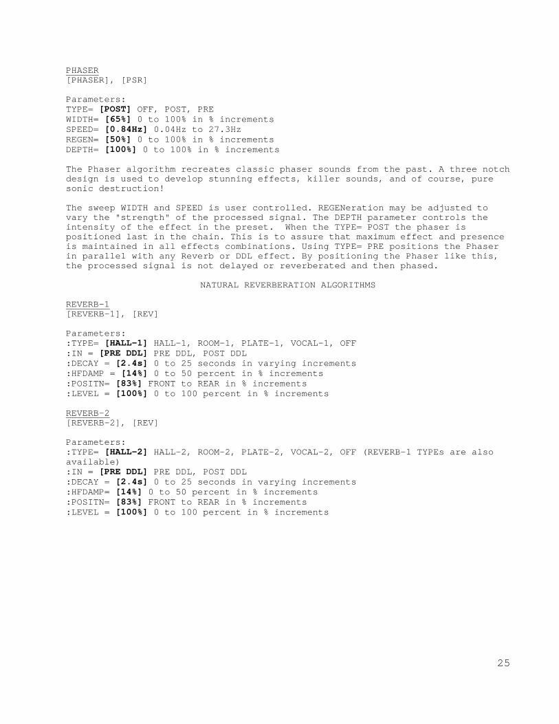
PHASER[PHASER], [PSR]
Parameters:TYPE= [POST] OFF, POST, PREWIDTH= [65%] 0 to 100% in % incrementsSPEED= [0.84Hz] 0.04Hz to 27.3HzREGEN= [50%] 0 to 100% in % incrementsDEPTH= [100%] 0 to 100% in % increments
The Phaser algorithm recreates classic phaser sounds from the past. A three notchdesign is used to develop stunning effects, killer sounds, and of course, puresonic destruction!
The sweep WIDTH and SPEED is user controlled. REGENeration may be adjusted tovary the "strength" of the processed signal. The DEPTH parameter controls theintensity of the effect in the preset. When the TYPE= POST the phaser ispositioned last in the chain. This is to assure that maximum effect and presenceis maintained in all effects combinations. Using TYPE= PRE positions the Phaserin parallel with any Reverb or DDL effect. By positioning the Phaser like this,the processed signal is not delayed or reverberated and then phased.
NATURAL REVERBERATION ALGORITHMS
REVERB-1[REVERB-1], [REV]
Parameters::TYPE= [HALL-1] HALL-1, ROOM-1, PLATE-1, VOCAL-1, OFF:IN = [PRE DDL] PRE DDL, POST DDL:DECAY = [2.4s] 0 to 25 seconds in varying increments:HFDAMP = [14%] 0 to 50 percent in % increments:POSITN= [83%] FRONT to REAR in % increments:LEVEL = [100%] 0 to 100 percent in % increments
REVERB-2[REVERB-2], [REV]
Parameters::TYPE= [HALL-2] HALL-2, ROOM-2, PLATE-2, VOCAL-2, OFF (REVERB-1 TYPEs are alsoavailable):IN = [PRE DDL] PRE DDL, POST DDL:DECAY = [2.4s] 0 to 25 seconds in varying increments:HFDAMP= [14%] 0 to 50 percent in % increments:POSITN= [83%] FRONT to REAR in % increments:LEVEL = [100%] 0 to 100 percent in % increments

26
REVERB-3[REVERB-3], [REV]
Parameters::TYPE= [HALL-3] HALL-3, ROOM-3, PLATE-3, VOCAL-3, OFF(REVERB-1 and REVERB-2 TYPEs are also available):IN = [PRE DDL] PRE DDL, POST DDL:DECAY = [2.4s] 0 to 25 seconds in varying increments:HFDAMP= [14%] 0 to 50 percent in % increments:POSITN= [67%] FRONT to REAR in % increments:DIFFUS= [100%] 40 to 100 percent in four % increments:LEVEL = [100%] 0 to 100 percent in % increments
REVERB-1 algorithms are best used when you are using multiple effects. They haveless density and are more suited to effects where the reverb is not the maineffect but is used for presence.REVERB-2 algorithms use more delay and have a higher complexity than the REVERB-1. REVERB-3 algorithms are the most complex and dense. Always use REVERB-3 whenbuilding "reverb only" programs.
The TYPEs of reverb are what make up the reverberant space. The smallest space isthe Plate. Generally this reverberant sound is used for tight and harsh soundingreverb. Room and Vocal types are the next size spaces. They tend to be a littlelooser allowing the sound to "bounce" around more adding color to the sound. TheHall types are the largest allowing you to fill in the spaces with reflectionsand build up density.
Once you decide what type of space is required, the length of DECAY is selected.Generally the size of the space is proportional to the time it takes the signalto decay. The larger the space, the longer the decay. Don't stick to this rule!Many quality sounds are made by bending the rules and allowing for creativity.
Since reverberant spaces tend to boost high frequencies the High FrequencyDamping (HFDAMP) parameter allows you to damp out frequencies as natural dampingwould in a reverberant space. Putting up baffles, carpeting, drapes or wood inthe space is what this parameter simulates. The higher the value, the moredamping.
Position (POSITN) puts you as a listener where you would hear the sound if youwere in the space. Front positions you closest to the initial signal so you heremore 1st reflections and the reverberant decay is in the background. As youposition yourself more towards the Rear, you "mix" the initial sound toreverberant sound ratio. At the Rear of the space, you hear the signal decay withall the reflections and very little initial sound.
Diffusion (DIFFUS) is how much the sound bounces around in the space. The lowerdiffusion % is looser and the smoothest at 100%.
LEVEL adjusts the effect level of the preset.

27
GATED REVERBERATION ALGORITHMS
GATE-VERB-1[GATE-VERB-1], [GAT]Gated Reverb
Parameters::TYPE= [SLOPE-1] SLOPE-1, FLAT-1, RVRS-1A, RVRS-1B, OFF:IN = [PRE DEL] PRE DDL, POST DDL:DECAY = [0.25s] 0 to 0.25 seconds in :DECAY = 0.05 to 0.25 ms in 5 ms increments:DIFFUS= [100%] 60 to 100 percent in four increments of 20%:LEVEL = [100%] 0 to 100 percent in % increments
GATE-VERB-2[GATE-VERB-2], [GAT]Gated Reverb
Parameters::TYPE= [SLOPE-2] SLOPE-2, FLAT-2, RVRS-2A, RVRS-2B, OFF:IN = [PRE DDL] PRE DDL, POST DDL:DECAY = [0.40s] 0.05 to 0.40 seconds in 5 ms increments:DIFFUS= [100%] 60 to 100 percent in four increments of 20%:LEVEL = [100%] 0 to 100 percent in % increments
GATE-VERB-3[GATE-VERB-3], [GAT]Gated Reverb
Parameters::TYPE= [SLOPE-3] SLOPE-3, FLAT-3, RVRS-3A, RVRS-3B:DECAY = [0.40s] 0.05 to 0.40 seconds in 5 ms increments:DIFFUS= [100%] 60 to 100 percent in four increments of 20%:LEVEL = [100%] 0 to 100 percent in % increments
Both GATE-VERB-1 and GATE-VERB-2 have forward and reverse gated reverb algorithmswhich are not quite as dense or complex as those found in the GATE- VERB-3algorithms. For an equal decay, GATE-VERB-1 is denser than GATE-VERB-2. Thedecay times found in GATE-VERB-2 are longer. When used in a stack of effectsthese gated sounds will fill in nicely. If you choose to use these effects alone,they will be loose and moderately sparse. By varying the amount of diffusion youdirectly affect the tightness (or looseness) of the sound. High diffusion equatesto a tighter effect.
GATE-VERB-3 algorithms are the most complex and dense. Always use GATE-VERB-3when building "reverb only" programs.The difference between normal reverb decays and decays when a gated program isthe normal decay gradually fades into nothing while the gated decay ends in anabrupt manner. The most interesting gated program is the flat setting. Here thereis no decay but the equivalent of a short burst of sound.

28
DELAY ALGORITHMS
TAP'D-DDL-S[TAP'D-DDL-S], [DDL]Tapped Digital Delay - Short
Parameters::TYPE:= [FLAT1m] FLAT-1m, FLAT-1s, RVRS-1m, RVRS-1s, SLOPE1m, SLOPE1s, (E)FLAT-2m, FLAT-2s, RVRS-2m, RVRS-2s, SLOPE2m, SLOPE2s, (S)FLAT-3m, FLAT-3s, RVRS-3m, RVRS-3s, SLOPE3m, SLOPE3s (L):TAPS= [2] 1 to 7 in one step increments:DELAY* = [100ms] 0 to 960ms increments:5ms;0-350, 10ms;350-70020ms;700-960D-FINE* = [0ms] 0 to 50ms in 1ms increments:REGENeration = [76%] 0 to 100 percent in % increments:LEVEL= [100%] 0 to 100 percent in % increments*Total delay possible is 1010ms.
TAP'D-DDL-L[TAP'D-DDL-L], [DDL]Tapped Digital Delay - Long
Parameters::TYPE:= [FLAT-1m] FLAT-1m, FLAT-1s, RVRS-1m, RVRS-1s, SLOPE1m, SLOPE1s, (E)FLAT-2m, FLAT-2s, RVRS-2m, RVRS-2s, SLOPE2m, SLOPE2s, (S)FLAT-3m, FLAT-3s, RVRS-3m, RVRS-3s, SLOPE3m, SLOPE3s (L):TAPS= [3] 1 to 7 in one step increments:DELAY* = [240ms] 0 to 1100ms increments:5ms;0-350, 10ms;350-70020ms;700-1000, 50ms;1000-1100D-FINE* = [0ms] 0 to 50ms in 1ms increments:REGENeration = [76%] 0 to 100 percent in % increments:LEVEL= [100%] 0 to 100 percent in % increments*Total delay possible is 1150ms
There are three levels of tapped delays in the MULTIVERB ALPHA 2.0. These arewhat we call Even (E), Shortened (S), and Lengthened (L). (1's are Even, 2's areShortened, 3's are Lengthened) Even means that the delay taps are at evenlyspaced intervals. Shortened means that as the taps approach the set delay, theintervals are closer together. As the taps approach the set delay in theLengthened mode they are farther apart.In the types you will see an [m] and an [s], the [m] means mono and the [s]signifies stereo. The mono tapped delay has its left and right taps at the samedelay points where the stereo taps are staggered. When using the stereo tappeddelays the first right tap is half the delay time before the first left tap.
There also are three slopes used in the tapped delays, Flat, Reverse and Forward.Flat has a flat linear response. Reverse increases in amplitude exponentially asthe signal approaches the end. Forward exponentially decreases in amplitude asthe signal approaches its end point.
TYPE 3 taps are dense and full. Use the longer tapped delay programs to add someexpansiveness to short reverb patches. Use the longer tapped delays especiallythe Sloped algorithms to create a fundamental front end reverb.

29
REGEN-DDL-S[REGEN-DDL-S], [DDL]Regenerated Digital Delay - Short
Parameters::DELAY* = [100ms] 0 to 960ms increments:5ms;0-350, 10ms;350-70020ms;700-960D-FINE* = [0ms] 0 to 50ms in 1ms increments:REGENeration = [76%] 0 to 100 percent in % increments:LEVEL= [100%] 0 to 100 percent in % increments*Total delay possible is 1010ms.
Since this delay algorithm has the characteristic of being in parallel with areverb program if used with one, it can be used to add a small amount of depth,or wrap-around effect to the sound. A "hard reverb" effect may be achieved byusing longer delay and a moderate amount of regeneration. Tonal sounding dronesmay be found using short delay and large amounts of regeneration.
REGEN-DDL-L[REGEN-DDL-L], [DDL]Regenerated Digital Delay - Long
Parameters::DELAY* = [200ms] 0 to 1100ms increments:5ms;0-350, 10ms;350-70020ms;700-1000, 50ms;1000-1100D-FINE* = [0ms] 0 to 50ms in 1ms increments:REGENeration = [50%] 0 to 100 percent in % increments:LEVEL= [100%] 0 to 100 percent in % increments*Total delay possible is 1150ms
Use this algorithm for the same reasons and applications as the short Regen-DDL,only using longer delay times.
STEREO-DDL-S[STREO-DDL-S], [DDL]Stereo Digital Delay - Short
Parameters::DLY-L* = [80ms] 0 to 1100ms, increments:5ms;0-350, 10ms;350-700 20ms;700-1000,50ms;1000-1100:L-FINE* = [0ms] 0 to 50ms in 1ms increments:DLY-R* = [110ms] 0 to 1100ms, increments:5ms;0-350, 10ms;350-700 20ms;700-1000,50ms;1000-1100:R-FINE* = [0ms] 0 to 50ms in 1ms increments:REGEN = [76%] 0 to 100 percent in % increments:HFDAMP = [0%] 0 to 100 percent in % increments:LEVEL= [100%] 0 to 100 percent in % increments*Total possible delay is 1150ms

30
STEREO-DDL-L[STREO-DDL-L], [DDL]Stereo Digital Delay - Long
Parameters::DLY-L=* [250ms] 0 to 1300ms, increments:5ms;0-350, 10ms;350-700 20ms;700-1000,50ms;1000-1300:L-FINE* = [0ms] 0 to 50 ms in 1 ms increments:DLY-R* = [125ms] 0 to 1300ms, increments:5ms;0-350, 10ms;350-700 20ms;700-1000,50ms;1000-1300:R-FINE* = [0ms] 0 to 50ms in 1ms increments:REGEN= [45%] 0 to 100 percent in % increments:HFDAMP= [0%] 0 to 100 percent in % increments:LEVEL= [100%] 0 to 100 percent in % increments*Total possible delay is 1350ms
You can split image or create alternating regenerative patterns between the leftand right outputs using Stereo Digital Delay. The ability to set separate delaytimes for each channel enables you to do this. When used in conjunction with theFlanger, Chorus or Panner, spatial effects are the result. Regeneration isderived from the left channel.
When longer delay times are needed, use the STREO-DDL-L algorithm. Set both Leftand Right Delay times at 1300 ms for maximum delay output with no separation. Youmay also operate this effect in mono.
SAMPLER-S[SAMPLER-S], [SMP]Sampler-Short
Parameters:STAT= [REC-RDY] REC-RDY, PLAY, IDLERECORD= [AUTO] AUTO, MANUL, MIDIPLAY= [SINGLE] SINGLE, PUNCHIN, MIDI, REPEAT, AUDIOLENGTH= [1.3s] 0.02 to 1.30 seconds in 20ms incrementsSTART= [5ms] 0 to 100ms in 1ms incrementsLEVEL= [100%] 0 to 100 percent in % increments
SAMPLER-L[SAMPLER-L], SMPSampler-Long
Parameters:STAT= [REC-RDY] REC-RDY, PLAY, IDLERECORD= [AUTO] AUTO, MANUL, MIDIPLAY= [SINGLE] SINGLE, PUNCHIN, MIDI, REPEAT, AUDIOLENGTH= [1.58s] 0.02 to 1.58 seconds in 20ms incrementsSTART= [5ms] 0 to 100msLEVEL= [100%] 0 to 100 percent in % increments

31
SAMPLER+PTr[SAMPLER+PTR], [SPT]Sampler Plus Pitch Transposer
Parameters:STAT= [REC-RDY] REC-RDY, PLAY, IDLERECORD= [AUTO] AUTO, MANUL, MIDIPLAY= [SINGLE] SINGLE, PUNCHIN, MIDI, REPEAT, AUDIOLENGTH= [1.25s] 0.02s to 1.25 in 20 ms incrementsSTART= [5ms] 0 to 100msPITCH= [0] (-)12 to (+)12 half steps in 1 half step incrementsFINE= [0.00] (-)4.00 to (+)4.00 half steps in 0.06 cent incrementsBASE KEY= [OFF] OFF, 1 through 127 (key note on)LEVEL= [100%] 0 to 100 percent in % increments
Status always informs you of the state the Sampler is in. After a sample has beentaken, status is Idle waiting either to be Re-Armed or played.
Record lets you choose how you want to sample the sound. Auto is signalactivated, the sampler will start recording as soon as signal is applied to theALPHA 2.0 and the GREEN LED is lit. Manual is operator activated, the samplerwill start recording when you press the trigger button or use a footswitch withthe Remote jack. MIDI is MIDI activated, the Sampler will start recording whenthe ALPHA 2.0 receives any Note On message.Play lets you select how the sample is played back when triggered. Single playsback one per trigger, Repeat keeps repeating the sample until triggered again,and MIDI plays back when any Note On message is received. Punchin lets you inserta sample into the current signal stream. When you trigger the sample, the currentsignal is cut out and only the sample is heard. If you have a preset set up withthe Punchin value, set your Dry level in the Mix to 0%. Audio triggers theSampler to playback when the YELLOW LED is lit. To reset the trigger the YELLOWLED must go out.
Length is the amount of time you have to record (and playback) a sample. If youfind you've recorded to much, you may eliminate the unwanted end signal byreducing the Length parameter.
Start allows you to trim the beginning of the sample removing annoying clicks,unwanted sample material or dead space.
Level sets the amount of signal level coming out of the Sampler.
Use the Short Sampler, [SAMPLER-S] when you want to combine a sampled sound withreverb. The algorithms from reverb groups one and two are available. Every timethe sample is played back it will be subjected to the reverb parameters you haveset.
The Long Sampler [SAMPLER-L] should be used when you require one and a halfseconds of sampling time.
You should use the Sampler with Pitch Transposer [SAMPLER+PTr] algorithm when youwant to shift the pitch of the sample during playback. Each time the sample isplayed back it will be subjected to the pitch parameters set.

32
NOTES:1) The Low Pass filter [LPF] acts as a high frequency rolloff to the signalbefore it is sampled and may be added to all three algorithm choices.2) You may program the Remote Jacks to access the Trigger and Re-Arm feature.3) BASE KEY in the SAMPLER + PTr algorithm has no effect on triggering samples.4) You cannot store an audio sample.5) See APPENDIX A, for more information regarding the SAMPLER.
SPECIAL FUNCTION
TUNER[TUNER], [TNR]Parameters:TYPE = [GUITAR] GUITAR, BASSREFRNC (guitar) = [OFF] OFF, E 82, A 110, D 147, G 196, B 247, E 330, A 440, AUTO (bass) = [OFF] OFF, B 31, E 41, A 55, D 73, G 98, C 131, A 440, AUTODETUNE = [0.00] (-)2.00 to (+)2.00 in 0.04 (four cent) intervalsLEVEL = [0%] 0 to 100% in 2% increments
Type allows you to choose what instrument you are going to tune. There are twochoices, Bass and Guitar. When you choose an instrument, the Reference frequency(Refrnc) parameter defaults to either Guitar or Bass tuning frequencies. Thestrings start low and go high. The frequency A 440 is included for tuningkeyboards, or checking the intonation of your neck. When you select Refrnc toequal Off, it allows you to access the preset and display the preset numberinstead of [- - -]. The Tuner at this point is inactive, you must change theRefrnc parameter to a string value to activate the Tuner. When you set the Refrncparameter to Auto, tuning is simplified even more. Auto enables the ALPHA 2.0 toknow which string you are trying to tune and automatically switch the Referenceparameter to the correct string/frequency. The Auto range has a frequency windowof 2.5 halfsteps.
The Tuner has a reference oscillator. For each frequency you tune to, a referencetone is generated. Use the Level parameter to control the volume of the referencetone.
Detune will let you change the reference frequency A 440 plus or minus 2 halfsteps. This allows you to detune up to 50Hz. As a rule of thumb 4 cents,displayed as [0.04] equals 1Hz. So, to detune A440 to A435 you would set theDetune parameter to [-0.20]. To detune a full half step, set the Detune parameterto = [1.00] (plus or minus). Level sets the signal output level of the Tuner in apreset. NOTES:1) If you do not wish anyone to hear you tune up when you realize you're out oftune, set the Tuner Level and the ANFX level of the Mix to [0%] in the preset.2) If you want signal to pass through the tuner, set the Tuner Level and the ANFXLevel to the desired output level. The tuner is designed to respond to openstring tuning only, no harmonics. For best results, tune your guitar in theposition you will be playing in. Plucking the string at or near the 12th fretwill help the tuner lock on to the signal.3) Accuracy of the ALPHA 2.0 Tuner is better than .5 cents!4) 100 cents = 1 semitone = 1 halfstep.5) Instrument level is controlled exclusively by the MIX DRY parameter.
Select preset 005 [DIG.GUITAR TUNER] for quick tuning while on stage. This presetis set up to auto detect which string you want tuned.

33
How to use the Tuner:
Watch the LED window display: With the REFRNC parameter set to the string youwish to tune, pluck the string. Give the unit a chance to "lock-on" to thesignal, the unit will make frequency measurements as long as the green Pres LEDis lit. After each pluck of the string, allow the unit to lock-on to the signalbefore attempting continued tuning. The most accurate tuning will be obtained byadjusting the string after it has "sung" for some time while dying out.
If insufficient audio level prevents the unit from making measurements the LEDwindow will look like Display 1 .
When you are more than a half step (100 cents) sharp or flat the LED window willlook like Display 2 or 3.
Within 100 cents of the correct pitch, the LED window displays the number ofcents sharp or flat in the rightmost 2 digits. See Display 4 and 5.
When you are within 2 cents (sharp or flat) of the correct pitch, your LED windowwill look like Display 6. The two digits may be 00, 01, or 02 and you'll be intune. As long as the ¼ is displayed, you're in tune.
ÅÁÁÁÁÁÁÁÁÁÁÁÁÁÁÈ Â ÂDISPLAY 1:  ¶¶¶ ¶¶¶ ¶¶¶  INSUFFICIENT INPUT SIGNAL   ËÁÁÁÁÁÁÁÁÁÁÁÁÁÁÎ ÅÁÁÁÁÁÁÁÁÁÁÁÁÁÁÈ Â ¸¶¶ ¶¶¶ ¶¶¶ ÂDISPLAY 2:  ·  MORE THAN A HALF STEP SHARP   ËÁÁÁÁÁÁÁÁÁÁÁÁÁÁÎ ÅÁÁÁÁÁÁÁÁÁÁÁÁÁÁÈ Â ÂDISPLAY 3:  ·  MORE THAN A HALF STEP FLAT  º¶¶ ¶¶¶ ¶¶¶  ËÁÁÁÁÁÁÁÁÁÁÁÁÁÁÎ ÅÁÁÁÁÁÁÁÁÁÁÁÁÁÁÈ Â ¸¶¶ ¶¹ ¸¹ ÂDISPLAY 4:  · ¸» ··  SHARP 20 CENTS  º¶ º»  ËÁÁÁÁÁÁÁÁÁÁÁÁÁÁÎ ÅÁÁÁÁÁÁÁÁÁÁÁÁÁÁÈ Â ¶¹ ¸¹ ÂDISPLAY 5:  · ¸» ··  FLAT 20 CENTS  º¶¶ º¶ º»  ËÁÁÁÁÁÁÁÁÁÁÁÁÁÁÎ ÅÁÁÁÁÁÁÁÁÁÁÁÁÁÁÈ Â · ¸¹ ¶¹ ÂDISPLAY 6:  ¼¶ ·· ¸»  IN TUNE  · º» º¶  ËÁÁÁÁÁÁÁÁÁÁÁÁÁÁÎ

34
MIDI DATA MONITORThe MULTIVERB ALPHA 2.0 has 2 MIDI features collectively called "MIDI DATAMONITORing". These include the Performance MIDI(tm) Data Monitor, referred to as[DM] and the MIDI EVENT MONITOR, referred to as [MEM].
PERFORMANCE MIDI Data Monitor [DM]This Data Monitor allows a user, while viewing a Performance MIDI (PM)controller's definition under Edit Mode, to see the data associated with the MIDIevent selected to control an effect's parameter unaltered. A user having selectedMOD WHEEL to control reverb decay time can optionally see the MOD WHEEL valuesthemselves without having it affect reverb decay time. This feature serves as aMIDI setup debugging tool. You can determine if the MOD WHEEL is in fact beingseen by the unit.
Enter DM Mode while in Edit Mode, press the Param button and go to the screendisplaying [#1 IS CONTROLING] in the top half. Press the Value button, and turnthe Encoder left until the display reads [MIDI dataMONITOR] on the bottom. Pressthe Param button and move the Encoder one click to the right, the screen definesthe MIDI controller used in the preset. Move the Encoder one click to the right,[#n DATA IS ] is displayed. This line will show the actual data valueassociated with the selected MIDI event, as they are received. The space after"DATA IS" stays blank until the unit receives the selected event. The bottom lineis identical to the 2nd window bottom line and you are able to select MIDI eventsin this window by using the Value button and the Encoder, without having to goback to the 2nd window. Whenever a new MIDI event is selected under DM, theportion of the window that displays the actual value is blanked until the newMIDI event data is received.
Example of PERFORMANCE MIDI Controller Definition Screens
Screen #1 Screen #2 Screen #3ÅÁÁÁÁÁÁÁÁÁÁÁÁÁÁÁÁÈ ÅÁÁÁÁÁÁÁÁÁÁÁÁÁÁÁÁÈ ÅÁÁÁÁÁÁÁÁÁÁÁÁÁÁÁÁÈÂ#1 IS CONTROLING Â Â#1 CONTROLLER ISÂ Â#1 DATA IS ÂÂMIDI DataMONITOR Â ÂMC 4:FOOT CTLR Â ÂMC 4:FOOT CTLR ÂËÁÁÁÁÁÁÁÁÁÁÁÁÁÁÁÁÎ ËÁÁÁÁÁÁÁÁÁÁÁÁÁÁÁÁÎ ËÁÁÁÁÁÁÁÁÁÁÁÁÁÁÁÁÎ
MIDI EVENT MONITOR [MEM]The MIDI EVENT data MONITORING MODE (MEM) feature is one of the parametersavailable while in MIDI Mode. This mode shows the user an "English-ed" version ofcertain MIDI events as they occur, regardless of MIDI channel. The informationdisplayed shows the type of MIDI event and its attributes with a choice ofdisplay formats, called "English-ed" or "Raw Data". Each of these formats offersa choice of display numeric info in either decimal or hexadecimal (base 16, theformat for experienced MIDI users).To select the Event Monitor, enter Edit Mode then MIDI Mode. Press the Parambutton and use the Encoder to select [MIDI EVENT data MONITORING MODE]. ÅÁÁÁÁÁÁÁÁÁÁÁÁÁÁÁÁÈ ÂMIDI EVENT data  ÂMONITORING MODE  ËÁÁÁÁÁÁÁÁÁÁÁÁÁÁÁÁÎ
The unit is now ready to display the following of MIDI Events:
MIDI CONTROLLERS:All, 0 thru 120 ( MOD WHEEL, MIDI CONTROLLER #001 etc).

35
CHANNEL VOICE events:NOTE ON, NOTE OFF: Actual note names and accidental (Sharp only) shown.POLYPHONIC AFTERTOUCH (Note names and accidental).CHANNEL PRESSURE AFTER TOUCHPITCH BEND CHANGE
Other MIDI events monitored:PROGRAM CHANGE
MEM does NOT monitor:System Exclusive messagesChannel Mode messages (All Notes Off etc.)Real Time messages (Timing Clock)System Common messages (MIDI Time Code)
Each MIDI event is displayed depending on which display mode is active. Thedefault display mode is "English-ed" decimal. Using the VALUE Up/Down keys willmove through the two display modes (with two numeric formats each). The latestevent is reformatted accordingly. In the case of NOTE ON/OFF and POLYPHONICAFTERTOUCH events, the musical note associated with the event has its note namedisplayed next to the numeric value of the note.
Examples of Screen Displays for MIDI CONTROLLER #4 FOOT CONTROLLER
"ENGLISHed" Mode "RAW DATA" Mode
Decimal DecimalÅÁÁÁÁÁÁÁÁÁÁÁÁÁÁÁÁÈ ÅÁÁÁÁÁÁÁÁÁÁÁÁÁÁÁÁÈÂMIDICTL=176 CH01 Â Â176 004 127 ÂÂFOOTCTLR=004:127Â ÂFOOTCTLR=004:127ÂËÁÁÁÁÁÁÁÁÁÁÁÁÁÁÁÁÎ ËÁÁÁÁÁÁÁÁÁÁÁÁÁÁÁÁÎ
Hexadecimal HexadecimalÅÁÁÁÁÁÁÁÁÁÁÁÁÁÁÁÁÈ ÅÁÁÁÁÁÁÁÁÁÁÁÁÁÁÁÁÈÂMIDICTL=B0h CH01  ÂB0h 04h 7Fh ÂÂFOOTCTLR=04h:7Fh ÂFOOTCTLR=04h:7FhÂËÁÁÁÁÁÁÁÁÁÁÁÁÁÁÁÁÎ ËÁÁÁÁÁÁÁÁÁÁÁÁÁÁÁÁÎ
Examples of Screen Displays for MIDI EVENT PITCH BEND
"ENGLISHed" Mode "RAW DATA" Mode
Decimal DecimalÅÁÁÁÁÁÁÁÁÁÁÁÁÁÁÁÁÈ ÅÁÁÁÁÁÁÁÁÁÁÁÁÁÁÁÁÈÂPTCHBND=225 CH02Â Â225 000 064 ÂÂLSB=000 MSB=064 Â ÂLSB=000 MSB=064 ÂËÁÁÁÁÁÁÁÁÁÁÁÁÁÁÁÁÎ ËÁÁÁÁÁÁÁÁÁÁÁÁÁÁÁÁÎ
Hexadecimal HexadecimalÅÁÁÁÁÁÁÁÁÁÁÁÁÁÁÁÁÈ ÅÁÁÁÁÁÁÁÁÁÁÁÁÁÁÁÁÈÂPTCHBND=E1h CH02 ÂE1h 00h 40h ÂÂLSB=00h MSB=40h  ÂLSB=00h MSB=40h ÂËÁÁÁÁÁÁÁÁÁÁÁÁÁÁÁÁÎ ËÁÁÁÁÁÁÁÁÁÁÁÁÁÁÁÁÎ

36
Examples of Screen Displays for MIDI EVENT PROGRAM CHANGE
"ENGLISHed" Mode "RAW DATA" Mode
Decimal DecimalÅÁÁÁÁÁÁÁÁÁÁÁÁÁÁÁÁÈ ÅÁÁÁÁÁÁÁÁÁÁÁÁÁÁÁÁÈÂPGMCHNG=192 CH01Â Â192 069 ÂÂPROGRAM #069 Â ÂPROGRAM #069 ÂËÁÁÁÁÁÁÁÁÁÁÁÁÁÁÁÁÎ ËÁÁÁÁÁÁÁÁÁÁÁÁÁÁÁÁÎ
Hexadecimal HexadecimalÅÁÁÁÁÁÁÁÁÁÁÁÁÁÁÁÁÈ ÅÁÁÁÁÁÁÁÁÁÁÁÁÁÁÁÁÈÂPGMCHNG=C0h CH01 ÂC0h 45h ÂÂPROGRAM #45h  ÂPROGRAM #45H ÂËÁÁÁÁÁÁÁÁÁÁÁÁÁÁÁÁÎ ËÁÁÁÁÁÁÁÁÁÁÁÁÁÁÁÁÎ
DISPLAYED TEXT ACTUAL NAME MIDI CONTROLLER #-------------- ----------- -----------------MODWHEEL Modulation Wheel 001BREATH Breath Controller 002FOOTCTLR Foot Controller 004PORTAtim Portamento Time 005DATA msb Data Entry MSB 006MAIN VOL Main Volume 007BALANCE Balance 008PAN Pan 010/0AhEXP CTLR Expression Controller 011/0BhGENERAL1 General Purpose #1 016/20hGENERAL2 General Purpose #2 017/11hGENERAL3 General Purpose #3 018/12hGENERAL4 General Purpose #4 019/13hDAMP PED Damper Pedal 064/40hPORTAMEN Portamento 065/41hSOSTENUT Sostenuto 066/42hSOFTPEDL Soft Pedal 067/43hHOLD 2 Hold 2 069/45hGENERAL5 General Purpose #5 080/50hGENERAL6 General Purpose #6 081/51hGENERAL7 General Purpose #7 082/52hGENERAL8 General Purpose #8 083/53hExtFXdpt External Effects Depth 091/5BhTREM dpt Tremolo Depth 092/5ChCHOR dpt Chorus Depth 093/5DhCELESdpt Celeste Depth 094/5EhPHASEdpt Phaser Depth 095/5Fh
NOTES:1) The only accidental displayed is the sharp, "#".
2) PROGRAM CHANGE events: The actual program number specified in the event is a0-origin number and will be displayed as such, consistent with the unit's displayof program numbers under the MIDI PROGRAM TABLE MIDI menu item. A MIDI programchange event to program #5 is actually a message to go to (excluding mapping viaMIDI PROGRAM TABLE) to program #6!
37
3) MIDI CHANNEL#s: The display "CHnn" (where "nn" is the channel# associated witha particular MIDI event) shows the channel# as a 1-origin number. A MIDI eventwith a channel# value of 2 will display as "CH03"!
4) If, while in MEM mode, the unit is enabled to respond to PROGRAM CHANGE events(and those events occur on the same channel on which the unit is listening) andsuch an event occurs which causes the unit to switch to a preset that has theSAMPLER effect, a message may display for a few moments indicating that theSAMPLER is RECORD-READY. When this message (or others) is finished, the displaywill return to the most recent event and display mode.
MISCELLANEOUS INFORMATION
About the PresetsThe first 30 presets in the MULTIVERB ALPHA 2.0 show off some of the manycapabilities of the device. These patches include general purpose reverbs, reverbfor mixdown, an automatic tuner, multiple pitch effects, vocal delay, enhancers,and sampling, chorus, flange, phasing and other special effects. After that youwill find variations for different type sounds and effects. Some presets are setup for instant use with the ART X-15 ULTRAFOOT MIDI Controller. Use the X-15 tocontrol certain parameters in the preset. We encourage you to take the time tolisten to all the presets just so you can get a feel for the sounds and effectsyour MULTIVERB ALPHA 2.0 is capable of producing.
Battery BackupWhen power is terminated to the MULTIVERB ALPHA 2.0, the edited MPT as well asthe last preset used and the MIDI Channel will be active when the unit is nextpowered up. Memory retention is expected to last four years. Should you encountermemory loss, contact our service department.
Low Battery IndicatorThe life of the internal lithium battery is approximately four years. If you seethe right decimal point illuminated in the seven segment display, it isindicating the voltage of the lithium battery is low.
Software Revision LevelThere is a way to correctly identify the software version residing in the unit.While in Edit Mode, press the Utility button, then press the Param button. Turnthe Encoder until the current version as well as the date is displayed in theLCD. The MULTIVERB ALPHA 2.0's software is contained in a socketed EPROM and isfield replaceable. This software controls the MULTIVERB ALPHA 2.0's functions aswell as its sounds.
User Registration CardBe sure to fill out the USER REGISTRATION CARD with this manual and send it in toour Customer Service Department. Doing this will insure that you are notified ofimportant information regarding your MULTIVERB ALPHA 2.0. Please be sure to writein your serial number. If you do not wish to mutilate your manual, you may send acopy of the registration form.
Factory ResetThere is a Factory Reset sequence which will reinitialize the MULTIVERB ALPHA 2.0to ALL of its original values. Be sure you have either downloaded or kept awritten record of the Presets since they will be eliminated. To perform a FactoryReset, press and hold the PRESET, 0/ENTER, and 4/MIDI buttons simultaneously.

38
Other Means of Bypassing the ALPHA 2.0Another means of bypass is attained by programming the either REMOTE jack on therear panel for the bypass function described under the UTILITY button andreferred to as REMOTE SWITCH. Refer to the REMOTE JACK section for additionalinformation. Bypassing the unit via MIDI may be done by easily. Since theMULTIVERB ALPHA 2.0 has the capability of MIDI BYPASS, all you need to send is anon/off control message. The MULTIVERB ALPHA 2.0 bypass default setting is MIDIController # 84.
X-15If you are using your MULTIVERB ALPHA 2.0 with the ART X-15 ULTRAFOOT, refer tothe X-15 manual for any detailed information you may need.
Contact InformationApplied Research & Technology, Inc. (ART)215 Tremont StreetRochester, New York 14608USA
(716) 436-2720(716) 436-3942 (FAX)Telex: 4949793 ARTROC
Customer ServiceYou may contact ART's Customer Service Department between the hours of 9:00 AMand 4:00 PM Eastern Time Monday through Friday.
The Customer Service Department will answer technical questions about ARTproducts and provide information concerning service (in the unlikely event youneed it).

39
APPENDIX AAPPLICATIONS
LEVELIt is not suggested to use a microphone plugged directly into the MULTIVERB ALPHA2.0. Even though the device will function properly with some types of microphonesyou may encounter level mismatch or level problems. Some type of preamplifier isrequired since the input sensitivity of most microphones is less than -40dB.
NOTE: Presets may have varying output levels. Output level may be programmed in apreset by using an algorithm such as REVERB or DELAY. Algorithms such as thesehave a LEVEL parameter which may be set to vary the presets output level. Werecommend that you set the front panel sliders for optimum dynamic range and varythe output level of the presets by programming the LEVEL parameter.
For the effects that have the LEVEL control parameter, use this control to adjustfor depth, apparent mix level, volume adjustment for each preset as well asnormal output level. By adjusting level in this manner, you don't need to adjustthe Output Level Control.
To control the overall output level of the ALPHA 2.0 via MIDI, assign an externalMIDI controller to change the DRY and EFX parameters assignable in theprogrammable Mix. You are able to do this by adding two MIDI controllers to yourpreset and setting them accordingly. Set one controller to control both theMIX:DRY and MIX:EFX. Keep the LOW and HIGH Values at 0 and 100% respectively.
Signal level required to trigger the AUTO Record of the Sampler is to inputenough signal to light the GREEN LED.
Signal level required to trigger the AUDIO Play of the Sampler is to input enoughsignal to light the YELLOW LED.
MEMORYYou now have a Utility that informs you how much User Preset Memory has been usedor how much memory there is available for storing presets. When you first accessuser memory there are approximately 5500 bytes (5.5 Kbytes) of space available.Each time you store a preset more space is used up. As a rule of thumb, a presetuses approximately 30 to 50 bytes. Sometimes the display will inform you there isspace available, but you are not allowed to store any more information.
TO DELETE A STORED PRESET, releasing its memory to be used again, you must storea null preset at the preset number you wish to delete. A null preset consists ofa blank title and no effects. Presets 116 through 200 are null when you receiveyour unit or after a factory reset. Preset 100 is a Factory Preset set up to beblank and can be used for this purpose.

40
APPENDIX BEXAMPLES
COPYING A PRESETYou may copy a preset from any location into another easily. (If you want to copya factory preset into another factory preset location, you must first Unlock thedestination preset.) To copy a factory preset into one of the 90 user presetsfollow these steps.
-Enter EDIT Mode.-Select the preset you want copied by pressing the Preset button and using theEncoder to dial it up.-Press the RECALL button.-Use the Encoder to select the location you are copying to i.e. Preset 111.-Press the STORE button.*The preset has now been copied and stored to the new location.
EXAMPLE 1:Editing the MPT from the MULTIVERB ALPHA 2.0 front panel controls.
In this example, we will edit the MPT so when MIDI numbers 1 and 2 are received,MULTIVERB ALPHA 2.0 PRESETS 60 and 151 will be recalled. It is assumed that theMULTIVERB ALPHA 2.0's MPT has not been edited.
-Make sure you are in the EDIT Mode. (Press EDIT button if not)-Press the MIDI button.-Press the Param button.-Turn the Encoder until you see in the LCD:ÅÁÁÁÁÁÁÁÁÁÁÁÁÁÁÁÁÈ ÅÁÁÁÁÁÁÁÁÁÁÁÁÁÁÁÁÈÂMIDI PROG= 0 Â ÁÁÁÁÁÁÁÁÁÁÁÁÁ> ÂMIDI PROG= 0 ÂÂ PRESET= 1_ Â ÁÁÁÁÁÁÁÁÁÁÁÁÁ> Â PRESET= 60_ ÂËÁÁÁÁÁÁÁÁÁÁÁÁÁÁÁÁÎ ËÁÁÁÁÁÁÁÁÁÁÁÁÁÁÁÁÎ-Press the Value button and use the Encoder to change the number to 60.-Press the param button twice, press the Value button and turn the Encoder 1click.-Press the Value button twice and use the Encoder to change the number to 151.ÅÁÁÁÁÁÁÁÁÁÁÁÁÁÁÁÁÈ ÅÁÁÁÁÁÁÁÁÁÁÁÁÁÁÁÁÈÂMIDI PROG= 1 Â ÁÁÁÁÁÁÁÁÁÁÁÁÁÁ> ÂMIDI PROG= 1 ÂÂ PRESET= 2_ Â ÁÁÁÁÁÁÁÁÁÁÁÁÁÁ> Â PRESET= 151_ ÂËÁÁÁÁÁÁÁÁÁÁÁÁÁÁÁÁÎ ËÁÁÁÁÁÁÁÁÁÁÁÁÁÁÁÁÎ-Exit MIDI mode by pressing the MIDI button once.
You may assign any preset # to any program # including a preset to a multiple ofprogram #'s. To test the reassigned numbers, use a MIDI device to recall thepresets. Your reassigned presets should be recalled.
NOTE: Don't forget, many foot pedals are configured for their preset 1 to recallMIDI program 0. This example allows for this and preset 1 is recalled when thefoot pedal preset 1 is recalled.
EXAMPLE 2:Editing the MPT with a keyboard or external controller.
Using this method of editing, you select the desired patch on the keyboard orfoot pedal, and then select the desired PRESET on the MULTIVERB ALPHA 2.0 forthat sound. You can do this while you are listening to the MULTIVERB ALPHA 2.0.

41
When used with a keyboard or other device which sends MIDI PROGRAM CHANGEmessages, MPT editing is simplified. We will edit the MPT for MIDI numbers 2 and3, to recall presets 96 and 1. Once again it is assumed the MULTIVERB ALPHA 2.0has not had its MPT edited.
The keyboard/controller MIDI OUT must be connected to the MULTIVERB ALPHA 2.0'sMIDI IN jack. The MIDI channel on the MULTIVERB ALPHA 2.0 must be set to the samechannel of the sending device, or the MULTIVERB ALPHA 2.0's OMNI mode must be ON.
-Make sure you are in EDIT Mode. (Press EDIT button if not)-Press the MIDI button.-Turn the Encoder until you see in the LCD:ÅÁÁÁÁÁÁÁÁÁÁÁÁÁÁÁÁÈ ÅÁÁÁÁÁÁÁÁÁÁÁÁÁÁÁÁÈÂMIDI PROG= 2 Â ÁÁÁÁÁÁÁÁÁÁÁÁÁ> ÂMIDI PROG= 2 ÂÂ PRESET= 3_ Â ÁÁÁÁÁÁÁÁÁÁÁÁÁ> Â PRESET= 96_ ÂËÁÁÁÁÁÁÁÁÁÁÁÁÁÁÁÁÎ ËÁÁÁÁÁÁÁÁÁÁÁÁÁÁÁÁÎ-Select a patch on the keyboard or MIDI foot pedal so [MIDI PROG= 2] is displayed(select either preset #1, 2 or 3). If the MPT has never been edited, [PRESET= 3_] should be in the lower half of the display.*The patch that causes [MIDI PROG= 2] to appear in the display is usually thesecond or third patch of the lowest numbered bank if the keyboard has banks ofpatches.-Use the Encoder to select preset 96.-With the keyboard change the MIDI PROGram number to 3.-Set the PRESET to = 1.ÅÁÁÁÁÁÁÁÁÁÁÁÁÁÁÁÁÈ ÅÁÁÁÁÁÁÁÁÁÁÁÁÁÁÁÁÈÂMIDI PROG= 3 Â ÁÁÁÁÁÁÁÁÁÁÁÁÁ> ÂMIDI PROG= 3 ÂÂ PRESET= 4_ Â ÁÁÁÁÁÁÁÁÁÁÁÁÁ> Â PRESET= 1_ ÂËÁÁÁÁÁÁÁÁÁÁÁÁÁÁÁÁÎ ËÁÁÁÁÁÁÁÁÁÁÁÁÁÁÁÁÎYou may continue to program each of the keyboard's patches (say there are 64) inthis manner assigning any preset # to the patch.In the previous examples four of the MPT entries were edited. You may edit theentire MPT if desired.
INCREMENT PROGRAMIf you do not have access to a MIDI controller and you wish to change betweenPRESETs easily, you may want to edit the MPT for incrementing through a sequenceof presets. Example 3 illustrates how this is done.
The sequence programmed in Example 3 may be accessed from the front panel. A moreuseful way of using a programmed sequence is to access the sequence using theREMOTE jack and a momentary footswitch. To access these presets we must programthe REMOTE JACK to increment the programs. You can only increment up through theprograms. Example 4 describes how program the REMOTE jack to sequence through theten presets set up in Example 3 with a footswitch. Example five shows how toprogram the REMOTE jack for normal bypass operation.
EXAMPLE 3Setting up a preset sequence including a bypass preset.
If you need to change between presets quickly without scanning or MIDI, thisprocedure will be to your advantage. As in the other examples, editing the MPT isthe key. In this example we will edit the MPT to sequence through ten presets.Ten is not the limit. You may program a sequence of 127 presets if you wish.These presets will be in the order: 60, 151, 96, 1, 151, 35, 1, 69, 100 and 61.Notice that we repeated some presets and included preset 100 which is set up fromthe factory as a bypass preset (no effects stored in it). Remember you can assign
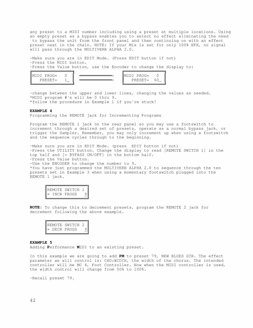
42
any preset to a MIDI number including using a preset at multiple locations. Usingan empty preset as a bypass enables you to select no effect eliminating the need to bypass the unit from the front panel and then continuing on with an effectpreset next in the chain. NOTE: If your Mix is set for only 100% EFX, no signalwill pass through the MULTIVERB ALPHA 2.0.
-Make sure you are in EDIT Mode. (Press EDIT button if not)-Press the MIDI button.-Press the Value button, use the Encoder to change the display to:ÅÁÁÁÁÁÁÁÁÁÁÁÁÁÁÁÁÈ ÅÁÁÁÁÁÁÁÁÁÁÁÁÁÁÁÁÈÂMIDI PROG= 0 Â ÁÁÁÁÁÁÁÁÁÁÁÁÁ> ÂMIDI PROG= 0 ÂÂ PRESET= 1_ Â ÁÁÁÁÁÁÁÁÁÁÁÁÁ> Â PRESET= 60_ ÂËÁÁÁÁÁÁÁÁÁÁÁÁÁÁÁÁÎ ËÁÁÁÁÁÁÁÁÁÁÁÁÁÁÁÁÎ
-change between the upper and lower lines, changing the values as needed.*MIDI program #'s will be 0 thru 9.*follow the procedure in Example 1 if you're stuck!
EXAMPLE 4Programming the REMOTE jack for Incrementing Programs
Program the REMOTE 1 jack on the rear panel so you may use a footswitch toincrement through a desired set of presets, operate as a normal bypass jack, ortrigger the Sampler. Remember, you may only increment up when using a footswitchand the sequence cycles through to the beginning.
-Make sure you are in EDIT Mode. (press EDIT button if not)-Press the UTILITY button. Change the display to read [REMOTE SWITCH 1] in thetop half and [= BYPASS ON/OFF] in the bottom half.-Press the Value button.-Use the ENCODER to change the number to 9.*You have just programmed the MULTIVERB ALPHA 2.0 to sequence through the tenpresets set in Example 3 when using a momentary footswitch plugged into theREMOTE 1 jack.
ÅÁÁÁÁÁÁÁÁÁÁÁÁÁÁÁÁÈÂREMOTE SWITCH 1 ÂÂ= INCR PROGS 9 ÂËÁÁÁÁÁÁÁÁÁÁÁÁÁÁÁÁÎ
NOTE: To change this to decrement presets, program the REMOTE 2 jack fordecrement following the above example.
ÅÁÁÁÁÁÁÁÁÁÁÁÁÁÁÁÁÈÂREMOTE SWITCH 2 ÂÂ= DECR PROGS 9 ÂËÁÁÁÁÁÁÁÁÁÁÁÁÁÁÁÁÎ
EXAMPLE 5Adding Performance MIDI to an existing preset.
In this example we are going to add PM to preset 79, NEW BLUES GTR. The effectparameter we will control is: CHO:WIDTH, the width of the chorus. The intendedcontroller will be MC 4, Foot Controller. Now when the MIDI controller is used,the width control will change from 50% to 100%.
-Recall preset 79.

43
-Press the EDIT button.-Press the Preset button and use the Encoder to select preset 120. -Press theStore button.*You've just copied #79 to location 120.-Press the ADD EFFECT and turn the Encoder until you see [ADD:MIDI CONTRL?].-Press the ENTER button.*You have just added a MIDI controller to the preset.-Press the Param button four times.-Press the Value button.-Use the Encoder to select [CHO:LEVEL = 100%]-Press the Value button again, DON'T CHANGE THIS VALUE.-Press the Value button again.-Use the Encoder to change the value to 50%.-Press the Value button one more time!!!!-DON"T CHANGE THE SETTING-Press the STORE button.*Press the EDIT Mode button to exit Edit Mode.
You now have edited a Factory Preset 79 for PM control of the chorus width. Whenyou use the left pedal on the X-15 your chorus level will change from 50% to100%. You may edit any existing preset to be controlled by PM. Remember to UNLOCKthe preset to STORE your changes and then re-lock the presets.
EXAMPLE 6Controlling the Overall Level of an ALPHA 2.0 Preset.
To control the level on each preset, you must add the two MIDI controllers set uplike this TO EACH PRESET and control the Dry and Efx parameters of the Mix withone foot controller.
We will use Factory Preset 79 again for this example. If you have completedExample 5, adding PM to a Factory Preset, copy Factory Preset 79 into location121.
-Recall preset 79.-Press the EDIT button.-Press the Preset button and use the Encoder to select preset 121.-Press the Store button.*You've just copied #79 to location 121.-Press the ADD EFFECT button and them turn the Encoder until you see [ADD:MIDICONTRL?].-Press the ENTER button.-Add another MIDI controller-Press the Param button eight times.-Press the Value button twice.-Use the Encoder to select [MC 11:EXP. CTRL.]-Press the Value button again, DON'T CHANGE THIS VALUE.-Press the Value button again, DON'T CHANGE THIS VALUE EITHER.-Press the Value button.-Use the Encoder to select [MIX:EFX = 75%]-Press the Value button once. .-Use the Encoder to select [MC 11:EXP. CTRL.]-Press the Value button again, DON'T CHANGE THIS VALUE.-Press the Value button again, DON'T CHANGE THE VALUE.-Press the Value button.-Press the STORE button.

44
Now, when the right pedal on the X-15 is used, the output volume of the ALPHA 2.0changes from 0 to 100%. You may change the amount of minimum and maximum levelthe foot pedal controls by setting the Low and High Values (3rd and 4th screen)when adding the MIDI controller.
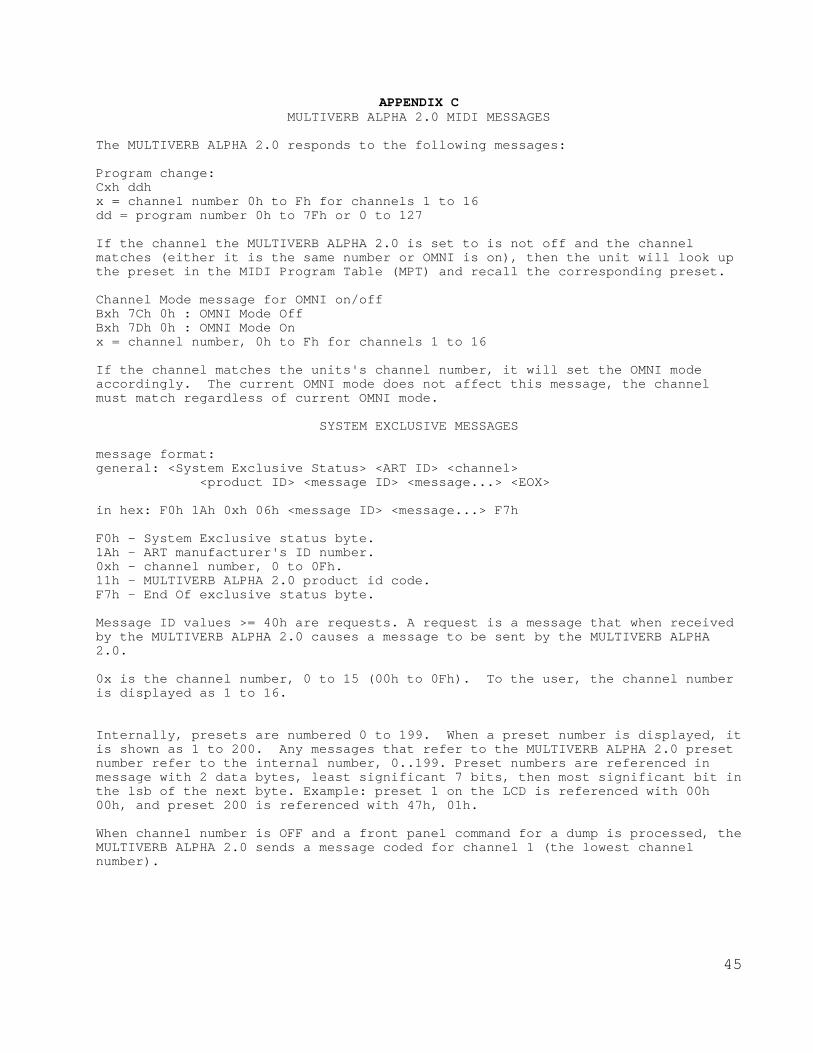
45
APPENDIX CMULTIVERB ALPHA 2.0 MIDI MESSAGES
The MULTIVERB ALPHA 2.0 responds to the following messages:
Program change:Cxh ddhx = channel number 0h to Fh for channels 1 to 16dd = program number 0h to 7Fh or 0 to 127
If the channel the MULTIVERB ALPHA 2.0 is set to is not off and the channelmatches (either it is the same number or OMNI is on), then the unit will look upthe preset in the MIDI Program Table (MPT) and recall the corresponding preset.
Channel Mode message for OMNI on/offBxh 7Ch 0h : OMNI Mode OffBxh 7Dh 0h : OMNI Mode Onx = channel number, 0h to Fh for channels 1 to 16
If the channel matches the units's channel number, it will set the OMNI modeaccordingly. The current OMNI mode does not affect this message, the channelmust match regardless of current OMNI mode.
SYSTEM EXCLUSIVE MESSAGES
message format:general: <System Exclusive Status> <ART ID> <channel> <product ID> <message ID> <message...> <EOX>
in hex: F0h 1Ah 0xh 06h <message ID> <message...> F7h
F0h - System Exclusive status byte.1Ah - ART manufacturer's ID number.0xh - channel number, 0 to 0Fh.11h - MULTIVERB ALPHA 2.0 product id code.F7h - End Of exclusive status byte.
Message ID values >= 40h are requests. A request is a message that when receivedby the MULTIVERB ALPHA 2.0 causes a message to be sent by the MULTIVERB ALPHA2.0.
0x is the channel number, 0 to 15 (00h to 0Fh). To the user, the channel numberis displayed as 1 to 16.
Internally, presets are numbered 0 to 199. When a preset number is displayed, itis shown as 1 to 200. Any messages that refer to the MULTIVERB ALPHA 2.0 presetnumber refer to the internal number, 0..199. Preset numbers are referenced inmessage with 2 data bytes, least significant 7 bits, then most significant bit inthe lsb of the next byte. Example: preset 1 on the LCD is referenced with 00h00h, and preset 200 is referenced with 47h, 01h.
When channel number is OFF and a front panel command for a dump is processed, theMULTIVERB ALPHA 2.0 sends a message coded for channel 1 (the lowest channelnumber).

46
DETAILED DESCRIPTION OF MESSAGES
Set Bypass OFF: F0 1A 0x 11 03 00 00 F7Set Bypass ON: F0 1A 0x 11 03 00 01 F7This allows remotely setting the state of BYPASS in the MULTIVERB ALPHA 2.0without affecting anything else in the unit.
Request DUMP all presets: F0 1A 0x 11 4B F7 LOAD all presets: F0 1A 0x 11 0B <many bytes> F7Dumps all presets in preset number order. No compression of the data is done.
Request MPT table: F0 1A 0x 11 4C F7Set MPT table: F0 1A 0x 11 0C <128 * 2 bytes> F7For each MIDI program number there is a corresponding MULTIVERB ALPHA 2.0 presetnumber. Each entry (internally) is 0..199 and is sent as 2 bytes. First theleast significant 7 bits, then the msb. This is done for each of the 128 MIDIprogram numbers.
When FX ON/OFF Enable is ON, you may use MIDI controller 84 to activate MIDIBypass.
If you find you require additional MIDI technical information, please contact orCustomer Service department at (716) 436-2720.

47
APPENDIX D MIDI Implementation ChartART MULTIVERB ALPHA 2.0 model 471; Date: JANUARY 1992; VER 2.0|--------------------------------------------------------------------|| Function | Transmitted | Recognized | Remarks ||--------------------|-------------|-------------|-------------------|| Basic Default | X | 1-16 | note 1 || Channel Channel | X | 1-16 | ||--------------------|-------------|-------------|-------------------|| Default | X | Mode 1,3 | note 1 || Mode Messages | X | OMNI ON/OFF | || Altered | X | O | ||--------------------|-------------|-------------|-------------------|| Note | X | O | || Number True Voice | X | O | ||--------------------|-------------|-------------|-------------------|| Velocity Note ON | X | O | || Note OFF | X | O | ||--------------------|-------------|-------------|-------------------|| After Key's | X | O | || Touch Ch's | X | O | ||--------------------|-------------|-------------|-------------------|| Pitch Bender | X | O | ||--------------------|-------------|-------------|-------------------|| | O | O | effects on/off || | | | controllers send || Control | | | controller msgs || | | | when presets are || Change | | | recalled || | | | || | | | || | | | ||--------------------|-------------|-------------|-------------------|| Prog | X | 0-127 |assignable to any || Change True # | X | |preset ||--------------------|-------------|-------------|-------------------|| System Exclusive | O | O |See: manual ||--------------------|-------------|-------------|-------------------|| System :Song Pos | X | X | || :Song Sel | X | X | || Common :tune | X | X | ||--------------------|-------------|-------------|-------------------|| System :Clock | X | X | || Real Time:Commands | X | X | ||--------------------|-------------|-------------|-------------------|| Aux :Local ON/OFF | X | X | || Mes- :All Notes Off | X | X | || sages:Active Sense | X | X | || :Reset | X | O | ||--------------------------------------------------------------------| Notes: 1: Factory default is channel 1, OMNI ON. Current setting is maintained in non-volatile RAM and does not change when the MULTIVERB ALPHA 2.0 is powered on. Mode 1: OMNI ON, POLY Mode 2: OMNI ON, MONO O: Yes Mode 3: OMNI OFF, POLY Mode 3: OMNI OFF, MONO X: No

48
APPENDIX EMIDI: CONTROLLERS & NUMBERS
CONTROLLER # CONTROLLER DESCRIPTION _0 UNDEFINED1 MOD WHEEL2 BREATH CONTROLLER3 UNDEFINED4 FOOT CONTROLLER5 PORTAMENTO TIME6 DATA ENTRY (msb)7 MAIN VOLUME8 BALANCE9 UNDEFINED10 PAN11 EXPRESSION CONTROLLER12-15 UNDEFINED16-19 GENERAL PURPOSE #'S 1-420-31 UNDEFINED32-63 LSB FOR VALUES 0-3164 DAMPER PEDAL (SUSTAIN)65 PORTAMENTO66 SOSTENUTO67 SOFT PEDAL68 UNDEFINED69 HOLD 270-79 UNDEFINED ( X-15 EFFECTS ON/OFF )80-83 GENERAL PURPOSE #'S 5-884-90 UNDEFINED *84 DEFAULT BYPASS91 EXTERNAL EFFECTS DEPTH92 TREMOLO DEPTH93 CHORUS DEPTH94 CELESTE (DETUNE) DEPTH95 PHASER DEPTH96 DATA INCREMENT97 DATA DECREMENT98 NON-REGISTERED PARAMETER # LSB99 NON-REGISTERED PARAMETER # MSB100 REGISTERED PARAMETER # LSB101 REGISTERED PARAMETER # MSB102-120 UNDEFINED121-127 RESERVED FOR CHANNEL MODE MESSAGES
CONTINUOUS CONTROLLERS:PITCH BEND WHEEL CHANNEL PRESSURE POLY AFTER TOUCHNOTE ON VELOCITY NOTE ON KEY # NOTE OFF VELOCITYNOTE OFF KEY #
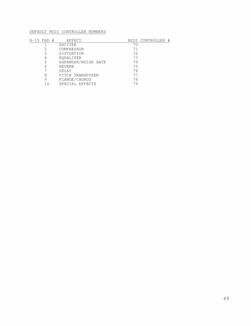
49
DEFAULT MIDI CONTROLLER NUMBERS
X-15 PAD # EFFECT MIDI CONTROLLER #1 EXCITER 702 COMPRESSOR 713 DISTORTION 724 EQUALIZER 735 EXPANDER/NOISE GATE 746 REVERB 757 DELAY 768 PITCH TRANSPOSER 779 FLANGE/CHORUS 7810 SPECIAL EFFECTS 79

50
APPENDIX FDIAGRAMS
INSTRUMENT INTO MULTIVERB ALPHA 2.0 INTO TWO AMPLIFIERS ¸¶¶¶¶¶¶¶¶¶¶¶¶¶¶¶¶¶¶¶¶¶¶¶¶¶¶¶¶¶¶¶¶¶¶¶¶¶¶¶¶¶¶¶¶¶¶¶¶¶¶¹ · MULTIVERB ALPHA 2.0 · · LINE IN LINE OUT · · LT LT RT · º¶¶¶¶¶¾¶¶¶¶¶¶¶¶¶¶¶¶¶¶¶¶¶¶¶¶¶¶¶¶¾¶¶¶¶¶¶¶¶¶¶¾¶¶¶¶¶¶¶¶» · · · · · · · · · ¸¶¶¶¶¶¿¶¶¶¶¶¹ ¸¶¶¶¿¶¶¶¹ ¸¶¶¶¿¶¶¶¹ ·INSTRUMENT · · AMP 1 · · AMP 2 · º¶¶¶¶¶¶¶¶¶¶¶» º¶¶¶¶¶¶¶» º¶¶¶¶¶¶¶»
GUITAR INTO MULTIVERB ALPHA 2.0 CONTROLLED BY ART X-15
¸¶¶¶¶¶¶¶¶¶¶¶¶¶¶¶¶¶¶¶¶¶¶¶¶¶¶¶¶¶¶¶¶¶¶¹ · ART X-15 · · · · IN OUT THRU · º¶¶¶¶¶¹¶¶¶¶¶¶¶¶¶¹¶¶¶¶¶¶¶¶¶¹¶¶¶¶¶¶¶¶» · · · · ¸¶¶¶¶¶¶¶¶¶¶¶¶¶¶¶¶¶¶¶¶¶¶¶¹ · º¶¶¶¶>¶¶¶¶· IN AUDIO · · · MIDI ALPHA 2.0 OUT ¼¶¶¶¶¶>¶¶¶¶¶¶¶¶ º¶¶¶¶¶¶¶¶¶¶¶¶¶¶<¶¶¶¶½ OUT IN · º¶¶¶¶¶¶¶¶¶¶¶¶¶¶¶¶¶¾¶¶¶¶¶» · · ¸¶¶¶¶¶¶¶¶¶¶¶¹ · · GUITAR ¼¶¶¶¶¶¶¶¶¶¶>¶¶¶¶¶¶¶¶¶¶¶¶¶¶¶¶¶¶¶¶» º¶¶¶¶¶¶¶¶¶¶¶»
STEREO EFFECTS SEND AND RETURN WITH MULTIVERB ALPHA 2.0 ¸¶¶¶¶¶¶¶¶¶¶¶¶¶¶¶¶¶¶¶¶¶¶¶¶¶¶¶¶¶¶¶¶¶¶¶¶¶¶¶¶¶¶¶¶¶¶¶¶¶¶¹ · ALPHA 2.0 · · LINE IN LINE OUT · · LT RT LT RT · º¶¶¶¶¶¾¶¶¶¶¶¶¶¾¶¶¶¶¶¶¶¶¶¶¶¶¶¶¶¶¾¶¶¶¶¶¶¶¶¶¶¾¶¶¶¶¶¶¶¶» · · · · · · · · · · · · ¸¶¶¶¶¶¿¶¶¶¶¶¶¶¿¶¶¶¶¶¶¶¶¶¶¶¶¶¶¶¶¿¶¶¶¶¶¶¶¶¶¶¿¶¶¶¶¶¶¶¶¹ · LT RT LT RT · · EFFECT SEND EFFECT RETURN · · OR OR · · AUX OUT INPUT CHANNEL #,# · · · · MIXER · º¶¶¶¶¶¶¶¶¶¶¶¶¶¶¶¶¶¶¶¶¶¶¶¶¶¶¶¶¶¶¶¶¶¶¶¶¶¶¶¶¶¶¶¶¶¶¶¶¶¶»

51
APPENDIX GUSING THE MULTIVERB ALPHA 2.0 WITH AN X-15 ULTRAFOOT
When an ART X-15 ULTRAFOOT is used with the ALPHA 2.0, remotecontrol of the parameters and the ability to turn on and off theeffects themselves greatly extend the capabilities of the ALPHA2.0. More than half of the ALPHA 2.0's factory presets are set upwith MIDI controllers providing you instant access to theparameters with your X-15.
You do not need to reprogram the X-15 ULTRAFOOT for use with theALPHA 2.0. All programming and setup is done with the ALPHA 2.0.Add a MIDI Controller to the ALPHA 2.0 preset and edit theparameters. The default settings allow for almost instantaneous usewith both devices. Refer to the example in Appendix B, AddingPerformance MIDI to an Existing Preset.
To correctly hook up the two devices, two MIDI cables should beused (see the hookup diagram on the preceding page). Both the ALPHA2.0 and X-15 "talk" to each other keeping their status' up to date.When the X-15 is in Effect Mode, it will display which effects inthe preset are active by lighting the associated pad's LED. If youadd, delete, or change the status of an effect with the ALPHA 2.0,the X-15 will monitor and display (or not display if you remove orturn off an effect) the change.
All of the presets in the ALPHA 2.0 with MIDI controllers assignedto them are set to be controlled by MIDI Controllers (MC) 4 and 11.On the X-15, the left expression controller is MC 4 and the rightpedal is MC 11. When adding a MIDI controller to a preset in theALPHA 2.0 the default value for the MIDI controller (screen 2,CONTROLLER IS) is MC 4, Foot Controller. To select another MIDIcontroller, use the Encoder to change the Value while editing thisscreen.
Every time a message is sent from the X-15 to the ALPHA 2.0, theAlpha's LCD displays the message sent. Effects on and off messagesand real time pedal values will be displayed, program changemessages (preset changes) will not be displayed. For effects on andoff messages to be displayed the X-15 must be in Effect Mode.Anytime either foot controller is moved, the ALPHA 2.0 displays theparameter name and value.
To control the output level of any ALPHA 2.0 preset, assign twoMIDI controllers to the preset, use one pedal as the controller,and control the Dry and Efx parameters of the Mix. See Example 6 inAppendix B for setting up a preset for level control.

52
ART MULTIVERB ALPHA 2.0 SPECIFICATIONS
Presets..................................................... 115
Memory Locations............................................. 90
Dynamic Range .....................................>90dB Typical
Equivalent Input Noise...................................-107dBv
Operating Level.......................................+16dBV max
Input Impedance...........................................1M ohm
Output Impedance..........................................1K ohm
Mechanical..................1.75"H X 19"W X 10"D, all steel case
Power Requirements.........105-125 Volts AC, 60Hz, Internal Fuse 140ma @ 117VAC, 16.4W(Export unit configured for destination country.)
MIDI Receive Channel.......................1-16, OMNI (all), OffMIDI Programs....................May be assigned to any Preset #Connections................Stereo In/Out 1/4" phone, MIDI IN, OUT, ................THRU, 2.1mm (+)9 VDC OUTPUT
ART retains a policy of constant product improvement.Specifications are subject to change without notice.
Designed and manufactured in the United States of America.
Applied Research & Technology, Inc.215 Tremont StreetRochester, New York 14608
(716) 436-2720(716) 436-3942 (FAX)http://www.artroch.com

53
MULTIVERB ALPHA 2.0 PRESET LIST
1 OPEN CHAMBER REV LPF REV-3 EQL AES 1 controller: 4
2 CARNEGIE HALL LPF R-DDL-S REV-3 EQL AES (no controllers)
3 HOTEL BALLROOM LPF REV-3 EQL AES (no controllers)
4 AMBIENT TALK REV REV-1 EQL (no controllers)
5 DIG.GUITAR TUNER TNR (no analog) (no controllers)
6 MULTI-SHIFTER S-DDL-S D-PTR (no analog) (no controllers)
7 ULTRAHARMONITAR D-PTR (no analog) (no controllers)
8 STUNNING PHASER PSR EQL (no controllers)
9 TERMINAYTOR S-DDL-L PSR EQL 4 controllers: 11 4
10 AMBIENT SPACE REV-3 EQL AES (no controllers)
11 BIG CONCERT REV LPF REV-3 EQL 2 controllers: 11 4
12 BRGHT VOCAL ROOM REV-2 EQL (no controllers)
13 SYMPHONY HALL LPF REV-3 EQL AES 1 controller: 4
14 GLISTENING PLATE LPF REV-3 EQL AES (no controllers)
15 VOICED DBL VERB LPF REV-3 EQL AES (no controllers)
16 VOCAL CHOIR REVB R-DDL-S REV-3
EQL AES (no controllers)
17 TIGHT VOICE VERB REV-3 EQL (no controllers)
18 VOCAL CLOSE ROOM T-DDL-S REV-1 EQL (no controllers)
19 VOCAL SHADOW DBL CHO GAT-1 EQL 2 controllers: 11 4
20 SAMPLE W/REVERB SMP-S REV-1 EQL 1 controller: 4
21 DEEP GATED SNARE GAT-3 EQL AES (no controllers)
22 BIG HAIR GATE GAT-2 EQL AES (no controllers)
23 CONCUSSION GATE R-DDL-S GAT-2 EQL (no controllers)
24 RAPID GATE REV R-DDL-S GAT-3 EQL (no controllers)
25 CONCERT 12 STRNG LPF PTR REV-1 EQL 2 controllers: 11 4
26 MELLOW 12 STRING PTR REV-1 EQL AES 2 controllers: 11 4
27 SPATIAL CHORUS LPF CHO TRM AES 3 controllers: 11 4
28 DOUBLE CANYONS S-DDL-S CHO PAN EQL 2 controllers: 11 4
29 SWEPT CHORUS S-DDL-L FLA EQL AES 2 controllers: 11 4
30 ASLEEP AT WHEEL T-DDL-S REV-2 EQL AES 2 controllers: 11 4
31 INFINITE CHORUS R-DDL-S REV-1 CHO EQL 2 controllers: 11 4
32 NITE DREAM FLANG R-DDL-S REV-1 FLA EQL 3 controllers: 11 4
33 CHORAL DREAM R-DDL-S REV-1 FLA EQL 2 controllers: 11 4
34 FIRE ON ICE FLA GAT-2 (no analog) 2 controllers: 11 4
35 ALIEN INVASION S-DDL-L FLA MPN EQL 3 controllers: 4 11
36 DIAMOND CUTTER R-DDL-L REV-1 FLA EQL 2 controllers: 11 4
37 ITS HAPPEN'N GTR LPF R-DDL-S REV-1 CHO AES 3 controllers: 11 4
38 RABBIT FOOD GTR REV-1 FLA TRM AES 2 controllers: 11 4
39 CHAMPAGNE CHORUS R-DDL-L GAT-1 TRM EQL 2 controllers: 11 4

54
40 WET BODY CHORUS REV-1 CHO TRM EQL 2 controllers: 11 4
41 GROOVY FLANGE FLA GAT-1 AES 3 controllers: 11 4
42 INFINITE DREAM R-DDL-S REV-1 CHO EQL 2 controllers: 11 4
43 WATCHTOWER REV-1 CHO EQL AES 3 controllers: 11 4
44 NIGHT VOYAGER R-DDL-S REV-1 FLA PAN EQL AES 2 controllers: 11 4
45 SHADOW TONIGHT CHO GAT-1 EQL AES 1 controller: 4
46 GHOST CHOIR S-DDL-S FLA EQL AES 2 controllers: 11 4
47 CARBIDE CUTTER FLA GAT-1 EQL AES 2 controllers: 11 4
48 SPACE PHOBIA REV-2 FLA TRM (no analog) 2 controllers: 11 4
49 GRIND TO DEATH T-DDL-S REV-2 EQL AES 2 controllers: 11 4
50 OCTAVE SWEEP X15 LPF PTR REV-1 EQL 2 controllers: 11
51 OCTAVE SWEEP DWN LPF PTR REV-1 EQL 1 controller: 11
52 PEDAL SWEEP 5TH LPF PTR REV-1 EQL 2 controllers: 4 11
53 PEDAL DELAY PAN S-DDL-L MPN EQL 1 controller: 11
54 X15 LO NOTE BEND PTR REV-1 (no analog) 1 controller: 11
55 X15 HI NOTE BEND PTR REV-1 (no analog) 1 controller: 11
56 RED ROCKS S-DDL-S EQL 2 controllers: 11 4
57 SLICK BASS GTR FLA PAN EQL 2 controllers: 11 4
58 FROG BASS GTR S-DDL-S CHO PAN AES 2 controllers: 11 4
59 SMOKEFILLED BASS REV-1 CHO EQL AES 2 controllers: 11 4
60 OMINOUS UNDRTONE R-DDL-L PTR (no analog) (no controllers)
61 ORIENTAL DREAMS R-DDL-S PTR (no analog) (no controllers)
62 PITCH MICRO SPIN LPF R-DDL-S PTR (no analog) 2 controllers: 11 4
63 WARPED STRINGS LPF R-DDL-L PTR (no analog) 1 controller: 4
64 HYPER FLANGE GTR R-DDL-S FLA AES 2 controllers: 11 4
65 BASSMENT THUNK REV-1 CHO EQL (no controllers)
66 TRAVERS TRY THIS S-DDL-L FLA TRM AES 2 controllers: 11 4
67 FLANGED ALIVE R-DDL-S FLA GAT-2 EQL 2 controllers: 11 4
68 DEEP DLY CHORUS S-DDL-S CHO EQL 2 controllers: 11 4
69 STRAT COUNTRY S-DDL-S CHO TRM EQL 2 controllers: 11 4
70 HOME-FUNKY GTR R-DDL-S GAT-2 TRM EQL 2 controllers: 11 4
71 FULL FAT RHYTHM REV-1 CHO PAN EQL AES 2 controllers: 11 4
72 OVERDOSE CHORUS S-DDL-S CHO PAN AES 2 controllers: 11 4
73 SWEEPING STRINGS S-DDL-S CHO EQL 2 controllers: 11 4
74 CLEAN DRUM VERB LPF REV-1 EQL AES (no controllers)
75 MEDIUM DRUM ROOM LPF REV-3 EQL AES (no controllers)
76 ROCK CONCERT KIT LPF REV-3 EQL AES (no controllers)
77 PERC DECAY R-DDL-S PTR EQL AES 1 controller: 4
78 TOMS IN THE HALL REV-3 EQL (no controllers)
79 NEW BLUES GTR REV-1 CHO EQL AES (no controllers)
80 PURPLE GATE LPF FLA GAT-2 EQL 2 controllers: 11 4
81 BOOM ROOM TOMB LPF REV-2 EQL AES (no controllers)
82 PHIL's TOMS! LPF R-DDL-S GAT-3 EQL AES (no controllers)
83 SNAREGATE REV LPF GAT-3 EQL AES (no controllers)
84 SPOKEN WORD LPF REV-1

55
EQL AES (no controllers)
85 VOCAL PLATE R-DDL-S REV-3 AES (no controllers)
86 WARM VOCAL ROOM REV-3 EQL AES (no controllers)
87 DOUBLE VOICE R-DDL-S PTR AES (no controllers)
88 CHORUS/DLY VOCAL CHO GAT-1 EQL AES (no controllers)
89 IN FLIGHT VOCAL LPF R-DDL-S REV-3 EQL AES (no controllers)
90 DEJA VU VOCAL GAT-3 EQL AES (no controllers)
91 CLOUD NINETEEN LPF R-DDL-S REV-3 EQL AES (no controllers)
92 BREATH OF OXYGEN LPF R-DDL-S REV-3 EQL AES (no controllers)
93 THE EVIL ONES R-DDL-S CHO (no analog) (no controllers)
94 120 BPM SLAP DLY T-DDL-S REV-2 EQL AES 1 controller: 4
95 HORN/SAX BALLAD T-DDL-S REV-2 EQL AES 3 controllers: 4 11
96 INYOURFACE KICK T-DDL-S REV-2 EQL AES (no controllers)
97 BOMBSCARE R-DDL-S PTR EQL AES 1 controller: 4
98 TUNNEL BOMB R-DDL-S PTR EQL AES (no controllers)
99 SKIN TIGHTHEAD LPF REV-2 EQL AES (no controllers)
100 <BLANK TITLE> (no digital) (no analog) (no controllers)
101 BIG RAP KICK LPF REV-1 EQL AES (no controllers)
102 COSMIC ARCHIVE R-DDL-S GAT-2 PAN EQL AES (no controllers)
103 VARISPEED LESLIE FLA TRM AES 2 controllers: 11 4
104 SYNTH STACCATO R-DDL-S CHO GAT-1 AES 1 controller: 4
105 CALISTO FLANGE S-DDL-L FLA EQL (no controllers)
106 CRY BABY? LPF EQL 8 controllers: 11
107 SPATIAL FLANGE FLA EQL AES 2 controllers: 11 4
108 NIGHT STALKER T-DDL-L REV-1 EQL AES 2 controllers: 11 4
109 GITARAE FUGANT S-DDL-S D-PTR (no analog) (no controllers)
110 PHASED AGAIN S-DDL-S PSR EQL 2 controllers: 11 4
111 SPINNING PHASE PSR MIDIPAN EQL 1 controller: 4
112 SHIMMERPHASE PSR TRM EQL 1 controller: 4
113 X-15 FOOT PHASE PSR EQL 2 controllers: 11 4
114 OLD ORANGE PSR EQL 1 controller: 4
115 ORIENTAL SWEEP D-PTR AES (no controllers)

56
How to Read the Preset Description
¸¶¶¶¶¶¶¶¶¶¶¶¶¶¶¶¶¶¶¶¶¶¶¶¶¶¹·40 WET BODY
CHORUS ·¶¶¶¶→¶ Title Line · REV-1 CHO
TRM ·¶¶¶¶→¶ Digital Effects Line· EQL
·¶¶¶¶¶→ Analog Effects Line· 2
controllers: 11 4 ·¶¶¶¶¶→ MIDI ControllerLine
º¶¶¶¶¶¶¶¶¶¶¶¶¶¶¶¶¶¶¶¶¶¶¶¶¶»
The first line of the preset descriptiontells you the name and location of eachFactory Preset on the first line. On thenext line, which digital effects presentin the preset are shown. Analog effectsused for the preset are listed on thethird line. How many and which MIDIcontrollers are listed on the last line.
Table of Effect Abbreviations:FIrst is the abbreviation found in thepreset list. Next is the actual effectalgorithm name. In brackets, how thealgorithm name is displayed in the LCD.For a description of the algorithms andparameters, refer to the section"Description of Algorithms".
AES = ACOUSTIC ENVIRONMENT SIMULATOR [ACU-ENV-SIM], [AES]CHO = CHORUS [CHORUS], [CHO]D-PTR = DUAL PITCH TRANSPOSER [DUAL PTr],[2PT]EQL = EQUALIZER (SEVEN BAND EQUALIZER)[EQUALIZER], [EQL]FLA = FLANGER [FLANGER], [FLA]GAT-1 = GATED REVERB-1 [GATE-VERB-1],[GAT]GAT-2 = GATED REVERB-2 [GATE-VERB-2],[GAT]GAT-3 = GATED REVERB-3 [GATE-VERB-3],[GAT]LPF = LOW PASS FILTER [LOW-PASS], [LPF]MPN = MIDI-PAN [MPN]PAN = PANNER [PANNER], [PAN]PSR = PHASER [PHASER], [PSR]PTR = PITCH TRANSPOSER [PITCH-TRANS],[PTr]R-DDL-S = REGEN-DDL-SHORT [REGEN-DDL-S],[DDL]R-DDL-L = REGEN-DDL-LONG [REGEN-DDL-L],[DDL]REV-1 = REVERB-1 [REVERB-1], [REV]REV-2 = REVERB-2 [REVERB-2], [REV]REV-3 = REVERB-3 [REVERB-3], [REV]S-DDL-S = STEREO-DDL-SHORT [STREO-DDL-S],[DDL]S-DDL-L = STEREO-DDL-LONG [STREO-DDL-L],[DDL]SMP-S = SAMPLER-SHORT [SAMPLER-S], [SMP]SMP-L = SAMPLER-LONG [SAMPLER-L], SMPSMP+PTR = SAMPLER+PITCH TRANSPOSER[SAMPLER+PTR], [SPT]T-DDL-S = TAPPED-DDL-SHORT [TAP'D-DDL-S],[DDL]T-DDL-L = TAPPED-DDL-LONG [TAP'D-DDL-L],[DDL]TNR = GUITAR TUNER [TUNER], [TNR]TRM = TREMOLO [TREMOLO], [TRM]
WARRANTY & SERVICE INFORMATION
LIMITED WARRANTYWarranty service for this unit will beprovided by Applied Research &Technology, Inc. in accordance with thefollowing warrant statement.
Applied Research & Technology, Inc.warrants to the original purchaser thatthis product and the componentsthereof, will be free from defects inworkmanship and materials for a periodof one year from the date of purchase.Applied Research & Technology, Inc.(ART) will, without charge, repair orreplace, at its option, defectiveproduct or component parts upon prepaiddelivery to the factory servicedepartment or authorized servicecenter, accompanied by proof ofpurchase date in the form of a validsales receipt.
EXCLUSIONS: This warranty does notapply in the event of misuse or abuseof the product or as a result ofunauthorized alterations or repairs.This warranty is void if the serialnumber is altered, defaced, or removed.
ART reserves the right to make changesin design or make additions to orimprovements upon this product withoutany obligation to install the same onproducts previously manufactured.
ART shall not be liable for anyconsequential damages, includingwithout limitation damages resultingfrom loss of use. Some states do notallow limitation of incidental orconsequential damages, so the abovelimitation or exclusion may not applyto you. This warranty gives youspecific rights and you may also haveother rights which vary from state tostate.
For units purchased outside The UnitedStates, service will be provided by anauthorized distributor of AppliedResearch & Technology, Inc.
SERVICEThe following information is providedfor the unlikely event your unitrequires service.
1) Be sure the unit is the cause of theproblem. Check to make sure the unithas power supplied, all cables areconnected correctly and the cablesthemselves are in working condition.2) If you find the unit to be at fault,write down a description of the problemincluding how and when the problemoccurs.3) Call the factory for a ReturnAuthorization (RA) number.4) Pack the unit in it's originalcarton or a reasonable substitute. Thepacking box is not recommended for ashipping carton. Put the packaged unitin another box for shipping. Print theRA number clearly under the address.5) Include with your unit: a returnshipping address (We cannot ship to aP.O. Box), a copy of your purchasereceipt, a daytime phone number, andthe description of the problem.6) Ship the unit to:
APPLIED RESEARCH & TECHNOLOGY, INC. 215 TREMONT STREET ROCHESTER, NY 14608 ATTN: REPAIR DEPARTMENT RA # ___________________7) Contact our customer servicedepartment at (716) 436-2720 for yourReturn Authorization number orquestions regarding repairs. CustomerService hours are 9:00 AM to 4:00 PMEastern Time, Monday through Friday.