Embed Size (px)
Citation preview

IN FOCUS: FUTURE OF BIOSENSORS - ARTICLE
Multivariate Analysis of ToF-SIMS Data from MulticomponentSystems: The Why, When, and How
Daniel J. Graham • David G. Castner
Received: 22 June 2012 / Accepted: 20 July 2012 / Published online: 15 August 2012
� The Author(s) 2012. This article is published with open access at Springerlink.com
Abstract The use of multivariate analysis (MVA)
methods in the processing of time-of-flight secondary ion
mass spectrometry (ToF-SIMS) data has become increas-
ingly more common. MVA presents a powerful set of tools
to aid the user in processing data from complex, multi-
component surfaces such as biological materials and bio-
sensors. When properly used, MVA can help the user
identify the major sources of differences within a sample or
between samples, determine where certain compounds
exist on a sample, or verify the presence of compounds that
have been engineered into the surface. Of all the MVA
methods, principal component analysis (PCA) is the most
commonly used and forms an excellent starting point for
the application of many of the other methods employed to
process ToF-SIMS data. Herein we discuss the application
of PCA and other MVA methods to multicomponent ToF-
SIMS data and provide guidelines on their application and
use.
1 Introduction
The emerging technologies for creating complex and spe-
cific engineered surface chemistry has increased the need
for surface analysis methods that can accurately charac-
terize and verify the actual surface chemistry [1]. This is
particularly challenging when one considers the complex-
ity of even simple surface modifications, and the trend
towards using multicomponent, patterned surface chemis-
try in a wide range of biomedical applications, including
biosensing. For example, an engineered surface may have a
linker molecule to tether a coating to the substrate, mole-
cules with binding groups for a specific analyte, and other
molecules to provide a non-fouling background to avoid
non-specific adsorption [2]. Each of these surface compo-
nents could have a similar chemical composition with
differences only in the structure or arrangement of the
chemical groups. To optimize the performance of biosen-
sors it is essential to minimize non-specific interactions via
a non-fouling background and to maximize the biological
activity of surface tethered probe molecule via control of
orientation, conformation, and density [3]. Though no one
technique can provide a complete characterization of such
a surface, time-of-flight secondary ion mass spectrometry
(ToF-SIMS) is one method that shows great promise due to
its molecular specificity, relatively high mass resolution,
and high sensitivity [4]. However, ToF-SIMS data from
even a set of simple homogenous surfaces can be very
complex.
Good introductions to ToF-SIMS can be found in the
literature [4–7]. ToF-SIMS is a mass spectrometry tech-
nique that probes the chemistry and structure of the outer
surface by impacting energetic primary ions onto a sample
and analyzing the secondary ions emitted from the surface.
There are a wide variety of primary ions used in ToF-SIMS
ranging from mono-atomic ions such as Ar?, Ga?, Cs?,
Au?, Bi?, to cluster ions such as Aun? (n = 1-3), Bin
?
(n = 1–5), SF5?, Arn
? (n * 500–10,000) and C60?. These
ions impact the surface with energies typically in the range
This article is part of the Topical Collection ‘‘In Focus: Future
of Biosensors’’.
D. J. Graham (&) � D. G. Castner
Departments of Bioengineering and Chemical Engineering,
National ESCA and Surface Analysis for Biomedical Problems,
University of Washington, Box 351653, Seattle,
WA 98195-1653, USA
e-mail: [email protected]
D. G. Castner
e-mail: [email protected]
123
Biointerphases (2012) 7:49
DOI 10.1007/s13758-012-0049-3
of 1–25 keV causing a collision cascade that results in the
emission of ions, neutrals and radicals. Only a small frac-
tion (typically 1 % or less) of the emitted material is ion-
ized. These ionized atoms, molecules, and molecular
fragments are extracted into a time-of-flight mass analyzer
where they are separated by mass and recorded in a mass
spectrum. ToF-SIMS is an ultra high vacuum technique
that requires the samples be analyzed in a dehydrated state,
but hydrated conditions can be simulated by placing sam-
ples in a frozen hydrated state. In spite of this limitation,
ToF-SIMS has been used successfully to analyze a wide
range of organic and biological samples including proteins
[8–15], lipids [16–19], cells [20–25], and tissues [26–30].
A typical ToF-SIMS spectrum can contain hundreds of
peaks, the intensity of which can vary due to the com-
position, structure, order, and orientation of the surface
species [31]. ToF-SIMS data are inherently multivariate
since the relative intensities of many of the peaks within a
given spectrum are related, due to the fact that they often
originate from the same surface species [32, 33]. The
challenge is to determine which peaks are related to each
other, and how they relate to the chemical differences
present on the surface. This problem is then exacerbated
by the fact that a given data set typically contains mul-
tiple spectra from multiple samples, which can result in a
large data matrix to be analyzed. This data overload is
even more prominent in ToF-SIMS imaging where a
single 256 9 256 pixel image contains 65536 spectra.
This complexity, combined with the enormous amount of
data produced in a ToF-SIMS experiment, has led to a
marked increase in the use of multivariate analysis
(MVA) methods in the processing of ToF-SIMS images
and spectra [33].
Table 1 presents a summary of ToF-SIMS studies that
have been carried out using at least one MVA method.
As seen in the table, MVA includes an alphabet soup of
methods that are designed to aid a researcher in reducing
large data sets to a manageable number of variables with
the aim of helping them understand and interpret the
data. These methods include, but are not limited to
principal components analysis (PCA), discriminant anal-
ysis (DA), partial least squares (PLS), multivariate curve
resolution (MCR), and maximum autocorrelation factors
(MAF).
These MVA methods are one of many tools available
that can aid in the interpretation of ToF-SIMS images and
spectra. These methods are statistically based, and to be
used properly require good experimental plans and con-
trols. MVA methods should not be treated as a black box.
These methods are a way for the analyst to summarize and
understand the large data sets generated by ToF-SIMS. The
use of MVA does not preclude the need for a sound
understanding of ToF-SIMS, or for using complementary
surface analysis methods in order to interpret the data and
understand the surfaces being analyzed.
In this short review we will propose guidelines for the
successful application of MVA to ToF-SIMS data, and
provide examples from the literature and our group on how
these methods have been successfully applied. Since it is
beyond the scope of this paper to discuss all MVA methods
we will mainly focus on PCA and its application to ToF-
SIMS data, though other methods will also be highlighted.
PCA forms the basis of many of the other MVA methods
and therefore provides a good entry point into the use of
MVA with ToF-SIMS data.
2 PCA
2.1 Overview
A brief summary of PCA will be provided below. Jackson
and Wold [34–36] have provided an excellent general
introduction to PCA, and other overviews of using MVA
with ToF-SIMS data can be found in the literature [32, 37–
39, 41].
Principal component analysis is a MVA method that
looks at the overall variance within a data set. Herein a data
set is defined as a matrix where the rows contain samples
and the columns contain variables. For ToF-SIMS data the
samples are spectra and the variables are measured inten-
sities of individual mass channels or integrated peak areas
from selected or binned regions. PCA is calculated from
the covariance matrix of this original data set [42, 43].
Geometrically, PCA is an axis rotation that aligns a new set
of axes, called principal components (PC), with the maxi-
mal directions of variance within a data set [35]. PCA
generates three new matrices containing the scores, the
loadings, and the residuals. The scores show the relation-
ship between the samples (spectra) and are a projection of
the original data points onto a given PC axis. The loadings
show which variables (peaks) are responsible for the sep-
aration seen in the scores plot. The loadings are the
direction cosines between the original axes and the new PC
axes. The residuals represent random noise that is pre-
sumed to not contain any useful information about the
samples [34].
Together the scores and loadings represent a concise
summary of the original data that in most cases can aid in
interpreting the data being analyzed. The scores and
loadings must be interpreted together and have little
meaning alone. Figure 1 shows the scores and loadings
plots from two brands of 70 % dark chocolate analyzed by
ToF-SIMS and PCA. The data was normalized to the total
intensity of each respective spectrum, square root trans-
formed and mean centered prior to PCA. As seen in Fig. 1a
Page 2 of 12 Biointerphases (2012) 7:49
123

Table 1 Summary table of selected studies using mva for processing of ToF-SIMS data
Samples/system MVA technique References
Multilayer surface grafting of furanones PCA [74]
Tissue analysis PCA [27, 28, 43]
Characterization of adsorbed proteins PCA [8, 9, 57–64, 75–77]
Analysis of SAMs on gold PCA [78–81]
Analysis of hydrogen and methane plasma modified graphite PCA [82]
Surface chemistry in mineral flotation separation PCA [83]
Analysis of lipids PCA [16–19]
Analysis of polymers PCA [84–91]
Quantification with polymers PCA [92–97]
Analysis of atmospheric aerosol particles PCA [98, 99]
PCA—data pretreatment, methodology PCA [32, 44, 45, 100]
Depth profiling PCA [101, 102]
Analysis of ball point pen ink PCA [103]
Analysis of sugars PCA [50, 104]
Image analysis of patterned surfaces PCA [67]
Discrimination between different calcium phosphate phases PCA [105]
Analysis of decellularized extra cellular matrix PCA [47, 48]
Analysis of the affects of storage on a new tooth cement PCA [106]
Determining the optimal plasma polymerization conditions for maleic anhydride PCA [107]
Discrimination between bacterial samples PCA [25]
Transfer of organics onto glass PCA [108]
Characterization of extracellular matrix secreted from cells PCA [13–15, 109]
Analysis of non-mass selected ToF-SIMS data MCR [110]
Forensic analysis of bioagents MCR [111]
MCR for image analysis MCR [112]
Depth profile analysis MCR [113]
Analysis of white radish sprouts MCR [114]
3D image analysis MCR [115]
Study of the mechanism of n-pentanol polymerization on SiO2 during rubbing MCR [116]
Analysis of mixed composition surfaces MCR [117]
Predicting wettability on patterned ITO surfaces PLS [118]
Predicting the surface composition of oxygen containing plasma polymers PLS [119]
Correlation of polymer surface chemistry with protein adsorption and/or cell growth PLS [44, 52, 120, 121]
Quantification of the composition of plasma polymerized thin films PLS [122]
Quantification of cross-linker density in polymer films PLS [123]
Quantification of protein adsorption on polymer surface PLS [56]
Identification and imaging of 15 N labeled cells MAF [124]
Analysis of proteins on samples with topography MAF [125]
Protein adsorption on dental materials DPCA [126]
Interpretation of SIMS depth profiles FA [127]
Imaging proteins on dialysis membranes Information theory [128]
Analysis of cells K-means [129]
Classification of adsorbed proteins NN [53]
Using mixture models for image analysis Mixture models [130]
Quantification of polymer blend composition PCA, PLS [131]
Analysis of monolayers on scribed silicon PCA, PLS [132]
Analysis of polymer microarrays PCA, PLS [49]
Characterization of PLL–PEG monolayers PCA, PLS [133]
Biointerphases (2012) 7:49 Page 3 of 12
123

the two samples are separated on the PC1 axis. The PC1
loadings in Fig. 1b show which peaks are responsible for
the differences seen between the two samples. In general
peaks with high loadings on one side of a given PC axis
will show a higher relative intensity for samples with high
scores on the same side of the given PC axis. In the case of
these two chocolates, Sample 2 (negative PC1 scores)
corresponds with a series of hydrocarbons and peaks such
as Al, Na, Ca (negative PC1 loadings). Sample 1 (positive
PC1 scores) corresponds with K and a series of higher mass
peaks from lipids and diacylglycerols (positive PC1 load-
ings). It should be noted that this does not necessarily mean
that the high mass lipid peaks do not show up in the spectra
from Sample 2, only that the relative intensities of these
peaks were lower in Sample 2. This can be seen in Fig. 2
which shows the relative intensity of Na and a peak from a
diacylglycerol of stearic and oleic acid. As expected, the
relative intensity of the Na peak is higher for Sample 1, and
the relative intensity of the diacylglycerol peak is higher
for Sample 2.
2.2 Data Collection
Since all MVA methods are statistically based, it is
important to make sure that one collects sufficient data to
have statistically relevant results. The exact number of
replicates required will depend on the system being ana-
lyzed. However, doing MVA processing on data from only
1 or 2 spots per sample will most likely produce mean-
ingless, unreproducible results unless the surfaces being
analyzed are extremely homogeneous. For ToF-SIMS
spectra we suggest collecting data from at least 3–5 spots
Table 1 continued
Samples/system MVA technique References
Discrimination between different paint surfaces PCA, PLS [134]
Determining distribution of polymers in blended polymer film PCA, MCR [135]
Analysis strategies for ToF-SIMS images with topography PCA, MCR [38]
Analysis strategies for mixed organic surfaces PCA, MCR [39]
Classification of bacterial strains PC-DFA [73, 136]
Classification of cells PC-DFA [20]
Identification of adsorbed proteins PCA, LDA [54, 55, 137, 138]
Correlation of images from different techniques using MVA PCA, CCA [139]
Impact of surface chemistry on chalcopyrite floatation PCA, DA [140]
Identification of cells in co-cultures PCA, PLS-DA [21]
Mapping lipids in mice PCA, HC [26]
Discrimination between different polymers PCA, NN [141]
Image denoising, segmentation and compound identification PCA, Latent profile Analysis [142]
Analysis strategies for ToF-SIMS images PCA, MAF [37, 143]
Analysis of ToF-SIMS images with topography PCA, Mixture model [144]
Comparing MAF with standard statistical tools for image analysis MAF, Statistics [145]
Analysis of bacterial isolates PC-CVA, GA-CVA [23]
Analysis of exhaled particles PCA, OPLS-DA [146]
ToF-SIMS image analysis strategies, Data Storage PCA, PARAFAC [147]
Exploratory analysis of biological surfaces PCA, PC-DFA, MAF [24]
Identification of adsorbed proteins PCA, LDA, DPCA [148]
Imaging of organic and biological systems PCA, MAF, MCR [149]
Characterization of carbohydrate microarrays PCA, MCR, PLS [51]
Strategies for analysis of biomolecules PCA, PCR, MAF [150]
Discrimination between bacterial samples PCA, PLS, LDA [151]
Discrimination between solid-phase extraction stationary phases PCA, PLS, NN [152, 153]
Analysis of Cu–Fe Sulfides PCA, SIMCA, K-NN [154]
Quantification of multicomponent protein mixtures PLS, SIMCA [10–12, 155]
Correlation of images from different techniques using MVA PLS, MAF [156]
Characterization of polymer blend PCA, MAF, MCR, PLS, PCR [157]
Classification of biological samples PCA, LDA, PLSDA, SIMCA [158]
Page 4 of 12 Biointerphases (2012) 7:49
123

per sample across at least 2 samples for homogenous sur-
faces, and 5–7 spots per sample across at least 3 samples
for non-homogenous samples. It is also best to collect data
from samples created on separate days to get a true mea-
sure of the sample-to-sample variability. Care should also
be taken to minimize, and ideally avoid, detector saturation
during data collection. Saturated peaks can result in the
production of extra factors that describe the non-linear
intensity variations of saturated peaks. For example, Lee
and Gilmore [40] showed an imaging PCA example of an
immiscible blend of PC/PVC where the first PC captured
the difference between the two polymers, and the second
PC captured differences between the 35Cl- peak due to
detector saturation. We have also observed isotopes load-
ing in opposite directions when one of the isotopic peaks is
saturated.
2.3 Data Preprocessing
2.3.1 Peak Selection
Though it is possible to run MVA on every mass channel of
a ToF-SIMS spectrum, it is more common for users to
export a set of selected peak areas from the spectrum. This
is a logical choice since ToF-SIMS spectra contain many
mass channels that contain only noise, or no counts, due to
the low background between peaks. Since the set of peaks
used in MVA can affect the results, peak selection becomes
the first data preprocessing step before one can run MVA.
Peak selection can be done by binning the data into chosen
Fig. 1 PCA scores and loadings from a set of dark chocolate
samples. a PCA PC1 scores. The black squares represent the 95 %
confidence limits for each sample. Samples are separated from each
other on the PC1 axis. b PCA PC1 loadings plot. Peaks with positive
loadings correspond with samples with positive scores. Peaks with
negative loadings correspond with samples with negative scores
Fig. 2 Peak area plots from the chocolate data. a m/z = 23 (Na), a
negative loading peak. b m/z = 605 (diacylglyerol peak), a positive
loading peak. As expected from the PCA results, the relative intensity
of Na is higher on sample 1 and the relative intensity of the
diacylglycerol peak is higher on sample 2
Biointerphases (2012) 7:49 Page 5 of 12
123

interval sizes, using automated peak detection routines, or
by manually choosing and measuring peak areas. Due to
the large number of peaks typically seen at each nominal
mass in ToF-SIMS spectra from organic and biological
surfaces, manual peak selection is recommended. Data
binning is quick, but it loses the high mass resolution
information present in the original spectra. If data binning
is used, one must go back to the original data to determine
which peaks are changing at a given mass to properly
interpret the MVA results. Automated peak selection rou-
tines are getting better, but they often misplace peak inte-
gration limits, which can be problematic when working
with spectra with overlapping peaks. Manual peak selec-
tion is time consuming, but allows the user to utilize all of
the spectral peaks and to check the peak integration limits
to assure they are placed properly across all samples. The
assumptions made when selecting peaks for ToF-SIMS
MVA have been reviewed previously [33].
Before selecting peaks it is important to make sure that
all of the spectra are properly mass calibrated, and that the
same calibration set is used for all spectra within a given
sample set. When selecting peaks it is recommended that
one overlaps representative spectra from each sample type
in a given set to be sure all peaks across all spectra are
selected. The same peak list must be used for all samples
within a given set.
2.3.2 Data Scaling
The results produced by many MVA methods depend
strongly on the data matrix preprocessing. Data prepro-
cessing includes normalization, mean centering, scaling
and transformation. The goal of data preprocessing is to
remove variance from the matrix that is not due to chem-
ical differences between the samples. This could include
variation due to the instrumentation, differences in the
absolute intensity of peaks within a spectrum, differences
due to topography or other factors. The assumptions made
when preprocessing a data matrix have been addressed
[33]. Normalization is done by dividing each variable
(peak) in the matrix by a scalar value. Normalization is
done to remove variance in the data that is due to differ-
ences such as sample charging, instrumental conditions or
topography. It should be noted however that normalization
can accentuate noise in ToF-SIMS images due to the low
count rates often found within the data. Therefore, care
should be taken when using normalization of ToF-SIMS
images. Mean centering subtracts the mean of each vari-
able (peak) from the data set. This allows the data to be
compared across a common mean of zero. Scaling refers to
dividing each variable by a constant, and transformation
refers to transforming the data with a function such as the
logarithm or square root. There are many different ways to
scale and transform a data set. It is recommended that one
selects a scaling and transformation method based on the
experimental uncertainty of each peak. ToF-SIMS data
often follows a Poisson distribution. Keenan and Kotula
[39, 44, 45] proposed a scaling method that accounts for
Poisson noise which has been found to work well for ToF-
SIMS data. If Poisson scaling is not available in the soft-
ware package being used, other good alternatives include
using a square root transform of the data or scaling by the
square root of the mean of the data. Regardless of the
preprocessing methods used, one should understand the
assumptions made [33] when applying a given method and
choose a method based on what they are trying to learn
from the data and not what gives the best looking results.
2.4 Interpreting Results
Once the data set has been processed using MVA the user
must interpret what, if anything, the results mean. This is
particularly important when using scale dependent methods
such as PCA or MCR since the results obtained will be
affected by the assumptions made when preprocessing the
data. Though there are no quantitative measures of the
validity for a given result, we suggest using the following
guidelines when examining the results from MVA pro-
cessed ToF-SIMS data: (1) Are the results logical? (2) Do
the results agree with the other data collected on the
samples? (3) Are the results reflected in the original data?
Multivariate analysis is simply a tool available to help
understand large data sets. As with any results, one should
always ask if the results obtained make sense. When using
MVA one should also ask if the assumptions made during
data pre-processing make sense, and are based off of valid
assumptions about the data. Also, since no one surface
analytical method can provide all the information needed to
understand a surface, it is important to collect comple-
mentary data on the samples within a given set. The user
can then validate the ToF-SIMS data with respect to the
information obtained from the other methods. Another
important aspect of interpreting results from MVA is to
validate the results by looking at the original data. This
means going back to look at the relative intensity of the
peaks that are highlighted in the loadings plots to verify
that they follow the trends shown in the scores plots (for
example, see Ref. [46]). This is particularly important
when using PCA since some PCs can capture multiple
trends across the samples. When this happens, one will find
that some peaks with high loadings can reflect changes in
only a subset of the samples seen in the scores plot. Once
caveat that should be noted when validating results with the
original data is that methods such as PCA are calculated
from the scaled covariance matrix, and that each sub-
sequent PC is calculated from the matrix after the previous
Page 6 of 12 Biointerphases (2012) 7:49
123

PCs have been subtracted from the data set. Therefore, the
original data is only truly reflective of the first PC.
Another important aspect to keep in mind is that unsu-
pervised MVA methods such as PCA are designed to find
the greatest directions of variance within a data set
regardless of their source. That means that if one sample
within a data set is contaminated, the first few PCs will
most likely separate out the contaminated sample from the
other samples. Thus, any variance that is due to the
designed surface chemistry may be suppressed by the large
variance due to the contamination. However, it is important
to note that being able to discover contamination within a
sample set can be a valuable piece of information that can
help troubleshoot sample preparation and handling proto-
cols. This information can then be fed back into the sample
procedures and experimental design so differences in the
surface chemistry of interest can be studied.
3 MVA of Complex Surfaces
Most biological materials are multicomponent whether
they involve a mixture of proteins, a combination of cells
and extracellular matrix, or a mixed polymer system used
as a scaffold for tissue engineering. Being able to accu-
rately characterize these samples can be challenging and
can push the limits of any analytical technique. ToF-SIMS
and MVA have been used to analyze a range of different
multicomponent systems including binary [8–11], ternary
[10] and multicomponent protein layers [12–15], lipids
[16–19], mammalian cells [20–22], microbial cells [23–
25], decellularized extracellular matrix [47, 48], tissues
[26–30] and polymer microarrays [49–52].
Many multicomponent systems are challenging to ana-
lyze because the components within the systems generate
the same peaks. For example, when analyzing immobilized
proteins with ToF-SIMS the spectra are dominated by
amino acid fragments, not small or large peptides. This
means that for any given protein, the ‘‘characteristic’’ peaks
will all be the same, and it is the relative intensities of these
peaks that encodes information about the proteins identity
[53–55], concentration [10–12, 56, 57], conformation [58–
62] orientation [63–66], or spatial distribution [66–69].
Therefore, these types of problems are truly multivariate in
nature. As a result of this interrelated spectral complexity,
one will need proper controls to be able to define the best
system to characterize a given sample set. Furthermore,
one will need to choose the appropriate MV method to
provide the information sought in the experiments. For
example PCA, MCR or MAF would be logical choices for
general data exploration or sample identification, whereas
PCR or PLS would be better for quantification or modeling,
and DFA, HCA or PLS-DA would be better for
classification. The remainder of this section provides a brief
discussion for applying MVA to multicomponent systems.
3.1 Analysis of Polymer Microarrays
Publications from Alexander et al. [49, 51, 52, 70, 71]
show how to combine combinatorial chemistry, ToF-SIMS
and MVA. They use a microarray printer to prepare
microarrays of a library of polymeric materials for high
throughput assays, and relate polymer functionality to
surface properties [49] and cellular interactions [52]. They
have also studied carbohydrate microarrays [51] and
examined printing heterogeneities with different polymer
formulations [70].
In their study of the relationship of surface chemistry
with wettability, the authors used a combinatorial copoly-
mer array of 576 different polymers from 24 unique
monomers [49]. The polymers were made using a 70:30
mixture of 2 monomers. PCA scores of the mean centered
data showed that most of the polymers clustered together
based off the major component of the monomer mixture.
The loadings showed peak trends that corresponded with
the chemical differences between the types of monomers as
expected from their molecular structures. The authors then
created a PLS model correlating the ToF-SIMS data with
the water contact angle, and showed good correlation
between the predicted and measured water contact angle
(R2 = 0.94). This work is a good demonstration of how
using a systematically designed study combined with ToF-
SIMS and MVA can provide useful chemical information
from a complex data set.
3.2 Analysis of Patterned NHS on Polymer Substrates
We have used ToF-SIMS imaging and PCA to analyze
patterned polymers surfaces functionalized with N-
hydroxysuccinimide (NHS) [67, 68]. For this, commer-
cially available slides with a PEG based coating were
patterned using standard photolithography methods. The
surfaces were imaged using ToF-SIMS and the images
were analyzed using PCA of the normalized, mean cen-
tered data. PC1 was able to separate the NHS from the
methoxy regions with good fidelity matching the originally
designed pattern. The loadings separating the two regions
were seen to contain peaks characteristic of the two com-
pounds. Interestingly PC3 showed a dark outline around
the border between the two regions. From the PC3 loadings
it was determined that these dark regions corresponded
with the photoresist material used in the pattern creation.
The presence of residual photoresist had not been previ-
ously reported in other studies using a similar patterning
method. This study presents a good example of how the
combination of PCA with ToF-SIMS data can often pick
Biointerphases (2012) 7:49 Page 7 of 12
123
up trends or identify components from complex data sets
that would otherwise be overlooked by the analyst. The
ability to identify the presence of submonolayer quantities
of unexpected organic contaminants on an organic surface
is particularly challenging, but as this study shows the
combination of ToF-SIMS and PCA is well suited for this
type of challenging analysis.
3.3 Analysis of DNA Microarray Spots
Our group has been working on a project analyzing spots
on DNA microarrays. In this project, DNA spots are
printed onto polymer-coated commercial microarray slides
(Slide H, amine-reactive polymer-coated slides, Schott
Nexterion, Louisville, USA). The exact chemistry of the
slides is proprietary, but it is known that the slides contain
NHS and a non-fouling background, most likely based on
polyethylene glycol (PEG). It is likely that the organic
coating is attached to the glass substrate via a silane linker.
The aim of this work is to investigate and understand the
surface chemistry of DNA microarrays with the goal of
improving their reproducibility and efficiency.
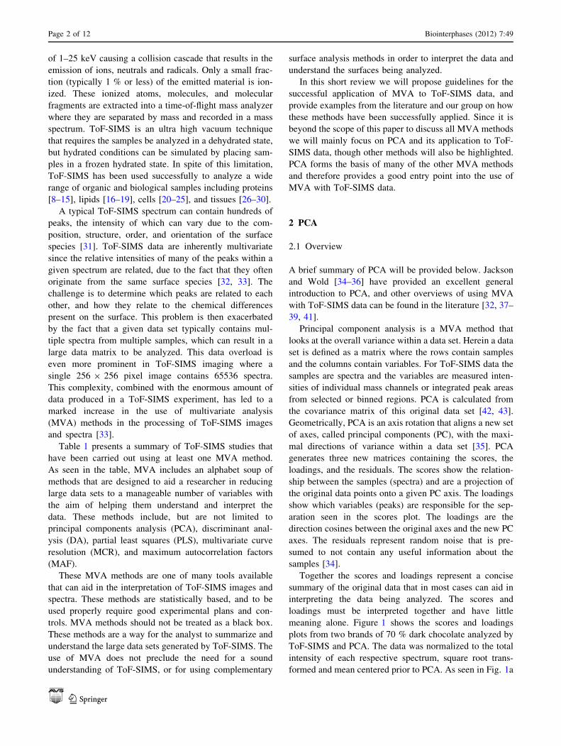
Figures 3 and 4 show the PCA scores and loadings plots
for the first 2 PCs from the negative ion data of a DNA spot
on the NHS coated slide. The data was Poisson scaled [45]
and then mean centered prior to PCA. As seen in Fig. 3a,
PC1 separates the DNA spot from the slide background.
The PC1 loadings seen in Fig. 3b show that the DNA spot
(darker area in PC1 scores plot, negative loadings) corre-
sponds with a series of nitrogen containing peaks, as well
as the PO2 and PO3 peaks from the DNA. The areas with
Fig. 3 PC1 scores and loadings from a DNA spot on an NHS
functionalized slide. a PC1 scores image. b PC1 loadings. The brightareas correspond with peaks of the form CxHyOz. The dark regionscorrespond with nitrogen containing peaks as well as PO2 and PO3
peaks from the DNA
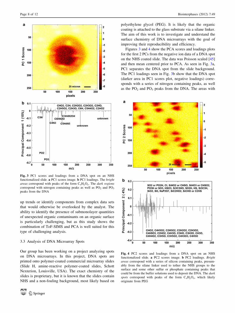
Fig. 4 PC2 scores and loadings from a DNA spot on an NHS
functionalized slide. a PC2 scores image. b PC2 loadings. Brightareas correspond with a series of silicon containing peaks, presum-
ably from the silane linker used to tether the NHS groups to the
surface and some other sulfur or phosphate containing peaks that
could be from the buffer solutions used to deposit the DNA. The darkspots correspond with peaks of the form CxHyOz, which likely
originate from PEG
Page 8 of 12 Biointerphases (2012) 7:49
123

positive scores on PC1 (bright area) correspond with a
series of peaks of the form CxHyOz, many of which are
characteristic of PEG. Examining the PC1 scores image
closely, it is apparent there are several bright spots scat-
tered around the surface. These spots are even more clearly
highlighted in the PC2 scores plot (see Fig. 4a). As seen in
the PC2 loadings plot these spots correspond with a set of
CxHyOz peaks (darker area in PC2 scores plot, negative
loadings), once again many of which are characteristic of
PEG. Looking at this data set as a whole, one can see that
DNA was spotted successfully onto the NHS coated slide,
however the DNA spot is not very uniform as noted by the
variation in intensity of the spot in the PC1 scores plot.
Overall, the background around the spot is fairly uniform,
but it appears there are spots that could be agglomerations
of PEG scattered across the surface (as seen by the bright
regions in the PC1 scores image and the dark regions in the
PC2 scores image). The non-uniform nature of PEG coat-
ings has been observed previously [72].
In this example, PCA was able to quickly summarize the
data from a sample with a complex and heterogeneous
surface chemistry, and highlight non-uniformities in the
DNA spots and in the background coating chemistry. This
type of information can then be fed back into the surface
engineering design to improve the sample preparation
methods to prepare more uniform DNA spots with
improved sensitivity and reproducibility.
3.4 Discriminating Cell and Tissue Types
Several groups have explored using MVA and ToF-SIMS
to distinguish cells [20–25, 73] and tissues [26–30]. Bio-
logical samples such as these represent some of the most
complex samples being explored by ToF-SIMS.
Fletcher et al. [73] used principal component discrimi-
nant function analysis (PC-DFA) to process the spectra of
nineteen bacterial strains of bacteria common to urinary
tract infections. PC-DFA applies discriminant function
analysis to the results from PCA and enables classification
of samples by maximizing the between group differences
while minimizing the within group differences. In their
study they showed that they could discriminate between 15
different strains with minimal overlap between sample
groups. They also showed using a sub group of the data that
they could build a PC-DFA model that could be used to
correctly classify spectra from various bacterial strains.
Wu et al. [27, 30] has explored the use of ToF-SIMS and
MVA for the analysis of tissues. In one example they used
PCA to analyze six different tissues from a mouse embryo
(brain, spinal cord, heart, liver, rib, skull) [30]. For this
analysis spectra were extracted from images taken from the
various tissues and processed with PCA. When using all
tissue types in the analysis they were able to show
separation between most groups, though they saw some
overlap between the brain and spinal cord, and the heart
and liver tissues. As could be expected, the brain and spinal
cord tissues clustered near each other, as these were similar
tissue types. The skull and rib tissues were also seen on the
same side of the PC axes as could be expected since they
are both bony tissues.
These brief examples show that MVA has proven suc-
cessful for distinguishing and classifying various cell and
tissue types, but the analysis is still limited by the lack of
identified peaks that appear within their spectra. It is also
noted that in most cases, the spectra from cells and tissues
are dominated by low mass fragments that can come from
multiple sources including proteins, lipids and other com-
pounds in the samples. This lack of higher mass molecular
information makes the use of MVA even more critical
since it can be used to distinguish trends in the fragmen-
tation pattern within a set of spectra that can be specific to
the type of sample [32, 55].
4 Outlook and Conclusions
As the use of MVA with ToF-SIMS data increases, it is
important that users understand the methods used and
assumptions made when processing their data. Proper
experimental design and sampling statistics are required to
ensure the results acquired are statistically significant. The
choice of MVA method should also be considered
according to the goals of the analysis and the results
obtained should be verified by going back to the raw data.
It should be remembered that MVA methods are simply
a set of tools that can be used by the analyst to better
understand their data. MVA does not replace the need to
understand the basic methodologies of analyzing ToF-
SIMS data, rather they provide a way to explore the data
more efficiently and make use of all of the information
within a given data set. MVA methods reduce large data
sets down to a more manageable set of variables that can
highlight trends in the data, build predictive models, and
find differences between samples. The continued devel-
opment and use of MVA methods for ToF-SIMS data
processing holds great promise for understanding complex
surface chemistry and dealing with the large data sets
generated from both simple and complex sample sets.
However, there is still a great need to expand the avail-
ability and depth of peak libraries for ToF-SIMS so one can
interpret the results gained through applying MVA. This is
particularly true for biological samples and other complex
surfaces such as biosensors.
Acknowledgments The authors gratefully acknowledge the funding
and facilities provided by the National ESCA and Surface Analysis
Biointerphases (2012) 7:49 Page 9 of 12
123

Center for Biomedical Problems (NESAC/BIO) through grant EB-
002027 from the National Institutes of Health. The authors would also
like to thank Dr. Nicolas Vandencasteele and Dr. Lara Gamble for
providing the DNA microarray data. The authors also gratefully
acknowledge NIH grant EB-001473 for funding for the DNA project.
Open Access This article is distributed under the terms of the
Creative Commons Attribution License which permits any use, dis-
tribution, and reproduction in any medium, provided the original
author(s) and the source are credited.
References
1. Castner DG, Ratner BD (2002) Surf Sci 500(1–3):28–60
2. Harbers GM, Emoto K, Greef C, Metzger SW, Woodward HN,
Mascali JJ, Grainger DW, Lochhead MJ (2007) Chem Mater
19(18):4405–4414. doi:10.1021/070509
3. Wu P, Castner DG, Grainger DW (2008) J Biomat Sci-Polym E
19(6):725–753
4. Belu AM, Graham DJ, Castner DG (2003) Biomaterials
24(21):3635–3653. doi:10.1016/0142-9612(03)00159-5
5. Vickerman JC (2009) In: Vickerman JC, Gilmore IS (eds)
Surface analysis—the principal techniques (2nd edn). John
Wiley & Sons, Chichester, p. 113–203
6. Vickerman JC, Briggs D (2001) ToF-SIMS: surface analysis by
mass spectrometry. IM Publications, Chichester
7. Benninghoven A (1994) Surf Sci 299(300):246–260
8. Bruning C, Hellweg S, Dambach S, Lipinsky D, Arlinghaus HF
(2006) Surf Interface Anal 38(4):191–193
9. Wald J, Muller C, Wahl M, Hoth-Hannig W, Hannig M, Kop-
narski M, Ziegler C (2010) Phys Status Solidi 207(4):831–836
10. Wagner MS, Shen M, Horbett TA, Castner DG (2003) Appl Surf
Sci 203–204:704–709
11. Wagner MS, Shen M, Horbett TA, Castner DG (2003) J Biomed
Mater Res A 64(1):1–11
12. Wagner MS, Horbett TA, Castner DG (2003) Biomaterials
24(11):1897–1908
13. Canavan HE, Graham DJ, Cheng XH, Ratner BD, Castner DG
(2007) Langmuir 23(1):50–56
14. Canavan HE, Cheng XH, Graham DJ, Ratner BD, Castner DG
(2005) J Biomed Mater Res A 75A(1):1–13
15. Canavan HE, Cheng XH, Graham DJ, Ratner BD, Castner DG
(2005) Langmuir 21(5):1949–1955
16. Biesinger MC, Miller DJ, Harbottle RR, Possmayer F, McIntyre
NS, Petersen NO (2006) Appl Surf Sci 252(19):6957–6965
17. Anderton CR, Vaezian B, Lou K, Frisz JF, Kraft ML (2012) Surf
Interface Anal 44(3):322–333
18. McArthur SL, Halter MW, Vogel V, Castner DG (2003)
Langmuir 19(20):8316–8324
19. Vaezian B, Anderton CR, Kraft ML (2010) Anal Chem
82(24):10006–10014
20. Baker MJ, Gazi E, Brown MD, Clarke NW, Vickerman JC,
Lockyer NP (2008) Appl Surf Sci 255(4):1084–1087
21. Barnes CA, Brison J, Robinson M, Graham DJ, Castner DG,
Ratner BD (2012) Anal Chem 84(2):893–900
22. Kulp KS, Berman ESF, Knize MG, Shattuck DL, Nelson EJ, Wu
L, Montgomery JL, Felton JS, Wu KJ (2006) Anal Chem
78:3651–3658
23. Vaidyanathan S, Fletcher JS, Jarvis RM, Henderson A, Lockyer
NP, Goodacre R, Vickerman JC (2009) Analyst
134(11):2352–2360
24. Vaidyanathan S, Fletcher JS, Henderson A, Lockyer NP,
Vickerman JC (2008) Appl Surf Sci 255(4):1599–1602
25. Ingram JC, Bauer WF, Lehman RM, O’Connell SP, Shaw AD
(2003) J Microbiol Methods 53(3):295–307
26. Brulet M, Seyer A, Edelman A, Brunelle A, Fritsch J, Ollero M,
Laprevote O (2010) J Lipid Res 51(10):3034–3045
27. Wu L, Felton JS, Wu KJJ (2010) Method Mol Biol 656:267–281
28. Mains J, Wilson C, Urquhart A (2011) Eur J Pharm Biopharm
79(2):328–333
29. Amaya KR, Sweedler JV, Clayton DF (2011) J Neurochem
118(4):499–511
30. Wu L, Lu X, Kulp KS, Knize MG, Berman ESF, Nelson EJ,
Felton JS, Wu KJJ (2007) Int J Mass Spec 260:137–145
31. Michel R, Castner DG (2006) Surf Interface Anal
38(11):1386–1392. doi:10.1002/2382
32. Graham DJ, Wagner MS, Castner DG (2006) Appl Surf Sci
252(19):6860–6868
33. Wagner MS, Graham DJ, Ratner BD, Castner DG (2004) Surf
Sci 570(1–2):78–97
34. Wold S, Esbensen K, Geladi P (1987) Chemom Intell Lab Sys
2(1–3):37–52
35. Jackson JE (1980) J Qual Technol 12:201–213
36. Jackson JE (1991) A Users’s guide to principal components.
John Wiley & Sons, Inc., New York
37. Tyler BJ, Rayal G, Castner DG (2007) Biomaterials
28(15):2412–2423
38. Lee JLS, Gilmore IS, Fletcher IW, Seah MP (2009) Surf
Interface Anal 41(8):653–665
39. Lee JLS, Gilmore IS, Seah MP (2008) Surf Interface Anal
40(4):1–14
40. Lee JLS, Gilmore IS (2009) In: Vickerman JC, Gilmore IS (eds)
Surface analysis—the principal techniques, 2nd edn. John Wiley
& Sons, Chichester, pp 563–611
41. Jasieniak M, Graham DJ, Kingshott P, Gamble L, Griesser H
(2009) In: Riviere J, Myhra S (eds) Handbook of surface and
interface analysis. CRC Press, p. 529–564
42. Mellinger M (1987) Chemom Intell Lab Sys 2:29–36
43. Beebe KR, Kowalski BR (1987) Anal Chem 59(17):1007A–
1017A
44. Keenan MR, Smentkowski VS, Ohlhausen JA, Kotula PG
(2008) Surf Interface Anal 40(2):97–106
45. Keenan MR, Kotula PG (2004) Surf Interface Anal
36(3):203–212
46. Cheng F, Gamble LJ, Grainger DW, Castner DG (2007) Anal
Chem 79:8781–8788
47. Barnes CA, Brison J, Michel R, Brown BN, Castner DG, Bad-
ylak SF, Ratner BD (2011) Biomaterials 32(1):137–143
48. Brown BN, Barnes CA, Kasick RT, Michel R, Gilbert TW,
Beer-Stolz D, Castner DG, Ratner BD, Badylak SF (2010)
Biomaterials 31(3):428–437
49. Urquhart AJ, Taylor M, Anderson DG, Langer R, Davies MC,
Alexander MR (2008) Anal Chem 80(1):135–142
50. Bolles KM, Cheng F, Burk-Rafel J, Dubey M, Ratner DM
(2010) Materials 3(7):3948–3964
51. Scurr DJ, Horlacher T, Oberli MA, Werz DB, Kroeck L, Bufali
S, Seeberger PH, Shard AG, Alexander MR (2010) Langmuir
26(22):17143–17155
52. Yang J, Mei Y, Hook AL, Taylor M, Urquhart AJ, Bogatyrev
SR, Langer R, Anderson DG, Davies MC, Alexander MR (2010)
Biomaterials 31(34):8827–8838
53. Sanni OD, Wagner MS, Briggs D, Castner DG, Vickerman JC
(2002) Surf Interface Anal 33(9):715–728
54. Lhoest JB, Wagner MS, Tidwell CD, Castner DG (2001) J
Biomed Mat Res 57(3):432–440
55. Wagner MS, Castner DG (2001) Langmuir 17(15):4649–4660
56. Ferrari S, Ratner BD (2000) Surf Interface Anal 29(12):837–844
57. Wagner MS, McArthur SL, Shen M, Horbett TA, Castner DG
(2002) J Biomat Sci Poly Ed 13(4):407–428
Page 10 of 12 Biointerphases (2012) 7:49
123

58. Kempson IM, Martin AL, Denman JA, French PW, Prestidge
CA, Barnes TJ (2010) Langmuir 26(14):12075–12080
59. Henry M, Dupont-Gillain C, Bertrand P (2003) Langmuir
19(15):6271–6276
60. Xia N, Castner DG (2003) J Biomed Mater Res A
67(1):179–190
61. Xia N, May CJ, McArthur SL, Castner DG (2002) Langmuir
18(10):4090–4097
62. Mouhib T, Delcorte A, Poleunis C, Henry M, Bertrand P (2010)
Surf Interface Anal 42(6–7):641–644
63. Park J-W, Cho I-H, Moon DW, Paek S-H, Lee TG (2011) Surf
Interface Anal 43(1–2):285–289
64. Baugh L, Weidner T, Baio JE, Nguyen P-CT, Gamble LJ,
Stayton PS, Castner DG (2010) Langmuir 26(21):16434–16441
65. Wang H, Castner DG, Ratner BD, Jiang SY (2004) Langmuir
20(5):1877–1887. doi:10.1021/035376
66. Liu F, Dubey M, Takahashi H, Castner DG, Grainger DW
(2010) Anal Chem 82(7):2947–2958. doi:10.1021/902964
67. Dubey M, Emoto K, Cheng F, Gamble LJ, Takahashi H, Gra-
inger DW, Castner DG (2009) Surf Interface Anal 41(8):645–652
68. Takahashi H, Emoto K, Dubey M, Castner DG, Grainger DW
(2008) Adv Func Mater 18:2079
69. Dubey M, Emoto K, Takahashi H, Castner DG, Grainger DW
(2009) Adv Func Mater 19:3046–3055
70. Scoutaris N, Hook AL, Gellert PR, Roberts CJ, Alexander MR,
Scurr DJ (2012) J Mater Sci Mater Med 23:385–391
71. Urquhart A, Anderson DG, Taylor GP, Alexander MR, Langer
R, Davies MC (2007) Adv Mater 19:2486–2491
72. Veiseh M, Wickes BT, Castner DG, Zhang M (2004) Bioma-
terials 25:3315–3324
73. Fletcher JS, Henderson A, Jarvis RM, Lockyer NP, Vickerman
JC, Goodacre R (2006) Appl Surf Sci 252(19):6869–6874
74. Al-Bataineh SA, Jasieniak M, Britcher LG, Griesser HJ (2008)
Anal Chem 80:430–436
75. Schilke KF, McGuire J (2011) J Coll Int Sci 358(1):14–24
76. Cheng XH, Canavan HE, Graham DJ, Castner DG, Ratner BD
(2006) Biointerphases 1(1):61–72
77. Michel R, Pasche S, Textor M, Castner DG (2005) Langmuir
21:12327–12332
78. Tuccitto N, Giamblanco N, Marletta G, Licciardello A (2008)
Appl Surf Sci 255(4):1075–1078
79. Auditore A, Tuccitto N, Quici S, Marzanni G, Puntoriero F,
Campagna S, Licciardello A (2004) Appl Surf Sci
231–232:314–317
80. Graham DJ, Price DD, Ratner BD (2002) Langmuir
18(5):1518–1527
81. Graham DJ, Ratner BD (2002) Langmuir 18(15):5861–5868
82. Deslandes A, Jasieniak M, Ionescu M, Shapter JG, Fairman C,
Gooding JJ, Hibbert DB, Quinton JS (2009) Surf Interface Anal
41(3):216–224
83. Hart B, Biesinger M, Smart RSC (2006) Miner Eng
19(6–8):790–798
84. von Gradowski M, Jacoby B, Hilgers H, Barz J, Wahl M,
Kopnarski M (2005) Surf Coat Tech 200(1–4):334–340
85. Lau Y-TR, Weng L-T, Ng K-M, Chan C-M (2010) Anal Chem
82(7):2661–2667
86. Mishra G, Easton CD, McArthur SL (2009) Langmuir
26(5):3720–3730
87. McArthur SL, Wagner MS, Hartley PG, McLean KM, Griesser
HJ, Castner DG (2002) Surf Interface Anal 33(12):924–931
88. Awaja F, Gilbert M, Kelly G, Fox B, Brynolf R, Pigram PJ
(2010) ACS Appl Mater Interfaces 2(5):1505–1513
89. Sarra-Bournet C, Poulin S, Piyakis K, Turgeon S, Laroche G
(2010) Surf Interface Anal 42(2):102–109
90. Medard N, Poleunis C, Eynde XV, Bertrand P (2002) Surf
Interface Anal 34(1):565–569
91. Lau Y-TR, Weng L-T, Ng K-M, Chan C-M (2011) Surf Inter-
face Anal 43(1–2):340–343
92. Vanden-Eynde X, Bertrand P (1997) Surf Interface Anal
25:878–888
93. Coullerez G, Lundmark S, Malmstrom E, Hult A, Mathieu HJ
(2003) Surf Interface Anal 35(8):693–708
94. Medard N, Benninghoven A, Rading D, Licciardello A, Audi-
tore A, Duc TM, Montigaud H, Vernerey F, Poleunis C, Ber-
trand P (2003) Appl Surf Sci 203–204:571–574
95. Coullerez G, Leonard D, Lundmark S, Mathieu HJ (2000) Surf
Interface Anal 29(7):431–443
96. Eynde XV, Bertrand P (1998) Surf Interface Anal
26(8):579–589
97. Coullerez G, Lundmark S, Malkoch M, Magnusson H, Malm-
strom E, Hult A, Mathieu HJ (2003) Appl Surf Sci 203–204:620
98. Peterson RE, Tyler BJ (2002) Atmos Environ 36:39–40
99. Peterson RE, Tyler BJ (2002) Atmos Environ
36(39–40):6041–6049
100. Wickes BT, Kim Y, Castner DG (2003) Surf Interface Anal
35(8):640–648
101. Michaeleen LP (2004) Appl Surf Sci 231–232:235–239
102. Mahoney CM, Kushmerick JG, Steffens KL (2010) J Phys Chem
C 114(34):14510–14519
103. Denman JA, Skinner WM, Kirkbride KP, Kempson IM (2010)
Appl Surf Sci 256(7):2155–2163
104. Berman ESF, Kulp KS, Knize MG, Wu LG, Nelson EJ, Nelson
DO, Wu KJ (2006) Anal Chem 78(18):6497–6503105. Lu HB, Campbell CT, Graham DJ, Ratner BD (2000) Anal
Chem 72(13):2886–2894
106. Torrisi A, Torrisi V, Tuccitto N, Gandolfi MG, Prati C, Licc-
iardello A (2010) Int J Mass Spec 289(2–3):150–161
107. Mishra G, McArthur SL (2010) Langmuir 26(12):9645–9658
108. Sano N, Abel M-L, Watts JF (2011) Surf Interface Anal
43(1–2):423–426
109. Canavan HE, Cheng XH, Graham DJ, Ratner BD, Castner DG
(2006) Plasma Process Polym 3(6–7):516–523
110. Smentkowski VS, Ostrowski SG, Kollmer F, Schnieders A,
Keenan MR, Ohlhausen JA, Kotula PG (2008) Surf Interface
Anal 40(8):1176–1182
111. Brewer LN, Ohlhausen JA, Kotula PG, Michael JR (2008)
Forensic Sci Int 179(2–3):98–106
112. Gallagher NB, Shaver JM, Martin EB, Morris J, Wise BM,
Windig W (2004) Chemom Intell Lab Sys 73(1):105–117
113. Lloyd KG (2007) J Vac Sci Technol A 25(4):878–885
114. Aoyagi S, Kuroda K, Takama R, Fukushima K, Kayano I,
Mochizuki S, Yano A (2012) Surf Interface Anal. doi:
10.1002/4893
115. Smentkowski VS, Ostrowski SG, Braunstein E, Keenan MR,
Ohlhausen JA, Kotula PG (2007) Anal Chem 79(20):7719–7726
116. Barnette AL, Asay DB, Ohlhausen JA, Dugger MT, Kim SH
(2010) Langmuir 26(21):16299–16304
117. Kargacin ME, Kowalski BR (1986) Anal Chem
58(11):2300–2306
118. Yang L, Shard AG, Lee JLS, Ray S (2010) Surf Interface Anal
42(6–7):911–915
119. Chilkoti A, Ratner BD, Briggs D (1993) Anal Chem
65:1736–1736
120. Perez-Luna VH, Horbett TA, Ratner BD (1994) J Biomed Mat
Res 28 (10):1111–1126
121. Chilkoti A, Schmierer AE, Perez-Luna VH, Ratner BD (1995)
Anal Chem 67(17):2883–2891
122. Chilkoti A, Ratner BD, Briggs D (1992) In: Proceedings of the
International Conference on Secondary Ion Mass Spectrometry.
John Wiley & Sons, Chichester, UK, p. 815-818
123. Belu A, Perez-Luna VH, Ratner BD, Heller J (1996) Quantita-
tive ToF-SIMS Studies of Cross-Linked Poly(Methly
Biointerphases (2012) 7:49 Page 11 of 12
123

Methacrylate) Using Multivariate Statistical Methods. ACS
Polym Preprints 37:841–841
124. Tyler BJ, Takeno MM, Hauch KD (2011) Surf Interface Anal
43(1–2):336–339
125. Tyler B, Bruening C, Rangaranjan S, Arlinghaus H (2011)
Biointerphases 6(3):135–141
126. Bernsmann F, Lawrence N, Hannig M, Ziegler C, Gnaser H
(2008) Anal Bioanal Chem 391(2):545–554
127. Splinter SJ, Heide PAWvd, Lin A, McIntyre NS (1995) Surf
Interface Anal 23 (9):573–580
128. Aoyagi S, Kudo M, Hayama M, Hasegawa U, Sakai K, Tozu M,
Hoshi T (2003) e-J Surf Sci Nanotech 1:67–71
129. Szakal C, Narayan K, Fu J, Lefman J, Subramaniam S (2011)
Anal Chem 83(4):1207–1213
130. Willse A, Tyler B (2002) Anal Chem 74(24):6314–6322
131. Cossement D, Gouttebaron R, Cornet V, Viville P, Hecq M,
Lazzaroni R (2006) Appl Surf Sci 252(19):6636–6639
132. Yang L, Lua Y–Y, Jiang G, Tyler BJ, Linford MR (2005) Anal
Chem 77(14):4654–4661
133. Wagner MS, Pasche S, Castner DG, Textor M (2004) Anal
Chem 76(5):1483–1492
134. Gresham GL, Groenewold GS, Bauer WF, Ingram JC (2000) J
Forensic Sci 45(2):310–323
135. Miyasaka T, Ikemoto T, Kohno T (2008) Appl Surf Sci
255(4):1576–1579
136. Thompson CE, Ellis J, Fletcher JS, Goodacre R, Henderson A,
Lockyer NP, Vickerman JC (2006) Appl Surf Sci
252(19):6719–6722
137. Lhoest JB, Wagner MS, Castner DG (1999) In: Proceedings of
the 12th International Conference on Secondary Ion Mass
Spectrometry (SIMS 12). Elsevier Science, Amsterdam
p. 935–938
138. Wagner MS, Castner DG (2003) Appl Surf Sci 203–204:
698–703
139. Eijkel GB, Kukrer Kaletas B, van der Wiel IM, Kros JM, Luider
TM, Heeren RMA (2009) Surf Interface Anal 41(8):675–685
140. Brito e Abreu S, Skinner W (2011) Miner Eng 24(2):160–168
141. Sanni OD, Henderson A, Briggs D, Vickerman JC (1999) In:
Secondary Ion Mass Spectrometry, SIMS XII, Proceedings of
the International Conference on Secondary Ion Mass Spec-
trometry. Elsevier Science, Brussels, p. 805–808
142. Tyler B (2003) Appl Surf Sci 203–204:825–831
143. Henderson A, Fletcher JS, Vickerman JC (2009) Surf Interface
Anal 41(8):666–674
144. Rangarajan S, Tyler BJ (2004) Appl Surf Sci 231–232:406–410
145. Keenan MR, Smentkowski VS (2011) Surf Interface Anal
43(13):1616–1626
146. Almstrand AC, Josefson M, Bredberg A, Lausmaa J, Sjovall P,
Larsson P, Olin AC (2012) Eur Resp J 39(1):59–66
147. Klerk LA, Broersen A, Fletcher IW, van Liere R, Heeren RMA
(2007) Int J Mass Spec 260(2–3):222–236
148. Wagner MS, Tyler BJ, Castner DG (2002) Anal Chem
74(8):1824–1835
149. Tyler BJ (2006) Appl Surf Sci 252(19):6875–6882
150. Park J-W, Min H, Kim Y-P, Kyong Shon H, Kim J, Moon DW,
Lee TG (2009) Surf Interface Anal 41(8):694–703
151. Tyler BJ, Willse A, Shi H, Peterson RE (1999) In: Proceedings
of the International Conference on Secondary Ion Mass Spec-
trometry. John Wiley & Sons, Chichester, p. 943–946
152. Nord LI, Jacobsson SP (1998) Chemom Intell Lab Sys
44(1–2):153–160
153. Ohrlund A, Hjertson L, Jacobsson SP (1997) Surf Interface Anal
25(2):105–110
154. Kalegowda Y, Harmer SL (2012) Anal Chem 84:2754–60
155. Wagner MS, Horbett TA, Castner DG (2003) Langmuir
19(5):1708–1715
156. Lloyd KG, Walls DJ, Wyre JP (2009) Surf Interface Anal
41(8):686–693
157. Kono T, Iwase E, Kanamori Y (2008) Appl Surf Sci
255(4):997–1000
158. Berman ESF, Wu L, Fortson SL, Kulp KS, Nelson DO, Wu KJ
(2009) Surf Interface Anal 41(2):97–104
Page 12 of 12 Biointerphases (2012) 7:49
123


![Paul Ahern - Time of Flight Secondary Ion Mass Spectroscopy [ToF-SIMS] theory & practice](https://img.pdfslide.us/doc/110x75/55504121b4c905b2788b4981/paul-ahern-time-of-flight-secondary-ion-mass-spectroscopy-tof-sims-theory-practice.jpg)