Embed Size (px)
Citation preview
3016 IEEE TRANSACTIONS ON INDUSTRIAL ELECTRONICS, VOL. 58, NO. 7, JULY 2011
Multivariable-PI-Based dq Current Control ofVoltage Source Converters With Superior Axis
Decoupling CapabilityBehrooz Bahrani, Student Member, IEEE, Stephan Kenzelmann, Student Member, IEEE, and
Alfred Rufer, Fellow, IEEE
Abstract—This paper presents a linear direct–quadrature cur-rent control strategy for voltage source converters (VSCs) in arotating reference frame (RRF). The described method is basedon multivariable-proportional–integral (PI) regulators and pro-vides fast dynamics and a zero steady-state error. Contrary tothe well-known conventional PI-based control strategies in RRFs,the presented method provides practically decoupled axes with asuperior disturbance rejection capability. Moreover, its implemen-tation is relatively simple and does not impose excessive structuralcomplexity compared to its conventional PI-based competitors.The method is applicable to both single- and three-phase systemsand also to anisotropic three-phase systems, e.g., synchronousmotors with different direct and quadrature impedances driven byVSCs. Implementing a three-phase test system, the performance ofthe presented method is experimentally evaluated.
Index Terms—Current control, multivariable-proportional–integral (PI) controllers, stationary and rotating reference frames,vector control, voltage source converters (VSCs).
I. INTRODUCTION
POWER inverters with regulated input currents are widelyutilized in many grid-tied applications, e.g., distributed
power generation with renewable energy resources such asphotovoltaic energy [2], [3] and wind energy [4], HVdc applica-tions [5], active power filters [6]–[8], power factor controllers[9], [10], etc. Recently, the high depth of penetration of dis-tributed energy resources has also intensified the demand forsuch inverters. In most of such applications, a voltage sourceconverter (VSC) is interfaced to the utility grid through a linereactor filter, and a current regulation scheme is adopted by theVSC to control its input current while the dc link voltage isregulated by a relatively slower control loop compared to thatof the current [11].
Over the years, considerable research has been conducted onthe current regulation of VSCs, and various approaches havebeen proposed [12]–[23]. Generally, these approaches can becategorized into two major classes: 1) linear and 2) nonlinear
Manuscript received November 19, 2009; revised April 23, 2010 and July 16,2010; accepted July 31, 2010. Date of publication August 30, 2010; date ofcurrent version June 15, 2011.
The authors are with the Laboratoire dÉlectronique Industrielle, EcolePolytechnique Fédérale de Lausanne, 1015 Lausanne, Switzerland (e-mail:[email protected]; [email protected]; [email protected]).
Color versions of one or more of the figures in this paper are available onlineat http://ieeexplore.ieee.org.
Digital Object Identifier 10.1109/TIE.2010.2070776
controllers [12]. Nonlinear approaches [13], [14] normally im-pose structural complexity but do not offer impressive and supe-rior performance compared to that of linear schemes. However,the structural simplicity and fully digital implementability oflinear control strategies, specifically stationary reference frame(SRF)- and rotating reference frame (RRF)-based controllers,have made them so popular. Among the SRF controllers, thesimple and linear proportional–integral (PI) controllers areconsidered as the most conventional approach. However, dueto their well-known drawbacks, e.g., a nonzero steady-state er-ror, other approaches such as SRF-based proportional–resonant(PR) [16]–[18] controllers have been proposed, which trackac references in the stationary frame with a zero steady-stateerror. The PR approach is based on providing an infinite gainat the target frequency for eliminating the steady-state error atthat frequency, which is virtually similar to the infinite gain ofa PI controller at dc. Although the PR approach is relativelysimple and easy to implement for both single- and three-phaseapplications, however, it suffers from several drawbacks, e.g.,sensitivity to grid frequency variations, exponentially decayingtransients during step changes, and being pushed toward insta-bility margins even by a small phase shift introduced by theadopted current sensors [16].
Among the RRF controllers, the PI regulators are the mostwell-known and easy-to-implement approaches which providea satisfactory performance, i.e., fast dynamics and a zerosteady-state error. The PI-based current regulation approachis originally proposed in [15] and is extensively studied andadopted for the current control of both single- and three-phase systems in various applications [2], [3], [5], [9]–[12],[15], [24]–[32]. In an RRF, usually referred to as a dq frame,ac (time varying) quantities appear as direct and quadrature(d and q) dc (time invariant) quantities allowing the controller tobe designed as dc–dc converters presenting an infinite controlgain at the steady-state operating point for a zero steady-stateerror. In the proposed control strategy of [15], two distinctcurrent axes, i.e., d and q axes, are identified, which are aimedto be independently regulated. However, due to the structureof the PI-based controller, the d and q axes are not fullydecoupled, and each axis acts as a disturbance for the other one.Since PI controllers inherently have poor disturbance rejectioncapabilities, step changes in one axis generate transients in theother one, which might last even several cycles and leads topower quality and performance degradation.
0278-0046/$26.00 © 2010 IEEE
Downloaded from http://www.elearnica.ir
BAHRANI et al.: MULTIVARIABLE-PI-BASED dq CURRENT CONTROL OF VSCs 3017
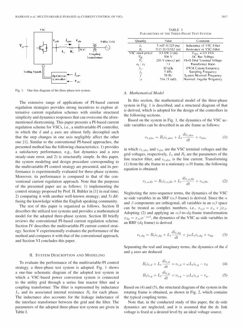
Fig. 1. One-line diagram of the three-phase test system.
The extensive range of applications of PI-based currentregulation strategies provides strong incentives to explore al-ternative current regulation schemes with similar structuralsimplicity and dynamics responses that can overcome the afore-mentioned shortcoming. This paper presents a PI-based currentregulation scheme for VSCs, i.e., a multivariable-PI controller,in which the d and q axes are almost fully decoupled suchthat the step changes in one axis negligibly affect the otherone [1]. Similar to the conventional PI-based approaches, thepresented method has the following characteristics: 1) providesa satisfactory performance, e.g., fast dynamics and a zerosteady-state error, and 2) is structurally simple. In this paper,the system modeling and design procedure corresponding tothe multivariable-PI control strategy are presented, and its per-formance is experimentally evaluated for three-phase systems.Moreover, its performance is compared to that of the con-ventional current regulation approach. Note that the purposesof the presented paper are as follows: 1) implementing thecontrol strategy proposed by Prof. H. Bühler in [1] in real time;2) comparing it with another well-known strategy; and 3) dif-fusing the knowledge within the English speaking community.
The rest of this paper is organized as follows. Section IIdescribes the utilized test systems and provides a mathematicalmodel for the adopted three-phase system. Section III brieflyreviews the conventional PI-based current regulation scheme.Section IV describes the multivariable-PI current control strat-egy. Section V experimentally evaluates the performance of themethod and compares it with that of the conventional approach,and Section VI concludes this paper.
II. SYSTEM DESCRIPTION AND MODELING
To evaluate the performance of the multivariable-PI controlstrategy, a three-phase test system is adopted. Fig. 1 showsa one-line schematic diagram of the adopted test system inwhich a VSC-based power conversion system is connectedto the utility grid through a series line reactor filter and acoupling transformer. The filter is represented by inductanceLt and its associated internal resistance Rt for each phase.The inductance also accounts for the leakage inductance ofthe interface transformer between the grid and the filter. Theparameters of the adopted three-phase test system are given inTable I.
TABLE IPARAMETERS OF THE THREE-PHASE TEST SYSTEM
A. Mathematical Model
In this section, the mathematical model of the three-phasesystem in Fig. 1 is described, and a structural diagram of thatis derived, which is adopted for the design of the controllers inthe following sections.
Based on the system in Fig. 1, the dynamics of the VSC ac-side variables can be described in an abc frame as follows:
vt,abc = Rtit,abc + Ltdit,abc
dt+ vabc (1)
in which vt,abc and vabc are the VSC terminal voltages and thegrid voltages, respectively, Lt and Rt are the parameters of theline reactor filter, and it,abc is the line current. Transforming(1) from the abc frame to a stationary αβ0 frame, the followingequation is obtained:
vt,αβ0 = Rtit,αβ0 + Ltdit,αβ0
dt+ vαβ0. (2)
Neglecting the zero-sequence terms, the dynamics of the VSCac-side variables in an SRF (αβ frame) is derived. Since the αand β components are orthogonal, all variables in an αβ spacecan be treated as complex numbers, i.e., xαβ = xα + jxβ .Adopting (2) and applying an αβ-to-dq-frame transformationxdq = xαβe−jωt, the dynamics of the VSC ac-side variables inan RRF (dq frame) is derived
vt,dq = Rtit,dq + Ltdit,dq
dt+ jωLtit,dq + vdq. (3)
Separating the real and imaginary terms, the dynamics of the dand q axes are deduced
Rtit,d + Ltdit,ddt
= vt,d + ωLtit,q − vd (4)
Rtit,q + Ltdit,qdt
= vt,q − ωLtit,d − vq. (5)
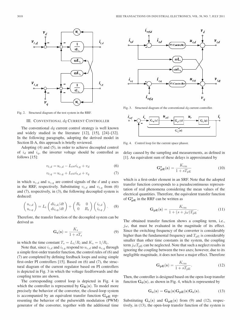
Based on (4) and (5), the structural diagram of the system in therotating frame is obtained, as shown in Fig. 2, which containsthe typical coupling terms.
Note that, in the conducted study of this paper, the dc-sidedynamics are neglected, and it is assumed that the dc linkvoltage is fixed at a desired level by an ideal voltage source.
3018 IEEE TRANSACTIONS ON INDUSTRIAL ELECTRONICS, VOL. 58, NO. 7, JULY 2011
Fig. 2. Structural diagram of the test system in the RRF.
III. CONVENTIONAL dq CURRENT CONTROLLER
The conventional dq current control strategy is well knownand widely studied in the literature [12], [15], [24]–[32].In the following paragraphs, adopting the derived model inSection II-A, this approach is briefly reviewed.
Adopting (4) and (5), in order to achieve decoupled controlof id and iq, the inverter voltage should be controlled asfollows [15]:
vt,d =uc,d − Ltωit,q + vd (6)
vt,q =uc,q + Ltωit,d + vq (7)
in which uc,d and uc,q are control signals of the d and q axesin the RRF, respectively. Substituting vt,d and vt,q from (6)and (7), respectively, in (3), the following decoupled system isdeduced:(
uc,d
uc,q
)= Lt
(dit,d/dtdit,q/dt
)+
(Rt 00 Rt
) (it,dit,q
). (8)
Therefore, the transfer function of the decoupled system can bederived as
Gs(s) =Ks
1 + sTs(9)
in which the time constant Ts = Lt/Rt and Ks = 1/Rt.Note that, since it,d and it,q respond to uc,d and uc,q through
a simple first-order transfer function, the control rules of (6) and(7) are completed by defining feedback loops and using simplefirst-order PI controllers [15]. Based on (6) and (7), the struc-tural diagram of the current regulator based on PI controllersis depicted in Fig. 3 in which the voltage feedforwards and thecoupling terms are shown.
The corresponding control loop is depicted in Fig. 4 inwhich the controller is represented by GR(s). To model moreprecisely the behavior of the converter, the closed-loop systemis accompanied by an equivalent transfer function GpE rep-resenting the behavior of the pulsewidth modulation (PWM)generator of the converter, together with the additional time
Fig. 3. Structural diagram of the conventional dq current controller.
Fig. 4. Control loop for the current space phasor.
delay caused by the sampling and measurements, as defined in[1]. An equivalent sum of these delays is approximated by
GspE(s) =
Kcm
1 + sTpE(10)
which is a first-order element in an SRF. Note that the adoptedtransfer function corresponds to a pseudocontinuous represen-tation of real phenomena considering the mean values of theelectrical quantities. Therefore, the equivalent transfer functionof Gs
pE in the RRF can be written as
GpE(s) =Kcm
1 + (s + jω)TpE. (11)
The obtained transfer function shows a coupling term, i.e.,jω, that must be evaluated in the magnitude of its effect.Since the switching frequency of the converter is considerablyhigher than the fundamental frequency and TpE is considerablysmaller than other time constants in the system, the couplingterm jωTpE can be neglected. Note that such a neglect results inignoring the coupling between the two axes; however, due to itsnegligible magnitude, it does not have a major effect. Therefore
GpE(s) =Kcm
1 + sTpE. (12)
Then, the controller is designed based on the open-loop transferfunction G0(s), as shown in Fig. 4, which is represented by
Go(s) = GR(s)GpE(s)Gs(s). (13)
Substituting Gs(s) and GpE(s) from (9) and (12), respec-tively, in (13), the open-loop transfer function of the system is
BAHRANI et al.: MULTIVARIABLE-PI-BASED dq CURRENT CONTROL OF VSCs 3019
derived as
Go(s) = GR(s)Kcm
1 + sTpE
Ks
1 + sTs. (14)
A conventional PI controller is then adopted as GR(s) in orderto achieve the prespecified dynamics. Therefore
GR(s) =1 + sTn
sTi. (15)
The controller time constant Tn is chosen to be equal to thedominant time constant Ts, which results in the simplificationof (14), i.e.,
Go(s) =K
sTi(1 + sTpE). (16)
Using the simplified transfer function in (16), the remainingparameter to design is the integration time constant Ti thatcan be determined by the usual criteria on the phase margin.Usually, Ti is chosen as Ti = 2KTpE. This value corresponds toa classical case where the zero-crossing pulsation of the open-loop transfer function ω0 is equal to 0.5(1/TpE) [1].
It should be noted that, according to (8), adopting the feedfor-ward signals theoretically results in a fully decoupled system.This perfect decoupling can be achieved only if the feedforwardsignals can precisely cancel the effect of the coupling terms,i.e., ωLtid and ωLtiq . However, in a real system, due tomeasurement errors, it is not practically possible to preciselydetermine the value of idq, Lt, and ω, and therefore, theideal coupling term cancellation is impossible. Moreover, thesystem delays caused by the sampling and/or the PWM blockalso eventuate imperfect cancellation. Therefore, in a practicalcase, adopting the conventional control strategy cannot fullydecouple the axes.
IV. MULTIVARIABLE-PI dq CURRENT CONTROLLER
In this section, based on the derived model in Section II-A,the multivariable-PI current controller is described, and itsstructural diagram is provided. Moreover, the applicability ofthe method to anisotropic three-phase systems is investigated,and it is shown that the method is capable of regulating cur-rents in anisotropic systems such as synchronous motors withdissimilar impedances in the d and q axes [1].
Contrary to the conventional approach, which relies onthe feedforward signals to eliminate the coupling, themultivariable-PI controller adopts plant inversion techniques todesign a decoupled control system. Adopting the diagram inFig. 2 or, equivalently, its dynamic representation in (3), thetransfer function of the system is derived. Applying a Laplacetransformation to (3), the following equation is derived:
Vt(s) = RtIt(s) + LtsIt(s) + jωLtIt(s) + V (s). (17)
Since the grid voltage is fixed and imposed by the utility grid,one can add it to the output of the controller as a feedforwardsignal to cancel its effect. Therefore, subtracting V (s) from
both sides of (17), the transfer function of the system fromVt − V to It is obtained as
Gs(s) =Ks
1 + (s + jω)Ts(18)
in which the time constant Ts is equal to Lt/Rt and Ks =1/Rt, where the coupling between the d and q axes is rep-resented by the term jωTs. Substituting Gs and GpE from(18) and (12), respectively, in (13), the open-loop transferfunction of the system utilizing the multivariable-PI controlleris deduced
Go(s) = GR(s)Kcm
1 + sTpE
Ks
1 + (s + jω)Ts. (19)
In order to achieve a normal polynomial without complexfactors, GR(s) is selected as a so-called multivariable-PI con-troller as follows:
GR(s) =1 + (s + jω)Tn
sTi. (20)
The controller time constant Tn is chosen to be equal to thedominant time constant of the system transfer function Ts
allowing the simplification of (19), leading to
Go(s) =K
sTi(1 + sTpE)(21)
in which K is KcmKs. The open-loop transfer function in (21)is now a normal polynomial form without complex factors,which means that the system is decoupled. The remainingparameter to design is the integration time constant Ti, whichcan be determined by a usual criterion on the phase margin asfollows:
Ti = 2KTpE. (22)
A. Structural Diagram of Multivariable-PI Controller
The multivariable-PI controller defined in (20) has a complextransfer function. Separating the real and imaginary parts, thecontroller can be written as
yR,d + jyR,q =(
1 + sTn
sTi+ j
ωTn
sTi
)(iε,d + jiε,q). (23)
Therefore
yR,d =1 + sTn
sTiiε,d − ωTn
sTiiε,q (24)
yR,q =1 + sTn
sTiiε,q +
ωTn
sTiiε,d. (25)
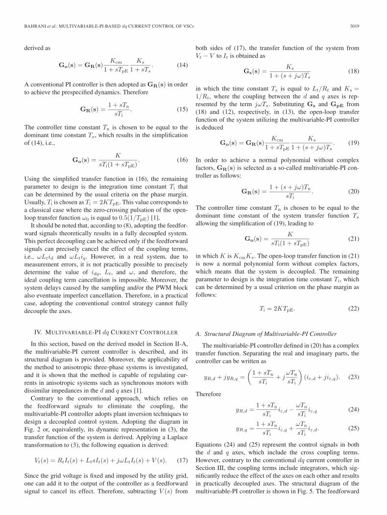
Equations (24) and (25) represent the control signals in boththe d and q axes, which include the cross coupling terms.However, contrary to the conventional dq current controller inSection III, the coupling terms include integrators, which sig-nificantly reduce the effect of the axes on each other and resultsin practically decoupled axes. The structural diagram of themultivariable-PI controller is shown in Fig. 5. The feedforward
3020 IEEE TRANSACTIONS ON INDUSTRIAL ELECTRONICS, VOL. 58, NO. 7, JULY 2011
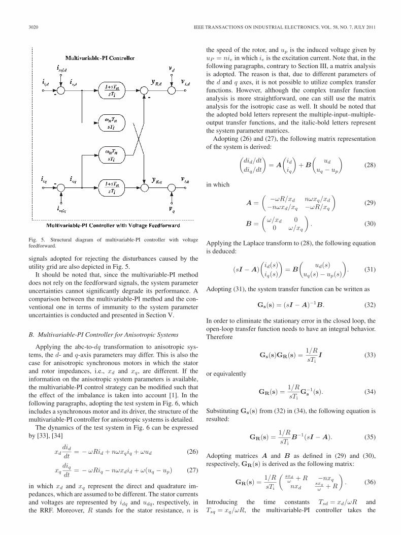
Fig. 5. Structural diagram of multivariable-PI controller with voltagefeedforward.
signals adopted for rejecting the disturbances caused by theutility grid are also depicted in Fig. 5.
It should be noted that, since the multivariable-PI methoddoes not rely on the feedforward signals, the system parameteruncertainties cannot significantly degrade its performance. Acomparison between the multivariable-PI method and the con-ventional one in terms of immunity to the system parameteruncertainties is conducted and presented in Section V.
B. Multivariable-PI Controller for Anisotropic Systems
Applying the abc-to-dq transformation to anisotropic sys-tems, the d- and q-axis parameters may differ. This is also thecase for anisotropic synchronous motors in which the statorand rotor impedances, i.e., xd and xq, are different. If theinformation on the anisotropic system parameters is available,the multivariable-PI control strategy can be modified such thatthe effect of the imbalance is taken into account [1]. In thefollowing paragraphs, adopting the test system in Fig. 6, whichincludes a synchronous motor and its driver, the structure of themultivariable-PI controller for anisotropic systems is detailed.
The dynamics of the test system in Fig. 6 can be expressedby [33], [34]
xddiddt
= − ωRid + nωxqiq + ωud (26)
xqdiqdt
= − ωRiq − nωxdid + ω(uq − up) (27)
in which xd and xq represent the direct and quadrature im-pedances, which are assumed to be different. The stator currentsand voltages are represented by idq and udq, respectively, inthe RRF. Moreover, R stands for the stator resistance, n is
the speed of the rotor, and up is the induced voltage given byuP = nie in which ie is the excitation current. Note that, in thefollowing paragraphs, contrary to Section III, a matrix analysisis adopted. The reason is that, due to different parameters ofthe d and q axes, it is not possible to utilize complex transferfunctions. However, although the complex transfer functionanalysis is more straightforward, one can still use the matrixanalysis for the isotropic case as well. It should be noted thatthe adopted bold letters represent the multiple-input–multiple-output transfer functions, and the italic-bold letters representthe system parameter matrices.
Adopting (26) and (27), the following matrix representationof the system is derived:(
did/dt
diq/dt
)= A
(idiq
)+ B
(ud
uq − up
)(28)
in which
A =(
−ωR/xd nωxq/xd
−nωxd/xq −ωR/xq
)(29)
B =(
ω/xd 00 ω/xq
). (30)
Applying the Laplace transform to (28), the following equationis deduced:
(sI − A)(
id(s)iq(s)
)= B
(ud(s)
uq(s) − up(s)
). (31)
Adopting (31), the system transfer function can be written as
Gs(s) = (sI − A)−1B. (32)
In order to eliminate the stationary error in the closed loop, theopen-loop transfer function needs to have an integral behavior.Therefore
Gs(s)GR(s) =1/R
sTiI (33)
or equivalently
GR(s) =1/R
sTiG−1
s (s). (34)
Substituting Gs(s) from (32) in (34), the following equation isresulted:
GR(s) =1/R
sTiB−1(sI − A). (35)
Adopting matrices A and B as defined in (29) and (30),respectively, GR(s) is derived as the following matrix:
GR(s) =1/R
sTi
(sxd
ω + R −nxq
nxdsxq
ω + R
). (36)
Introducing the time constants Tsd = xd/ωR andTsq = xq/ωR, the multivariable-PI controller takes the
BAHRANI et al.: MULTIVARIABLE-PI-BASED dq CURRENT CONTROL OF VSCs 3021
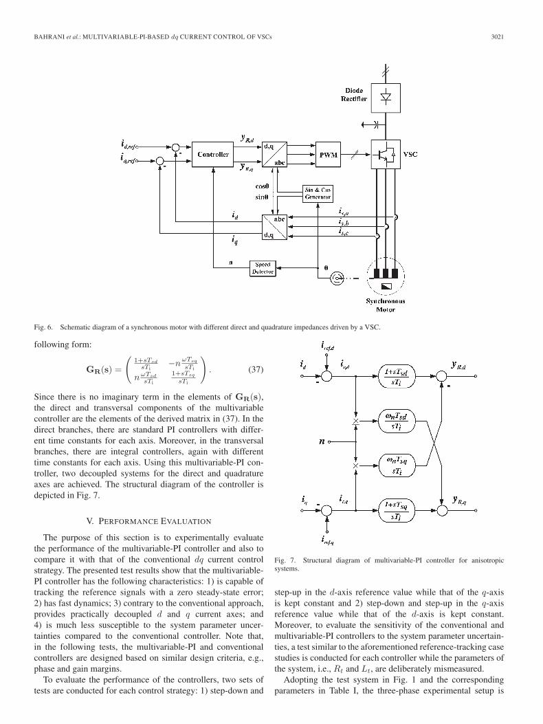
Fig. 6. Schematic diagram of a synchronous motor with different direct and quadrature impedances driven by a VSC.
following form:
GR(s) =
(1+sTsd
sTi−n
ωTsq
sTi
nωTsd
sTi
1+sTsq
sTi
). (37)
Since there is no imaginary term in the elements of GR(s),the direct and transversal components of the multivariablecontroller are the elements of the derived matrix in (37). In thedirect branches, there are standard PI controllers with differ-ent time constants for each axis. Moreover, in the transversalbranches, there are integral controllers, again with differenttime constants for each axis. Using this multivariable-PI con-troller, two decoupled systems for the direct and quadratureaxes are achieved. The structural diagram of the controller isdepicted in Fig. 7.
V. PERFORMANCE EVALUATION
The purpose of this section is to experimentally evaluatethe performance of the multivariable-PI controller and also tocompare it with that of the conventional dq current controlstrategy. The presented test results show that the multivariable-PI controller has the following characteristics: 1) is capable oftracking the reference signals with a zero steady-state error;2) has fast dynamics; 3) contrary to the conventional approach,provides practically decoupled d and q current axes; and4) is much less susceptible to the system parameter uncer-tainties compared to the conventional controller. Note that,in the following tests, the multivariable-PI and conventionalcontrollers are designed based on similar design criteria, e.g.,phase and gain margins.
To evaluate the performance of the controllers, two sets oftests are conducted for each control strategy: 1) step-down and
Fig. 7. Structural diagram of multivariable-PI controller for anisotropicsystems.
step-up in the d-axis reference value while that of the q-axisis kept constant and 2) step-down and step-up in the q-axisreference value while that of the d-axis is kept constant.Moreover, to evaluate the sensitivity of the conventional andmultivariable-PI controllers to the system parameter uncertain-ties, a test similar to the aforementioned reference-tracking casestudies is conducted for each controller while the parameters ofthe system, i.e., Rt and Lt, are deliberately mismeasured.
Adopting the test system in Fig. 1 and the correspondingparameters in Table I, the three-phase experimental setup is
3022 IEEE TRANSACTIONS ON INDUSTRIAL ELECTRONICS, VOL. 58, NO. 7, JULY 2011
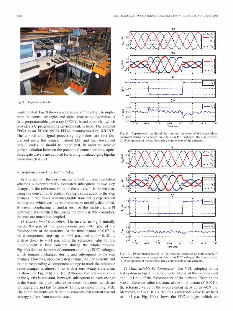
Fig. 8. Experimental setup.
implemented. Fig. 8 shows a photograph of the setup. To imple-ment the control strategies and signal processing algorithms, afield-programmable gate array (FPGA)-based controller, whichprovides a C programming environment, is used. The adoptedFPGA is an XC4010PC84 FPGA manufactured by XILINX.The control and signal processing algorithms are first dis-cretized using the bilinear method [35] and then developedinto C codes. It should be noted that, in order to achieveperfect isolation between the power and control circuits, optic-based gate drivers are adopted for driving insulated-gate bipolartransistors (IGBTs).
A. Reference-Tracking Test in d-Axis
In this section, the performance of both current regulationschemes is experimentally evaluated subsequent to two stepchanges in the reference value of the d-axis. It is shown that,using the conventional control strategy, subsequent to the stepchanges in the d-axis, a nonnegligible transient is experiencedin the q one, which verifies that the axes are not fully decoupled.However, conducting a similar test for the multivariable-PIcontroller, it is verified that, using the multivariable controller,the axes are much less coupled.
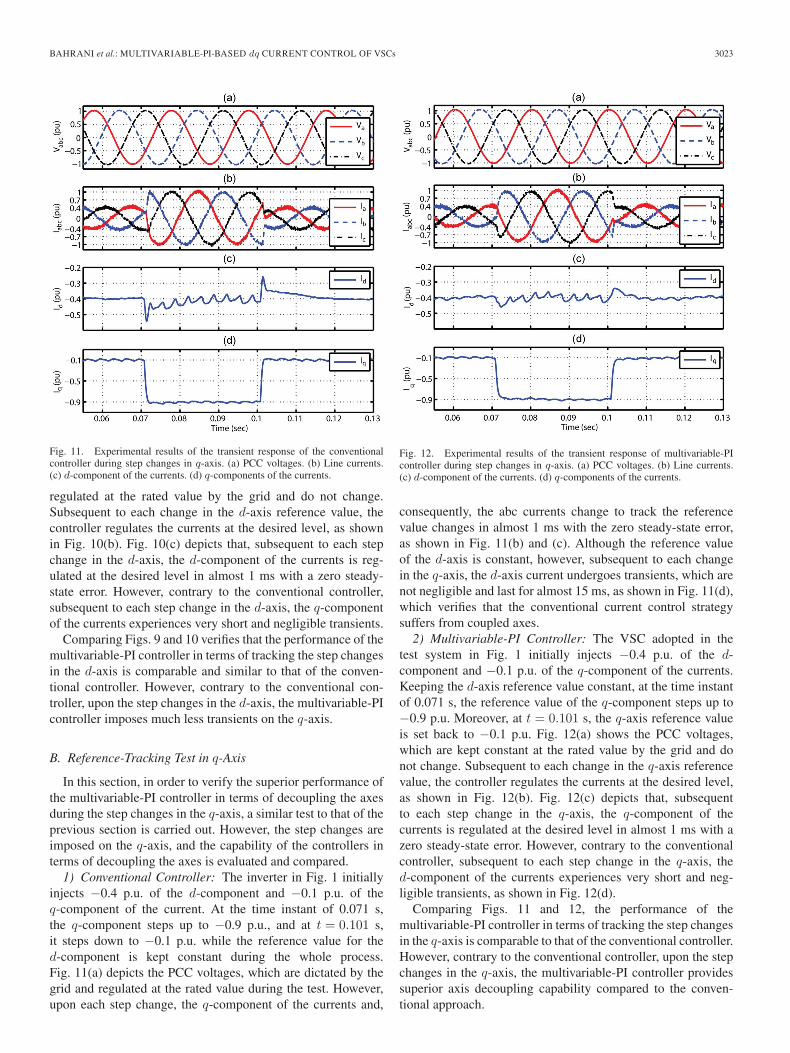
1) Conventional Controller: The inverter in Fig. 1 initiallyinjects 0.4 p.u. of the q-component and −0.1 p.u. of thed-component of the currents. At the time instant of 0.071 s,the d-component steps up to −0.9 p.u., and at t = 0.101 s,it steps down to −0.1 p.u. while the reference value for theq-component is kept constant during the whole process.Fig. 9(a) depicts the point of common coupling (PCC) voltages,which remain unchanged during and subsequent to the stepchanges. However, upon each step change, the line currents andtheir corresponding d-component change to track the referencevalue changes in almost 1 ms with a zero steady-state error,as shown in Fig. 9(b) and (c). Although the reference valueof the q-axis is constant, however, subsequent to each changein the d-axis, the q-axis also experiences transients, which arenot negligible and last for almost 15 ms, as shown in Fig. 9(d).The latter transients verify that the conventional current controlstrategy suffers from coupled axes.
Fig. 9. Experimental results of the transient response of the conventionalcontroller during step changes in d-axis. (a) PCC voltages. (b) Line currents.(c) d-component of the currents. (d) q-components of the currents.
Fig. 10. Experimental results of the transient response of multivariable-PIcontroller during step changes in d-axis. (a) PCC voltages. (b) Line currents.(c) d-component of the currents. (d) q-components of the currents.
2) Multivariable-PI Controller: The VSC adopted in thetest system in Fig. 1 initially injects 0.4 p.u. of the q-componentand −0.1 p.u. of the d-component of the currents. Keeping theq-axis reference value constant, at the time instant of 0.071 s,the reference value of the d-component steps up to −0.9 p.u.Moreover, at t = 0.101 s, the d-axis reference value is set backto −0.1 p.u. Fig. 10(a) shows the PCC voltages, which are
BAHRANI et al.: MULTIVARIABLE-PI-BASED dq CURRENT CONTROL OF VSCs 3023
Fig. 11. Experimental results of the transient response of the conventionalcontroller during step changes in q-axis. (a) PCC voltages. (b) Line currents.(c) d-component of the currents. (d) q-components of the currents.
regulated at the rated value by the grid and do not change.Subsequent to each change in the d-axis reference value, thecontroller regulates the currents at the desired level, as shownin Fig. 10(b). Fig. 10(c) depicts that, subsequent to each stepchange in the d-axis, the d-component of the currents is reg-ulated at the desired level in almost 1 ms with a zero steady-state error. However, contrary to the conventional controller,subsequent to each step change in the d-axis, the q-componentof the currents experiences very short and negligible transients.
Comparing Figs. 9 and 10 verifies that the performance of themultivariable-PI controller in terms of tracking the step changesin the d-axis is comparable and similar to that of the conven-tional controller. However, contrary to the conventional con-troller, upon the step changes in the d-axis, the multivariable-PIcontroller imposes much less transients on the q-axis.
B. Reference-Tracking Test in q-Axis
In this section, in order to verify the superior performance ofthe multivariable-PI controller in terms of decoupling the axesduring the step changes in the q-axis, a similar test to that of theprevious section is carried out. However, the step changes areimposed on the q-axis, and the capability of the controllers interms of decoupling the axes is evaluated and compared.
1) Conventional Controller: The inverter in Fig. 1 initiallyinjects −0.4 p.u. of the d-component and −0.1 p.u. of theq-component of the current. At the time instant of 0.071 s,the q-component steps up to −0.9 p.u., and at t = 0.101 s,it steps down to −0.1 p.u. while the reference value for thed-component is kept constant during the whole process.Fig. 11(a) depicts the PCC voltages, which are dictated by thegrid and regulated at the rated value during the test. However,upon each step change, the q-component of the currents and,
Fig. 12. Experimental results of the transient response of multivariable-PIcontroller during step changes in q-axis. (a) PCC voltages. (b) Line currents.(c) d-component of the currents. (d) q-components of the currents.
consequently, the abc currents change to track the referencevalue changes in almost 1 ms with the zero steady-state error,as shown in Fig. 11(b) and (c). Although the reference valueof the d-axis is constant, however, subsequent to each changein the q-axis, the d-axis current undergoes transients, which arenot negligible and last for almost 15 ms, as shown in Fig. 11(d),which verifies that the conventional current control strategysuffers from coupled axes.
2) Multivariable-PI Controller: The VSC adopted in thetest system in Fig. 1 initially injects −0.4 p.u. of the d-component and −0.1 p.u. of the q-component of the currents.Keeping the d-axis reference value constant, at the time instantof 0.071 s, the reference value of the q-component steps up to−0.9 p.u. Moreover, at t = 0.101 s, the q-axis reference valueis set back to −0.1 p.u. Fig. 12(a) shows the PCC voltages,which are kept constant at the rated value by the grid and donot change. Subsequent to each change in the q-axis referencevalue, the controller regulates the currents at the desired level,as shown in Fig. 12(b). Fig. 12(c) depicts that, subsequentto each step change in the q-axis, the q-component of thecurrents is regulated at the desired level in almost 1 ms with azero steady-state error. However, contrary to the conventionalcontroller, subsequent to each step change in the q-axis, thed-component of the currents experiences very short and neg-ligible transients, as shown in Fig. 12(d).
Comparing Figs. 11 and 12, the performance of themultivariable-PI controller in terms of tracking the step changesin the q-axis is comparable to that of the conventional controller.However, contrary to the conventional controller, upon the stepchanges in the q-axis, the multivariable-PI controller providessuperior axis decoupling capability compared to the conven-tional approach.
3024 IEEE TRANSACTIONS ON INDUSTRIAL ELECTRONICS, VOL. 58, NO. 7, JULY 2011
Fig. 13. Experimental results of the transient response of the conventionalcontroller during step changes in d-axis while the parameters are mismea-sured. (a) PCC voltages. (b) Line currents. (c) d-component of the currents.(d) q-components of the currents.
C. Sensitivity to System Parameter Uncertainties
In this section, the sensitivities of the conventional andmultivariable-PI controllers to the system parameters, i.e., Rt
and Lt, are evaluated. For each controller, a test similar to whatis conducted in Section V-A is carried out. According to Table I,the real values of Rt and Lt are 0.15 Ω and 5 mH, respectively.However, to design the controllers, it is assumed that, due tomeasurement errors, the estimated values of Rt and Lt are0.3 Ω and 2.5 mH, respectively.
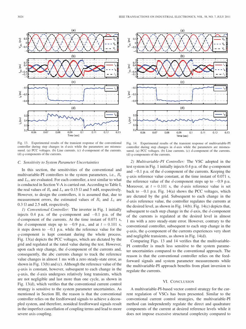
1) Conventional Controller: The inverter in Fig. 1 initiallyinjects 0.4 p.u. of the q-component and −0.1 p.u. of thed-component of the currents. At the time instant of 0.071 s,the d-component steps up to −0.9 p.u., and at t = 0.101 s,it steps down to −0.1 p.u. while the reference value for theq-component is kept constant during the whole process.Fig. 13(a) depicts the PCC voltages, which are dictated by thegrid and regulated at the rated value during the test. However,upon each step change, the d-component of the currents and,consequently, the abc currents change to track the referencevalue changes in almost 1 ms with a zero steady-state error, asshown in Fig. 13(b) and (c). Although the reference value of theq-axis is constant, however, subsequent to each change in theq-axis, the d-axis undergoes relatively long transients, whichare not negligible and last more than one cycle, as shown inFig. 13(d), which verifies that the conventional current controlstrategy is sensitive to the system parameter uncertainties. Asmentioned in Section III, the reason is that the conventionalcontroller relies on the feedforward signals to achieve a decou-pled system, and therefore, nonideal feedforward signals resultin the imperfect cancellation of coupling terms and lead to moresevere axis coupling.
Fig. 14. Experimental results of the transient response of multivariable-PIcontroller during step changes in d-axis while the parameters are mismea-sured. (a) PCC voltages. (b) Line currents. (c) d-component of the currents.(d) q-components of the currents.
2) Multivariable-PI Controller: The VSC adopted in thetest system in Fig. 1 initially injects 0.4 p.u. of the q-componentand −0.1 p.u. of the d-component of the currents. Keeping theq-axis reference value constant, at the time instant of 0.071 s,the reference value of the d-component steps up to −0.9 p.u.Moreover, at t = 0.101 s, the d-axis reference value is setback to −0.1 p.u. Fig. 14(a) shows the PCC voltages, whichare dictated by the grid. Subsequent to each change in thed-axis reference value, the controller regulates the currents atthe desired level, as shown in Fig. 14(b). Fig. 14(c) depicts that,subsequent to each step change in the d-axis, the d-componentof the currents is regulated at the desired level in almost1 ms with a zero steady-state error. However, contrary to theconventional controller, subsequent to each step change in theq-axis, the q-component of the currents experiences very shortand negligible transients, as shown in Fig. 14(d).
Comparing Figs. 13 and 14 verifies that the multivariable-PI controller is much less sensitive to the system parame-ter uncertainties compared to the conventional approach. Thereason is that the conventional controller relies on the feed-forward signals and system parameter measurements whilethe multivariable-PI approach benefits from plant inversion toregulate the currents.
VI. CONCLUSION
A multivariable-PI-based vector control strategy for the cur-rent regulation of VSCs has been presented. Similar to theconventional current control strategies, the multivariable-PImethod can independently regulate the direct and quadraturecomponents of the current at desired reference levels while itdoes not impose excessive structural complexity compared to
BAHRANI et al.: MULTIVARIABLE-PI-BASED dq CURRENT CONTROL OF VSCs 3025
the conventional approaches and can be easily implemented indigital environments. The performance of the multivariable-PImethod is experimentally evaluated and it is shown that themethod has the following characteristics:
1) can track the d and q current reference signals with zerosteady-state errors;
2) is as fast as the conventional approach;3) has superior axis decoupling capability compared to the
conventional approach;4) is much less sensitive to the system parameter uncertain-
ties compared to the conventional approach.
Moreover, it has been shown that, contrary to the con-ventional approach, which is only tailored for balanced sys-tems, the multivariable-PI controller can be manipulated to beadopted in anisotropic systems, e.g., in anisotropic synchronousmotors driven by VSCs.
ACKNOWLEDGMENT
The authors would like to thank Prof. H. Bühler, the formerhead of the Industrial Electronics Laboratory, Ecole Polytech-nique Fédérale de Lausanne, for his valuable contribution to thispaper as the main idea of the conducted studies was initiated byhim. The authors would also like to dedicate this paper to him.
REFERENCES
[1] H. Bühler, Réglage des Systèmes d’Électronique de Puissance, vol. 1, 2and 3, Théorie. Lausanne, Switzerland: PPUR, Presses Polytechniqueset Universitaires Romandes, 1997.
[2] S. B. Kjaer, J. K. Pedersen, and F. Blaabjerg, “A review of single-phasegrid-connected inverters for photovoltaic modules,” IEEE Trans. Ind.Appl., vol. 41, no. 5, pp. 1292–1306, Sep./Oct. 2005.
[3] E. Villanueva, P. Correa, J. Rodríguez, and M. Pacas, “Control of a single-phase cascaded H-bridge multilevel inverter for grid-connected photo-voltaic systems,” IEEE Trans. Ind. Electron., vol. 56, no. 11, pp. 4399–4406, Nov. 2009.
[4] B. C. Rabelo, W. Hofmann, J. Lucas da Silva, R. Gaiba de Oliveira,and S. R. Silva, “Reactive power control design in doubly fed inductiongenerators for wind turbines,” IEEE Trans. Ind. Electron., vol. 56, no. 10,pp. 4154–4162, Oct. 2009.
[5] M. Saeedifard, R. Iravani, and J. Pou, “A space vector modulation strategyfor a back-to-back five-level HVDC converter system,” IEEE Trans. Ind.Electron., vol. 56, no. 2, pp. 452–466, Feb. 2009.
[6] H. Akagi, “Active harmonic filters,” Proc. IEEE, vol. 93, no. 12, pp. 2128–2141, Dec. 2005.
[7] V. F. Corasaniti, M. B. Barbieri, P. L. Arnera, and M. I. Valla, “Hy-brid active filter for reactive and harmonics compensation in a distribu-tion network,” IEEE Trans. Ind. Electron., vol. 56, no. 3, pp. 670–677,Mar. 2009.
[8] J. Miret, M. Castilla, J. Matas, J. M. Guerrero, and J. C. Vasquez, “Selec-tive harmonic-compensation control for single-phase active power filterwith high harmonic rejection,” IEEE Trans. Ind. Electron., vol. 56, no. 8,pp. 3117–3127, Aug. 2009.
[9] P. G. Barbosa, L. G. B. Rolim, and E. H. Watanabe, “Control strategy forgrid-connected dc ac with load power factor correction converters,” Proc.Inst. Elect. Eng.—Gener., Transm. Distrib., vol. 145, no. 5, pp. 487–491,Sep. 1998.
[10] L. Hassaine, E. Olias, J. Quintero, and M. Haddadi, “Digital power factorcontrol and reactive power regulation for grid-connected photovoltaicinverter,” Renew. Energy, vol. 34, no. 1, pp. 315–321, Jan. 2009.
[11] F. Blaabjerg, R. Teodorescu, M. Liserre, and A. V. Timbus, “Overviewof control and grid synchronization for distributed power generationsystems,” IEEE Trans. Ind. Electron., vol. 53, no. 5, pp. 1398–1409,Oct. 2006.
[12] M. P. Kazmierkowski and L. Malesani, “Current control techniques forthree-phase voltage-source PWM converters: A survey,” IEEE Trans. Ind.Electron., vol. 45, no. 5, pp. 691–703, Oct. 1998.
[13] E. Song, A. F. Lynch, and V. Dinavahi, “Experimental validation of non-linear control for a voltage source converter,” IEEE Trans. Control Syst.Technol., vol. 17, no. 5, pp. 1135–1144, Sep. 2009.
[14] A. Gensior, H. Sira-Ramírez, J. Rudolph, and H. Güldner, “On somenonlinear current controllers for three-phase boost rectifiers,” IEEE Trans.Ind. Electron., vol. 56, no. 2, pp. 360–370, Feb. 2009.
[15] C. Schauder and H. Mehta, “Vector analysis and control of advanced staticVAR compensators,” Proc. Inst. Elect. Eng.—C, vol. 140, no. 4, pp. 299–306, Jul. 1993.
[16] D. N. Zmood and D. G. Holmes, “Stationary frame current regulation ofPWM inverters with zero steady-state error,” IEEE Trans. Power Elec-tron., vol. 18, no. 3, pp. 814–822, May 2003.
[17] R. Teodorescu, F. Blaabjerg, M. Liserre, and P. C. Loh, “Proportional-resonant controllers and filters for grid-connected voltage-source convert-ers,” Proc. Inst. Elect. Eng.—Electr. Power Appl., vol. 153, no. 5, pp. 750–762, Sep. 2006.
[18] G. Shen, X. Zhu, J. Zhang, and D. Xu, “A new feedback methodfor PR current control of LCL-filter based grid-connected inverter,”IEEE Trans. Ind. Electron., vol. 57, no. 6, pp. 2033–2041, Jun. 2010.10.1109/TIE.2010.2040552.
[19] H. Abu-Rub, J. Guzinski, Z. Krzeminski, and H. A. Toliyat, “Predictivecurrent control of voltage-source inverters,” IEEE Trans. Ind. Electron.,vol. 51, no. 3, pp. 585–593, Jun. 2004.
[20] P. Zanchetta, D. B. Gerry, V. G. Monopoli, J. C. Clare, and P. W. Wheeler,“Predictive current control for multilevel active rectifiers with reducedswitching frequency,” IEEE Trans. Ind. Electron., vol. 55, no. 1, pp. 163–172, Jan. 2008.
[21] J. C. Moreno, J. M. Espí Huerta, R. G. Gil, and S. A. González, “A robustpredictive current control for three-phase grid-connected inverters,” IEEETrans. Ind. Electron., vol. 56, no. 6, pp. 1993–2004, Jun. 2009.
[22] Y. A. I. Mohamed and E. F. El-Saadany, “An improved deadbeat currentcontrol scheme with a novel adaptive self-tuning load model for a three-phase PWM voltage-source inverter,” IEEE Trans. Ind. Electron., vol. 54,no. 2, pp. 747–759, Apr. 2007.
[23] O. Kukrer, H. Komurcugil, and A. Doganalp, “A three-level hystere-sis function approach to the sliding-mode control of single-phase UPSinverters,” IEEE Trans. Ind. Electron., vol. 56, no. 9, pp. 3477–3486,Sep. 2009.
[24] M. Liserre, R. Teodorescu, and F. Blaabjerg, “Multiple harmonics controlfor three-phase grid converter systems with the use of PI-RES currentcontroller in a rotating frame,” IEEE Trans. Power Electron., vol. 21,no. 3, pp. 836–841, May 2006.
[25] A. Yazdani and R. Iravani, “A unified dynamic model and control forthe voltage-sourced converter under unbalanced grid conditions,” IEEETrans. Power Del., vol. 21, no. 3, pp. 1620–1629, Jul. 2006.
[26] H. Song and K. Nam, “Dual current control scheme for PWM converterunder unbalanced input voltage conditions,” IEEE Trans. Ind. Electron.,vol. 46, no. 5, pp. 953–959, Oct. 1999.
[27] S. Zhang, K.-J. Tseng, D. M. Vilathgamuwa, T. D. Nguyen, andX.-Y. Wang, “Design of a robust grid interface system for PMSG-basedwind turbine generators,” IEEE Trans. Ind. Electron., vol. 58, no. 1,pp. 316–328, Jan. 2011.
[28] E. Twining and D. G. Holmes, “Grid current regulation of a three-phasevoltage source inverter with an LCL input filter,” IEEE Trans. PowerElectron., vol. 18, no. 3, pp. 888–895, May 2003.
[29] B. Saritha and P. A. Jankiraman, “Observer based current control ofsingle-phase inverter in DQ rotating frame,” in Proc. Int. Conf. PowerElectron., Drives, Energy Syst., Dec. 2006, pp. 1–5.
[30] A. Rufer, B. Bahrani, S. Kenzelmann, and L. Lopes, “Vector control ofsingle-phase voltage source converters based on fictive axis emulation,”in Proc. 1st IEEE ECCE, Sep. 2009, pp. 2689–2695.
[31] H. Komurcugil, “Steady-state analysis and passivity-based control ofsingle-phase PWM current-source inverters,” IEEE Trans. Ind. Electron.,vol. 57, no. 3, pp. 1026–1030, Mar. 2010.
[32] M. Castilla, J. Miret, J. Matas, L. García de Vicuña, and J. M. Guerrero,“Control design guidelines for single-phase grid-connected photovoltaicinverters with damped resonant harmonic compensators,” IEEE Trans.Ind. Electron., vol. 56, no. 11, pp. 4492–4501, Nov. 2009.
[33] G. Foo and M. F. Rahman, “Sensorless direct torque and flux-controlledIPM synchronous motor drive at very low speed without signal in-jection,” IEEE Trans. Ind. Electron., vol. 57, no. 1, pp. 395–403,Jan. 2010.
[34] M. Nemec, K. Drobnic, D. Nedeljkovic, and V. Ambrožic, “Direct currentcontrol of a synchronous machine in field coordinates,” IEEE Trans. Ind.Electron., vol. 56, no. 10, pp. 4052–4061, Oct. 2009.
[35] A. V. Oppenheim and R. W. Schafer, Discrete-Time Signal Processing.Englewood Cliffs, NJ: Prentice-Hall, 1999.

3026 IEEE TRANSACTIONS ON INDUSTRIAL ELECTRONICS, VOL. 58, NO. 7, JULY 2011
Behrooz Bahrani (S’07) received the B.Sc. de-gree in electrical engineering from the Sharif Uni-versity of Technology, Tehran, Iran, in 2006, andthe M.Sc. degree in electrical engineering from theUniversity of Toronto, Toronto, ON, Canada, in2008. He is currently working toward the Ph.D.degree at Ecole Polytechnique Fédérale de Lausanne,Lausanne, Switzerland.
From May to November 2008, he was a ResearchIntern with the ABB Corporate Research, Dättwil-Baden, Switzerland. His research interests include
power electronics and its applications in power and traction systems.
Stephan Kenzelmann (S’09) was born in Zeneggen,Switzerland, in 1982. He received the M.Sc.degree in electrical engineering from the EcolePolytechnique Fédérale de Lausanne, Lausanne,Switzerland, in 2007, where he is currently workingtoward the Ph.D. degree in the Industrial ElectronicsLaboratory.
His research interests include single-phase controlmethods, multilevel converter control, and researchand development of new power electronic systemsfor dc power transmission.
Alfred Rufer (M’95–SM’01–F’06) received theM.S. degree from the Ecole Polytechnique Fédéralede Lausanne (EPFL), Lausanne, Switzerland,in 1976.
In 1978, he was with ABB, Turgi, Switzerland,where he was involved in the fields of power elec-tronics and control, such as high-power variablefrequency converters for drives, and where he wasa Group Leader involved with power electronic de-velopment in 1985. In 1993, he was an AssistantProfessor with the EPFL, where, since 1996, he has
been a Full Professor and the Head of the Industrial Electronics Laboratory(LEI). The LEI is active in power electronics used in energy conversion andenergy storage and in the modeling and simulation of systems, includingcontrol strategies and control circuits. He has authored or coauthored manypublications on power electronics and applications, such as for multilevelconverters or for different energy-storage systems. He is the holder of severalpatents.