Embed Size (px)
Citation preview
MultiSync LT100Ultra-Portable ProjectorUser’s Manual
English

E – 2
WARNINGTO PREVENT FIRE OR SHOCK, DO NOT EXPOSETHIS UNIT TO RAIN OR MOISTURE. DO NOTUSE THIS UNIT’S GROUNDED PLUG WITH ANEXTENSION CORD OR IN AN OUTLET UNLESSALL THREE PRONGS CAN BE FULLY INSERTED.DO NOT OPEN THE CABINET. THERE AREHIGH-VOLTAGE COMPONENTS INSIDE. ALLSERVICING MUST BE DONE BY QUALIFIEDNEC SERVICE PERSONNEL.
PrecautionsPlease read this manual carefully before using yourNEC MultiSync LT100 Projector and keep the manualhandy for future reference.
Your serial number is located beneath the main powerswitch on the back of your MultiSync LT100. Record ithere:
3. GSGV Acoustic Noise Information Ordinance:The sound pressure level is less than 70 dB (A) accordingto ISO 3744 or ISO 7779.
IMPORTANT INFORMATION
CAUTION
LASER RADIATION-DO NOT STARE INTO BEAM
WAVE LENGTH: 670 nmMAX. OUTPUT: 1 mWCLASS II LASER PRODUCT
CAUTIONTO PREVENT SHOCK, DO NOT OPENTHE CABINET. NO USER-SERVICEABLEPARTS INSIDE. REFER SERVICING TOQUALIFIED NEC SERVICE PERSONNEL.
This symbol warns the user thatuninsulated voltage within the unit maybe sufficient to cause electrical shock.Therefore, it is dangerous to make anykind of contact with any part inside ofthe unit.
This symbol alerts the user that impor-tant information concerning the opera-tion and maintenance of this unit hasbeen provided. The information shouldbe read carefully to avoid problems.
E – 3
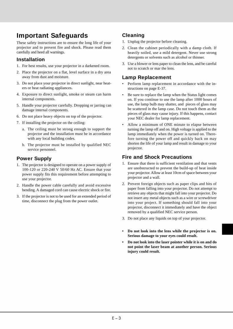
Cleaning1. Unplug the projector before cleaning.
2. Clean the cabinet periodically with a damp cloth. Ifheavily soiled, use a mild detergent. Never use strongdetergents or solvents such as alcohol or thinner.
3. Use a blower or lens paper to clean the lens, and be carefulnot to scratch or mar the lens.
Lamp Replacement• Perform lamp replacement in accordance with the in-
structions on page E-37.
• Be sure to replace the lamp when the Status light comeson. If you continue to use the lamp after 1000 hours ofuse, the lamp bulb may shatter, and pieces of glass maybe scattered in the lamp case. Do not touch them as thepieces of glass may cause injury. If this happens, contactyour NEC dealer for lamp replacement.
• Allow a minimum of ONE minute to elapse betweenturning the lamp off and on. High voltage is applied to thelamp immediately when the power is turned on. There-fore turning the power off and quickly back on mayshorten the life of your lamp and result in damage to yourprojector.
Fire and Shock Precautions1. Ensure that there is sufficient ventilation and that vents
are unobstructed to prevent the build-up of heat insideyour projector. Allow at least 10cm of space between yourprojector and a wall.
2. Prevent foreign objects such as paper clips and bits ofpaper from falling into your projector. Do not attempt toretrieve any objects that might fall into your projector. Donot insert any metal objects such as a wire or screwdriverinto your project. If something should fall into yourprojector, disconnect it immediately and have the objectremoved by a qualified NEC service person.
3. Do not place any liquids on top of your projector.
• Do not look into the lens while the projector is on.Serious damage to your eyes could result.
• Do not look into the laser pointer while it is on and donot point the laser beam at another person. Seriousinjury could result.
Important SafeguardsThese safety instructions are to ensure the long life of yourprojector and to prevent fire and shock. Please read themcarefully and heed all warnings.
Installation1. For best results, use your projector in a darkened room.
2. Place the projector on a flat, level surface in a dry areaaway from dust and moisture.
3. Do not place your projector in direct sunlight, near heat-ers or heat radiating appliances.
4. Exposure to direct sunlight, smoke or steam can harminternal components.
5. Handle your projector carefully. Dropping or jarring candamage internal components.
6. Do not place heavy objects on top of the projector.
7. If installing the projector on the ceiling:
a. The ceiling must be strong enough to support theprojector and the installation must be in accordancewith any local building codes.
b. The projector must be installed by qualified NECservice personnel.
Power Supply1. The projector is designed to operate on a power supply of
100-120 or 220-240 V 50/60 Hz AC. Ensure that yourpower supply fits this requirement before attempting touse your projector.
2. Handle the power cable carefully and avoid excessivebending. A damaged cord can cause electric shock or fire.
3. If the projector is not to be used for an extended period oftime, disconnect the plug from the power outlet.
E – 4
1. IntroductionIntroduction To The MultiSync LT100 Projector................................ E-5How Do You Get Started?.................................................................. E-6What’s In The Box? ........................................................................... E-6Getting To Know Your MultiSync LT100 Projector............................ E-7
Front Features.............................................................................. E-7Rear Features............................................................................... E-7Top Features ................................................................................ E-8Terminal Panel Features............................................................... E-9Remote Control Features............................................................E-11
2. InstallationSetting Up Your MultiSync LT100 Projector....................................E-13
Selecting A Location..................................................................E-13Projection Distance....................................................................E-14Using A Tabletop Or Cart...........................................................E-16Transporting and storing theprojector....................................................................................E-17Ceiling Installation.....................................................................E-18
Wiring Diagram...............................................................................E-19Connecting Your PC Or Macintosh Computer..................................E-20Connecting Your DVD Player..........................................................E-23Connecting Your Document Camera................................................E-23Connecting Your VCR Or Laser Disc Player....................................E-23Connecting An External Monitor.....................................................E-23Connecting Your Remote Mouse Receiver.......................................E-24
3. OperationGeneral Controls..............................................................................E-26Using The Menus............................................................................E-27Menu Descriptions & Functions......................................................E-28Source Menu (Source Icons)............................................................E-28Image Adjust Menu(Sound And Picture Control Icons)...................E-29Power Menu(Projector Control Icons).............................................E-31Settings Menu(Maintenance Icons)..................................................E-32Using the Viewer Function...............................................................E-33
4. MaintenanceReplacing The Lamp.......................................................................E-37Remote Control Battery Installation.................................................E-38Operating Range..............................................................................E-38
5. TroubleshootingStatus Light Messages.....................................................................E-39Common Problems & Solutions......................................................E-40
6. SpecificationsOptical.............................................................................................E-41Electrical.........................................................................................E-41Mechanical......................................................................................E-41D-Sub Pin Assignments...................................................................E-43Timing Chart...................................................................................E-44PC Control Command Reference.....................................................E-45Cable Connection............................................................................E-47
TABLE OF CONTENTS
E – 5
This section introduces you to your new MultiSync LT100(XGA) Projector, provides a list of materials that comes withyour projector and describes the features and controls.
Congratulations On Your PurchaseOf The MultiSync LT100 ProjectorThe MultiSync LT100 is one of the very best projectorsavailable today. The MultiSync LT100 enables you to projectprecise images up to 300 inches across (measured diago-nally) from your PC or Macintosh computer (desktop ornotebook), VCR, DVD player, document camera, or even alaser disc player.You can use the projector on a tabletop or cart, you canpermanentlymount it on a ceiling*1, or you can use MultiSync LT100Projector toproject images from behind the screen. The remote controlcan be usedwirelessly or with a cable, and you can even use the remotecontrol with the built-in remote mouse receiver to operate themouse on your PC or Mac.
Features you'll enjoy:• Simple set up and operation.
• A high-performance 280 watt metal halide lamp thatdelivers a high bright image, allowing you to make pre-sentations with the lights on.
• A wireless remote control that operates the projectorfrom any angle.
• A laser pointer that' s built into the remote control.
• The manual zoom control enables you to adjust the imageto be between 24 and 300 inches (measured diagonally).
• White balance control allows you to adjust the brightnessand contrast for each RGB color.
• You can choose between video modes depending on yoursource:
"normal" for a typical picture, "natural" for true colorreproduction, and "camera" for use with a documentcamera or low APL picture.
• The optional LT Viewer kit allows you to start yourpresentation even when a PC is not available at the site.
• The "image capture" enables you to use the entire pictureas a background image or to create slides (optional LTViewer required).
• An image can be projected from in front or behind ascreen, and the projector can even be installed on theceiling.
• NEC Technologies' exclusive AccuBlend™ intelligentpixel blending technology - an extremely accurate imagecompression technology - offers a crisp image withSXGA (128021024) resolution*2 .
INTRODUCTION1
• Supports most IBM VGA, SVGA, XGA, SXGA(withAccuBlend™)*2 , Macintosh, or any other RGB signalswithin a horizontal frequency range of 15.625 to 85 kHzand a vertical frequency range of 50 to 85 Hz. Thisincludes NTSC, PAL, SECAM and NTSC4.43 standardvideo signals.
Note: Composite video standards are as follows:NTSC: U.S. TV standard for video in U.S. and Canada.PAL: TV standard used in western Europe.SECAM: TV standard used in France and Eastern Europe.NTSC4.43: TV standard used in Middle East countries.
• Accepts component video source such as DVD playerwith the Y/Cb/Cr output.
• The remote control can be used with or without a cable,and you can even use the remote to operate your PC orMacintosh mouse wirelessly from across the room withthe built-in remote mouse receiver.
• You can control your MultiSync LT100 Projector with aPC.
• The contemporary cabinet design is compact, easy tocarry, and complements any office, board room or audito-rium.
* 1 Installing the MultiSync LT100 LCD Projector on theceiling must be done by authorized NEC technicians.Consult your NEC dealer for more information.
* 2 An SXGA image (128021024) is converted into a10242768 crisp image with NEC technology'sAccuBlend.

E – 6
How Do You Get Started?The fastest way to get started is to take your time and doeverything right the first time. Take a few minutes now toclick through the training CD-ROM and review the user’smanual. This may save you hours later on. At the beginning ofeach section of the manual you'll find an overview. If thesection doesn't apply, you can skip it.
What’s In The Box?Make sure your box contains everything listed. If any piecesare missing, contact your dealer. Please save the original boxand packing materials if you ever need to ship yourMultiSync LT100 Projector.
Batteries (AA22)Remote mouse receiverPin adapter forMacintosh
Remote control
Mouse adapter (For Macintosh)
User’s manual
Signal cable(15-Pin Mini D-Sub To 15-Pin MiniD-Sub connector)
Power cable
Mouse adapter (For IBM PS/2)
Serial cable Carrying case
Remote control case
• NEC MultiSync LT100 Projector
• Carrying Case
• Remote Control With Built-In Laser Pointer
• Remote Control Case
• Remote Mouse Receiver
• Signal Cable
(15-Pin Mini D-Sub To 15-Pin Mini D-Sub Connec-tor)
• Mouse Adapters for IBM PS/2 and Mac
• Serial Cable
• Pin Adapter for Macintosh
• Power Cable
• Two AA Batteries
• User's Manual
User’smanual

E – 7
Getting To Know Your MultiSync LT100 Projector
Front Features Top features
MEMU
SELECT
ENTER
STATUS
POWER
ON / OFF
Monaural Speaker (1W)
Remote Sensor
Ventilation
Lens and lens Cap
Focus Ring
One-Touch Tilt Button
Adjustable Foot
Cooling Fan
Rear Features
MEMU
SELECT
ENTER
STATUS
POWER
ON / OFF
AC IN
Remote Sensor
Power Switch
AC InputConnect the supplied powercable’s three-pin plug here.
Slot for Kensington MicroSaver SecuritySystem
Rear Foot
Terminal Panel
Carrying handle
Zoom Ring Lever
One-Touch Tilt Button
Adjustable Foot
Remote Sensor
Remote Sensor

E – 8
Top Features1 Power Button
Use this button to turn the power on and off when MainPower Switch is on and the projector is on standby.
2 Enter ButtonExecutes your menu selection.
3 Select ( ▲▼§ ©) / (+)(–) ButtonsSelect: After you press the “Menu” button, use the ▲ or
▼ button to select the menu icon of the item youwish to adjust.
(+)(–): Use these buttons while you' re in the Image Ad-just mode to change the level of a selected menuitem. These buttons are also used to set an item inthe Power or Settings menus.
4 Menu ButtonDisplays the on- screen menu.
5 Power IndicatorWhen the projector is switched On, the green LED blinksfor about one minute, then lights up.
If the main power is on and you switch it off by pressingPOWER OFF on the remote control or press and hold downthe POWER button on the cabinet for one second, the greenLED blinks for one minute, then lights up and the projec-tor goes on standby.
* The projector will not accept operation instructions forthe one minute during which the LED is blinking duringswitching on or off as described above.
6 Status IndicatorWhen this is lit red continually, it's warning you that theprojection lamp has exceed 1000 hours of service. Afterthis light appears, it is advisable to replace the projectionlamp as soon as possible.(See page E-37.)When the operating time of the lamp exceeds 1000 hours,the STATUS indicator is lit red continually. In addition themessage "LAMP USAGE XX HOURS" appears continu-ally when the on-screen menu is not displayed.If this light blinks red rapidly, it indicates that the lamphouse is not attached properly; if the light blinks slowly itmeans the projector's internal temperature is too hot tooperate safely. See the Status Light Messages on page E-39 for more details.
(▲▼§ ©)
MEMU
SELECT
- +
ENTER
STATUS
POWERON / OFF
4
3
2
6
51
AC IN
MEMU
SELECT
ENTER
STATUS
POWER
ON / OFF
○ ○ ○ ○ ○○
○
○
○
○
○
○
○
○
○
○
○
○
○
○
○
○
○
○
○

E – 9
Terminal Panel FeaturesThis panel is located in the side and is where you connectyour cables.
1 Remote Control Jacksa. Remote Control Input JackConnect your remote control cable here for wired opera-tion.
b. Remote Control Output JackThis terminal enables you to operate up to five projectorswith the same remote control. When your remote mousereceiver is connected here, the remote sensors on the pro-jector cabinet will receive your mouse commands.
2 Video InputConnect a VCR, laser disk player, or document camera hereto project video.
Left Channel/Mono Audio Input JackThis is your left channel audio input for stereo sound com-ing from video equipment or audio system. This also servesas your monaural audio input.
Right Channel Audio Input JackThis is your right channel audio input for stereo sound.
S-Video InputHere is where you connect S-Video input from an externalsource like a VCR.
Note: S-Video provides more vivid color and higher resolu-tion than the traditional composite video format.
3 PC Control PortUse this port to connect your PC to control the MultiSyncLT100 Projector. This enables you to use your PC and se-rial communication protcol to control the projector. If youare writing your own program, command reference are onpages E-45 to E-46.
4 RGB Input Connector (Mini D-Sub 15 pin)Connect your PC or other RGB equipment such as IBM orcompatible computers. Use the signal cable that's suppliedto connect to a PC. This also serves as the Y/Cb/Cr inputconnector which allows you to connect a DVD player withthe component video output.
RGB Audio Input Mini JackThis is where you connect RGB audio output from a com-puter or another RGB source.
PC CONTROLVIDEO INPUT
RGB INPUT RGB OUTPUTS-VIDEO VIDEO L(MONO)-R-AUDIO
OUTPUT
INTPUT
RGB RGBAUDIO AUDIOREMOTECONTROL
1 2 3
4

E – 10
5 RGB Output Connector (Mini D-Sub 15 pin)You can use this connector to loop your computer image toan external monitor from the RGB input source.
Even if VIDEO is selected, the video image input to theRGB INPUT terminal is output.
Audio Output Mini JackYou can use this jack to loop your audio to an externalmonitor from the VIDEO audio input or RGB audio inputsource.
6 Built-in Security Slot ( )This security slot supports the MicroSaver® Security Sys-tem.
MicroSaver® is a registered trademark of KensingtonMicroware Inc. The logo is trademarked and owned byKensington Microware Inc.
PC CONTROLVIDEO INPUT
RGB INPUT RGB OUTPUTS-VIDEO VIDEO L(MONO)-R-AUDIO
OUTPUT
INTPUT
RGB RGBAUDIO AUDIOREMOTECONTROL
MEMU
SELECT
ENTER
STATUS
POWER
ON / OFF
AC IN
5
6

E – 11
Remote Control FeaturesYou can use your wireless remote control to operate yourMultiSync LT100 Projector. With the remote mouse receiverconnected to your computer, you can also use the projector’sremote control to operate your computer. (See pages E-24 andE-25 to connect the remote mouse receiver to your computer.)
Note: If you are using a Macintosh computer, you can clickeither the right or left button to activate the mouse.
1 Left Click ButtonUse this button to enter your menu selection. It works thesame as the "Enter" button on the cabinet.
2 Laser PointerBeams a laser light when “Laser” button is pressed.
3 Infrared TransmitterDirect the remote control toward the remote sensor on theprojector cabinet or the remote mouse receiver.
4 LEDFlashes when any button is pressed.
5 Power On And OffIf your main power switch is turned on, you can use thesebuttons to turn your MultiSync LT100 Projector on and off.
6 Video ButtonPress to select an NTSC, PAL, SECAM or NTSC4.43compatible video source from a VCR, DVD player, laserdisc player or document camera.
7 S-Video ButtonPress to select an S-Video source from a VCR or other S-Video source.
8 RGB ButtonPress to select a video source from a computer connected toyour RGB port.
9 PC Card ButtonPress to display a slide from the flash memory card insertedin the PC card slot of your projector. (You must first installthe optional LT Viewer board into your projector.)
10 Menu ButtonUse this button to call up the On-Screen Menu so you canadjust and set the image. After you press this button, itwill light up. During this time you can use the mousepointer and right/left click buttons to make menu selec-tions. If no buttons are pressed within 10 seconds themenu turns off.
MAGNIFY SLIDE VOLUME
POSITION FREEZEPIC-MUTE
OFF
VIDEO
MENU LASER
R-CLICK
RGB PC CARD
S-VIDEO
ONPOWER
+-
+ ++
- --
4
5
6
7
8 9
10
1
3
2
E – 12
MAGNIFY SLIDE VOLUME
POSITION FREEZEPIC-MUTE
OFF
VIDEO
MENU LASER
R-CLICK
RGB PC CARD
S-VIDEO
ONPOWER
+-
+ ++
- --
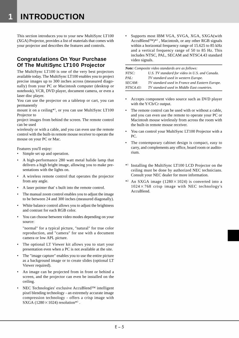
11 Laser ButtonPress and hold this button to activate the laser pointer. Whenlit, you can use the laser to draw your audience's attention toa red dot that you can place on any object within 10 m.
12 Mouse Pointer ButtonsWorks as a mouse for your computer. This button is alsoused to adjust screen position. Push (+) or (–) to select thesubmenu you want to adjust.
13 Right Click ButtonPress this button to exit "Menus" or "Position."
14 Freeze ButtonThis button will freeze a video image. Press again toresume motion.
15 Position ButtonWhen image is magnified, press this button to activate themouse. This allows you to select the portion of the imagedisplayed on screen. Position button will remain lit for 10seconds or until right click button is pushed.
Note: When you are adjusting Position, the Mouse Pointerbutton is used to move the picture.
16 Picture Mute ButtonThis button turns off the image for a short period of time.Press again to restore the image.
17 Magnify ButtonUse the (+) or (–) button to adjust the image size up to400%.
18 Slide ButtonPress (+) to advance the next file or slide and (-) to returnto the previous file or slide. (the optional LT Viewerboard required)
19 Volume ButtonsPress (+) to increase the volume and (–) to decrease it.
20 Remote JackConnect your remote control cable here for wired opera-tion.
Note: You cannot use Menu and Position at the same time.
Remote Control Precautions• Do not look into the laser pointer while it is on.• Do not point the laser beam at a person.• Handle the remote control carefully.• If the remote control gets wet, wipe it dry immediately.• Avoid excessive heat and humidity.• If you will not be using the remote control for a long
time, remove the batteries.• Do not mix new and old or different types of batteries.
16
15
13
14
11
12
18
17 19
MAGNIFYSLIDE
VOLUME
POSITION
FREEZE
PIC-MUTE
OFVIDEO
MENU
LASER
R-CLICK
RGBPC CARD
S-VI
+- +
-
+-
+
-
20

E – 13
This section describes how to set up your MultiSync LT100projector and how to connect video and audio sources.
Setting Up Your MultiSync LT100ProjectorYour MultiSync LT100 Projector is simple to set up and use.But before you get started, you must first:
1. Determine the image size
2. Set up a screen or select a non-glossy white wall ontowhich you can project your image.
Carrying The Projector Always carry your projector by thehandle. Ensure that the power cord and any other cablesconnecting to video sources are disconnected before mov-ing the projector. When moving the projector or when it isnot in use, cover the lens with the lens cap.
Selecting A Location The further your projector is from thescreen or wall, the larger the image. The minimum size theimage can be is approximately 24" (0.61 m) measureddiagonally when the projector is roughly 1.2 m from thewall or screen. The largest the image can be is 300" (7.6 m)when the projector is about 12.3 m from the wall or screen.
INSTALLATION2
300
240
200
160
120100806040200
Projection Distance
Dia
gona
l Im
age
Siz
e (in
ch)
Projection Distance and Image Size
300”
231”
27”
24”
Width
Height Screen size(diagonal)
Projection distance
MEMU
SELECT
ENTER
STATUS
POWER
ON / OFF
AC IN
Carrying handlePull it out ; push it back to retract.
TELE
WIDE
0.0 1 2 3 4 5 6 7 8 9 10 11 12 (m)
E – 14
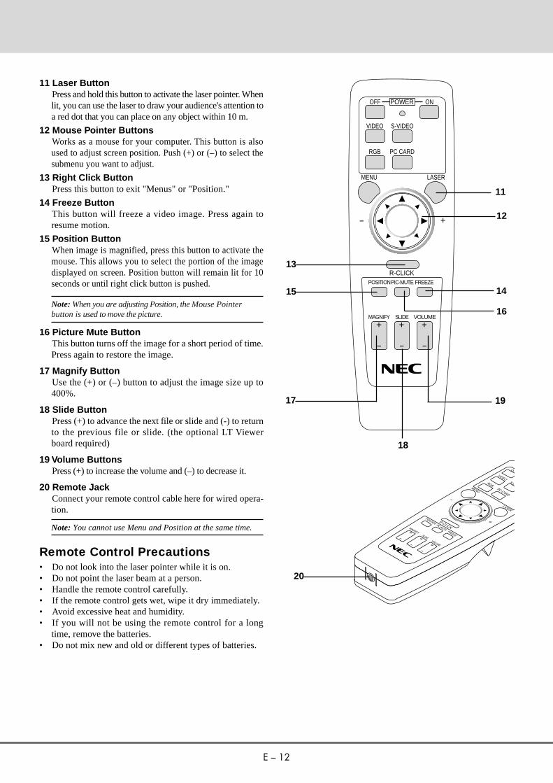
Wide
Screen size
Projection angle α
Screen width H
A
B
Projection distance C
D
E
inch
Degree
inch
mm
mm
mm
mm
mm
mm
40” 60” 70” 80” 90” 100” 120” 150” 180” 200” 240” 270” 300”
14.8 14.8 14.7 14.7 14.6 14.6 14.6 14.6 14.5 14.5 14.5 14.5 14.5
32 48 56 64 72 80 96 120 144 160 192 216 240
813 1219 1422 1626 1829 2032 2438 3048 3658 4064 4877 5486 6096
1655 2483 2915 3342 3767 4185 5042 6316 7591 8441 10140 11415 12704
119 178 207 237 267 296 356 444 533 593 711 800 889
1600 2400 2819 3233 3645 4049 4879 6114 7348 8171 9817 11052 12301
305 457 533 610 686 762 914 1143 1372 1524 1829 2057 2286
610 914 1067 1219 1372 1524 1829 2286 2743 3048 3658 4115 4572
Tele
* For Screen Sizes of 24 to 300 inches not indicated on the projection tables, use the formulas on the next page.
40” 60” 70” 80” 90” 100” 120” 150” 180” 200” 240” 270” 300”
11.4 11.4 11.4 11.4 11.3 11.3 11.3 11.3 11.3 11.3 11.2 11.2 –
32 48 56 64 72 80 96 120 144 160 192 216 –
813 1219 1422 1626 1829 2032 2438 3048 3658 4064 4877 5486 –
2143 3213 3739 4286 4847 5406 6483 8117 9753 10829 13024 14660 –
119 178 207 237 267 296 356 444 533 593 711 800 –
2101 3150 3665 4201 4752 5301 6358 7960 9566 10620 12774 14379 –
305 457 533 610 686 762 914 1143 1372 1524 1829 2057 –
610 914 1067 1219 1372 1524 1829 2286 2743 3048 3658 4115 –
Screen size
Projection angle α
Screen width H
A
B
Projection distance C
D
E
inch
Degree
inch
mm
mm
mm
mm
mm
mm
Projection Distance
E – 15
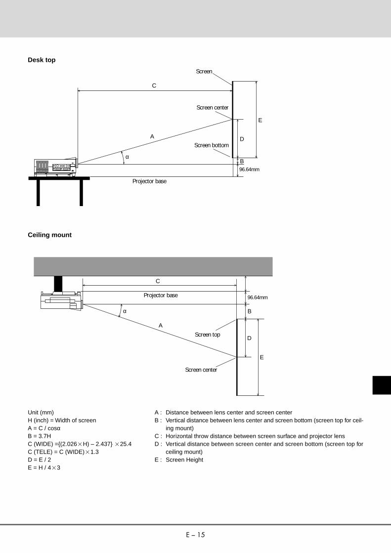
Desk top
Ceiling mount
C
A
Screen center
D
E
B96.64mm
Projector base
α
Projector base
C
α
D
E
B
A
Unit (mm)H (inch) = Width of screenA = C / cosαB = 3.7HC (WIDE) ={(2.0262H) – 2.437} 225.4C (TELE) = C (WIDE)21.3D = E / 2E = H / 423
Screen
Screen bottom
96.64mm
Screen center
Screen top
A : Distance between lens center and screen centerB : Vertical distance between lens center and screen bottom (screen top for ceil-
ing mount)C : Horizontal throw distance between screen surface and projector lensD : Vertical distance between screen center and screen bottom (screen top for
ceiling mount)E : Screen Height
E – 16
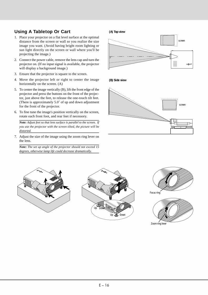
Using A Tabletop Or Cart1. Place your projector on a flat level surface at the optimal
distance from the screen or wall so you realize the sizeimage you want. (Avoid having bright room lighting orsun light directly on the screen or wall where you'll beprojecting the image.)
2. Connect the power cable, remove the lens cap and turn theprojector on. (If no input signal is available, the projectorwill display a background image.)
3. Ensure that the projector is square to the screen.
4. Move the projector left or right to center the imagehorizontally on the screen. (A)
5. To center the image vertically (B), lift the front edge of theprojector and press the buttons on the front of the projec-tor, just above the feet, to release the one-touch tilt feet.(There is approximately 5.0˚ of up and down adjustmentfor the front of the projector.
6. To fine tune the image's position vertically on the screen,rotate each front foot, and rear feet if necessory.
Note: Adjust feet so that lens surface is parallel to the screen. Ifyou use the projector with the screen tilted, the picture will bedistorted.
7. Adjust the size of the image using the zoom ring lever onthe lens.
Note: The set up angle of the projector should not exceed 15degrees, otherwise lamp life could decrease dramatically.
(A) Top view
(B) Side view
screen
screen
Focus ring
Zoom ring lever
Up Down
Up Down

E – 17
ME
MUSE
LEC
T
EN
TER
STA
TUS
PO
WE
RO
N / OFF
AC
IN
2
1
Projector
Zipper
Note book PC
Other Accessories
Transporting and storing theprojectorA padded carrying case has been supplied with your projec-tor. Please use this case when transporting and storing theprojector. The carrying case also has a compartment for yourlaptop computer.To use the carrying case follow the directions below:1. Unfold carrying case.
2. Zip up the sides of the case.
3. Hold the projector by it’s handle and slide it into the largecompartment of the carrying case.
5. Unlatch the belt and then place your notebook computerinto the front pouch.
6. Latch the belt.
7. Store the remote control and other accessories in the sidepouches on the carrying case.
2
1
When storing the remote control, place the remote in its protective case. Thecase will keep the remote buttons from being accidentally pushed while it isbeing stored or transported. This will keep the batteries from being dis-charged.
4. Zip up the top of the case.
* Carry the projector carefully. Bumping or dropping theprojector may cause damage.
E – 18
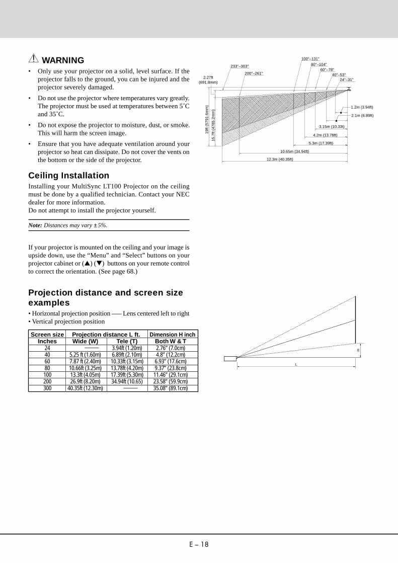
WARNING• Only use your projector on a solid, level surface. If the
projector falls to the ground, you can be injured and theprojector severely damaged.
• Do not use the projector where temperatures vary greatly.The projector must be used at temperatures between 5˚Cand 35˚C.
• Do not expose the projector to moisture, dust, or smoke.This will harm the screen image.
• Ensure that you have adequate ventilation around yourprojector so heat can dissipate. Do not cover the vents onthe bottom or the side of the projector.
Ceiling InstallationInstalling your MultiSync LT100 Projector on the ceilingmust be done by a qualified technician. Contact your NECdealer for more information.Do not attempt to install the projector yourself.
Note: Distances may vary ±5%.
If your projector is mounted on the ceiling and your image isupside down, use the “Menu” and “Select” buttons on yourprojector cabinet or (▲) (▼) buttons on your remote controlto correct the orientation. (See page 68.)
Projection distance and screen sizeexamples• Horizontal projection position ––– Lens centered left to right• Vertical projection position
233"–303"
200"–261"
100"–131"
80"–104"60"–78"
40"–53"24"–31"
1.2m (3.94ft)
2.1m (6.89ft)
3.15m (10.33t)
4.2m (13.78ft)
5.3m (17.39ft)
10.65m (34.94ft)
12.3m (40.35ft)
19ft
(579
1.6m
m)
15.7
ft (4
785.
2mm
)
2.27ft(691.8mm)
L
H
Screen size Projection distance L ft. Dimension H inchInches Wide (W) Tele (T) Both W & T
24 3.94ft (1.20m) 2.76” (7.0cm)40 5.25 ft (1.60m) 6.89ft (2.10m) 4.8” (12.2cm)60 7.87 ft (2.40m) 10.33ft (3.15m) 6.93” (17.6cm)80 10.66ft (3.25m) 13.78ft (4.20m) 9.37” (23.8cm)100 13.3ft (4.05m) 17.39ft (5.30m) 11.46” (29.1cm)200 26.9ft (8.20m) 34.94ft (10.65) 23.58” (59.9cm)300 40.35ft (12.30m) 35.08” (89.1cm)

E – 19
PC CONTROLVIDEO INPUT
RGB INPUT RGB OUTPUTS-VIDEO VIDEO L(MONO)-R-AUDIO
OUTPUT
INTPUT
RGB RGBAUDIO AUDIOREMOTECONTROL
Document Camera
VCR, Laser Disk Player or DVD Player
Wiring Diagram
To video, S-video, and audioinputs on the projector
IBM VGA or Compatibles Macintosh or Compatibles (Desk top type)
Remote MouseReceiver
PS/2 mouse adapter(supplied)
Mac ADB adapter(supplied)
Pin adapter for Macintosh(supplied)
DVD Player with Y/Cb/Cr output
Signal cable (supplied)To mini D-Sub 15-pin connector on the Projector
Remote MouseReceiver
Remote Control Guideline1. Plug the serial cable with the remote mouse receiver into your computer's mouse port and restart your computer to gain
remote mouse control.2. When using the remote control's built-in infrared mouse on a laptop computer, the laptop's mouse, trackball or trackpad will
be disabled. Disconnect the infrared receiver and restart your computer to regain trackball or trackpad mouse control.3. If the screen goes blank while using your remote control, it may be the result of the computer's screen-saver or power
management software. If you accidentally hit the OFF button on the remote control, wait one full minute and then press theON button to resume.
To RGB input on the projector

E – 20
Connecting Your PC Or MacintoshComputerConnecting your PC or Macintosh computer to yourMultiSync LT100 (XGA) Projector will enable you to projectyour computer's screen image for an impressive presentation.All of these following display standards are supported:
To connect to a PC, Macintosh or computer equipped with anXGA/SVGA/VGA adapter or compatible graphics adapter,simply:
1. Turn off the power to your projector and computer.
2. If your PC does not support XGA/SVGA/VGA you willneed to install an XGA/SVGA/VGA graphics board.Consult your computer's owner's manual for your XGA/SVGA/VGA configuration. If you need to install a newboard, see the manual that comes with your new graphicsboard for installation instructions.
3. Use the signal cable that's supplied to connect your PC orMacintosh computer to the projector. For Macintosh, usethe supplied pin adapter to connect to your computer'svideo port.
4. Turn on the projector and the computer.
5. If the projector goes blank after a period of inactivity, itmay be caused by a screen saver installed on the com-puter you've connected to the projector.
Settings for Macintosh adapter
Macintosh models applied
Desktop type and PowerBook with 8002600LCD panel
PowerBook with 6402480 LCD panel
Desktop type with AccuBlend
Setting required to be selected resolution onMac after restarting.
Set to VGA/SVGA (8002600)
Set to 17” multi-scan mode (6402480)
Set to 17” multi-scan mode (10242768)
Setting Mode (Fixed resolution)
16” fixed mode (output is 8322624)
13” fixed mode (output is 6402480)
19” fixed mode (output is 10242768)
When using a Macintosh with the LT100, set the DIP switchof the supplied pin adapter according to your resolution.After setting, restart your Macintosh.See the following pages for setting of the DIP switch.• When using with a Macintosh, XGA (10242768) is
recommended if your Macintosh supports this mode.
• When using with a Macintosh PowerBook, output maynot be set to 8002600 unless “mirroring” is off on yourPowerBook. Refer to owner’s manual supplied with yourMacintosh computer for mirroring.
Note: A Video Adapter cable manufactured by Apple Computeris needed for a PowerBook which does not have a mini D-Sub15-pin connector.
VGA 6402480 for graphics VGA 6402400 for graphicsVGA 6402350 for graphics VGA 7202400 for textVGA 7202350 for text SuperVGA 8002600Macintosh at 6402480 Macintosh at 8322624XGA10242768 Macintosh at 10242768SXGA128021024 (AccuBlend)

E – 21
Settings for Monitor Mode
Number of DIP switch
Monitor size
15” multi-scan mode /16”–13”
17” multi-scan mode /19”–13”
19” multi-scan mode /21”–13”
13” fixed mode /6402480
VGA/SVGA mode
16” fixed mode /8322624
19” fixed mode /10242768
S1
ON
ON
ON
ON
S2 S3 S4
ON
S5
ON
ON
S6
ON
S7
ON
S8
ON
Note: For setting other than display modes supported by your Macintosh and LT100, using of the DIPswitch may bounce a image slightly or may display nothing. If this happens, set the DIP switch to the 13”fixed mode and then restart your Macintosh. After that, restore to a displayable mode and then restart theMacintosh again.
Make sure that LT100 and your Macintosh are connected with the pin adapter and the supplied signalcable (mini D-Sub 15-pin connector) and then restart your Macintosh.
Note: Refer to your computer's owner's manual for more information about your computer's video outputrequirements and any special identification or configuring your projector's image and monitor mayrequire.
ONON
→
1 2 3 4 5 6 7 8
ON
→
1 2 3 4 5 6 7 8
19” fixed mode17” multi-scan mode VGA/SVGA mode
Examples of DIP switch setting
→
1 2 3 4 5 6 7 8

E – 22
Changing Video ResolutionsDepending on your computer's graphic capability, you maybe able to select one of several resolutions. Generally acomputer- either a PC or Macintosh- with 1 meg. of memorywill run:
6402480 at 16.7 million colors (24 bit Truecolor)8002600 at 65 thousand colors.10242768 at 256 colors.
As the resolution increases, the number of colors you can rundecreases. With 2 meg. of memory a computer will run:
6402480 at 16.7 million colors (24 bit Truecolor).8002600 at 16.7 million colors (24 bit Truecolor).10242768 at 65 thousand colors.128021024 at 256 colors.
Windows 95There are two methods you can use to change your resolu-tion.
Method 11. Move your cursor to the background image and click.
2. In the "Properties" menu, select "Settings."
3. Change your resolution and click "OK."
4. You may be asked to reboot for the changes to take effect, oryou' ll get a message that "Windows is about to resize yourdisplay." When asked if you want to keep your settings,select "Yes."
Method 21. Click on your "My Computer" icon.
2. Open "Control Panel" and select "Display."
3. Change your resolution and click "OK." after the new reso-lution is selected.
4. You may be asked to reboot for the changes to take effect, oryou' ll get a message that "Windows is about to resize yourdisplay." When asked if you want to keep your settings,select "Yes."
Windows 3.11. Click on the "Main" icon and open "Control Panel."
2. Select "Change System Settings" and click on "Option."
3. Choose "Change Display Settings."
4. Select the resolution you want.
5. Choose the current drive or another.
6. Restart Windows for the changes to take effect.
Macintosh1. Under the Apple menu, select "Control Panels" and open
"Monitors."
2. Click and open "Options."
3. Select your new resolution and click "OK."
If you have an NEC monitor connected to your Macintosh,you may have a "DPI-On-The-Fly" extension that enables youto change your resolution directly. The "DPI-On-The-Fly" iconis under your Apple menu.

E – 23
Connecting Your DVD PlayerYou can connect your MultiSync LT100 Projector to a DVDplayer with the component outputs or Video output. To do so,simply:1. Turn off the power to your projector and DVD player.
2. If your DVD player has the component video (Y,Cb,Cr)output use the optional 15-pin-to-RCA23 cable to con-nect your DVD player to the RGB INPUT connector onthe LT100.
For a DVD player without component video (Y,Cb,Cr)outputs, use common RCA cables (not provided) to con-nect a composite VIDEO output of the DVD player to theVideo Input of the LT100.
3. Turn on the projector and the DVD player.
Note: Refer to your DVD player's owner's manual for moreinformation about your DVD player's video output requirements.
Connecting Your Document CameraYou can connect your MultiSync LT100 Projector to a docu-ment camera. To do so, simply:
1. Turn off the power to your projector and document cam-era.
2. Use a standard video cable to connect your documentcamera to the Video input on your projector.
3. Turn on the projector and the document camera.
Note: Refer to your document camera's owner's manual for moreinformation about your camera's video output requirements.
Connecting Your VCR Or Laser DiscPlayerUse common RCA cables (not provided) to connect yourVCR or laser disc player to your MultiSync LT100 Projector.To make these connections, simply:1. Turn off the power to your projector and VCR or laser disc
player.
2. Connect one end of your RCA cable to the video outputconnector on the back of your VCR, or laser disc player,connect the other end to the Video input on your projector.Use standard RCA audio patch cords to connect the audiofrom your VCR, or laser disc player to your projector (ifyour VCR, or laser disc player has this capability). Becareful to keep your right and left channel connectionscorrect for stereo sound.
3. Turn on the projector and the VCR, or laser disc player.
Note: Refer to your VCR, or laser disc player owner's manual formore information about your equipment's video output require-ments.
Connecting An External MonitorYou can connect a separate, external monitor to your projec-tor to simultaneously view on a monitor the image you'reprojecting. To do so:
1. Turn off the power to your projector and computer, docu-ment camera or video source.
2. Use a 15-pin cable to connect your monitor to the RGBOUTPUT connector on your LT100 projector.
3. Turn on the projector and the computer, document cameraor video source.

E – 24
Connecting Your Remote MouseReceiverThe remote mouse receiver enables you to operate yourcomputer's mouse functions from the NEC MultiSync LT100remote control. It is a great convenience for clicking throughyour computer-generated presentations.
To connect the remote mouse receiver:1. Turn off your computer.
2. For PCs: Remove your current mouse and connect theserial cable from the remote mouse receiver to your PC'smouse port. (Use the 6-pin adapter for connecting to a PS/2 computer.)
For Macintosh: Remove your current mouse from yourcomputer, attach the Macintosh adapter to the remotemouse receiver's serial cable, and connect the receiver toyour mouse port.
3. When the remote mouse receiver is installed, it willdisable your regular mouse, disconnect the remote mousereceiver and restart your computer.
IBM PC/AT
IBM PS/2
Macintosh
Input for wired remote control
Input for wired remote control
E – 25
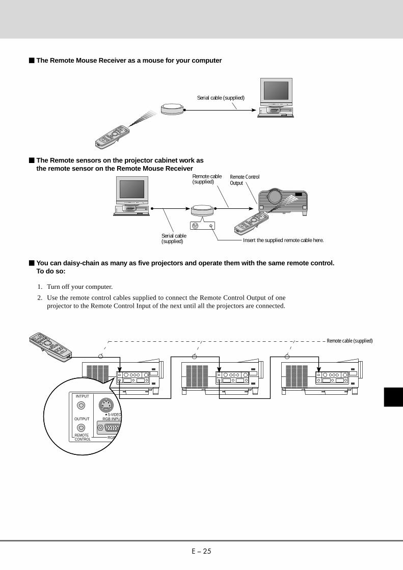
m The Remote Mouse Receiver as a mouse for your computer
m The Remote sensors on the projector cabinet work asthe remote sensor on the Remote Mouse Receiver
m You can daisy-chain as many as five projectors and operate them with the same remote control.To do so:
1. Turn off your computer.
2. Use the remote control cables supplied to connect the Remote Control Output of oneprojector to the Remote Control Input of the next until all the projectors are connected.
RGB INPUTS-VIDEO
OUTPUT
INTPUT
RGBREMOTECONTROL
Remote cable (supplied)
Serial cable (supplied)
Serial cable(supplied)
Remote cable(supplied)
Remote ControlOutput
Insert the supplied remote cable here.

E – 26
This section describes how to select a computer or videosource and how to adjust the picture and sound.
General ControlsBefore you turn on your MultiSync LT100 Projector, ensurethat the computer or video source is turned on and that yourlens cap is removed.
1. Turn On The Projector
The main power switch is on the back panel of theMultiSync LT100 Projector. By turning this switch on,the projector will go into its standby mode and the powerlight will glow amber. Only after you press the "On"button on the remote control or projector cabinet will thepower light turn to green and the projector become readyto use.
Note: To turn the projector on and off with just the backpanel switch, use the menu and enable the "auto start"feature. (See page E-31. )
2. Select The Computer Or Video Source
Press the "Video" (VCR, DVD player, document camera,or laser disc player), "S-video", "RGB" (computer), or"PC Card" button on the remote control to display theimage. Or press the "Menu" button on the cabinet and usethe icons to select your video source: "Video", "S-Video","RGB" or "PC Card".
3. Adjust The Image Size
Adjust the size of the screen with the zoom ring lever onthe projector.
4. Focus
Adjust the focus with the focus ring on the projector.
5. Turning Off The Projector
First press the "off" button on the remote control or pressand hold down the "on/off" button on the cabinet for onesecond. The power light will glow amber. Then turn offthe main power switch on the back panel. The power lightwill go out.
IMPORTANT:• The projector should be unplugged if it will not to be used
for an extended period.
• To turn off the image briefly (five minutes or less), use the"Picture Mute" button instead of turning the projector offand on.
• The projector will display a black, blue image or focuspattern if no input signal is present.
• Do not turn the projector off and then immediately backon. The projector needs to cool for a minute before it canbe restarted.
OPERATION3

E – 27
Using The Menus1. Press the "Menu" button on the remote control or projector cabinet to display the Main Menu.
2. Press the "Select" button on the projector cabinet or (▲) (▼) buttons on your remote control to highlight the menu for theitem you want to adjust.
3. Press the "Enter" button on the projector cabinet or the "Left Click" button on the remote control to select a submenu or item.
4. Adjust the level or turn the selected item "on" or "off" by using the "Adjust" (+) or (–) buttons on the remote control or cabinet. Theon-screen gauge will display your changes. The (+) button is "on" and (–) is "off".
5. The change is stored until you adjust it again.
6. Repeat steps 2-5 to adjust an additional item, or press “Right-Click” on your remote control to quit the menu display.
VIDEO/ S-VIDEO RGB YCbCr
Note: The following explains conditions that you will encounter when operating your LT100 while displaying an SXGA (128021024) image.When a menu or message is displayed while an SXGA image is projected, several lines of information will be lost.When the "LAMP USAGE 1000 HOURS" message appears, several lines of information will be lost.The "LAMP USAGE 1000 HOURS" message will not appear when the freeze button is activated.SXGA images inherently display a 5 to 4 ratio, resulting in an image that appears to be smaller and more square than the 4 to 3 format commonlydisplayed.

E – 28
Enables you to select a video source such as a VCR, DVD player, laser disk player, compu-ter or document camera depending on what is connected to your inputs. Press the "Select"button on the projector cabinet or (▲) (▼) buttons on your remote control to highlight themenu for the item you want to adjust.
VideoSelects device connected to your video input (VCR, document camera, laser disk player orDVD player).
S-VideoSelects device connected to S-Video input (Laser disk player, S-VHS VCR or DVD player).
RGBSelects computer connected to your RGB input. Use the "Adjust" (+) or (–) buttons toselect a standard* or one of five custom settings you can create and store. Press the "Enter"button on the cabinet or the "Left Click" button on the remote control to save your selection.
Note: If a previously saved custom memory location is used with a new or different input signal itmay not sync up, producing a distorted image, or no image at all. If so, follow the instructionsbelow: 1) Disconnect the signal cable so that there is no input signal. In this condition the on-screen
message will be displayed.2) Select RGB standard from the source menu.3) Connect the signal cable again.
Note: * Standard is normally used and it can be user changed and automatically recalled.
PC CARDThis feature enables you to make a presentation using the Viewer function with the optionalLT Viewer board (VK-LT) installed.Press the Mouse pad (+) or (-) buttons to select "START" for the image you want to displayfirst and "SELECT FILE" for the file you want to select or "Select Slide" for the image youwant to slide.
Menu Descriptions & FunctionsSource Menu

E – 29
Image Adjustment Menu
Provides access to controls for your image and sound. Use the “Select” button on the projector cabi-net or (▲) (▼) buttons on your remote control to highlight the menu for the item you want to adjust.The volume, image mode, brightness, contrast, color, tint, sharpness and white balance controls areavailable for Video or S-Video sources.The volume, image mode, brightness, contrast, horizontal position, vertical position, white balance,alignment and auto picture controls are available for RGB source.
VolumeUse the “Adjust” (+) or (–) buttons to adjust the volume.
Image ModeUse the "Select" button on the projector cabinet or (▲) (▼) buttons on your remote control to selectthe item you want to adjust.
Note: Input and Display modes are not available for PC CARD.
Gamma ............. Use the mouse pad (+) or (–) buttons to choose "Normal" when in a lighted roomand "Natural 1&2" when in a darkened room. "Natural 1" for better flesh tone;"Natural 2" for true reproduction of middle tones.
Input Mode ....... Use the mouse pad (+) or (–) buttons to choose "DOC CAM" for a document cam-era or other low APL input, "Standard Video" for a regular video picture such asNTSC, "RGB Signal" for an RGB source such as a computer, or "Y/Cb/Cr Signal"for a component video source such as a DVD player.
Display Mode ... Use the mouse pad (+) or (–) buttons to choose "Normal Aspect" for normal videopicture with a 4-to-3 aspect ratio and "Wide Aspect" for DVD's with a 16-to-9aspect ratio.
Note:1) Flicker may appear on a freeze-frame picture with a Video or S-Video source. If this happens, select the
Document Camera mode using the Image mode icon on the Image Adjustment Menu, and then adjust thecontrast and other items for an optimal image.
2) A frame may freeze for a brief period of time when a video is played back in fast-forward or fast-rewind witha Video or S-Video source. If this happens, select the Natural mode (for cinema) using the Image Mode iconon the Image Adjustment Menu.

E – 30
RGB AUTO PICTURE ON
RGB AUTO PICTURE OFF
BrightnessUse the “Adjust” (+) or (–) buttons to adjust the brightness.
ContrastUse the “Adjust” (+) or (–) buttons to adjust the contrast.
Color* Use the “Adjust” (+) or (–) buttons to adjust the color.
Tint*Use the “Adjust” (+) or (–) buttons to adjust the tint.
Sharpness*Use the “Adjust” (+) or (–) buttons to adjust the sharpness.
White BalanceUse the Mouse pad (+) or (–) buttons to adjust the white balance.For Video/RGB .................. Brightness for each color (RGB) is used to adjust the black level of the
screen; Contrast for each color (RGB) to adjust the white level of thescreen.
For Y/Cb/Cr ....................... Brightness for each color (Y/Cb/Cr) is used to adjust the white level ofthe screen; Contrast for each color (Y/Cb/Cr) to adjust the black level ofthe screen.
AlignmentUse the Mouse pad (+) or (–) buttons to adjust the horizontal and vertical position, "Picture", and"Fine Picture".Horizontal Position** .......... Use the “Adjust” (+) button to move the image right; (–) to move it left.Vertical Position** .............. Use the “Adjust” (+) button to move the image up; (–) to move it down.
Auto Picture**Use the “Adjust” (+) button to turn this feature on so “Picture” and “Fine Picture” adjustments aremade automatically. Use the “Adjust” (–) button to turn this feature off so you can make “Picture andFine Picture” adjustments manually.
Picture Adjustment**(when AUTO PICTURE is off)Use this icon with the “Fine Picture Adjustment” to fine tune the computer image or to remove anyvertical banding that might appear. This function adjusts the clock frequencies to eliminate the verticalbanding in the image. Press the “Adjust” (+) and (–) buttons until the banding disappears. This adjust-ment may be necessary when you connect your computer for the first time. This adjustment is madeautomatically when the Auto Picture is turned on.
Fine Picture ..(when AUTO PICTURE is off)Use this icon to adjust the clock phase or to reduce video noise, dot interference or cross talk. (This isevident when part of your image appears to be shimmering.) Use the “Adjust” (+) and (–) buttons toadjust the image. Use the Fine Adjustment only after the Picture Adjustment is complete. This adjust-ment is made automatically when the Auto Picture is turned on.
Note:* Color, Tint, and Sharpness controls will not work with an RGB source. The Tint control will not work
with a PAL or SECAM source. The Color and Tint controls will work with a Y/Cb/Cr source.** Alignment controls such as Horizontal and Vertical position controls, and Picture, Fine Picture and
Auto Picture adjustments will not work with a Video or S-Video source.
E – 31
Provides access to Lamp Usage information, the Auto Start, Power Management and On-screen Mute features. Use the “Select” button on the projector cabinet or (▲) (▼) buttons onyour remote control to access a submenu. Then press “Adjust” (+) or (–) to choose a specificoption.
Lamp UsageThis tells you how long the lamp has been in operation. It is recommended that you replace alamp after 1000 hours of service. After you install a new lamp, select this icon and press andhold the “Power On” button on the remote control for ten seconds to reset the lamp clock backto zero.
Note: The projector will turn off and go into stand by mode after 1100 hours of service. If thishappens, press the "Power Off" button on the remote control for ten seconds to reset the lamp clockback to zero. Do this only after replacing the lamp.
Auto StartTurns the projector on automatically when the main power switch is turned on. This elimi-nates the need to always use the “Power” button on the remote control or projector cabinet.Press (+) to turn this feature on and (–) to turn it off.
Power ManagementWhen “Power Off” is on and there is no video input for five minutes or more, the projectorwill automatically turn itself off. Press the (+) to turn this feature on and (–) to turn it off.
On Screen MuteUse the mouse pad (+) button to turn off the On Screen Mute ; (–) to restore it.The On screen Mute feature keeps the menu from displaying when the projector is turned onor when switching inputs.
Power Menu
E – 32
Settings Menu Enables you to set preferences and other operating options. Use the “Select” button on the projectorcabinet or (▲) (▼) buttons on your remote control to access the submenu you want.
Custom Memory This enables you to save your current settings for an RGB source in one of five memories, Custom 1-5.To change the STANDARD settings, proceed as follows:1. Connect your computer to the MultSync LT100.2. Select the "STANDARD" in RGB source.3. Adjust the horizontal/vertical position, Picture, and Fine Picture adjustments.4. Select the Custom Memory icon.5. Press the "Adjust" (+) or (–) buttons to choose a memory location, then press "Enter" on the cabinet
or the "Left Click" on your remote control to save the new settings.If you do not want to change the STANDARD settings, first selct the Custom Memory icon, then dothe same as step 5.
Capture (with the optional viewer board installed only)When the Capture is selected, press "Enter" on the projector cabinet or Left Click button on theremote control to display "Execute" and "capture" an image from a source that is currently beingdisplayed.When capturing is completed, "Completed" is displayed under the Capture icon.Unless a flash memory card is inserted into the slot of the viewer board, "No Card" is displayed. Thismeans that the Capture feature is not available. The "Card Error" display means that the free space ofthe flash memory card is insufficient for saving images. Make more space available on the card byerasing unwanted images with your PC. The number of images that can be captured depends on thesize of the flash memory card.
Note: Be sure not to turn off the power or remove the flash memory card unless "Completed" is displayed.Doing so could cause a loss of the data in the flash memory card or damage to the card itself.
BackgroundUse this feature to display a black, blue screen or focus pattern when no signal is available. Press themouse pad (+) or (-) buttons to choose the back screen you want. Press "Enter" on the cabinet or the"Left Click" on your remote control to save your change.
ProjectionThis reorients your image based upon projector location. Press the “Adjust” (+) or (–) button until itis correct. Press “Enter” on the cabinet or the “Left Click” on your remote control to save yourchange. The options are: front floor projection, rear ceiling projection, rear floor projection, and frontceiling projection.
LanguageUse the “Adjust” (+) or (–) to choose one of six languages for on-screen instructions. Press “Enter”on the cabinet or the “Left Click” on your remote control to save your change. The options are:English, German, French, Italian, Spanish and Swedish.
ResetChanges all adjustments to the factory preset levels for each source individually. To activate, you musthold down the “Adjust” (+) button on the cabinet or remote control for at least two seconds. The adjust-ments that will be reset are horizontal and vertical control, picture and fine picture adjustment (for thecurrent source only), brightness, contrast, color, tint, and sharpness.When custom setting is selected, reset changes all adjustments to the factory preset levels of thecurrent input signal for selected custom memory location. This will not return to your previous cus-tom setting and will delete your saved settings from custom memory.
E – 33
Using the Viewer functionIf you use the Viewer function on the projector, you must firstinstall the optional LT Viewer board (VK-LT) in the projectorand set up the exclusive software included with the VK-LTkit.See the user's manual included with the VK-LT for installingand uninstalling the software.
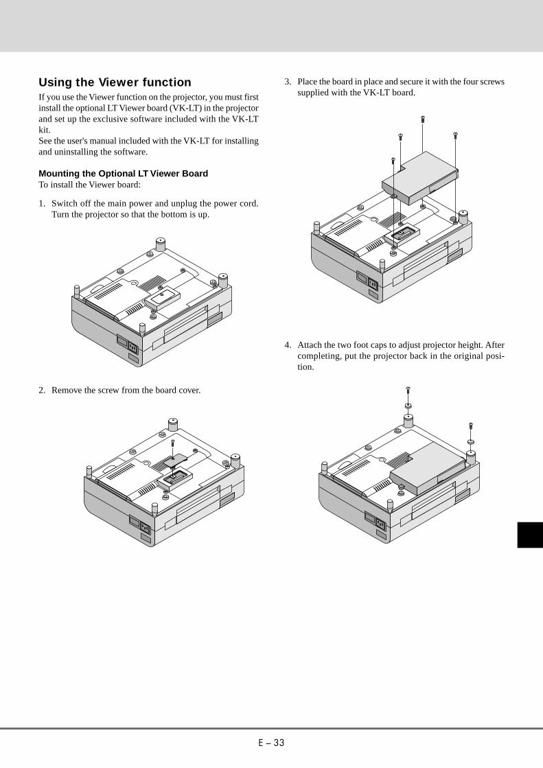
Mounting the Optional LT Viewer BoardTo install the Viewer board:
1. Switch off the main power and unplug the power cord.Turn the projector so that the bottom is up.
2. Remove the screw from the board cover.
3. Place the board in place and secure it with the four screwssupplied with the VK-LT board.
4. Attach the two foot caps to adjust projector height. Aftercompleting, put the projector back in the original posi-tion.

E – 34
Projecting SlidesOrientation of flash memory card insertionThe flash memory card has a front and a back side and theflash memory card is designed to be inserted in only one ori-entation. The card is designed so that it cannot be inserted inreverse. Trying to force the card into slot may result in dam-age to the card and the PCMCIA card slot. See the flashmemory card manual for information about the orientation ofthe flash memory card.
PCMC IA-ATA
Flash Memory Card
* The type of flash memory card required for use in the pro-jector is a Type II PCMCIA-ATA flash memory card. Neveruse a different type of card, doing so may result in damageto the card or PC card slot.
To Project the Slides (the presentation materials)1. Insert a flash memory card into the PC card slot.
* To eject the flash memory card, press the Eject button.
Note: Should the card be difficult to insert, do not forcefullypush the card in.
2. Select the PC card as a source.
* Press the Menu button on the remote control or projec-tor cabinet and select "PC CARD" from the Sourcemenu.
* If there is no flash memory card in the card slot, theprojector displays a blue back or black back image.
3. Select "Select File" or "Select Slide".
* Use the mouse pad (+) or (-) button on the remote con-trol to select "Select File" or "Select Slide".
4. Select a file or a slide.
Use the mouse pad (+) or (–) button on the remote controlto select the file or slide you want to display and press theEnter button on the cabinet or the Left Click button on theremote control. See the following pages for more details.
75 631 2 FileFile File
FileFile File
Multi Cursor
File
HGE FDCA B presentation presentationpresentation presentation
presentation presentationpresentation presentation
Table Cursor
* The selected file or slide will be displayed.
Note: If you select "Start" and press the Enter button on thecabinet or the Left Click button on the remote control, the slideswill be looped. To use the Start feature, you must first set on thesoftware included with the LT Viewer board.
Note: The mouse pad (+) or (–) button is valid only when theMenu button is lit.
E – 35
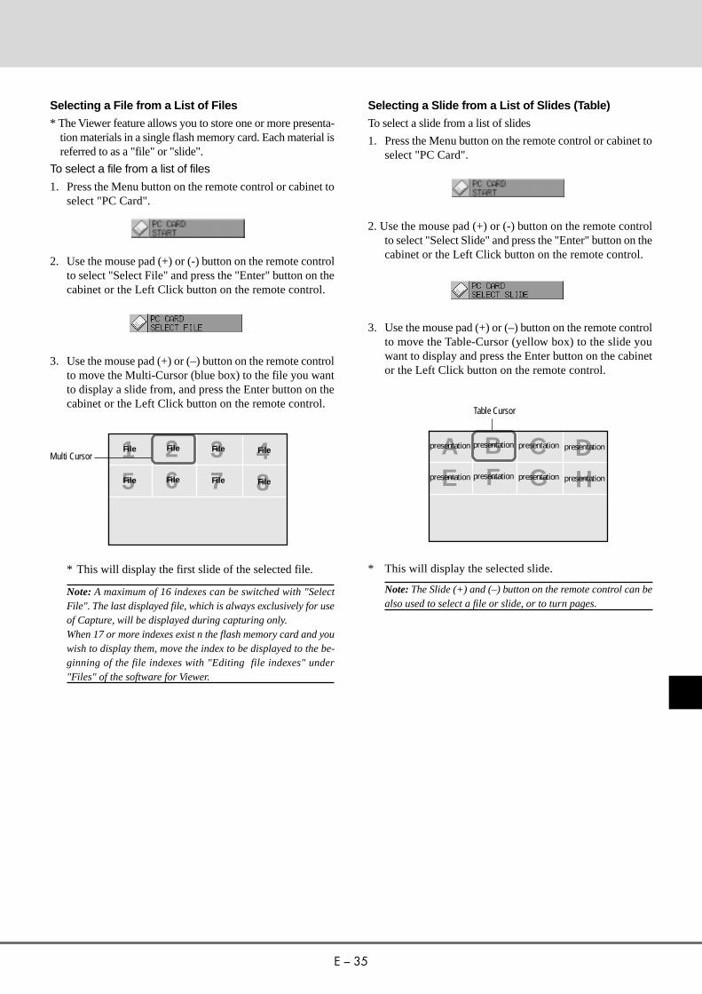
Selecting a File from a List of Files
* The Viewer feature allows you to store one or more presenta-tion materials in a single flash memory card. Each material isreferred to as a "file" or "slide".
To select a file from a list of files
1. Press the Menu button on the remote control or cabinet toselect "PC Card".
875 6431 2 File FileFile File
File FileFile File
Multi Cursor
2. Use the mouse pad (+) or (-) button on the remote controlto select "Select File" and press the "Enter" button on thecabinet or the Left Click button on the remote control.
3. Use the mouse pad (+) or (–) button on the remote controlto move the Multi-Cursor (blue box) to the file you wantto display a slide from, and press the Enter button on thecabinet or the Left Click button on the remote control.
* This will display the first slide of the selected file.
Note: A maximum of 16 indexes can be switched with "SelectFile". The last displayed file, which is always exclusively for useof Capture, will be displayed during capturing only.When 17 or more indexes exist n the flash memory card and youwish to display them, move the index to be displayed to the be-ginning of the file indexes with "Editing file indexes" under"Files" of the software for Viewer.
Selecting a Slide from a List of Slides (Table)
To select a slide from a list of slides
1. Press the Menu button on the remote control or cabinet toselect "PC Card".
* This will display the selected slide.
Note: The Slide (+) and (–) button on the remote control can bealso used to select a file or slide, or to turn pages.
2. Use the mouse pad (+) or (-) button on the remote controlto select "Select Slide" and press the "Enter" button on thecabinet or the Left Click button on the remote control.
3. Use the mouse pad (+) or (–) button on the remote controlto move the Table-Cursor (yellow box) to the slide youwant to display and press the Enter button on the cabinetor the Left Click button on the remote control.
HGE FDCA B presentation presentationpresentation presentation
presentation presentationpresentation presentation
Table Cursor
E – 36
Switching Slides
To switch slides, press "SLIDE +" or "SLIDE –" button. Thiswill cancel the Auto Play mode. To set the Auto Play mode,press the Menu button to select “Start” from the Source menuand press the Enter button on the cabinet or the Left Clickbutton on the remote control. This is valid only when the AutoPlay mode is selected. See more information about “Auto Playmode” for the Help file included with the Viewer board.
* SLIDE– returns to the previous slide.SLIDE+ advances to the next slide.
Note: Editing tasks such as deleting the data inside the flashmemory card cannot be accomplished with the projector. Usethe exclusive software on your PC for this purpose. If you acci-dentally delete data required for playback, playing back the datais not possible.
Effect Sound
The Viewer function allows you to play back effect sound forthe slide.Playing back effect sound can be accomplished during theswitching slides or files only. To use this feature, you must firstspecify the effect sound with the supplied software.You can adjust volume by using the Volume button.
Capturing the displayed image
The Viewer feature allows you to capture a screen image andstore it to a flash memory card.
To capture a screen image and store it to a flash memory card;
Select "Capture" from the Settings menu and press the Enterbutton on the cabinet or Left Click button on the remote control.
* To view the captured image
875 6431 2 File FileFile File
File FileFile File
Multi Cursor
1. Select "Select File" from the Source menu and display alist of files.
* A thumbnail (reduced image) of the first captured im-age will be displayed.
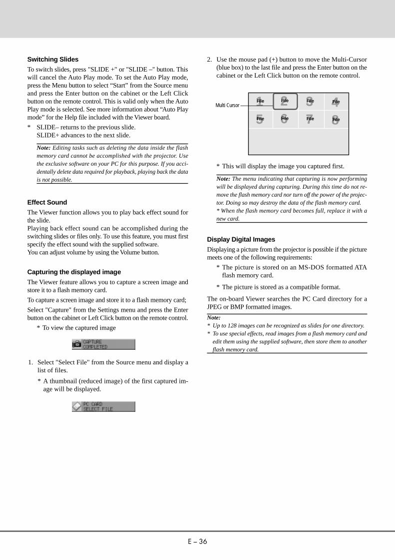
2. Use the mouse pad (+) button to move the Multi-Cursor(blue box) to the last file and press the Enter button on thecabinet or the Left Click button on the remote control.
* This will display the image you captured first.
Note: The menu indicating that capturing is now performingwill be displayed during capturing. During this time do not re-move the flash memory card nor turn off the power of the projec-tor. Doing so may destroy the data of the flash memory card.* When the flash memory card becomes full, replace it with anew card.
Display Digital Images
Displaying a picture from the projector is possible if the picturemeets one of the following requirements:
* The picture is stored on an MS-DOS formatted ATAflash memory card.
* The picture is stored as a compatible format.
The on-board Viewer searches the PC Card directory for aJPEG or BMP formatted images.
Note:* Up to 128 images can be recognized as slides for one directory.* To use special effects, read images from a flash memory card and
edit them using the supplied software, then store them to anotherflash memory card.
E – 37
This section describes the simple maintenance procedures youshould follow to replace the lamp and replace the batteries in theremote control.
Replacing The LampAfter your lamp has been operating for 1000 hours or longer, the“status” light in the cabinet will turn red. Even though the lamp maystill be working, replace it at 1000 hours to maintain optimalprojector performance.
CAUTION• DO NOT TOUCH THE LAMP immediately after it has been
used. It will be extremely hot. Allow at least one hour for thelamp to cool before handling.
• DO NOT REMOVE ANY SCREWS except the lamp coverset screw and two lamp case screws. You could receive anelectric shock.
• Turn off the main power to the projector and disconnect thepower cord. Allow at least one hour for the lamp to cool.
• The projector will turn off and go into stand by mode after1100 hours of service. If this happens, be sure to replace thelamp. If you continue to use the lamp after 1000 hours of use,the lamp bulb may shatter, and pieces of glass may bescattered in the lamp case. Do not touch them as the pieces ofglass may cause injury. If this happens, contact your NECdealer for lamp replacement.
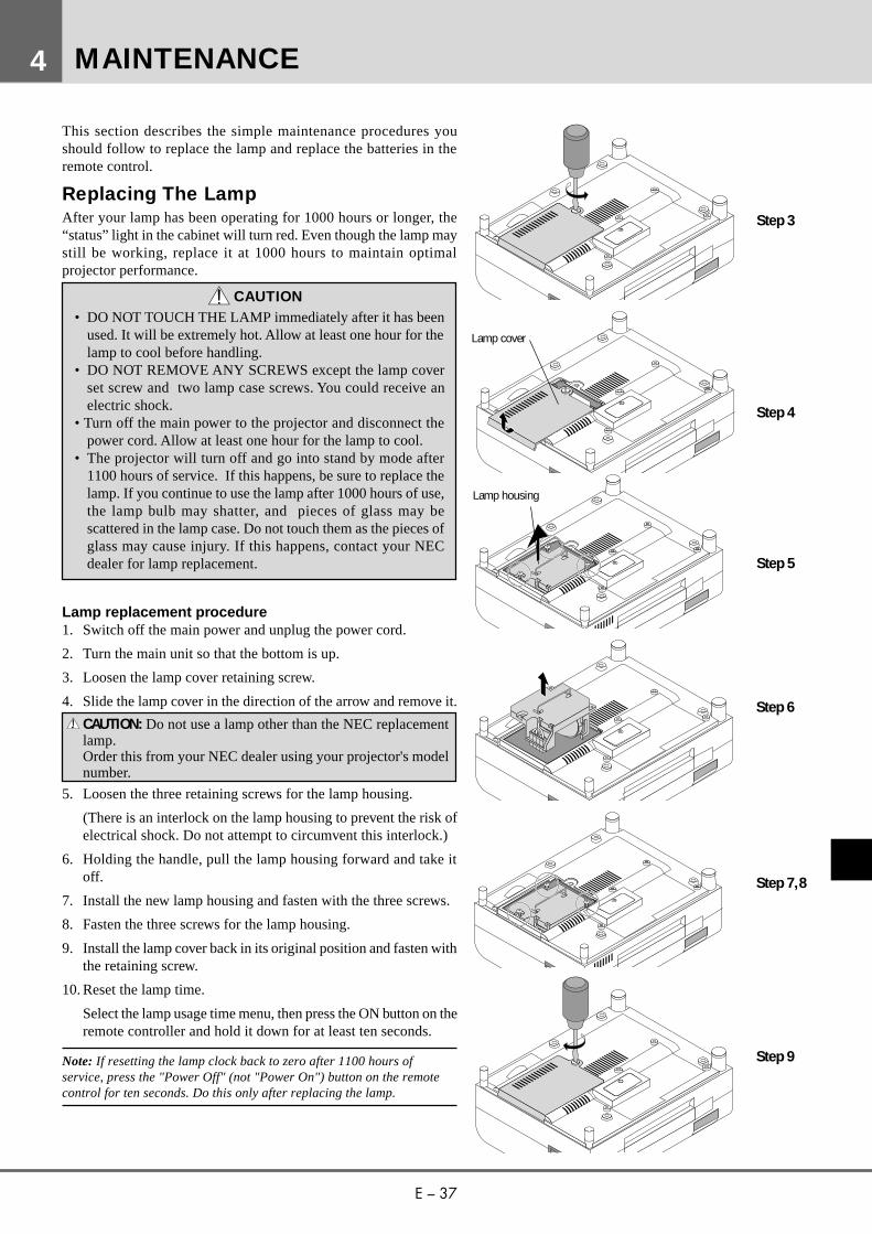
Lamp replacement procedure1. Switch off the main power and unplug the power cord.
2. Turn the main unit so that the bottom is up.
3. Loosen the lamp cover retaining screw.
4. Slide the lamp cover in the direction of the arrow and remove it.
CAUTION: Do not use a lamp other than the NEC replacementlamp.Order this from your NEC dealer using your projector's modelnumber.
5. Loosen the three retaining screws for the lamp housing.
(There is an interlock on the lamp housing to prevent the risk ofelectrical shock. Do not attempt to circumvent this interlock.)
6. Holding the handle, pull the lamp housing forward and take itoff.
7. Install the new lamp housing and fasten with the three screws.
8. Fasten the three screws for the lamp housing.
9. Install the lamp cover back in its original position and fasten withthe retaining screw.
10. Reset the lamp time.
Select the lamp usage time menu, then press the ON button on theremote controller and hold it down for at least ten seconds.
Note: If resetting the lamp clock back to zero after 1100 hours ofservice, press the "Power Off" (not "Power On") button on the remotecontrol for ten seconds. Do this only after replacing the lamp.
MAINTENANCE4
Step 3
Step 4
Step 5
Lamp cover
Step 6
Step 7,8
Step 9
Lamp housing

E – 38
Remote Control Battery Installation1. Press firmly and slide the battery cover off.2. Remove both old batteries and install new ones (AA). Ensure that you have the batteries' polarity
(+/–) aligned correctly.3. Slip the cover back over the batteries until it snaps into place.
Operating RangeRange of 360˚ and a distance of 7 m from the remote sensor.
30˚
30˚
Operation distance of 7m

E – 39
This section helps you resolve problems you may encounter while setting up or using your MultiSync LT100 Projector.
Status Light Messages
TROUBLESHOOTING
Status
m Normal
m The projector lamp has exceeded 1000 hours of operation and should be replaced.
m The lamp housing is not correctly installed. Install it correctly.
• The temperature protector has been triggered. If the room temperature is high, movethe projector to a cooler location. If the temperature inside the projector is high, checkthe cooling fan ventilation hole and the ventilation hole on the bottom of the projector.If any of the holes are blocked, remove whatever is blocking them.
• The temperature protector has been triggered. If you switch the main Power switchOff, then immediately switch it On again, sometimes the power does not come on. Ifthis happens, wait one minute, then switch the power On again.
m The cooling fan has stopped. Contact your NEC dealer for service.
m The lamp is not turned on.• The projector was turned off and back on too quickly. Turn off the projector,
wait one minute, then turn the projector back on. Or the lamp is burnt out.
Condition
OFF
On Continually
Blinking very rapidly(On and off in a cycle of 1 sec.)
Blinking rapidly(On and off in a cycle of 4 sec.)
Blinking Slowly(On and off in a cycle of 8 sec.)
Blinking very slowly(On and off in a cycle of 12 sec.)
5
E – 40
Common Problems & Solutions
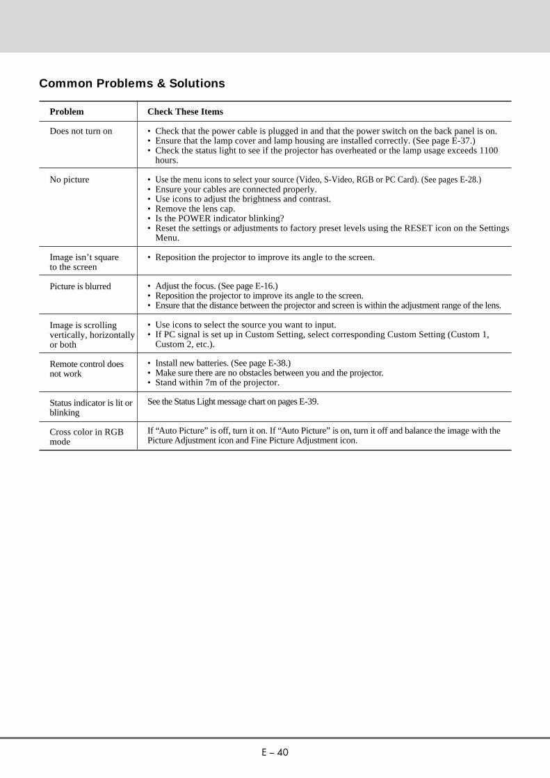
Problem
Does not turn on
No picture
Image isn’t squareto the screen
Picture is blurred
Image is scrollingvertically, horizontallyor both
Remote control doesnot work
Status indicator is lit orblinking
Cross color in RGBmode
Check These Items
• Check that the power cable is plugged in and that the power switch on the back panel is on.• Ensure that the lamp cover and lamp housing are installed correctly. (See page E-37.)• Check the status light to see if the projector has overheated or the lamp usage exceeds 1100
hours.
• Use the menu icons to select your source (Video, S-Video, RGB or PC Card). (See pages E-28.)• Ensure your cables are connected properly.• Use icons to adjust the brightness and contrast.• Remove the lens cap.• Is the POWER indicator blinking?• Reset the settings or adjustments to factory preset levels using the RESET icon on the Settings
Menu.
• Reposition the projector to improve its angle to the screen.
• Adjust the focus. (See page E-16.)• Reposition the projector to improve its angle to the screen.• Ensure that the distance between the projector and screen is within the adjustment range of the lens.
• Use icons to select the source you want to input.• If PC signal is set up in Custom Setting, select corresponding Custom Setting (Custom 1,
Custom 2, etc.).
• Install new batteries. (See page E-38.)• Make sure there are no obstacles between you and the projector.• Stand within 7m of the projector.
See the Status Light message chart on pages E-39.
If “Auto Picture” is off, turn it on. If “Auto Picture” is on, turn it off and balance the image with thePicture Adjustment icon and Fine Picture Adjustment icon.
E – 41
This section provides technical information about the MultiSync LT100 Projector's performance.
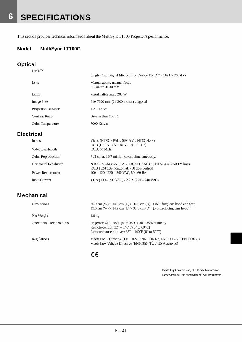
Model MultiSync LT100G
OpticalDMDTM
Single Chip Digital Micromirror Device(DMDTM), 10242768 dots
Lens Manual zoom, manual focusF 2.44 f =26-30 mm
Lamp Metal halide lamp 280 W
Image Size 610-7620 mm (24-300 inches) diagonal
Projection Distance 1.2 – 12.3m
Contrast Ratio Greater than 200 : 1
Color Temperature 7000 Kelvin
ElectricalInputs Video (NTSC / PAL / SECAM / NTSC 4.43)
RGB (H : 15 – 85 kHz, V : 50 – 85 Hz)Video Bandwidth RGB: 60 MHz
Color Reproduction Full color, 16.7 million colors simultaneously.
Horizontal Resolution NTSC / YCbCr 550, PAL 350, SECAM 350, NTSC4.43 350 TV linesRGB 1024 dots horizontal, 768 dots vertical
Power Requirement 100 – 120 / 220 – 240 VAC, 50 / 60 Hz
Input Current 4.6 A (100 – 200 VAC) / 2.2 A (220 – 240 VAC)
Mechanical
Dimensions 25.0 cm (W)214.2 cm (H)234.0 cm (D) (Including lens hood and feet)25.0 cm (W)214.2 cm (H)232.0 cm (D) (Not including lens hood)
Net Weight 4.9 kg
Operational Temperatures Projector: 41° – 95°F (5° to 35°C), 30 – 85% humidityRemote control: 32° – 140°F (0° to 60°C)Remote mouse receiver: 32° – 140°F (0° to 60°C)
Regulations Meets EMC Directive (EN55022, EN61000-3-2, EN61000-3-3, EN50082-1)Meets Low Voltage Directive (EN60950, TÜV GS Approved)
SPECIFICATIONS
Digital Light Proccessing, DLP, Digital MicromirrorDevice and DMD are trademarks of Texas Instruments.
6
E – 42
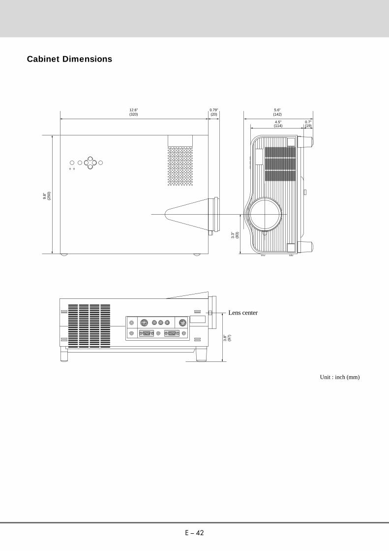
Cabinet Dimensions
Unit : inch (mm)
12.6"(320)
9.8"
(250
)
3.8"
(97)
0.79"(20)
5.6"(142)
4.5"(114)
0.7"(19)
3.3"
(83)
Lens center
E – 43
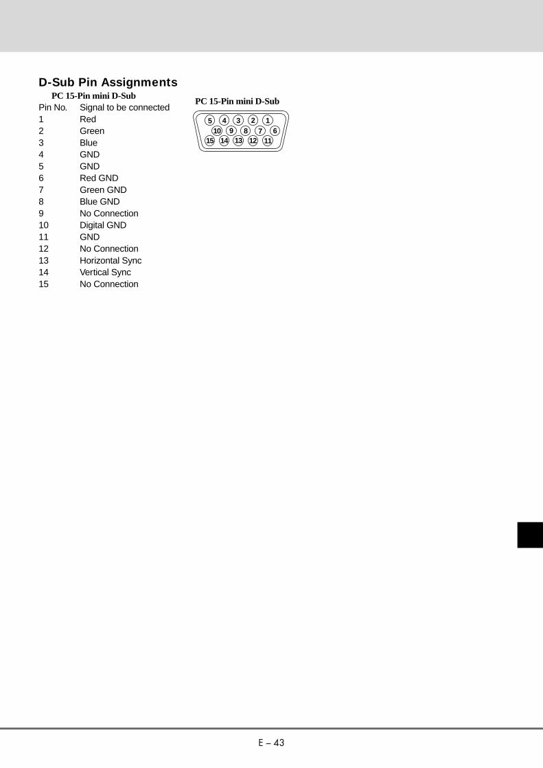
D-Sub Pin Assignments PC 15-Pin mini D-SubPin No. Signal to be connected1 Red2 Green3 Blue4 GND5 GND6 Red GND7 Green GND8 Blue GND9 No Connection10 Digital GND11 GND12 No Connection13 Horizontal Sync14 Vertical Sync15 No Connection
12345
1112131415678910
PC 15-Pin mini D-Sub

E – 44
Timing Chart
Y/N Signal Resolution Refresh F.H. DotRate (Hz) (kHz) Clk(MHz)
Y NTSC 6402480 60 15.734 -Y PAL 7682576 50 15.625 -Y SECAM 7682576 50 15.625 -Y VESA 6402350 85.08 37.86 31.5Y IBM 6402400 70 31.47 25.175Y VESA 6402400 85.08 37.86 31.5Y MAC 6402400 66 35 30.24Y VESA 6402480 59.94 31.47 25.175Y IBM 6402480 60 31.47 25.175Y MAC 6402480 60 31.47 25.175Y MAC 6402480 66.7 34.97 31.334Y MAC 6402480 66.67 35 30.24Y VESA 6402480 72.81 37.86 31.5Y VESA 6402480 75 37.5 31.5Y IBM 6402480 75 39.375 31.49Y VESA 6402480 85.01 43.269 36Y IBM 7202350 70.09 31.469 28.322Y IBM 7202400 70.09 31.4469 28.322Y VESA 7202400 85.04 37.927 40Y IBM 7202350 87.85 39.44 35.5Y IBM 7202400 87.7 39.375 35.5Y VESA 8002600 56.25 35.16 36Y VESA 8002600 60.32 37.879 40Y VESA 8002600 72.19 48.077 50Y VESA 8002600 75 46.88 49.5Y VESA 8002600 85.06 53.674 56.25Y MAC 8322624 74.55 49.725 57.283N VESA 10242768 43interlace 35.5 44.9Y VESA 10242768 60 48.363 65Y VESA 10242768 70.07 57.476 75Y IBM 10242768 72.03 58.131 79Y MAC 10242768 74.93 60.241 80Y VESA 10242768 75.03 60.023 78.75Y VESA 10242768 85 68.677 94.5Y SGI 10242768 60.4 49.7 70# MAC 11522870 75.6 68.7 100# SUN 11522900 65.95 61.769 92.94# SGI 11522900 70.05 71.736 105.6# SGI 128021024 60 63.9 107.35# VESA 128021024 60.02 64.286 108# MAC 128021024 69.89 74.882 118.5# HP 128021024 72.01 78.125 135# VESA 128021024 75.03 79.976 135# SUN 128021024 76.11 81.13 135
# 11522870, # 11522900 and #128021024 images are compressed into10242768
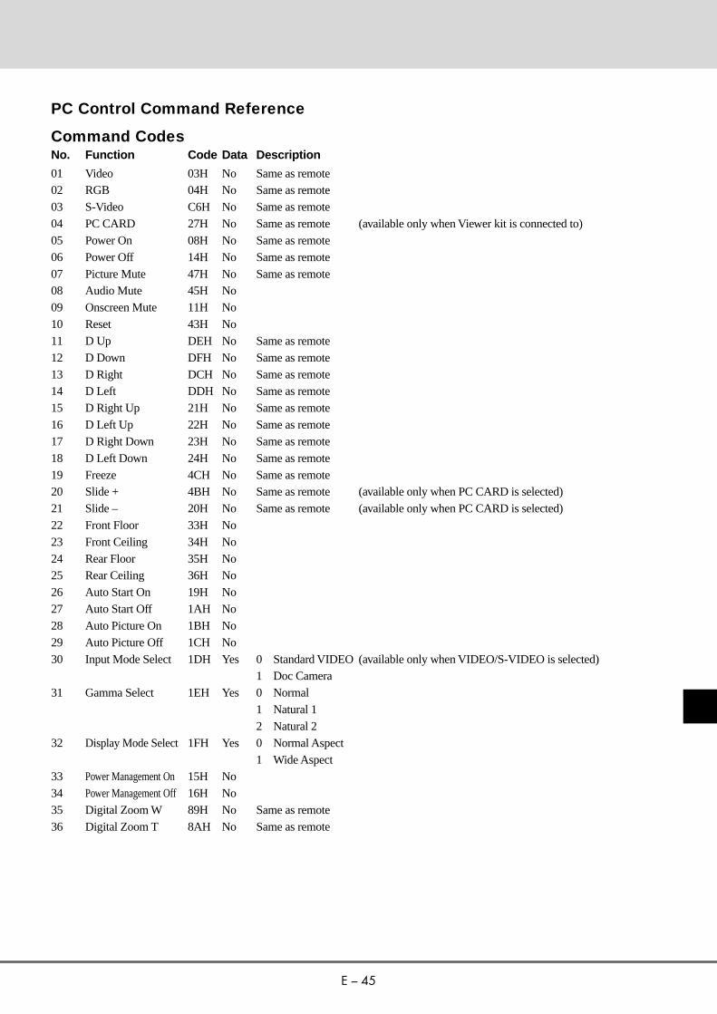
E – 45
01 Video 03H No Same as remote02 RGB 04H No Same as remote03 S-Video C6H No Same as remote04 PC CARD 27H No Same as remote (available only when Viewer kit is connected to)05 Power On 08H No Same as remote06 Power Off 14H No Same as remote07 Picture Mute 47H No Same as remote08 Audio Mute 45H No09 Onscreen Mute 11H No10 Reset 43H No11 D Up DEH No Same as remote12 D Down DFH No Same as remote13 D Right DCH No Same as remote14 D Left DDH No Same as remote15 D Right Up 21H No Same as remote16 D Left Up 22H No Same as remote17 D Right Down 23H No Same as remote18 D Left Down 24H No Same as remote19 Freeze 4CH No Same as remote20 Slide + 4BH No Same as remote (available only when PC CARD is selected)21 Slide – 20H No Same as remote (available only when PC CARD is selected)22 Front Floor 33H No23 Front Ceiling 34H No24 Rear Floor 35H No25 Rear Ceiling 36H No26 Auto Start On 19H No27 Auto Start Off 1AH No28 Auto Picture On 1BH No29 Auto Picture Off 1CH No30 Input Mode Select 1DH Yes 0 Standard VIDEO (available only when VIDEO/S-VIDEO is selected)
1 Doc Camera31 Gamma Select 1EH Yes 0 Normal
1 Natural 12 Natural 2
32 Display Mode Select1FH Yes 0 Normal Aspect1 Wide Aspect
33 Power Management On 15H No34 Power Management Off 16H No35 Digital Zoom W 89H No Same as remote36 Digital Zoom T 8AH No Same as remote
PC Control Command Reference
Command CodesNo. Function Code Data Description

E – 46
Command Codes (continued)No. Function Code Data Description
37 Brightness 60H Yes 0 (00H) –– 63 (3FH)38 Contrast 62H Yes 0 (00H) –– 63 (3FH)39 Color 64H Yes 0 (00H) –– 63 (3FH)40 Tint 66H Yes -32 (E0H) –– 31 (1FH)41 Sharpness 68H Yes 0 (00H) –– 63 (3FH)42 Audio Volume 6AH Yes 0 (00H) –– 63 (3FH)43 Picture Adj 70H Yes -32 (FFE0H)–– 31 (001FH)44 Fine Picture 6EH Yes 0 (00H) –– 127 (7FH)45 H Position 72H Yes -128 (80H) –– 127 (7FH)46 V Position 74H Yes -64 (C0H) –– 63 (3FH)47 Lamp Reset 3FH No48 Lamguage Select 3DH Yes 0 English
1 German2 French3 Italian4 Spanish5 Swedish6 Japanese
WHITE BALANCE49 Sub Brightness R 75H Yes 0 (00H) –– 63 (3FH)50 Sub Brightness G 76H Yes 0 (00H) –– 63 (3FH)51 Sub Brightness B 77H Yes 0 (00H) –– 63 (3FH)52 Sub Contrast R 78H Yes 0 (00H) –– 63 (3FH)53 Sub Contrast G 79H Yes 0 (00H) –– 63 (3FH)54 Sub Contrast B 7AH Yes 0 (00H) –– 63 (3FH)
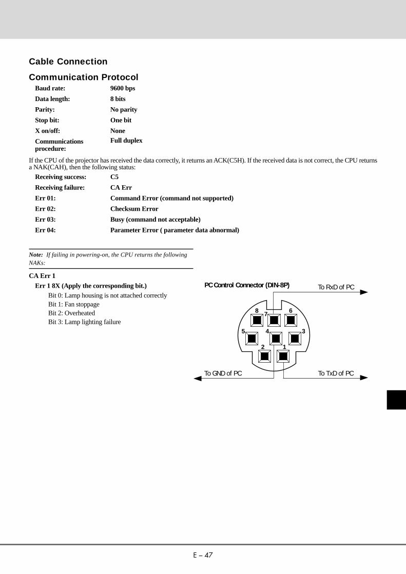
E – 47
Cable Connection
Communication ProtocolBaud rate: 9600 bps
Data length: 8 bits
Parity: No parity
Stop bit: One bit
X on/off: None
Communications Full duplexprocedure:
If the CPU of the projector has received the data correctly, it returns an ACK(C5H). If the received data is not correct, the CPU returnsa NAK(CAH), then the following status:
Receiving success: C5
Receiving failure: CA Err
Err 01: Command Error (command not supported)
Err 02: Checksum Error
Err 03: Busy (command not acceptable)
Err 04: Parameter Error ( parameter data abnormal)
Note: If failing in powering-on, the CPU returns the followingNAKs:
CA Err 1
Err 1 8X (Apply the corresponding bit.)Bit 0: Lamp housing is not attached correctlyBit 1: Fan stoppageBit 2: OverheatedBit 3: Lamp lighting failure
12
5 4 3
678
To RxD of PC©
PC Control Connector (DIN-8P)
To TxD of PC§
To GND of PC©


![Getting Started in RobotC // Comment task main() motor[] {} wait1Msec() ; = Header Code Compile Download Run Take out your notes](https://img.pdfslide.us/doc/110x75/5697bfc91a28abf838ca8ca7/getting-started-in-robotc-comment-task-main-motor-wait1msec-.jpg)