Embed Size (px)
Citation preview

CES TRANSACTIONS ON ELECTRICAL MACHINES AND SYSTEMS, VOL. 2, NO. 4, DECEMBER 2018 425
Abstract—The multiscale finite element method (MsFEM)
combined with conventional finite element method (CFEM) is
proposed to solve static magnetic field in the ribbon magnetic core
with non-periodical corners considered. Firstly, a simple
2-dimensional electrostatic problem is used to introduce the
MsFEM implementation process. The results are compared to
analytical method, as well as conventional FEM. Then, an exam-
ple of magneto-static problem is considered for a ribbon magnetic
core built sheet by sheet as well as corners taken into considera-
tion. Conventional FEM and MsFEM are used to compute the
magneto-static field by adopting scalar magnetic potential. Both
magnetic potential and magnetic flux density on a certain path are
compared. It is shown that the results obtained by MsFEM agree
well with the one from conventional FEM. Moreover, MsFEM
combined with FEM is potentially a general strategy for mul-
tiscale modeling of ribbon magnetic cores with complex and
non-periodical structures considered, like corners and T-joints,
which can effectively reduce the computational cost.
Index Terms—Magneto-static, multiscale finite element, mul-
tiscale modeling, ribbon magnetic core.
I. INTRODUCTION
HE discretization of ribbon magnetic cores and laminated
iron cores, i.e. by FEM, would lead to a prohibitively large
system of equations since ribbon magnetic core and laminated
iron core can be viewed as highly heterogeneous models. In
three-dimensional (3-D) case, the issue of computational cost
becomes even more severe. It is a huge difficulty for the mod-
ern computer to solve. Surely, it is far away from being a rou-
tine task for engineers in the design and performance analysis
of electrical devices with such structure. To overcome this
unpleasant fact, homogenization methods (HM) have been
applied. In 2003, Dular et al adopted FEM combined with HM
to study a three-dimensional 3-D magnetic field computation
where the eddy currents in laminated stacks were taken into
account [1]. In [2], [3], Gyselinck et al presented a novel
time-domain HM for laminated iron cores in 3-D FE models for
Manuscript was submitted for review on 29, April, 2018.
Hailin Li is currently studying for a Ph.D. in Xi’an Jiaotong University
(e-mail: [email protected]). Zuqi Tang is the Associate Professor in Electrical Engineering Department
in University of Lille (e-mail: [email protected]).
Shuhong Wang is currently a Professor with the School of Electrical Engineering, Xi’an Jiaotong University. (e-mail: [email protected])
Jianguo Zhu is the Professor in University of Sydney (e-mail:
[email protected]). Digital Object Identifier 10.30941/CESTEMS.2018.00054
linear and nonlinear problems, respectively. In [4], Niyonzima
et al adopted heterogeneous multiscale method to study lami-
nated cores, which still needed homogenized material proper-
ties on representative volume elements (RVEs). Average
quantities can be obtained by these computational HM methods.
More often, it is desirable to capture the fine-scale effects, like
the eddy current and magnetic distribution in each sheet of the
ribbon magnetic core and iron core for loss calculation. In order
to achieve this objective, researchers proposed some solutions.
Duan et al proposed an improved extended finite element
method (XFEM) for modeling electromagnetic devices with
multiple nearby geometrical interfaces and discontinuities in
electric fields [5]. Meanwhile, a ‘multiscale finite element
method’ for the 2-D and 3-dimensional eddy current problem in
iron laminates was put forwarded in [6], [7]. The mesh used for
these two approaches are independent of geometries, and
‘correction functions’ (CFs) or ‘special functions’(SFs) are
needed for basis functions construction of coarse elements first.
For complex structures, like corners and T-joints of the trans-
formers, it is difficult to find these CFs or SFs. It needs to find
these CFs or SFs for each coarse element when non-periodical
structures are of interest.
In this paper, we aimed to capture the magnetic distribution
in small-scale of ribbon magnetic cores using another MsFEM
which is firstly proposed by Hou and Wu for the elliptic prob-
lems in composite materials and porous media [8]. It has been
used for fluid flow [9], groundwater flow [10], and mechanical
analysis of heterogeneous materials [11]. This MsFEM was
first introduced by Bottauscio and Manzin to solve eddy current
problem, but with granular magnetic materials [12]. Compared
with other multiscale modeling methods, MsFEM proposed by
Hou and Wu do not use explicit expressions for basis functions
construction. The basis functions are a set of numerical values
on fine grids of each coarse element, which means that it can
cope with basis functions construction of arbitrary geometries
easily, such as T-joints and corners of an iron core. Hence, it is
a general way to construct basis functions for elements with
complex structures. In addition, results on small scale resolved
by MsFEM can be as good as those solved by the CFEM. In this
work, we developed this approach to model a magneto-static
problem with application to magnetic core of a high-frequency
transformer, and the magnetic distribution and flux density in
each ribbon will be investigated. The organization of the paper
is as follows: Firstly, a brief introduction to MsFEM and a
simple case using the analytical method, FEM, and MsFEM are
Multiscale Modeling of Magnetic Distribution of
Ribbon Magnetic Cores
Hailin Li, Zuqi Tang, Shuhong Wang, and Jianguo Zhu
T
426 CES TRANSACTIONS ON ELECTRICAL MACHINES AND SYSTEMS, VOL. 2, NO. 4, DECEMBER 2018
examined. Then, application to magneto-static problem of
MsFEM combined with FEM is considered in section III. The
conclusion is given in section IV.
II. MATHEMATICAL MODEL
A. A brief introduction to MsFEM
The main idea of MsFEM is to construct multiscale basis
functions, which capture fine-scale information within each
coarse grid. The fine-scale information is then brought to
coarse-scale through the coupling of global stiffness matrix.
Thus, effects of fine-scale on the coarse-scale can be captured.
Similar to XFEM, for our MsFEM, the mesh is independent of
geometries, and a coarse grid may include several materials.
In general, there are three major steps for the implementation
of MsFEM: multiscale basis function construction, global
formulation, and downscaling analysis. To demonstrate the
performance and implementation process of the MsFEM, a
simple 2-D electrostatic problem is considered. The results
obtained by MsFEM are compared with the analytical method,
as well as the conventional FEM.
The governing equation and boundary conditions for the
electrostatic problem are as follows:
=0 =0.9
0,
0, 1.x x
u u
x x y y
u u
(1)
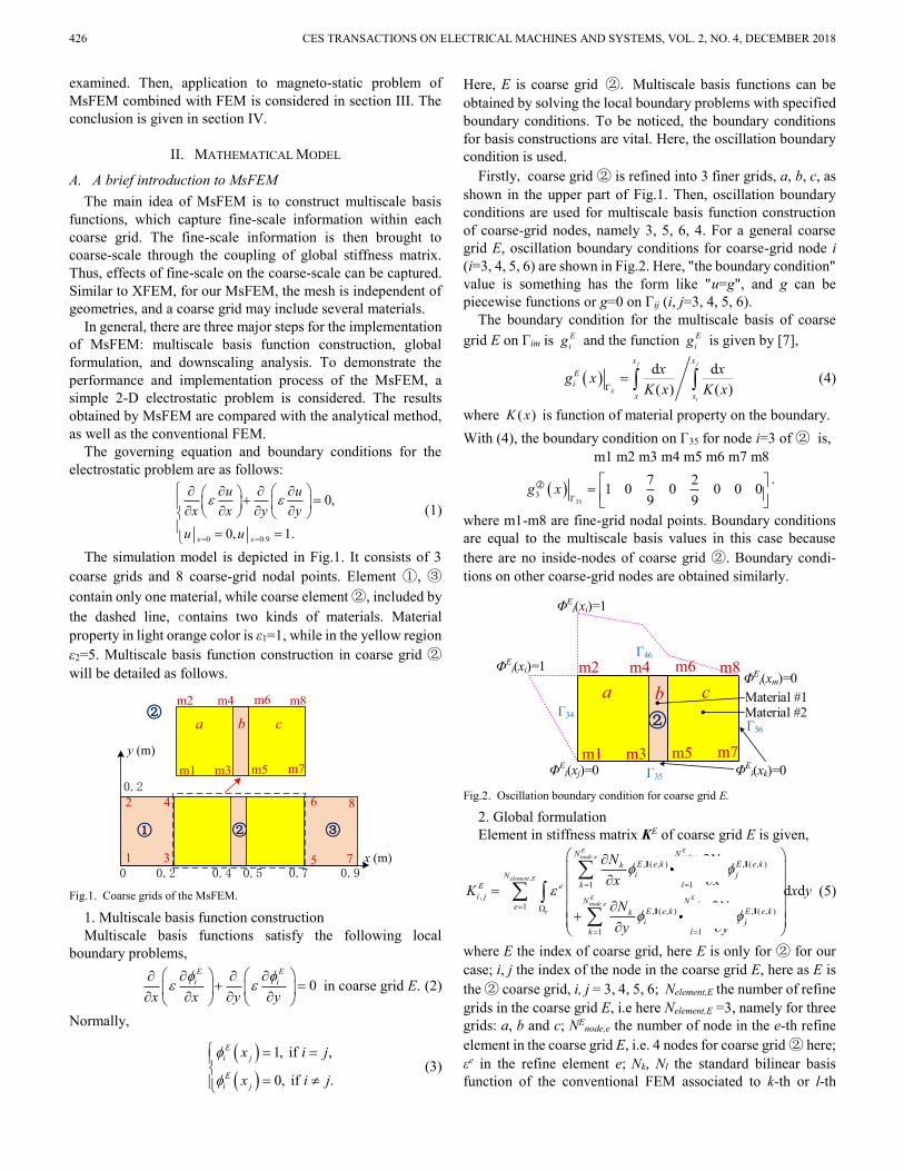
The simulation model is depicted in Fig.1. It consists of 3
coarse grids and 8 coarse-grid nodal points. Element ①, ③
contain only one material, while coarse element ②, included by
the dashed line, contains two kinds of materials. Material
property in light orange color is ε1=1, while in the yellow region
ε2=5. Multiscale basis function construction in coarse grid ②
will be detailed as follows.
②m2
m1
m4
m3
m6
m5
m8
m7
a b c
② ③
1 3 5 7
2 4 6 8
0 0.2 0.4 0.5 0.7 0.9
0.2
x (m)
y (m)
①
Fig.1. Coarse grids of the MsFEM.
1. Multiscale basis function construction
Multiscale basis functions satisfy the following local
boundary problems,
0E E
i i
x x y y
in coarse grid E. (2)
Normally,
1, if ,
0, if .
E
i j
E
i j
x i j
x i j
(3)
Here, E is coarse grid ②. Multiscale basis functions can be
obtained by solving the local boundary problems with specified
boundary conditions. To be noticed, the boundary conditions
for basis constructions are vital. Here, the oscillation boundary
condition is used.
Firstly, coarse grid ② is refined into 3 finer grids, a, b, c, as
shown in the upper part of Fig.1. Then, oscillation boundary
conditions are used for multiscale basis function construction
of coarse-grid nodes, namely 3, 5, 6, 4. For a general coarse
grid E, oscillation boundary conditions for coarse-grid node i
(i=3, 4, 5, 6) are shown in Fig.2. Here, "the boundary condition"
value is something has the form like "u=g", and g can be
piecewise functions or g=0 on Γij (i, j=3, 4, 5, 6).
The boundary condition for the multiscale basis of coarse
grid E on Γim is E
ig and the function E
ig is given by [7],
d d
( ) ( )
j j
ij
i
x x
E
i
x x
x xg x
K x K x (4)
where ( )K x is function of material property on the boundary.
With (4), the boundary condition on Γ35 for node i=3 of ② is,
35
3
m1 m2 m3 m4 m5 m6 m7 m8
7 21 0 0 0 0 0
9 9g x
② .
where m1-m8 are fine-grid nodal points. Boundary conditions
are equal to the multiscale basis values in this case because
there are no inside-nodes of coarse grid ②. Boundary condi-
tions on other coarse-grid nodes are obtained similarly.
②
m2
m1
m4
m3
m6
m5
m8
m7
a b c Material #1
ΦEi(xi)=1
ΦEi(xi)=1
ΦEi(xk)=0
Material #2
ΦEi(xm)=0
ΦEi(xj)=0
Γ46
Γ34 Γ56
Γ35 Fig.2. Oscillation boundary condition for coarse grid E.
2. Global formulation
Element in stiffness matrix KE of coarse grid E is given,
, ,
,
, ,
, ( , ) , ( , )
1 1
,
1, ( , ) , ( , )
1 1
d d
E Enode e node e
element E
E Enode e node e
e
N N
E e k E e kk li jN
k lE e
i jN N
eE e k E e kk l
i j
k l
N N
x xK x y
N N
y y
I I
I I
(5)
where E the index of coarse grid, here E is only for ② for our
case; i, j the index of the node in the coarse grid E, here as E is
the ② coarse grid, i, j = 3, 4, 5, 6; Nelement,E the number of refine
grids in the coarse grid E, i.e here Nelement,E =3, namely for three
grids: a, b and c; NEnode,e the number of node in the e-th refine
element in the coarse grid E, i.e. 4 nodes for coarse grid ② here;
εe in the refine element e; Nk, Nl the standard bilinear basis
function of the conventional FEM associated to k-th or l-th
LI et al. : MULTISCALE MODELING OF MAGNETIC DISTRIBUTION OF RIBBON MAGNETIC CORES 427
node in the refined mesh; I(e, k) represents the index of k-th
node of the e-th refined mesh in the coarse grid E. For example,
when e=1, we consider the a refined grid, the four nodes are m1,
m3, m4 and m2.
With (5), the stiffness matrix of coarse grid ② is,
3 4 5 6
3 4.5617 4.0062 0.6883 1.2438
4 4.0062 4.5617 1.2438 0.6883
5 0.6883 1.2438 4.5617 4.0062
6 1.2438 0.6883 4.0062 4.5617
②K
where the number 3-6, on the top and the left side is the index of
coarse-grid node.
Meanwhile, the stiffness matrices of coarse grid ①, ③ can
be obtained by the conventional FEM.
3. Downscaling analysis
The solution on fine grids can be obtained by a linear com-
bination of the multiscale basis function, as shown below.
E E E E
i i j j k k m mu u u u u (6)
Results calculated by analytical method, FEM and MsFEM
are summarized in Table I. From this table, it is obvious that the
result solved by MsFEM agrees well with analytical method
and FEM. Validation of MsFEM can be proved. TABLE I
RESULT COMPARISON OF ANALYTICAL METHOD, FEM, MSFEM
Coordinate Analytical FEM MsFEM
(0.2,0) 0.3448 0.3448 0.3448
(0.2,0.2) 0.3448 0.3448 0.3448
(0.4,0) 0.4138 0.4138 0.4138
(0.4,0.2) 0.4138 0.4138 0.4138
(0.5,0) 0.5862 0.5862 0.5862
(0.5,0.2) 0.5862 0.5862 0.5862
(0.7,0) 0.6552 0.6552 0.6552
(0.7,0.2) 0.6552 0.6552 0.6552
Pseudo-code
A simple pseudo-code below outlines the implementation of
MsFEM. It is obvious that this method can be realized very
easily within the existing finite element code.
Algorithm:
Set up the coarse grid configuration, and obtain the fine grids
information of each coarse grid
For each coarse grid E, do
-For each vertex i
-Get E
i and boundary conditions
-End for
End do
Assemble macro stiffness matrix of coarse grid
Assemble macro load vector
Solve the global formulation
Down scaling analysis.
III. APPLICATION IN MAGNETO-STATIC PROBLEMS
A. Mathematical model
A magneto-static problem in 2-D is considered, and the
governing equation of magneto-magnetic field is given by,
z zs
0 0
1 1
r r
A Aj
x x y y
. (7)
Boundary conditions are
1 20, on S SzA , , (8)
and natural Neumann conditions on S3, S4.
x
y
A Bx
y
Js
s1
s2 s3
s4
C D
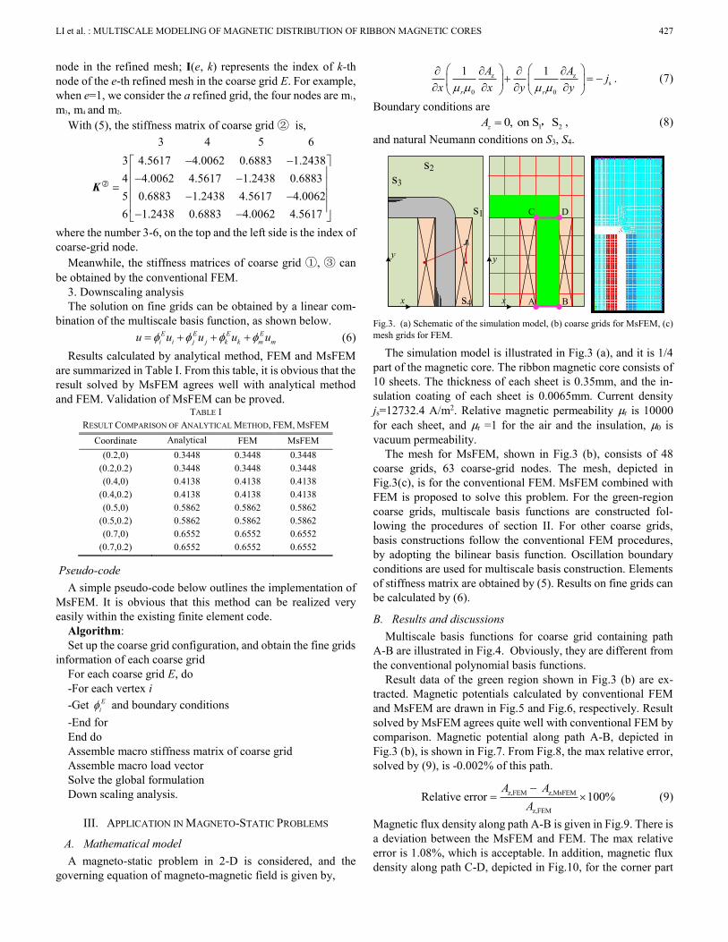
Fig.3. (a) Schematic of the simulation model, (b) coarse grids for MsFEM, (c)
mesh grids for FEM.
The simulation model is illustrated in Fig.3 (a), and it is 1/4
part of the magnetic core. The ribbon magnetic core consists of
10 sheets. The thickness of each sheet is 0.35mm, and the in-
sulation coating of each sheet is 0.0065mm. Current density
js=12732.4 A/m2. Relative magnetic permeability μr is 10000
for each sheet, and μr =1 for the air and the insulation, μ0 is
vacuum permeability.
The mesh for MsFEM, shown in Fig.3 (b), consists of 48
coarse grids, 63 coarse-grid nodes. The mesh, depicted in
Fig.3(c), is for the conventional FEM. MsFEM combined with
FEM is proposed to solve this problem. For the green-region
coarse grids, multiscale basis functions are constructed fol-
lowing the procedures of section II. For other coarse grids,
basis constructions follow the conventional FEM procedures,
by adopting the bilinear basis function. Oscillation boundary
conditions are used for multiscale basis construction. Elements
of stiffness matrix are obtained by (5). Results on fine grids can
be calculated by (6).
B. Results and discussions
Multiscale basis functions for coarse grid containing path
A-B are illustrated in Fig.4. Obviously, they are different from
the conventional polynomial basis functions.
Result data of the green region shown in Fig.3 (b) are ex-
tracted. Magnetic potentials calculated by conventional FEM
and MsFEM are drawn in Fig.5 and Fig.6, respectively. Result
solved by MsFEM agrees quite well with conventional FEM by
comparison. Magnetic potential along path A-B, depicted in
Fig.3 (b), is shown in Fig.7. From Fig.8, the max relative error,
solved by (9), is -0.002% of this path.
z,FEM z,MsFEM
z,FEM
Relative error 100%
A A
A
(9)
Magnetic flux density along path A-B is given in Fig.9. There is
a deviation between the MsFEM and FEM. The max relative
error is 1.08%, which is acceptable. In addition, magnetic flux
density along path C-D, depicted in Fig.10, for the corner part

428 CES TRANSACTIONS ON ELECTRICAL MACHINES AND SYSTEMS, VOL. 2, NO. 4, DECEMBER 2018
of the core are examined to demonstrate accuracy for its po-
tential in arbitrary geometry modeling and calculation such as
T-joints and corners. The maximum relative error is 4.75%.
0.010 0.011 0.012 0.0130.000
0.005
0.010
0.015
y(m
)
x(m)
0
0.1250
0.2500
0.3750
0.5000
0.6250
0.7500
0.8750
1.000
(a) (b)
(c) (d)
Fig.4. Multiscale basis for coarse grid containing path A-B.
Fig.5. Magnetic potential distribution calculated by FEM.
Fig.6. Magnetic potential distribution calculated by MsFEM.
Computation burden comparison of MsFEM and FEM are
shown in Table II. It is found that equation systems obtained by
using MsFEM is much smaller. The solving scale of MsFEM is
1/55.7 times as large of FEM. What is more, the normalized
multiplication times for stiffness matrix formulation is 0.6284
by adopting the MsFEM combined with FEM. Obviously,
MsFEM combined with FEM could significantly reduce the
computation burden while the accuracy is maintained.
Fig.7. Magnetic potential on path A-B solved by FEM and MsFEM.
Fig.8. Relative error along path A-B.
Fig.9. Magnetic flux density on path A-B computed by FEM and MsFEM.
Fig.10. Magnetic flux density on path C-D computed by FEM and MsFEM.

LI et al. : MULTISCALE MODELING OF MAGNETIC DISTRIBUTION OF RIBBON MAGNETIC CORES 429
IV. CONCLUSION
MsFEM combined with conventional FEM is proposed to
solve magneto-static problem of ribbon magnetic core. Firstly,
validation of MsFEM is examined by a simple case. Then, a
magneto-static problem considered. By comparison the com-
putation cost, it can be concluded that MsFEM combined with
FEM can alleviate the computational burden and requirement
of hardware for ribbon magnetic core’s simulation effectively.
What is more, it is a general and flexible method since it be
implemented easily within the existing finite element code.
TABLE II
COMPUTATION BURDEN COMPARISON OF MSFEM AND FEM
FEM MsFEM
Element number 3396 48
Node number 3510 63
Multiplication times
(normalized) 1 0.6284
REFERENCES
[1] P. Dular, J. Gyselinck, C. Geuzaine, N. Sadowski, and J. Bastos, “A 3-D magnetic vector potential formulation taking eddy currents in lamination stacks into account,” IEEE Trans. Magn., vol. 39, pp. 1424–1427, Mar. 2003.
[2] J. Gyselinck, R. Sabariego, and P. Dular, “A nonlinear time-domain homogenization technique for laminated iron cores in three-dimensional finite-element models,” IEEE Trans. Magn., vol. 42, pp. 763–766, Apr., 2006.
[3] J. Gyselinck, P. Dular. “A time-domain homogenization technique for laminated iron cores in 3-D finite-element models,” IEEE Trans. Magn., vol. 40, pp. 856-859, Feb. 2004.
[4] I. Niyonzima, R. V. Sabariego,P. Dular,C. Geuzaine, “Computational homogenization for laminated ferromagnetic cores in magnetodynamics,” IEEE Trans. on Magn., vol. 49, no. 5, pp. 2049-2052, 2013.
[5] N. Duan, W. Xu, S. Wang, J. Zhu, and Y. Guo, “An improved XFEM with multiple high-order enrichment functions and low-order meshing ele-ments for field analysis of electromagnetic devices with multiple nearby geometrical interfaces,” IEEE Trans. on Magn., vol. 51, pp. 1-4, Mar. 2015.
[6] K. Hannukainen, J. Schöberl, “Two-scale homogenization of the nonlinear eddy current problem with FEM,” IEEE Trans. on Magn., vol.50, pp.413-416, Feb., 2014.
[7] K. Hollaus, J. Schöberl, “Multi-scale FEM and magnetic vector potential a for 3D eddy currents in laminated media,” Compel International Journal of Computations & Mathematics in Electrical vol. 34, pp.1598-1608, 2015.
[8] T. Y Hou, X. Wu, “A multiscale finite element method for elliptic problems in composite materials and porous media,” Journal of Computational Physics, vol. 134, pp.169-189, 1997.
[9] T. Y Hou, “Multiscale modelling and computation of fluid flow,” Inter-national Journal for Numerical Methods in Fluids, vol. 47, pp. 707-719, 2010.
[10] Q. Xue, S. Ye, “Application of multi-scale finite element method to simulation of groundwater flow,” Journal of hydraulic engineering, vol. 35, pp.07-13, 2004.
[11] H. Zhang, J. Lü, Z. Fu, “Extended multiscale finite element method for mechanical analysis of heterogeneous materials,” Acta Mechanica Sinica, vol. 26, pp. 899-920, 2010.
[12] O. Bottauscio, A. Manzin, “Comparison of multiscale models for eddy current computation in granular magnetic materials,” Journal of Com-putational Physics, vol. 253, pp.1-17, 2013.
Hailin Li was born in Hubei, China, in
1988. He received his B.E. from the Henan
Polytechnic University, Henan, China, in
2011; M.E. from Shenyang University of
Technology, Liaoning, China, in 2014.
He is currently studying for a Ph.D. in
Xi’an Jiaotong University, Shaanxi, China,
all in electrical engineering. His major
research interest is numerical analysis of
electromagnetic field and multi-physics coupling.
Zuqi Tang received the B.S. (2007) in
mathematics from Wuhan University,
China, the M.S. (2009) in applied mathe-
matics, and the Ph.D. (2012) in electrical
engineering in the University of Lille.
From 2017, he is the Associate Professor in
Electrical Engineering Department in
University of Lille.
His current research is focused on the
numerical modeling and analysis in computational electro-
magnetism, as well as coupled multi-physical problems.
Shuhong Wang (M’11-SM’13) was born
in Shaanxi, China, in 1968. He received the
B.E., M.E., and Ph.D. degrees from Xi’an
Jiaotong University, Xi’an, China, in 1990,
1993, and 2002, respectively, all in
electrical engineering.
He is currently a Professor with the School
of Electrical Engineering, Xi’an Jiaotong
University.His research interests include
numerical analysis of electromagnetic field, and design and
optimization of electromagnetic devices.
Jianguo Zhu (S’93–M’96–SM’03) Prof.
J.G. Zhu received his BE in 1982 from
Jiangsu Institute of Technology, ME in
1987 from Shanghai University of Tech-
nology, China, and PhD in 1995 from
University of Technology, Sydney (UTS),
Australia, all in electrical engineering.
From 1982 to 1990, he was employed by
Jiangsu Institute of Technology, China, as
an associate lecturer and later on lecturer. In 1994, he was
appointed a lecturer in School of Electrical Engineering at UTS.
He was promoted to full professor of electrical engineering in
2004. Professor Zhu joined the University of Sydney in 2018.
His current research interests include electromagnetics, mag-
netic properties of materials, electrical machines and drives,
power electronics, and green energy systems.