Embed Size (px)
Citation preview

PAP-5&9
HYDRAULICS BRANCH OFFICIAL FILE COPY
MULTIPORT SLEEVE VALVE DEVELOPMENT
AND APPLICATION
m
PHILLIP H. BURGI, EDWARD 0. GREEN, AND RAOUL E.
A,S,C,E,
JOURNAL OF THE HYDRAULICS DIVISION
JANUARY 1981

16986 JANUARY 1981 HY1
JOURNAL OF THE HYDRAULICS DIVISION
MULTIPORT SLEEVE VALVE DEVELOPMENT
AND APPLICATION
By Philip H. Burgi,' Edward O. Green,2 and Raoul E. Thibault'
WRODUCTION
The design and construction of long aqueducts to supply municipal and industrial water have presented the need to develop a control valve and energy dissipator that would be compatible with the aqueduct system. A valve design is needed that will: (1) Adequately dissipate high energy flow at small discharges; and (1) pass the maximum design flow with a minimum of energy loss. The aqueduct would dissipate the majority of available energy in line losses when operating under full design discharge flow conditions and the control valve would dissipate The majority of excess energy when operating under a low-flow condition.
Flow control stations on many long aqueducts have generally been limited topressure head differentials of approximately 15 m. This head restriction resulted from the cavitation damage associated with the use of butterfly valves when rued for throttling at high head differentials. If a valve and associated energy dissipator could be developed to accommodate pressure head differentials exceeding 15 in, the number of "control stations" required along an aqueduct could be reduced, resulting in significant cost savings. With these needs in mind, the Division of Research and the Division of Design at the Bureau of Reclamation's (now Water and Power Resources Service) Engineering and Research Center, in Denver, Colo., initiated a research program in 1972 to develop a more versatile control valve and energy dissipator.
'Hydr. Engr., United States Dept. of Interior, Water and Power Resources Service, Im. and Research Center, P.O. Box 25007, Building 67, Denver Federal Center, Denver, Colo. 80225.
'Retired; formerly Supervisory Mech. Engr., United States Bureau of Reclamation, Deaver, Colo. 'Supervisory Civ. Engr., United States Dept. of Interior, Water and Power Resources
'ce, Engrg. and Research Center, P.O. Box 25007, Building 67, Denver Federal Center, vet, Colo. 80225.
Note—Discussion open until June 1, 1981. To extend the closing date one month, written request must be filed with the Manager of Technical and Professional Publica-
ASCE. Manuscript was submitted for review for possible publication on March 12, This paper is part of the Journal of the Hydraulics Division, Proceedings of the can Society of Civil Engineers, © ASCE, Vol. 107, No. HYI, January, 1981. ISSN 7%X/81/0001405/$01.00.
95

r4
VALVE PARTS LIST
1 UPSTREAM BODY 2 SUPPORT FIN 3 CONE 4 SEAT RING
PERFORATEO SLEEVE 6 CONTROL SLEEVE T MAIN BODY B OPERATING STEM 9 DOWNSTREAM BODY 10 OPERATING NUTS
.r 2O3mm BAILEY POLYJET VALVE
y-
tj
I Clmm 0.03941.)
u 7

MULTIPORT SLEEVE VALVES 97
(oy. 6, 1979, the Bureau of Reclamation was renamed the Water and Resources Service of the U.S. Department of the Interior. The new tore closely identifies the agency with its principal functions—supplying Lnd power. Some of the references listed in this paper were prepared Uadoption of the new name; all references to the Bureau of Reclamation derivative thereof are to be considered synonymous with the Water
wer Resources Service. .paper presents the laboratory results of tests conducted to determine
:harge coefficients and overall valve performance of two 200-mm sleeve Jhe essential components of a sleeve valve are two concentric cylinders. Minder is stationary and the other serves as a control sleeve traveling
H,
Hydraulic Gradient v~ n H -H,-Hz
1370mm diameter by H,
Energy Gradient 1220mm long perforated "z129 H draulic Gradie Stilling Chamber_ Sleeve Cent n1
~J 440 __ Sleeve
-s~ tttt
203 mm pipeline Pz
2
FIG. 2.-200-mm Horizontal Multijet Sleeve Valve
Me open ports of the stationary cylinder. The first valve tested was Cley..Polyjet valve. As can be seen in Fig. 1 the control for the Bailey consists of a cylindrical sleeve that travels over a smaller diameter stationary Cer W' ith regulating ports. The second valve tested was the horizontal Ro?'4 sleeve valve developed in the laboratory, Fig. 2. The outer cylinder t,palve is fixed and contains the regulating ports; the inner, smaller diameter b1e cylinder is the control sleeve.
f1!?~4 OF MULTiPORT SLEEVE VALVES
pus studies (2) on a 50-mm model of a multiport sleeve valve and a Stilling well indicated that such a valve could meet the control requirements utviously. In a study reported by Miller (6), Glenfield and Kennedy,

98 JANUARY 1981
Ltd., described a submerged valve similar to the Wanship sleeve valve They developed a new device which could be attached to their standard sl
:
valve resulting in a ported sleeve valve. Miller also noted an improvementgl energy dissipation resulting from the small individual jets leaving the valve...
The MWD (Metropolitan Water District) of Southern California (5) condued tests on an improved submerged discharge valve (without ports), but foul that at pressure heads in excess of 30 m, cavitation damage occurred on bottom plate of the valve and edges of the control sleeve. To develop a va that could control high energy flows, the concept of flow nozzles was u MWD engineers developed an outer sleeve containing a large number of s nozzles and attached it to a sleeve valve under study. The nozzles pr a flow acceleration through the outer sleeve; thus cavitation does not ocq in the metal flow passages. As the jets exit the valve, cavitation occursy the water surrounding the valve and not against the flow surfaces. The devela mental stages of the MWD "multijet" sleeve valve design were summan,7A by Watson (9).
The multiport sleeve valve is quite versatile from the designer's point.+ view. The ports can be designed to meet almost any hydraulic requiremet It can regulate flows from fine regulation of small discharges to maximum & with minimum pressure head loss. The physical arrangement of the valve a be varied to meet a wide range of installation requirements. It is adapti4 to various types of operating mechanisms with different mounting position The sleeve valve can operate over a wide range of pressure heads inclu& a wide variation at any given installation.
The multiport sleeve valve is designed for use on water pipeline presSV systems where the differential head across the valve at low and intermec*' flows usually produces cavitation damage in other types of valves. What i in effect, means is that the back pressure on the downstream side of the slee valve can be relatively small, just enough to keep the valve submerged wIY the pressure on the upstream side of the valve can be quite high.
In addition to eliminating valve damage from cavitation, the multiport valve also offers another major advantage in that, at full flow, head loss t the entire valve structure can be as small as 1.5 m. The low head loss fe can yield significant savings in costs of pipe. The ability to dissipate high-pre heads enables the designer to use fewer rate-of-flow control stations alo aqueduct.
The multiport concept of valve control has permitted designers to co controlling high-pressure head flows, ranging from 150 to 300 m at one inst Previously, such high-pressure head flow was controlled using several of energy reduction to prevent cavitation damage to the control valves.. ,
HYDRAULIC CONSIDERATIONS
Two appealing flow characteristics of a valve using the multiport are'
1. The flow and energy are dissipated quite rapidly upon leaving t thus requiring a relatively small energy dissipation structure.
2. The inevitable process of formation and collapse of cavitation

MULTIPORT SLEEVE VALVES 99
occurs during throttling of high energy flow, can be controlled to occur water surrounding the valve and not against the flow surfaces of the it energy dissipation chamber. 01-. ;. Velocity deceleration rate is related to port size. The location of'-the Won bubble collapse zone' is related to the port exit shape and its relative dty to other ports. Fig. 3 shows the flow pattern developed by a submerged ,,Albertson (1) and Yevdjevich (11) examined the characteristics of a tged jet. Albertson described the phenomena as two stages: zone of flow shment and zone of established flow. In the zone of flow establishment, x of the submerged jet is penetrated by viscous shear until the center-line y begins to decrease. Thus the jet decelerates while the fluid surrounding gradually accelerates. The zone of established flow is defined as that
• Nominal boundory of let {
-
1, _- - - y E V. ~D. . r
-.Do "max=6.2
T V. --
2 Nominal
_
limr if
dfs Do dustoan 4 zone
0 2 4 6 a 10 12 14 16
Do
1 FIG. 3.—Submerged Jet Flow Patterns
where the entire jet becomes turbulent and the center-line velocity begins celerate. The center-line velocity V. is defined by Albertson as
B 2.28 V, (slotted port) . . . . . . . . . . . . . . . . . . . . . (1)
X
D 6.2 V, ° (circular port) . . . . . . . . . . . . . . . . . . . . . . . . (2)
X
ch V = jet center-line velocity at distance X; V = jet exit velocity 22 AH; B, = slot width; D. = circular port diameter; X = distance
exit port along jet center line; Cd = discharge coefficient of port; and ;= pressure head differential across port.
Eq. 2 it is evident that for a circular port, the distance X from the needed to reduce the jet velocity V to a certain fraction of the jet exit ty Y., , is directly related to the port diameter D.. Thus a reduction in rt diameter by one-half would reduce the distance X required to produce
e center-line velocity V. by one-half. Ports as small as 3.2 mm have used on some multiport valves. Therefore, for a head of 150 m, the jet y could be reduced from 51 m/s at the exit port to 4.0 m/s in a distance mm, using a 3.2-mm-diam port.
u G 0.5C
x a OAC x U
0
i 0.3( W U
W O~ U
0.2(
0.8c
0.7C
OAC
OAC
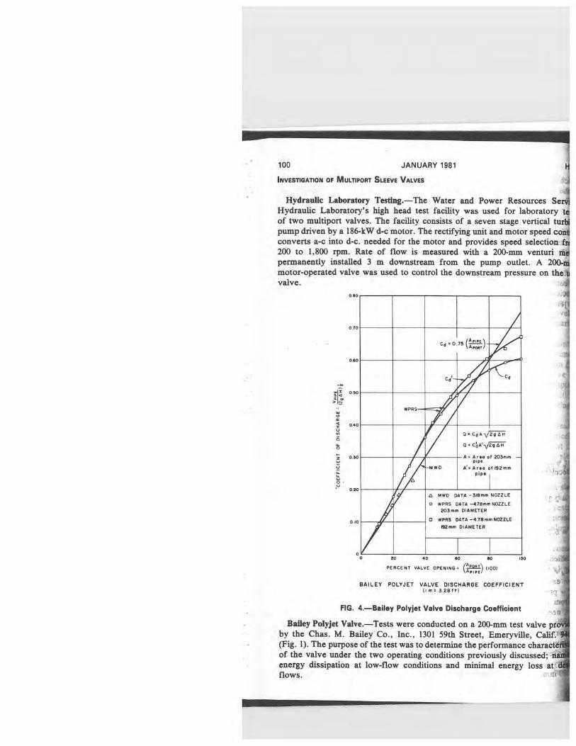
0 0 20 40 SO e0 100
PERCENT VALVE OPENING= \AA (
100) A►1 PE
BAILEY POLYJET VALVE DISCHARGE COEFFICIENT 0 m= 3.28ft)
Cd = 0.75 (A""
A FORT /
Cd C
WPRS —
Q 2QAH
Ca Al 2 AAH
Area of 203mm Pipe
—MIND Al-Area of 192 mm Pipe
MWD DATA —318m. NOZZLE
o WPRS DATA —4.78mm NOZZLE 203mm DIAMETER
❑ WPRS DATA-4.78mm NOZZLE
192mm DIAMETER
Hydraulic Laboratory Testing.—The Water and Power Resources Serf Hydraulic Laboratory's high head test facility was used for laboratory t of two multiport valves. The facility consists of a seven stage vertical turf pump driven by a 186-kW d-c motor. The rectifying unit and motor speed corA converts a-c into d-c. needed for the motor and provides speed selection f; 200 to 1,800 rpm. Rate of flow is measured with a 200-mm venturi mj permanently installed 3 m downstream from the pump outlet. A 200-motor-operated valve was used to control the downstream pressure on thel valve.
FIG. 4. Bailey Polyjet Valve Discharge Coefficient
Bailey Polyjet Valve.—Tests were conducted on a 200-mm test valve pri by the Chas. M. Bailey Co., Inc., 1301 59th Street, Emeryville, Calif: (Fig. 1). The purpose of the test was to determine the performance charactc of the valve under the two operating conditions previously discussed; =ni energy dissipation at low-flow conditions and minimal energy loss at ~ flows.
MULTIPORT SLEEVE VALVES 101
lgntrol for the Bailey valve consists of a cylindrical sleeve located inside N*a chamber of the valve that travels over the ports. Movement of lyy.controls the open port area and, thus, the valve discharge. The flow inward through the 1,835, 4.78-mm ports, then along the inside of the led sleeve into the downstream pipe, which is the same diameter as
W were conducted to determine the discharge coefficient, Cd , for the ky,slve. The discharge coefficient curves based on the 203-mm-diam pipe N"-,..and the 192-mm-diam perforated sleeve area are shown in Fig. 4.
'11,-1,835 ports were the same size and configuration, it would appear .overall valve flow characteristics would be the same as the local flow acristics of each port. This would result in a linear relationship between dve coefficient of discharge Cd and the area ratio: A p..n /A p;a . As indicated 1. 4, this was not the case. Test results conducted by the MWD of Southern irnia (10) on a similar 200-mm polyjet valve are included in Fig. 4. ,the control sleeve is opened, exposing more ports, the flow near the
TABLE 1.-Bailey Polyjet Valve Test Data
_'_ `Valve Q, in V, ~_opening, H,,, in H,, in cubic meters in meters Cavitation Time,
in percent meters meters per second per second index = v' in hours (2) (3) (4) (5) (6) (7)
S 136 2.19 0.066 2.04 0.08 2.0 10 107 5.85 0.122 3.78 0.14 2.0
#. 15 70.1 4.18 0.151 4.66 0.19 2.0 20 46.0 4.15 0.167 5.15 0.30 1.5 30 25.3 4.05 0.171 5.27 0.59 2.0
i (H, - H,)/(H - He); H, = -8.47 m (atmospheric pressure at the Water 1rd Power Resources Service test facility); and Hd = downstream pressure head.
;am end of the perforated sleeve passes the upstream ports in an effort isfy the downstream flow demand. The resultant approach velocity and Ire drop near the upstream ports causes a reduction in the flow through ports. This phenomenon is similar to that which occurs in manifold pipes. evaluate potential cavitation damage to the 200-mm polyjet test valve, side flow surfaces of the ported sleeve were painted with a white concrete 1,compound. In earlier tests concrete curing compound proved to be an pA.,indicator of the location and degree of pitting of a metal surface
,from cavitation bubble collapse. Table 1 presents the test data for j 9,, Cvalve for sleeve openings of 5, 10, 15, 20, and 30%. Pressure head
k~ralve was measured 1.83 m upstream (H) and 1.73 m downstream Prom the valve. The vapor pressure H, at the Water and Power Resources
laboratory elevation is equivalent to -8.47 m of water. high head vertical turbine pump head was designed to deliver a maximum
f pproximately 0.17 m'/s. Therefore, the cavitation damage tests were
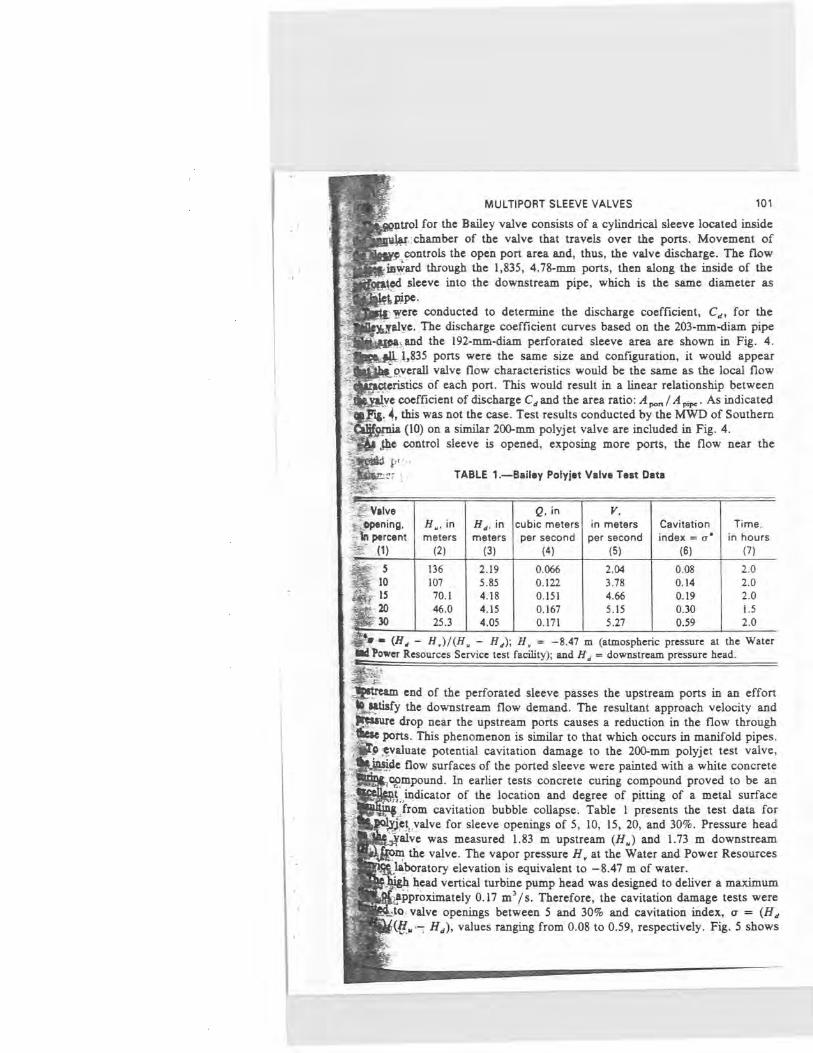
.0. valve openings between 5 and 30% and cavitation index, a = (Hd kj(H„ Hd), values ranging from 0.08 to 0.59, respectively. Fig. 5 shows
102 JANUARY 1981
the resulting paint removal (small pockmarks) on the internal flow surfo of the ported sleeve under the 15% valve opening test condition describes Table 1. The photograph shows cumulative damage from the 5% opening to and including the 15% open level. (The scratch lines on the paint in damaged area were caused by insertion of a mirror for photographs.)
The cavitation damage shown on Fig. 5 is typical of locations where indivi cavities implode near the flow surface. The damage was located in a which extended 152 mm downstream from the ports to 76 mm into the zone, Fig. 1. Although the valve was operated at an extremely low sigma "v (a = 0.08) for the 5% test, there was no apparent cavitation damage. majority of paint removal occurred at the 10 and 15% valve openings. Re;
-
FIG. 5.—Looking Upstream at Ported Sleeve Valve Surface „
indicate that the cavitation damage in the test of this particular valve is, to the quantity of vapor bubbles produced as well as the pressure head relati( The amount of paint removal would increase for greater valve openings sigma values. However, on long pipelines, the majority of the energ; would be dissipated in upstream pipe losses at larger valve openings, re in higher sigma values with less cavitation potential. It is most hkely't critical point, with respect to cavitation damage for polyjet valves a aqueducts with high friction losses, will be in the range of 10 to 159' In general, the polyjet valve performed well when operated within the n~ turer's suggested pressure head ranges.
Horizontal Multiport Sleeve Valves.—Prior to the tests described'

.
0140
120 0.120
- 100 Q 0.10
_'4 E BO W
O.OB
a . C, W 60
Q N 0. 0
ao > 0.04 J
t2f.
Lia 20 0.0
4' - 0
n:~N1U11u11Un11111n1111111111u~ UIIIIIi~~NUlU1111U11UUlllnll/gip Umunll:gl11~~111u1U1n1ifU1 nnilulluH1 !rOMEM.AM MU~IUIIIIIIMMINIM."M 11M UIUUUIMINKINIMM.: ►AMU UnumIn1111D~1,pi1~111U111/,.! lUUlllllUlllll~.'r►̀nl~~llllll►.IIIIIIIII 1 ' •• ' nrlllll~l~n1111►1111111111 IIIn111111~~1111111n►~~~ 161n111111u 111111111.:IIIIIIIIIIn1;~:~iP11m MEN 11111/:11111U111111111~11►'~IIIIIIIIIiIn III~~UUIIIIIIIIINII!'
~!i/1~:11~ff11_11111111
MULTIPORT SLEEVE VALVES 103
rt sleeve valve designs could not be found that fully satisfied the design desired by the Service, that is, a valve that will dissipate high energy
in a low-flow condition and deliver design flows with a minimum energy ~at the valve. Although previous designs function quite well as pressure-
valves, most do not emphasize minimal energy loss when delivering flows.
b 200 mm laboratory test valve discharged into a 1,370 mm-mm 1,220-mm- "ilIing chamber. The basic concept of the valve and stilling chamber is
ted in Fig. 2. Flow enters the valve from the high-pressure side and ged outward through the perforated body of the valve into the stilling
}tier. A cylindrical sleeve located inside the valve body travels over the orated section of the valve, controlling the port area and thus the valve
'f
Y, ge. The flow is discharged into the downstream pipeline at the lower of the stilling chamber.
The concept of a linear relationship between sleeve travel and valve discharge Its also sought as a desired characteristic in the new design. Such a valve
'ttottld provide better control characteristics on long aqueducts where water Lmmer presents a potential problem. Fig. 6 shows ideal valve characteristics
14 0 0035 00335
0.030
0025 E
01020 < Uj
0.015
0 0.010 n
0005
= 50 100 150 200 250 300 350 400 SLEEVE TRAVEL-m
fflw FIG. 6.—Ideal Multijet Sleeve Valve Characteristics
W,-a function of sleeve travel for a 200-mm pipeline where the static upstream : ire head is 137 in. A 200-mm-horizontal multiport sleeve valve with nozzles
slots for ports is proposed. As the valve is opened and the,port area slowly es, the valve discharge increases linearly with sleeve travel. This increase
1Pltlye discharge results in a reduced upstream pressure head due to friction in the long aqueduct. When the valve sleeve has been opened 230 mm, completed the function of a pressure reducing valve and assumes the
9f a low-head-loss control valve. At this point the valve port area increases with sleeve travel but this produces a diminishing increase in discharge the low available pressure head across the valve. When the valve port
equals the 200-mm pipe area, the pressure head differential, OH, has to 1.1 m across the valve, resulting in a discharge coefficient C,
104 JANUARY 1981
Q,;3
A C',
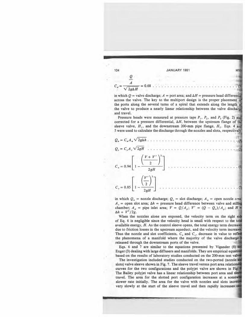
2gOH = 0.68 . . . . . . . . . . . . . . . . . . . . . . . . ...
in which Q = valve discharge; A = port area; and AH = pressure head different across the valve. The key to the multiport design is the proper placement the ports along the several turns of a spiral that extends along the length the valve to produce a nearly linear relationship between the valve dischar and travel.
Pressure heads were measured at pressure taps P„ P2, and P, (Fig. 2) ai corrected for a pressure differential, OH, between the upstream flange 41 sleeve valve, H, , and the downstream 200-mm pipe flange, H2 . Eqs. 4 ai 5 were used to calculate the discharge through the nozzles and slots, respective]
• 'T Q~ = C A„ g . . . .. . . . . . . . . . . . . .. . .. . .. . . ......~
QS = C,A, g . . . . . . . . . . . . . . . . . . . . . . . . . . . . .
~V+V')2]
2
C =0.94 1— 2gH
.................. .(
C, = 0.85 1 — . . . . . . . . . . . . . . . . . . . . . . . . . . . I 2gH
in which Q = nozzle discharge; Q. = slot discharge; A. = open nozzle are A, = open slot area; Ah = pressure head difference between valve and stilli chamber; A p = pipe inlet area; V = Q/AP ; V' = (Q — Q)/AP ; and H Ah + V 2/2g.
When the nozzles alone are exposed, the velocity term on the right si of Eq. 6 is negligible since the velocity head is small with respect to the toy available energy, H. As the control sleeve opens, the total energy term decreas due to friction losses in the upstream aqueduct, and the velocity term increasi Thus the nozzle and slot coefficients, C and C„ decrease in value to refk the phenomena of a manifold where the majority of the valve dischargel released through the downstream ports of the valve. "?*A
Eqs. 6 and 7 are similar to the equations presented by Vigander (8) 4 Enger (3) dealing with large diffusers and manifolds. They are empirical equatid based on the results of laboratory studies conducted on the 200-mm test val'
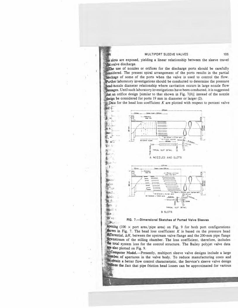
The investigation included studies conducted on the two-ported (nozzle slots) valve sleeve shown in Fig. 7. The sleeve travel versus port area relatic curves for the two configurations and the polyjet valve are shown in Fi The Bailey polyjet valve has a linear relationship between port area and sl travel. The area for the slotted port configuration increases at a some slower rate initially. The area for the valve with nozzles and slots incr' very slowly at the start of the sleeve travel and then rapidly increases
MULTIPORT SLEEVE VALVES 105
dots are exposed, yielding a linear relationship between the sleeve travel ,valve discharge he use of nozzles or orifices for the discharge ports should be carefully sidered. The present spiral arrangement of the ports results in the partial ;kage of some of the ports when the valve is used to control the flow. Sher laboratory investigations should be conducted to determine the pressure d4ozzle diameter relationship where cavitation occurs in large nozzle flow sages. Until such laboratory investigations have been conducted, it is suggested an orifice design [similar to that shown in Fig. 7(b)] instead of the nozzle
cgn be considered for ports 19 mm in diameter or larger (2). ►eta for the head loss coefficient K are plotted with respect to percent valve
1 <3 ••
I 1
18-122mm . $2.1mm snit
41.64mm mites \~=6-7.9mm nes 95mm~
` u r~
TYPICAL SLOT DETAIL .~,. 9
A NOZZLES AND SLOTS
' azmm s~ ~m.r'-s99mm
~6-i]Bmm.12.i— 1 wn uoo In'n
s~
-6-~T6 mm s 2S~mm snh (por~an MI17 r `9-Id 6mm • 19.Imm snn 45 mm
24-5Q9mm s 7.9mm sn~s mm
TYPICAL 5LOT DETAIL
ling (100 x port area/pipe area) on Fig. 9 for both port configurations
vn in Fig. 7. The head loss coefficient K is based on the pressure head
erential, OH, between the upstream valve flange and the 200-mm pipe flange 'nstream of the stilling chamber. The loss coefficient, therefore, includes total system loss for the control structure. The Bailey polyjet valve data also plotted on Fig. 9. A0"uter Model.—Presently, multiport sleeve valve designs include a large lkbes, of apertures in the valve body. To reduce manufacturing costs and 6tam abetter flow control characteristic, the Service's sleeve valve design lZu the fact that pipe friction head losses can be approximated for various

100 e0
60
40
106 JANUARY 1981
flows by using the equation Hj = KQ2, in which K = constant for a par pipeline and Q = CAgH2gH. Using this approach, a computer progn (U.S. customary units) has been developed to locate and space nozzles
0.0 m
0.0547 m=
• • ■■■■■■■■■■MIN
..
■ . . . '
_
■' 1111 ■■
III ■■I ■■■■
PORT AREA -M2
FIG. 8—Sleeve Travel Versus Port Area
...N man== a~Na~N~a~a~ gym
1 M~N MEMMMMMMMMMMMM
MMxxWMMM N~~~~~~~N~~~
-Sleeve with MZZIeS and ii
Na~aZi~i►~~a~ a~ a>,N~N~a~~
~M~M
~a1Ns~l~ ~~~a1s~Nalatial~~ '-
q_N_■NNM M
VALVE OPENING- (POUT AREA ) 100 PIPE AREA
FIG. 9. Head Loss Coefficient
a spiral around the valve body such that a linear change in flow is mai through the zone of the nozzles. As the control sleeve is retracted to more apertures, the number and / or diameter of the nozzles is increas

MULTIPORT SLEEVE VALVES 107
Est diameter nozzle is equal to the wall thickness of the valve body. f' ;point is reached where the computed number of nozzles cannot meet
' ttm spacing requirements along the spiral in a quadrant that is being ted, then the program automatically changes its output from nozzles lected number of longitudinal slots. The length of the slots is computed intervals such that at the final length, full flow is achieved: that is,
L.@the control sleeve is retracted past the end of the last slot (Fig. 7(a)] . erential area, Aq, of each set of nozzles in a quadrant along the spiral
ed by use of the well-known orifice equation, Q = CA 2gAH. change in flow is obtained by setting a uniform rate of change between
aks; hence the change for a quadrant can be calculated. Rewriting rifice equation, we have
,rr Q. (8) E*w 2gAH
uch. Q = the theoretical flow (in cubic feet per second) through the nozzles L on the control sleeve travel from the reference index line (Fig. 7(a)] ; 0.94, a value which remains constant until slots are included in the output;
1 4.32 ft /s2; OH = differential head in feet across the sleeve valve for jtadrant being incremented. (For each quadrant, AH is reduced by the pipe friction for the reach being considered. Since Q is a function of ace from the reference index line and Hj = KQ2, then H = H,,,,;. —j; and A, = the total amount of nozzle area in square feet required to Dow Q. om this relationship, A9 for the quadrant being incremented can be obtained ubtracting the total area, A,,, of the nozzles in the preceding quadrants A,,. Because A will not exactly match with the sum of the areas of the
4es.that can be used in a quadrant, the smaii excess area is added to the dated area for the next quadrant before its number of nozzles is computed. ig physical model test program was used to evaluate the empirical coefficients ;and has produced good agreement with discharges indicated in the computer el. The linear change in Q is maintained until the control sleeve is retracted Lg;zone of the slots. At this point, flow is approximately 82% of the design k3he end result is a valve which can achieve design flow with a much 40tpumber of apertures. It is hoped that physical model testing can be utued to evaluate larger design flows where two or more multiport sleeve epwould be required in a flow control structure. eehanical Considerations.—The heart of the sleeve valve is two concentric Wers. The outer cylinder or body is fixed and contains the regulating ports; 040r, unperforated movable cylinder is the control sleeve. It fits closely K the. body and is moved longitudinally to cover and uncover the ports iftPg regulation of flow. Minimal practical clearances are provided between
9tt;
tand sleeve to control leakage. No seals or packings have been used
1ld-11'e-eeve. A guard valve upstream of the sleeve valve provides tight shutoff o, flow is desired and the sleeve valve is closed. If minimal leakage Unt, piston rings are provided on the sleeve. The Metropolitan Water of_ Southern California designed their valves for tight closure (5,9).
...1-are provided on the end of the sleeve which does not move across
108 JANUARY 1981
the regulating ports and a fixed seal is mounted in the body to seal the C] end of the sleeve when the valve is closed.
The valve ports can be varied in size, type, and spacing to meet a W range of requirements. According to MWD round nozzles are limited ifi3i as their diameter cannot be larger than the body shell thickness beca1Q. changes which occur in jet characteristics. Because of the limitation on a large number of nozzles is required. Ports can be machined as slotsiA the same taper as the round nozzles. The width of the slots has the sad limitations as the diameter of the nozzles with respect to cavitation dami and the length is limited by the physical strength of the body shell. Bec81 of the taper, these ports must be reamed from the inside of the cylinM body. This is a difficult and expensive machining process. A 200-mm 'Ve is considered the smallest that can be machined from the inside.
In river or reservoir outlet work installations where the water may debris large enough to plug the nozzle-type ports, ports that are designed sharp-edged orifices are utilized. These ports have parallel sides for the f 1.5 to 7 mm of depth from the inside of the body [Fig. 7(b)] . To eliini any possibility of cavitation on the sides of the port, the remainder oft port is flared out at a 45° angle.
The size and shape of the ports can be specified to suit specific requirema Port shapes have been made round, oblong, and longitudinal. In general,' size of a port is limited by the physical strength of the body shell. Howe the larger the port, and in turn the jet, the greater the outward dis (perpendicular to the valve body) that is required to dissipate the enei the jet. For this reason, the ports should be kept as small as practicable consW with the size of expected debris that must be passed.
Port size and spacing may be varied to meet specific hydraulic requirema As noted previously, valves used in long municipal-industrial pipelines benefits from linear discharge characteristics even though the effective ew head at the valve drops rapidly as the discharge increases. It has already`. shown that this requirement can be easily met by varying spacing anii of the nozzles and, when effective head drops sufficiently, changing to , This general principle can be used for other discharge characteristics. example, valves requiring fine regulation of small off-season discharge ca$ a few small ports as required for the off-season releases. The remaind the ports can be longer and spaced closer together to give needed reg` of normal releases with minimum sleeve travel. As port size increases, necessary to place ports diametrically opposite to maintain hydraulic' of the valve.
The sleeve valve lends itself to many physical arrangements. The most e and straightforward is the horizontal valve of the general type used in the laboratory test and shown in Fig. 2. In this type, the stem attached control sleeve is extended downstream through packings to the valve " o Thus all moving parts of the sleeve are downstream of and unaffected) water flow. The sleeve is hydraulically balanced. The only unbalance hydraulic load on the valve stem. Since this stem load and friction-, only loads to be overcome, the operating mechanisms can be relatively' "
Sleeve valves are adaptable to many types of operating mechanis Service has used a gear type with torque-limiting switches, hydraulic cy

MULTIPORT SLEEVE VALVES 109
01JVven a hand-operated gear lift for a remote installation without power. rye` vertical arrangement has been used for some valves with the flow being
IIIIjJjOhged-downward into a square stilling well (Fig. 10). This is a good mngement for valves with large ports as the distance required to dissipate
I►e jet energy is much greater. The bottom of the stilling well and the lower walls should be steel lined and the well sized to allow jet velocities as high M 12 m/s to impinge on the steel liner. The stilling well will very effectively 6jipate the remaining energy of the jets. However, with this arrangement the incoming water flow must pass through a 90° elbow and the valve operator
s2ci`.>
~a8
ail
st,
Mon
FIG. 10.—Typical Multiport Sleeve Valve in Vertical Stilling Well
ted on top of the elbow. Thus the control stem is in the water passage e 'water must flow through the inside of the control sleeve. The valve
must be streamlined to impede water flow as little as practical and vide adequate support to the stem. The Service's experience has shown brations can cause fatigue and breaking of a stem. Flow velocity through
w and sleeve must be kept low and, when at maximum valve opening, not exceed 11 m/s.
the mechanical standpoint, sleeve valves are fairly simple devices. or. there are features that prevent them from being classified as inexpen-

110 JANUARY 1981
sive. The body; sleeve, and stem must be made from corrosion-resistant matq The sleeve and body must be carefully and closely fitted. As noted: bI the ports are difficult and expensive to machine. The stainless steel bodl creates a machining problem.
PROTOTYPE INSTALLATIONS AND EXPERIENCE
i
A 356-mm-diam prototype horizontal multiport sleeve valve has 4b installed in the Deep Red Run rate-of-flow control station near the end of Frederick Aqueduct of the Service's Altus Project in Oklahoma. The v; is designed for Q = 0.23 m' / s with a static head at no flow of 70 m. Fi the Frederick regulating tank which is located upstream of the valve, C is a gravity flow-pressure pipeline consisting of 5.52 km of 610-mm pipe, km of 458-mm pipe, and 3.8 km of 406-mm pipe. The multiport sleeve v has allowed the designers to use one rate-of-flow control station in lief four which would incorporate butterfly valve type rate-of-flow controllerl is estimated that savings resulting from elimination of three flow control stat are well above $200,000. Field testing of the prototype valve is planned the near future.
Several large (1,372 mm) multiport sleeve valves (Fig. 10) have been des4 for control of flow in vertical stilling wells. These valves have circula elliptical-shaped ports with diameters up to 305 mm. Installations are plat for the Mt. Elbert Aqueduct in Colorado and Sugar Pine Dam River of works in California.
CONCLUSIONS
1. Laboratory tests were conducted on a 200-mm polyjet valve. The v performed well when operated within the manufacturer's suggested pre$, head ranges. However, the multiport sleeve valve design will be used by Water and Power Resources Service for those applications where opera may be intermittently outside the suggested pressure head range for the pa valve. ~~i
2. Physical and mathematical models have been used to develop a horizA multiport sleeve valve design for use as a flow controller on long aqua systems. ,.
3. The design of the multiport sleeve valve is quite versatile and C& used in a wide variety of flow regulation situations. j
APPENDIX I.—REFERENCES
1. Albertson, M. L., Dai, Y. B., Jensen, R. A., and Rouse, H., "Diffusion of Sul Jets," Transactions, ASCE, Vol. 115, Paper No. 2409, 1950, p. 639.
2. Burgi, P. H., "Hydraulic Model Studies of Vertical Stilling Wells," REC-Ei Bureau of Reclamation, Denver, Colo., Feb., 1973.
3. Enger,-M. C., and Levy, M. L., "Pressure in Manifold Pipes," Journal A Water Works Association, Vol. 21, Mar., 1929, p. 659.
4. Falvey, H. T., "Hydraulic Model Studies of the Wanship Dam Vertical Stillin Weber Basin Project, Utah," Report No. Hyd481, Bureau of Reclamation;' Colo., Jan., 1962.
5. Johnson, D., "Sleeve Valves," Institute on Control of Flow in Closed ` E

MULTIPORT SLEEVE VALVES 111
redo State University, Fort Collins, Colo., Aug., 9-14, 1970, (published 1971). E., "The Submerged Discharge Valve," Glenfteld Gazette, No. 229, Feb.,
H., "Jet Diffusion and Cavitation," Journal of the Boston Society of Civil eers, Vol. 53, No. 3, 1966. der, S., Elder, R. A., and Brooks, N. H., "Internal Hydraulics of Thermal
e Diffusers," Journal of the Hydraulics Division, ASCE, Vol. 96, No. HY2, Paper 7085, Feb., 1970, pp. 509-527.
litson, W. W., "Evolution of Multijet Sleeve Valve," Journal of the Hydraulics n, ASCE, Vol. 103, No. HY6, Proc. Paper 13006, June, 1977, pp. 617-6631. W. P., "Test and Evaluation of 8-inch Bailey Polyjet Valve," Report No.
4, Metropolitan Water District of Southern California, Oct., 1970. bvdjevich, V. M., "Diffusion of Slot Jets with Finite Orifice Length-Width Ratios," lorado State University Hydraulics Paper No. 2, Dec., 1965.
Ii —NOTATION
symbols are used in this paper:
nozzle port area; pipe inlet area;
= quadrant port area; = slot port area; = total port area; = slot width;
d = discharge coefficient; C = nozzle discharge coefficient;
= slot discharge coefficient; D = circular port diameter;
= gravitational acceleration; = pressure head differential across port; = pressure head differential between valve and stilling chamber; = valve discharge; = nozzle discharge;
' = slot discharge; Y. = Q /A,;
= jet exit velocity; = jet center line velocity at distance X;
-r = (Q — QXA,; = distance from exit port along jet center line; and
' = cavitation index.