Embed Size (px)
Citation preview

Multiport Network Method and Using It for Accurate Design of Square Spiral Antennas
Saman Rajebi School of Fields & Waves
Dept. of Electrical & Electronic Eng. Urmia University
of IRAN
Changiz Ghobadi, Javad Nooriniya School of Fields & Waves
Dept. of Electrical & Electronic Eng. Urmia University
of IRAN
Abstract: Interest increasing to use of microstrip technology in fuzzy array systems and possibility of using millimeter-wave arrays have caused development of CAD1techniques for accurate design of patches and microstrip arrays be necessary. Multiport network method is one of the best methods to design and analyse antennas and microstrip patch arrays. On other hand, square spiral antennas have the merits of not only wide bandwidth and circular polarization but also compact size which makes them good candidate for mobile receiver applications. In this paper, first, MNM1 is introduced and then a microstrip square spiral antenna is designed accurately and results are presented.
Keywords: Multiport network, segmentation, desegmentation
1 Introduction We can find a regular solution for wave equation and boundary conditions at the slot with isotropic region by using various analytic and numerical techniques. Choosing one of this techniques depend on most effective using of computer. Foe example if the slot has a simple geometry, Greens method and special mode expansion method are very suitable methods. If slot geometry is not too simple and not too complex (arbitrary) and its geometry compounded by simple geometry segments (their Green’s function is known), we use the dividing into segments method (segmentation). By using the dividing into segments method, we can obtain whole characteristics of
called segments compounding (desegmentation), for simplify of final geometry analytic, some of simple geometries with known Green’s functions add to primary geometry. If geometry of the slot is arbitrary, we can not use any segment and desegment methods. In this case, numerical techniques such as moment method are used [1]. 2 Theoretical Studies If geometry of the slot is compounded from simple geometries such as rectangle, triangle or circle, we can use MNM method. First, the Green’s function (that it calculates voltage of each point of the slot in effect of one current source as excitation in other point) is obtained analytically. With appointing locate of ports. The slot
Proceedings of the 5th WSEAS Int. Conf. on Software Engineering, Parallel and Distributed Systems, Madrid, Spain, February 15-17, 2006 (pp180-186)

1s z
vJ aj d nωµ
∂=
∂
uuvcharacteristic impedance matrix can be obtained by using the Green’s functions. Thus, port specifying is introduced first.
To arrive at the multiport impedance matrix for the planar circuit of the patch, the periphery of the patch is first divided into a number of edges, each of which is then classified as radiating type or nonradiating type. The classification is based on the observation that a radiating edge is associated with slow field variation along its length. The non radiating edge, on the other hand, should have an integral multiple of half_wave variations along the edge. Then each edge of each segment is divided to several ports. Each port width is kept less than or equal to / 20gλ to optimize the discretization error and efficiency [2].
If the slot is excited at each arbitrary point 0 0( , )x y by current density zJ at z direction (in the slot region), wave equation can be modified to following:
2 2( )T zk v j dJωµ∇ + = − (1) where
2 22
2 2T x y∂ ∂
∇ = +∂ ∂
and k ω µε=
when the slot is feed from edge or by a strip line, zJ represent artificial RF current density that vertically applied to circuit. In this case, current density
(2 / )nvJ j dn
ωµ ∂⎡ ⎤=⎢ ⎥∂⎣ ⎦ that applied to
coupling ports is replaced by vertical feeder (in z direction) and magnetic wall
condition 0vn∂
=∂
. Equivalent artificial
surface current sJuuv
(in z direction) is written to following form:
(2)
By using linear current source 0( )r rδ − , located at 0r r= , in z direction and followed under the patch, Green’s function is obtained by solving of:
2 20 0( ) ( | ) ( )T k G r r j d r rωµ δ∇ + = − − (3)
and with the boundary condition:
0Gn
∂=
∂ (4)
If electric current source 0 0( , )zJ x y is located at 0 0( , )x y and in z direction, the voltage of each point of the slot, ( , )v x y , is related to source current through 2_dimension impedance Green’s function:
0 0 0 0 0 0( , ) ( , | , ) ( , )zD
v x y G x y x y J x y dx dy= ∫∫
(5) where D represents the structure two dimension region surrounded by magnetic walls. When current source is only applied to structure periphery, the voltage v in the periphery can be written as:
0 0 0( ) ( | ) ( )scv s G s s J s ds= ∫ (6)
Where s and 0s are the local spans on the periphery. Linear current 0( )sJ s represent several separate parts on the periphery at coupling ports. Therefore:
0 0 0( ) ( | ) ( )j
swj
v s G s s J s ds=∑∫ (7)
Proceedings of the 5th WSEAS Int. Conf. on Software Engineering, Parallel and Distributed Systems, Madrid, Spain, February 15-17, 2006 (pp180-186)
That summation is accomplished on all the coupling ports and jw represents width of Jth coupling port. With knowing
v
p vi dsj d nωµ
∂=
∂∫ and
1s z
vJ aj d nωµ
∂=
∂
uuv following formula is
obtained:
0 0( )j
j zwi p J s ds= ∫ (8)
By assuming that width of coupling ports are too small that current density
sJ is uniform along it, the following relation is obtained from earlier formula:
0( ) js
for jth port j
iJ s
pw= (9)
(For microstrip slots 1p = , and for strip line slots 2p = ) By replacing (9) in (8):
0 0( ) ( | )j
j
wj j
iv s G s s ds
pw=∑ ∫ (10)
For calculating the voltage of ith coupling port, average of ( )v s is determined:
1 ( )i
i wi
v v s dsw
= ∫ (11)
By dividing both hand of this relation to ii , impedance matrix components of slot is calculated in following form:
0 01 ( | )
j iij w w
i j i
z G s s ds dspw w
=∑ ∫ ∫ (12)
Under patch fields don’t vary in z direction because thickness of substrate is not comparable with wavelength
( d λ<< ), in other hand, electric field
only have z component and 0zEz
∂=
∂,
therefore:
( , ) ( , )zv x y E x y d= − (13)
After specifying impedance matrix Z of
slot, scattering matrix S should be
specified by following formula:
0 0 0 0( )( )S Y Z Z Z Z Z= − + (14)
Where 01 02 0, ,..., nZ Z Z represent
normalized impedances in various ports
of the slot.
2.1 Segmentation Major opinion in this method is dividing a large slot to simple segments that they have regular geometries with known Green’s functions. Segmentation of a square spiral antenna has been shown in figure2. After segmentation and calculating impedance matrixes for each segment, the overall Z matrix of the given structure should be calculated For this, the ports of the segments (to be combined) are separated into external ( ρ ) ports and connected (c) ports. The connected ports are equally divided into two groups labeled q and r ports such that q ports are the connected ports of one segment and r ports are the corresponding connected ports of the other segment, to be combined. Based on the labeling, the Z matrix of the combination can be written as:
Proceedings of the 5th WSEAS Int. Conf. on Software Engineering, Parallel and Distributed Systems, Madrid, Spain, February 15-17, 2006 (pp180-186)

. p ppp pq pr
q qp qp qr q
rp rq rrr r
V iZ Z ZV Z Z Z i
Z Z ZV i
⎡ ⎤ ⎡ ⎤⎡ ⎤⎢ ⎥ ⎢ ⎥⎢ ⎥=⎢ ⎥ ⎢ ⎥⎢ ⎥⎢ ⎥ ⎢ ⎥⎢ ⎥⎣ ⎦⎢ ⎥ ⎢ ⎥⎣ ⎦ ⎣ ⎦
uuv uv
uuv uv
uuv uv
where pV , qV , rV and pi , qi , ri are the vectors corresponding to RF port voltages and port currents, respectively, and the ppZ and so on values are the impedance submatrices. Because ports q and ports r are respective ports of two physically separate segments (that are being connected together), submatrices
qrZ and rqZ are identically equal to zero. and the impedance matrix of the combination as[3]:
1[ ] [ ] [ ][ ] [ ]p pp pq pr qq rr rp qpZ Z Z Z Z Z Z Z−= + − + −
(15)
2.2 Extension of Radiating Edges For considering effect of leakage fields, extension of radiating edges has been suggested.[4]. Amount of this extension is equal to:
1 12tan tan ( )4 2
ww
βδ βδ− −∆ +⎧ ⎫= ⎨ ⎬∆ +⎩ ⎭ (16)
where 02 2ln(2) , , g
g r
d λπβ λπ λ ε
∆ = = =
w is the width of extended side and 2d is distance between two ground planes. This extension is shown in figure 2.b.
2.3 Calculation of Radiation Pattern In multiport network method, radiation power of patch is obtained by magnetic wall concept. Induced magnetic current
density at magnetic wall is obtained from
δ Figure1 Patch antenna without extended radiating edge and Patch antenna with extended radiating edge and leakage fields elimination
$M n E= ×uuv uv
(17) Where $n is vertical vector of magnetic wall. If Muuv
is constant along the width of port, far field electric potential is obtained [4]:
0 0
0 0
' 'cos0
1
' 'cos0
1
( ') ( ')4
( ') ( ')4
x
i
y
i
mjk r jk r
x ii c
njk r jk r
y ii c
F e M r e dl rr
F e M r e dl rr
ζ
ζ
επ
επ
−
=
−
=
=
=
∑ ∫
∑ ∫
(18) where
xiM and
yiM are magnetic current
vector components in x and y directions sequently, and ζ is angle between these two vector. ζ equals to following formula in terms of θ andϕ :
cos sin .cos( ')ζ θ ϕ ϕ= − (19) Finally, following relations are obtained for electrical field:
0
0
E jk F
E jk Fθ ϕ
ϕ θ
=
= − (20)
Proceedings of the 5th WSEAS Int. Conf. on Software Engineering, Parallel and Distributed Systems, Madrid, Spain, February 15-17, 2006 (pp180-186)

2.4. Green’s Function for a Rectangle [4] Green’s function for a rectangular can be written as:
0 0
0 02 2 2
0 0
( , | , )
cos( ) cos( ) cos( ) cos( )m n x y x y
n m x y
j dG x y x yabk x k y k x k y
k k k
ωµ
σ σ∞ ∞
= =
= ×
+ −∑∑ (21)
where a and b are sides of rectangle
and x ym nk and ka bπ π
= = . Also:
1 02i
if iotherwise
σ=⎧
≈ ⎨⎩
3 Design and Simulated Results In this section we consider a square spiral antenna shown in figure2 in frequency range of 8 GHz to 12 GHz. Properties of this antenna is represented in figure. Dielectric constant of substrate is 2.7( 2.7rε = ) and its height is d=1.6mm and loss tangent of dielectric is δ =0.0015. First, various characteristics of the slot is simulated by full-wave planar circuits simulator “Ansoft 1.1”, then same characteristics is calculated by multiport network method has been programmed in “Matlab7”. Finally, both types of results are compared to each other. For this, first the Zpq of a rectangular geometry should be calculated. Result of calculation can be written as [4]:
2 2 2
0 0
( , ) ( , ) /( )
pq
m n mn p p mn q q x ym n
j dZab
x y x y k k k
ωµ
σ σ φ φ∞ ∞
= =
= ×
+ −∑∑ (22)
where for ports located in x direction:
( , ) cos( ) cos( )2x
mn x ykx y k x k y sinc ωφ ⎡ ⎤= ⎢ ⎥⎣ ⎦
and for ports located in y direction:
( , ) cos( )cos( )2y
mn x y
kx y k x k y sinc
ωφ
⎡ ⎤= ⎢ ⎥
⎣ ⎦
and
2 20
1 0,
2 0
, , (1 tan )
m
x y r
mm
m nk k k ja b
σ
π π ω µε ε δ
=⎧= ⎨ ≠⎩
= = = −
In figure 3.b, square spiral antenna is segmented to seven part and all ports (p, q, r) are specified. Also, in this figure extended radiation edges are shown. Characteristics of the square spiral antenna that are inspected include S11, Zin, Swept Gain, Radiation Pattern and voltage amplitude of ports. Voltage amplitude at number of ports is calculated by equation (10) and result is shown in figure7. Corresponding to this figure, voltage at nonradiating edges has casinos variations but at radiating edges, voltage is constant.
Proceedings of the 5th WSEAS Int. Conf. on Software Engineering, Parallel and Distributed Systems, Madrid, Spain, February 15-17, 2006 (pp180-186)

(a)
(b)
Figure 2 (a) Square spiral antenna schematic and (b) segments of square spiral antenna made
ready for multiport network method analysis Swept Gain and Radiation Pattern of antenna are shown in figures 4 and 5. These figures represent results from Ansoft. Figures 5 and 6 represent the both results from Ansoft and multiport network method. By comparing the results, accurate of results from multiport network method is confirmed.
4. Conclusion Simulated results from Ansoft and Multiport Network Method represent very good ability of the Multiport Network Method in accurate designing of microstrip patch antennas. Also showing amplitude distribution at antenna edges (ports) produces good understanding about antenna operation. References [1] T. Itoh, “Numerical Techniques of Microwave and Millimeter-Wave Passive Structures,” John Wiley & Sons, 1989. [2] V. Palanisamy and R. Garg, “Analysis of Arbitrary Shaped Microstrip Patch Antennas Using Segmentation Technique and Cavity Model,” IEEE Trans. Antennas Propagat, Vol. AP-34, 1986, pp1208-1213. [3] P .C. Gupta et al, “Computer Aided Design of Microwave Circuits;” 1981, Dedham (Mass, U.S.A), pp356-357. [4] J. R. James, and p. s. Hall, “Handbook of Microstrip Antennas,” London: Peter Peregrinus Ltd, 1989. [5] T. Okashi and T. Takeuchi, “Analysis of Planar Circuits by Segmentation Method,” Electronics & Communications in Japan Vol. 58-b, 1975, pp.71-79.
Proceedings of the 5th WSEAS Int. Conf. on Software Engineering, Parallel and Distributed Systems, Madrid, Spain, February 15-17, 2006 (pp180-186)
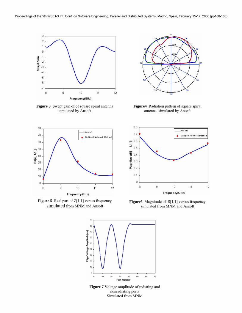
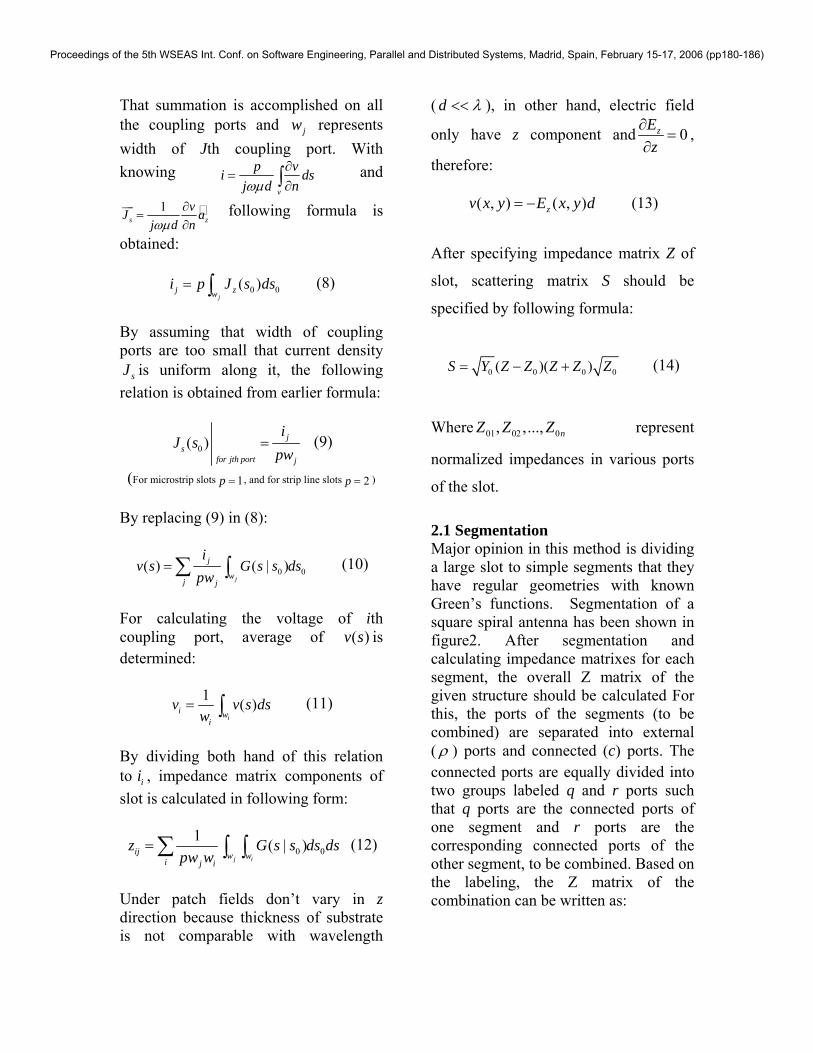
Figure 3 Swept gain of of square spiral antenna
simulated by Ansoft
Figure 5 Real part of Z[1,1] versus frequency
simulated from MNM and Ansoft
Figure4 Radiation pattern of square spiral antenna simulated by Ansoft
Figure6 Magnitude of S[1,1] versus frequency simulated from MNM and Ansoft
Figure 7 Voltage amplitude of radiating and nonradiating ports
Simulated from MNM
Proceedings of the 5th WSEAS Int. Conf. on Software Engineering, Parallel and Distributed Systems, Madrid, Spain, February 15-17, 2006 (pp180-186)