Embed Size (px)
Citation preview

Multiplied magnetoelectric effect in multi-faceted magnetoelectric compositeZ. J. Zuo, D. A. Pan, J. Lu, S. G. Zhang, J. J. Tian, L. J. Qiao, and A. A. Volinsky Citation: Applied Physics Letters 104, 032906 (2014); doi: 10.1063/1.4863056 View online: http://dx.doi.org/10.1063/1.4863056 View Table of Contents: http://scitation.aip.org/content/aip/journal/apl/104/3?ver=pdfcov Published by the AIP Publishing
This article is copyrighted as indicated in the article. Reuse of AIP content is subject to the terms at: http://scitation.aip.org/termsconditions. Downloaded to IP:
130.75.239.101 On: Wed, 26 Mar 2014 09:50:26
Multiplied magnetoelectric effect in multi-faceted magnetoelectric composite
Z. J. Zuo,1 D. A. Pan,1,a) J. Lu,2 S. G. Zhang,1 J. J. Tian,1 L. J. Qiao,1 and A. A. Volinsky3
1Institute of Advanced Materials and Technology, University of Science and Technology Beijing,Beijing 100083, China2State Key Laboratory of Magnetism, Institute of Physics, Chinese Academy of Science, Beijing 100190, China3Department of Mechanical Engineering, University of South Florida, Tampa, Florida 33620, USA
(Received 21 December 2013; accepted 9 January 2014; published online 23 January 2014)
A four-faceted magnetoelectric (ME) composite consisting of one cuboid bonded Terfenol-D
composite and four plates of Pb(Zr,Ti)O3 (PZT) was fabricated. The ME voltage coefficients were
measured along the length direction of the composite when PZT plates were parallelly or serially
connected. Results show that the ME voltage coefficient remains almost the same when increasing
the number of PZT in parallel mode. By contrast, the ME voltage coefficient increases
multiplicatively with the increasing of the number of PZT in serial mode. This multi-faceted
structure scheme offers an effective approach to improving ME effect and downsizing the ME
devices. VC 2014 AIP Publishing LLC. [http://dx.doi.org/10.1063/1.4863056]
Magnetoelectric (ME) effect represents the ability of a
certain class of materials to convert magnetic energy to elec-
tric energy, and vice versa. This energy conversion ability
makes the ME materials the promising candidates for various
potential applications, such as energy harvester,1,2 current
and magnetic field sensors,3–5 and microwave devices.6–8
Besides the single phase magnetoelectric compounds
(Cr2O3, Ca3CoMnO6, hexagonal Ho1�xDyxMnO3),9–11 ME
composites have attracted much attention in recent years.
ME composite with bi-layered laminates, tri-layered lami-
nates, disk-ring, and various other combining configurations
between different piezoelectric and piezomagnetic compo-
nents have been developed.12–15
Giant magnetostrictive material (GMM) based ME com-
posites consisting of Terfenol-D alloy or Terfenol-D com-
posite have been extensively investigated.16–20 The ME
voltage coefficient at resonance frequency can be up to 100
times as high as that at sub-resonance frequencies.21 To
broaden the response frequency, Wan et al. fabricated and
measured a combined structure where several Terfenol-
D/epoxy- Pb(Zr,Ti)O3 (PZT) bi-layered composites were
connected in parallel and series. There appear different reso-
nant frequencies and phase angles when changing the size of
the ME composites. The combined structure showed a much
wider frequency response to external field than the single
bi-layered structure. However, the ME effect reduced at
the resonant frequency due to the shunt capacitance and
current loss.22 In the present study, a ME composite with
multi-faceted structure scheme was proposed. Specifically,
the four-faceted Terfenol-D/Pb(Zr,Ti)O3(PZT-5H) ME com-
posite consisting of one cuboid bonded Terfenol-D compos-
ite and four plates of PZT has been fabricated. The ME
effect of this kind of composite has been further improved
by employing the multi-faceted structure scheme.
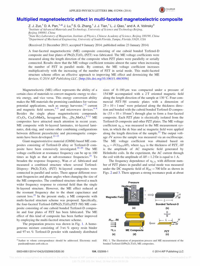
The preparation process was shown in Fig. 1. A homo-
geneous mixture consisting of 3 wt. % epoxy resin binder
and 97 wt. % Terfenol-D powder with randomly distributed
sizes of 0–180 lm was compacted under a pressure of
154 MP accompanied with a 2 T oriented magnetic field
along the length direction of the sample at 130 �C. Four com-
mercial PZT-5H ceramic plates with a dimension of
25� 10� 1 mm3 were polarized along the thickness direc-
tion and bonded with the cuboid bonded Terfenol-D compos-
ite (33� 10� 10 mm3) through glue to form a four-faceted
composite. Each PZT plate is electrically isolated from the
Terfenol-D composite and other PZT plates. The ME voltage
coefficient aE,31 was measured in the ME measurement sys-
tem, in which the dc bias and ac magnetic field were applied
along the length direction of the sample.23 The output volt-
age dV across the sample was measured via an oscilloscope.
The ME voltage coefficient was obtained based on
aE,31¼ dV/(tPZTdH), where tPZT is the thickness of PZT, dHis the amplitude of AC magnetic field generated by
Helmholtz coils. In the experiment, the AC current through
the coil with the amplitude of dH¼ 1.2 Oe is equal to 1 A.
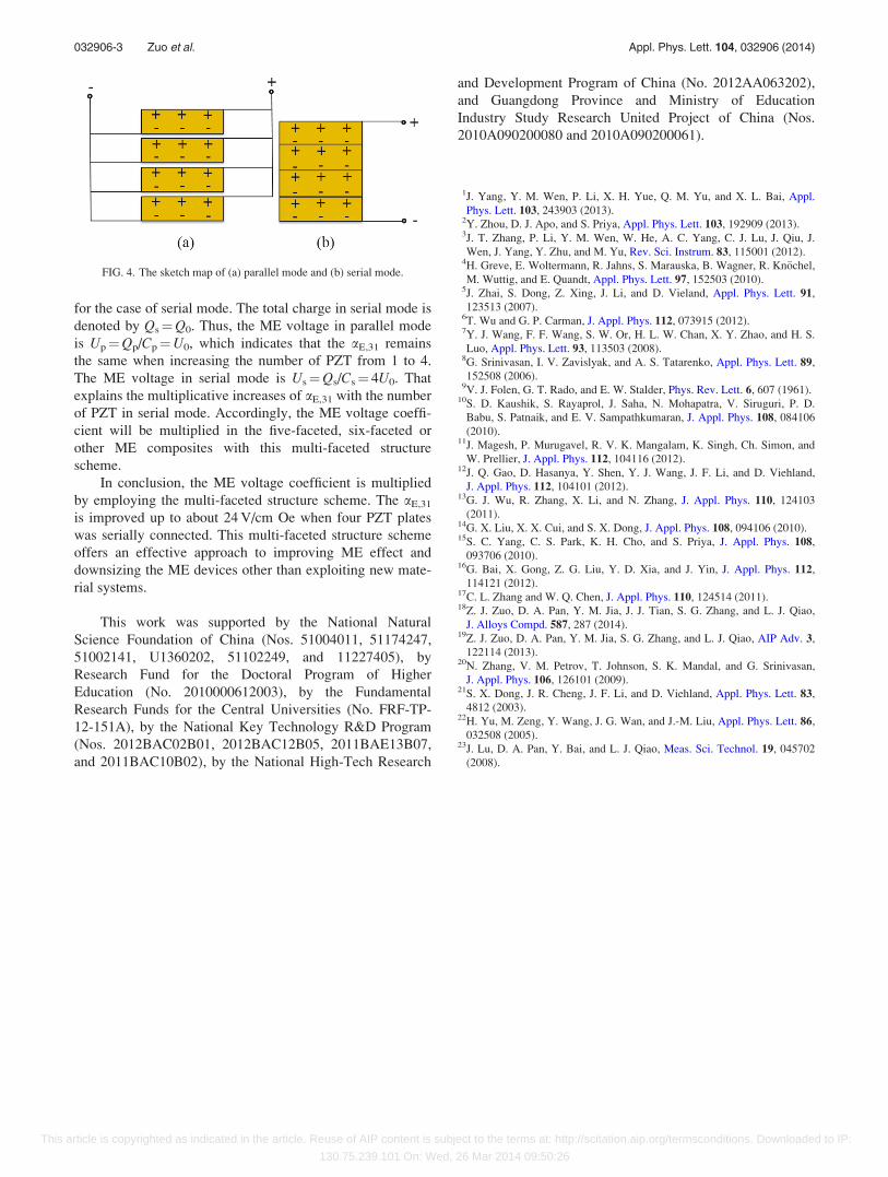
The frequency dependence of aE,31 with different num-
ber of PZT plates in parallel and serial mode was measured
under the DC magnetic field of HDC¼ 700 kOe as shown in
Figs. 2 and 3. There appears a strong resonance peak at about
FIG. 1. The illustration of preparation process and ME measurement of the
bonded Terfenol-D/Pb(Zr,Ti)O3 ME composites.
a)Author to whom correspondence should be addressed. Electronic mail:
0003-6951/2014/104(3)/032906/3/$30.00 VC 2014 AIP Publishing LLC104, 032906-1
APPLIED PHYSICS LETTERS 104, 032906 (2014)
This article is copyrighted as indicated in the article. Reuse of AIP content is subject to the terms at: http://scitation.aip.org/termsconditions. Downloaded to IP:
130.75.239.101 On: Wed, 26 Mar 2014 09:50:26
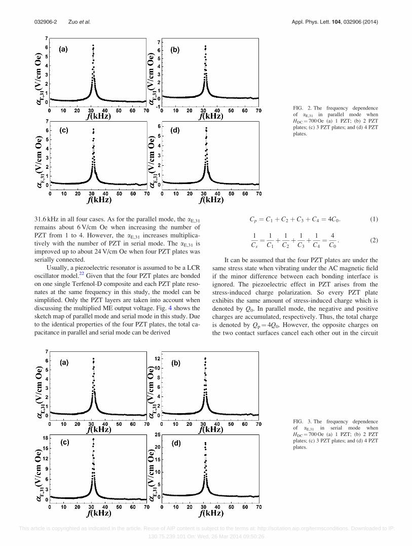
31.6 kHz in all four cases. As for the parallel mode, the aE,31
remains about 6 V/cm Oe when increasing the number of
PZT from 1 to 4. However, the aE,31 increases multiplica-
tively with the number of PZT in serial mode. The aE,31 is
improved up to about 24 V/cm Oe when four PZT plates was
serially connected.
Usually, a piezoelectric resonator is assumed to be a LCR
oscillator model.22 Given that the four PZT plates are bonded
on one single Terfenol-D composite and each PZT plate reso-
nates at the same frequency in this study, the model can be
simplified. Only the PZT layers are taken into account when
discussing the multiplied ME output voltage. Fig. 4 shows the
sketch map of parallel mode and serial mode in this study. Due
to the identical properties of the four PZT plates, the total ca-
pacitance in parallel and serial mode can be derived
Cp ¼ C1 þ C2 þ C3 þ C4 ¼ 4C0: (1)
1
Cs¼ 1
C1
þ 1
C2
þ 1
C3
þ 1
C4
¼ 4
C0
: (2)
It can be assumed that the four PZT plates are under the
same stress state when vibrating under the AC magnetic field
if the minor difference between each bonding interface is
ignored. The piezoelectric effect in PZT arises from the
stress-induced charge polarization. So every PZT plate
exhibits the same amount of stress-induced charge which is
denoted by Q0. In parallel mode, the negative and positive
charges are accumulated, respectively. Thus, the total charge
is denoted by Qp¼ 4Q0. However, the opposite charges on
the two contact surfaces cancel each other out in the circuit
FIG. 3. The frequency dependence
of aE,31 in serial mode when
HDC¼ 700 Oe (a) 1 PZT; (b) 2 PZT
plates; (c) 3 PZT plates; and (d) 4 PZT
plates.
FIG. 2. The frequency dependence
of aE,31 in parallel mode when
HDC¼ 700 Oe (a) 1 PZT; (b) 2 PZT
plates; (c) 3 PZT plates; and (d) 4 PZT
plates.
032906-2 Zuo et al. Appl. Phys. Lett. 104, 032906 (2014)
This article is copyrighted as indicated in the article. Reuse of AIP content is subject to the terms at: http://scitation.aip.org/termsconditions. Downloaded to IP:
130.75.239.101 On: Wed, 26 Mar 2014 09:50:26
for the case of serial mode. The total charge in serial mode is
denoted by Qs¼Q0. Thus, the ME voltage in parallel mode
is Up¼Qp/Cp¼U0, which indicates that the aE,31 remains
the same when increasing the number of PZT from 1 to 4.
The ME voltage in serial mode is Us¼Qs/Cs¼ 4U0. That
explains the multiplicative increases of aE,31 with the number
of PZT in serial mode. Accordingly, the ME voltage coeffi-
cient will be multiplied in the five-faceted, six-faceted or
other ME composites with this multi-faceted structure
scheme.
In conclusion, the ME voltage coefficient is multiplied
by employing the multi-faceted structure scheme. The aE,31
is improved up to about 24 V/cm Oe when four PZT plates
was serially connected. This multi-faceted structure scheme
offers an effective approach to improving ME effect and
downsizing the ME devices other than exploiting new mate-
rial systems.
This work was supported by the National Natural
Science Foundation of China (Nos. 51004011, 51174247,
51002141, U1360202, 51102249, and 11227405), by
Research Fund for the Doctoral Program of Higher
Education (No. 2010000612003), by the Fundamental
Research Funds for the Central Universities (No. FRF-TP-
12-151A), by the National Key Technology R&D Program
(Nos. 2012BAC02B01, 2012BAC12B05, 2011BAE13B07,
and 2011BAC10B02), by the National High-Tech Research
and Development Program of China (No. 2012AA063202),
and Guangdong Province and Ministry of Education
Industry Study Research United Project of China (Nos.
2010A090200080 and 2010A090200061).
1J. Yang, Y. M. Wen, P. Li, X. H. Yue, Q. M. Yu, and X. L. Bai, Appl.
Phys. Lett. 103, 243903 (2013).2Y. Zhou, D. J. Apo, and S. Priya, Appl. Phys. Lett. 103, 192909 (2013).3J. T. Zhang, P. Li, Y. M. Wen, W. He, A. C. Yang, C. J. Lu, J. Qiu, J.
Wen, J. Yang, Y. Zhu, and M. Yu, Rev. Sci. Instrum. 83, 115001 (2012).4H. Greve, E. Woltermann, R. Jahns, S. Marauska, B. Wagner, R. Kn€ochel,
M. Wuttig, and E. Quandt, Appl. Phys. Lett. 97, 152503 (2010).5J. Zhai, S. Dong, Z. Xing, J. Li, and D. Vieland, Appl. Phys. Lett. 91,
123513 (2007).6T. Wu and G. P. Carman, J. Appl. Phys. 112, 073915 (2012).7Y. J. Wang, F. F. Wang, S. W. Or, H. L. W. Chan, X. Y. Zhao, and H. S.
Luo, Appl. Phys. Lett. 93, 113503 (2008).8G. Srinivasan, I. V. Zavislyak, and A. S. Tatarenko, Appl. Phys. Lett. 89,
152508 (2006).9V. J. Folen, G. T. Rado, and E. W. Stalder, Phys. Rev. Lett. 6, 607 (1961).
10S. D. Kaushik, S. Rayaprol, J. Saha, N. Mohapatra, V. Siruguri, P. D.
Babu, S. Patnaik, and E. V. Sampathkumaran, J. Appl. Phys. 108, 084106
(2010).11J. Magesh, P. Murugavel, R. V. K. Mangalam, K. Singh, Ch. Simon, and
W. Prellier, J. Appl. Phys. 112, 104116 (2012).12J. Q. Gao, D. Hasanya, Y. Shen, Y. J. Wang, J. F. Li, and D. Viehland,
J. Appl. Phys. 112, 104101 (2012).13G. J. Wu, R. Zhang, X. Li, and N. Zhang, J. Appl. Phys. 110, 124103
(2011).14G. X. Liu, X. X. Cui, and S. X. Dong, J. Appl. Phys. 108, 094106 (2010).15S. C. Yang, C. S. Park, K. H. Cho, and S. Priya, J. Appl. Phys. 108,
093706 (2010).16G. Bai, X. Gong, Z. G. Liu, Y. D. Xia, and J. Yin, J. Appl. Phys. 112,
114121 (2012).17C. L. Zhang and W. Q. Chen, J. Appl. Phys. 110, 124514 (2011).18Z. J. Zuo, D. A. Pan, Y. M. Jia, J. J. Tian, S. G. Zhang, and L. J. Qiao,
J. Alloys Compd. 587, 287 (2014).19Z. J. Zuo, D. A. Pan, Y. M. Jia, S. G. Zhang, and L. J. Qiao, AIP Adv. 3,
122114 (2013).20N. Zhang, V. M. Petrov, T. Johnson, S. K. Mandal, and G. Srinivasan,
J. Appl. Phys. 106, 126101 (2009).21S. X. Dong, J. R. Cheng, J. F. Li, and D. Viehland, Appl. Phys. Lett. 83,
4812 (2003).22H. Yu, M. Zeng, Y. Wang, J. G. Wan, and J.-M. Liu, Appl. Phys. Lett. 86,
032508 (2005).23J. Lu, D. A. Pan, Y. Bai, and L. J. Qiao, Meas. Sci. Technol. 19, 045702
(2008).
FIG. 4. The sketch map of (a) parallel mode and (b) serial mode.
032906-3 Zuo et al. Appl. Phys. Lett. 104, 032906 (2014)
This article is copyrighted as indicated in the article. Reuse of AIP content is subject to the terms at: http://scitation.aip.org/termsconditions. Downloaded to IP:
130.75.239.101 On: Wed, 26 Mar 2014 09:50:26

![Electromagnetic-Magnetoelectric Duality for Waveguides · 2015. 10. 23. · arXiv:1510.06458v1 [physics.optics] 21 Oct 2015 Electromagnetic-Magnetoelectric Duality for Waveguides](https://img.pdfslide.us/doc/110x75/6025080042b59e610d00e805/electromagnetic-magnetoelectric-duality-for-waveguides-2015-10-23-arxiv151006458v1.jpg)