Embed Size (px)
Citation preview
Multiplexed holographic data page storageon a polyvinyl alcohol/acrylamide
photopolymer memory
Elena Fernández,1,* Manuel Ortuño,2 Sergi Gallego,2 Andrés Márquez,2 Celia García,1
Augusto Beléndez,2 and Inmaculada Pascual1
1Departamento de Óptica, Farmacología y Anatomía, Universidad de Alicante, Apartado 99, E-03080 Alicante, Spain2Departamento de Física, Ingeniería de Sistemas y Teoría de la Señal, Universidad de Alicante,
Apartado 99, E-03080 Alicante, Spain
*Corresponding author: [email protected]
Received 20 March 2008; accepted 12 July 2008;posted 25 July 2008 (Doc. ID 93977); published 21 August 2008
Holographic data pages were multiplexed in different thickness layers of a polyvinyl alcohol/acrylamidephotopolymer. This material is formed of acrylamide photopolymers, which are considered interestingmaterials for recording holographic memories. A liquid crystal device was used to modify the object beamand store the data pages. A peristrophicmultiplexingmethod is used to store a large number of data pagesin the same spot in the material. The bit error rate was calculated fitting the histograms of the images todetermine what parameters improve the quality of the images. © 2008 Optical Society of America
OCIS codes: 090.0090, 090.2900, 090.2870, 100.2960, 210.0210, 210.4810.
1. Introduction
Due to the importance acquired by new technologies(computers and Internet), the demand for more capa-city, more density, and faster readout rates hasincreased considerably. The conventional opticalmemory technologies, like CD-ROMs and DVDs,are two-dimensional surface-storage techniques,and so have almost arrived at the limit of their capa-city. For this reason, in recent years a lot of attentionhas been centered on three-dimensional (3D) holo-graphic disks and memories [1–4]. Recently, manystudies have been focused on the characterizationand optimization of thick holographic recording ma-terials [5,6] in order to obtain the maximum data sto-rage capacity. Some companies such as Aprilis [7] orInPhase [8,9] have already created the first proto-types of holographic optical storage systems capableof storing from 200 Gbytes to 1.6 Tbytes.
Since photopolymers have excellent holographiccharacteristics, such as high refractive index modu-lation [10,11], large dynamic range [2,12–14], goodlight sensitivity, real time image development, highoptical quality, and low cost, they have been used asthe base of new 3D holographic disks. In addition tothis, their properties such as energetic sensitivity orspectral sensitivity can be easily changed by modify-ing their composition [10,14–16].
In this study, we focus on the optimization of aholographic memory setup multiplexing a largenumber of data pages using a liquid crystal display(LCD) and a polyvinyl alcohol (PVA)/acrylamidephotopolymer.
Twisted-nematic liquid crystal displays (TN-LCDs) have been extensively studied in recent yearsfor application to spatial light modulators (SLMs)used in many applications in optics to modify in realtime the amplitude or phase of a light beam [17–23].This LCD can be used to design programmable opti-cal elements, such as lenses and data pages or in ho-lographic data storage. In particular in holographic
0003-6935/08/254448-09$15.00/0© 2008 Optical Society of America
4448 APPLIED OPTICS / Vol. 47, No. 25 / 1 September 2008
data storage, LCDs allow data pages to be recordedin real time in the holographic recording material.The photopolymer used in this work was com-
posed of acrylamide (AA) as the polymerizablemonomer, triethanolamine (TEA) as radical genera-tor, N;N0 methylene-bis-acrylamide (BMA) as cross-linker, yellowish eosin (YE) as sensitizer, and abinder of polyvinyl alcohol (PVA) [24]. Layers about80� 10 μm [25], 250� 10 μm, and 500� 10 μm wereused [15,16].Different objects with white and black pixels were
used to simulate data page bits (ones and zeros).During the storage process, these data pages arestored in the photopolymer. When the hologram hasbeen stored, it is illuminated in the reconstructionstage by the same plane wave as in the recording pro-cess in order to prevent the appearance of aberra-tions in the reconstructed image. Using an opticalsystem, the stored information is imaged onto a Cohu4710 Series Monochrome CCD camera connected to apersonal computer, where the images are analyzedand processed.These objects were multiplexed in the three differ-
ent thicknesses layers. To maximize full dynamicrange of the material [2,12,13] and to store a largenumber of holograms, exposure was gradually in-creasing while the holograms were being stored.Once the images have been obtained, a criterion
has to be used to assess the quality of the differentimages and to compare them with the original object.In order to evaluate the image quality, its histogramis used to calculate the bit error rate (BER) [26–29]and to determine the contrast between white andblack pixels. BER values of each image are calculatedto decide what parameters provide the best imagequality (greater contrast and less noise).
2. Experimental Setup
A. Preparation of the Material
The holograms are recorded in a photopolymer com-posed of acrylamide (AA) as the polymerizable mono-mer, triethanolamine (TEA) as radical generator,N;N0 methylene-bis-acrylamide (BMA) as crosslin-ker, yellowish eosin (YE) as sensitizer, and a binderof polyvinyl alcohol (PVA). Introduction of BMA inthe composition improves the energetic sensitivityand diffraction efficiency of the material and, in ad-dition, gives a greater stability to the stored grating,thereby preventing it from disappearing with time.Table 1 shows the component concentrations of the
photopolymer compositions used to obtain layersabout 80 μm thick with the composition 1, layersabout 250 μm with the composition 2, and layersabout 500 μmwith the composition 3. In previous pa-pers the material was optimized in order to obtain agreater diffraction efficiency [15,16,25].A solution of PVA in water forms the matrix, and
this is used to prepare themixture of AA, BMA, and aphotopolymerization initiator system composed ofTEA and YE. The mixture is made under red light,
deposited by gravity on a glass plate, and left in thedark for one day to allow the water to evaporate inconditions of temperature T ¼ 22 °C and relative hu-midity RH ¼ 55%. These conditions of drying time,temperature, and relative humidity are optimizedto obtain the maximum diffraction efficiency of thegratings. Once dry, the glass is cut into squaresof 5 cm × 5 cm.
B. Holographic Setup
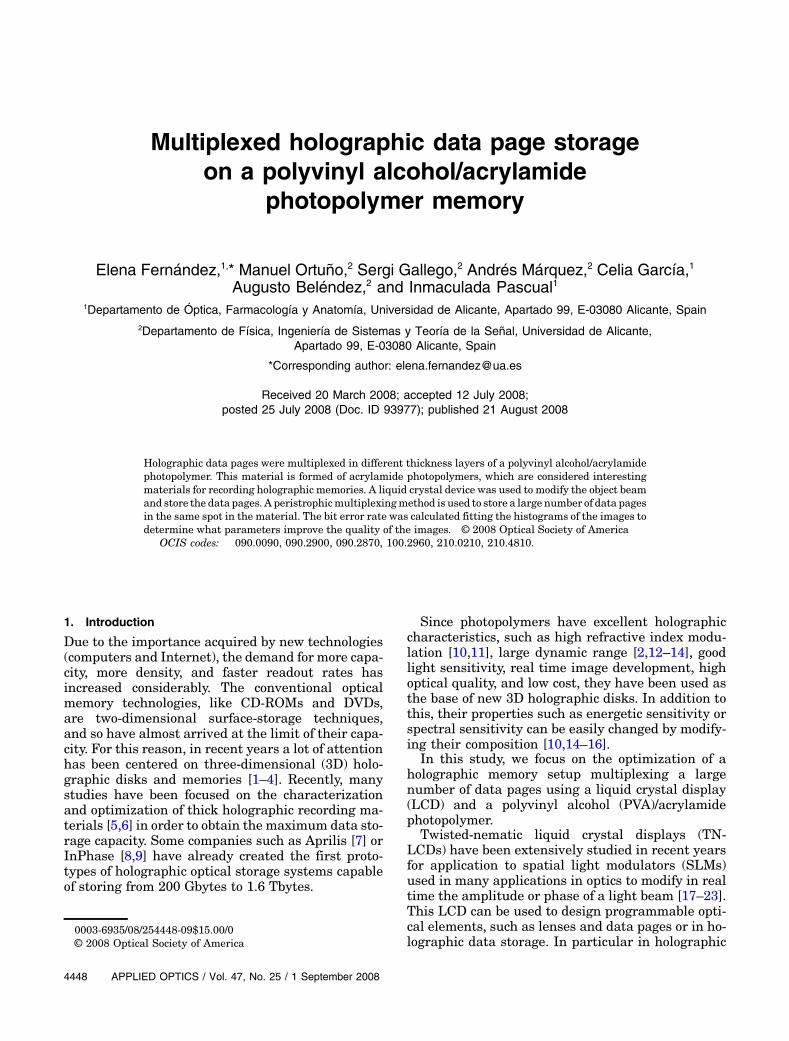
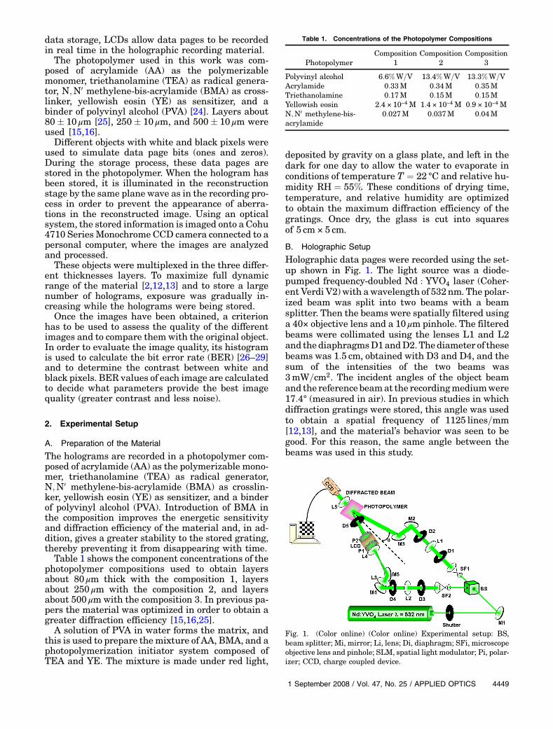
Holographic data pages were recorded using the set-up shown in Fig. 1. The light source was a diode-pumped frequency-doubled Nd : YVO4 laser (Coher-ent Verdi V2) with awavelength of 532nm. The polar-ized beam was split into two beams with a beamsplitter. Then the beams were spatially filtered usinga 40× objective lens and a 10 μm pinhole. The filteredbeams were collimated using the lenses L1 and L2and the diaphragmsD1andD2.Thediameter of thesebeams was 1:5 cm, obtained with D3 and D4, and thesum of the intensities of the two beams was3mW=cm2. The incident angles of the object beamand the reference beamat the recordingmediumwere17:4° (measured in air). In previous studies in whichdiffraction gratings were stored, this angle was usedto obtain a spatial frequency of 1125 lines=mm[12,13], and the material’s behavior was seen to begood. For this reason, the same angle between thebeams was used in this study.
Table 1. Concentrations of the Photopolymer Compositions
PhotopolymerComposition
1Composition
2Composition
3
Polyvinyl alcohol 6:6%W=V 13:4%W=V 13:3%W=VAcrylamide 0:33M 0:34M 0:35MTriethanolamine 0:17M 0:15M 0:15MYellowish eosin 2:4 × 10⁻⁴ M 1:4 × 10⁻⁴ M 0:9 × 10⁻⁴ MN;N0 methylene-bis-acrylamide
0:027M 0:037M 0:04M
Fig. 1. (Color online) (Color online) Experimental setup: BS,beam splitter; Mi, mirror; Li, lens; Di, diaphragm; SFi, microscopeobjective lens and pinhole; SLM, spatial light modulator; Pi, polar-izer; CCD, charge coupled device.
1 September 2008 / Vol. 47, No. 25 / APPLIED OPTICS 4449
One of the beams was the object beam, and theother was the reference beam. The object beamwas directed onto the surface of a 800 × 600 TN-LCD with a pixel pitch of 32 μm. The LCD was placedbetween two polarizers, one to each side of the LCD.The set of LCD and polarizers was used as a SLM.The lens L3 (f 0 ¼ 200mm) was used to obtain a con-vergent beam, and the lenses L4 and L5 (f 0 ¼100mm) were placed to do the Fourier transform(FT) and the inverse Fourier transform (IFT) ofthe data pages. We used this scheme because we ob-tained a flexibility configuration: the size of the FTwas under control by moving the LCD along the axis.By increasing d, the size of the FT was made larger,and decreasing d, the size of the FT was made smal-ler. A diaphragm was placed just before the photopo-lymer to block all the orders that leave the LCDexcept the central order. If the other orders werenot blocked, they would also be stored in the materi-al, and during reconstruction, interference patternswould be observed on the image, thus worsening itsquality. The other beam, the reference beam, was aplane wave that interfered with the object beam atthe surface of the material. These beam intensitieswere measured at the position where the photopoly-mer must be placed when the holograms are stored.In the reconstruction stage, the stored hologram
that contained the information of the data pagewas illuminated with the reference beam, but at avery low intensity so as not to erase the hologram be-cause the material was sensitive at this wavelength.Another lens was placed behind the photopolymer todo the inverse Fourier transform (IFT) of the dif-fracted beam on the surface of the charge coupled de-vice (CCD). A computer sends the data pages to theLCD and captures images reconstructed by the CCD.In order to ensure the stability of the experimental
setup for long exposure times, a holographic tablewith an antivibration system was used.
3. Results and Discussion
In this paper, we want a large number of data pagesbe stored in a PVA/acrylamide photopolymer. For thisreason, holograms have been multiplexed for differ-ent thicknesses of the material, 80 μm, 250 μm, and500 μm, using the compositions in Table 1. In eachlayer, binary data pages with a random pixel formwere stored. These objects have a different numberof pixels: 300 × 300, 400 × 400, 500 × 500, and 800 ×600 pixels. This allows us to study the behavior of thephotopolymer material when data pages with differ-ent numbers of pixels are multiplexed.These objects were stored in the same position in
thematerial using peristrophic multiplexing becauseprevious papers showed that when a not very largenumber of holograms (fewer than 200 holograms)are to be stored, a higher diffraction efficiency is ob-tained with peristrophic multiplexing [13]. By chan-ging the thickness of the material, the number ofholograms that can be stored will also change. With
a greater thickness, the material will have a greaterdynamic rangeandmorehologramsmaybe stored [2].
The holograms were stored with an angular se-paration of 3°. The angular selectivity was measuredfor the different thicknesses used in this study. For athickness of 500 μm, we obtained an angular selectiv-ity of 1°, for 250 μm, 1:5°, and for 80 μm, 2°. Thereforean angular separation of 3° is more than sufficient toprevent the holograms from overlapping.
The holograms were stored with a reference to ob-ject beam ratio of 100 and a reading beam intensity of0:03mW=cm2. In a previous study on the influence ofthese parameters on the quality of the stored images[25], these values were found to give a greater imagequality and therefore a lower BER.
A. Optimization of the LCD
As described in the holographic setup section, anLCD(LCD2002 Holoeye SONY LCX016AL-6 800 × 600pixels) was placed in the object beam to modify thewavefront and store this variation in the photopoly-mer. The variation may be in phase or amplitude.In this study, the wavefront amplitude is modified,while its phase is maintained constant, and this mod-ification is the object to be stored in the photopolymer.The object has two states:white,withamaximumam-plitude transmittance, and black, with a minimumamplitude transmittance. The optimization processof the LCD can be seen in [17–23].
LCDs change the polarization state of the incidentlight. This may mean that not all the light incidenton the LCD is transmitted, since some of it is re-flected or absorbed. Therefore it is advisable to placetwo polarizers, one before and one after the LCD, inorder to transmit the maximum light possible. How-ever, to achieve this, the LCD and polarizers must becalibrated correctly, which means that the angles atwhich the latter are to be placed in order to achievemaximum efficiency and minimum loss must be cal-culated. In our study, the objective was also to obtainthe maximum contrast between transparent andopaque zones of the LCD with either no or minimalphase variation. Therefore before sending the objectsto the LCD for storage in the photopolymer, the LCDmust be correctly calibrated.
This is done using the method described in [19,20],which consists of two calibration steps. In the firststep, the LCD is turned off and no voltage is applied.In this step, three parameters that are independentof the voltage are calculated: the total twist angle (α),the orientation of the molecular director at the inputface (ψD), and themaximum birefringence (βmax). Theparameters obtained with the LCD calibrated whileturned off are shown in Table 2.
In the second step, the parameters dependent onvoltage are measured. These are related to the varia-tion in optical anisotropic properties throughout thethickness of the cell as a function of the voltage ap-plied. The model attempts to take into account thatthe liquid crystal molecules near the glass are practi-cally adhered to its surface and cannot reorientate
4450 APPLIED OPTICS / Vol. 47, No. 25 / 1 September 2008
themselves when the voltage is applied. Thus, thetotal thickness d of the LCDmay be decomposed intotwo lateral regions of width d1 and a central region ofwidth d2. In this way, the anisotropic properties of theLCD may be modeled using two voltage-dependentparameters, birefringence β and δ, which are ex-pressed in Eq. (1):
βðVÞ ¼ πΔnd2=λ0; δðVÞ ¼ πΔnmaxd1=λ0; ð1Þ
where λ0 is the wavelength of the light and Δn is thedifference between the ordinary and extraordinaryindices, with Δnmax being the maximum value.From the curves of βðVÞ and δðVÞ, we can find the
angles at which the polarizers must be placed in theexperimental setup to modulate the incident beam.In our study, our aim is to obtain the maximum con-trast between transparent and opaque zones of theLCD with minimum variation in the phase. In thiscase, the angles found are φ1 ¼ 296° for the polarizerin front of the LCD and φ2 ¼ 111° for the polarizerbehind it.
B. Calculation of the Bit Error Rate
After one of the objects has been stored in the photo-polymer, the hologram formed is reconstructed by il-luminating itwith the reference beam.Thediffractivebeam obtained is imaged onto the CCD. If the holo-graphic reconstruction were perfect, the images ob-tained would have uniform white and black pixels.However, many reasons exist thatmay distort the im-age (such as small imperfections in the material, par-ticles thatmaybe found inanyelement of the setup, orpoor contrast of the image obtained due to insufficientexposure). Since the images obtained are not perfectand exhibit noise, it is necessary to measure a para-meter that quantifies the image quality. This para-meter is the bit error rate (BER).The BER is defined as the probability of having er-
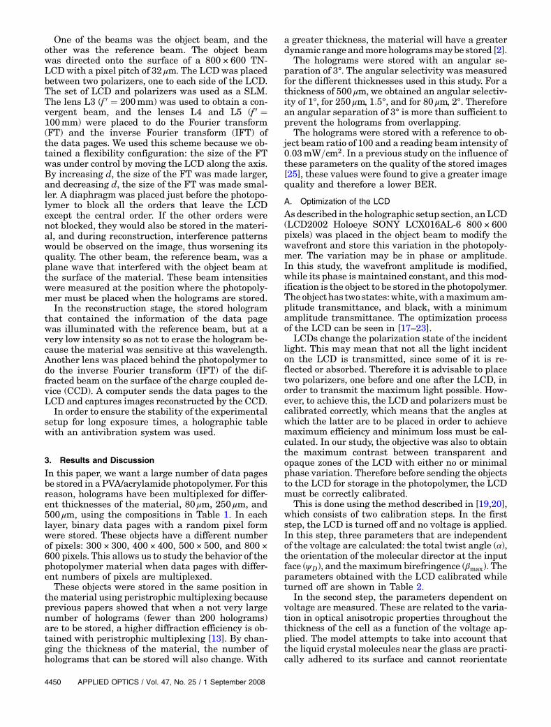
roneous bits in the image. To calculate the BER[25,26], first, in Fig. 2, we represent in logarithmicscale the probability of obtaining a certain gray levelin the black or the white regions. In Fig. 2, the prob-ability in the black regions is represented by solid cir-cles, and the probability in the white regions isrepresented by empty circles. As can be seen, thetwo probability distributions are clearly distinguish-able, although there is a point atwhich they intersect.This point of intersection of the two distributions iscalled xc.Once the probability distributions have been ob-
tained from the graph (Fig. 2), both distributionsare fitted to a probability function. In this study, theyare fitted to a Gaussian equation (Eq. (2)):
Wðx0; σ; xÞ ¼1ffiffiffiffiffiffiffiffi2πσ
p exp�−
ðx − x0Þ22σ2
�; ð2Þ
where x represents each gray level in the image, x0 isthe point at which the Gaussian distribution is cen-tered, and σ is the width of the Gaussian distribution.The reasonwhy they are fitted to aGaussian equationis that it has been verified that most probability dis-tributions obtained from an image captured by aCCDmay be expected to follow this type of distribution.
Once the adjustments for the probability distribu-tion of both white and black pixels have been made,the BER is calculated from Eq. (3):
BER ¼ 12
�Zxc
0WWðxÞdxþ
Z∞
xc
WBðxÞdx�; ð3Þ
where WW are WB are the adjustments of the prob-ability distribution of white and black pixels, respec-tively, and xc is the point of intersection of the twoprobability distributions.
Using this algorithm, the BERs of all the imagesare calculated and are discussed in the following sub-sections.
C. Thickness of 80 μmAsmentioned above, data pageswere storedwith fourdifferent pixel sizes. In this subsection, these fourdata pages are multiplexed in the 80 μm thick mate-rial. Each of the four objects is stored at the same po-sition in the material with an angular separation of3°. In addition, they are stored with a beam ratio of100 and reconstructed on the CCD with a readingbeam intensity of 0:03mW=cm2. In previous studiesit was found that when all the holograms were storedusing the same exposure time, the last hologramswere stored with lower diffraction efficiency or noteven formed. In order to increase the diffraction effi-ciency of the last holograms, it was found necessary toincrease the exposure of the holograms as they werebeing stored [12,13,30]. Therefore, since in this studythe objective is to store as many data pages as
Table 2. LCD Calibration Parameters Independent of the VoltageApplied
α ψD
βmaxðλ0 ¼ 633nmÞ
βmaxðλ0 ¼ 532nmÞ
βmaxðλ0 ¼ 442nmÞ
94°� 1° 45°� 1° 118°� 1° 168°� 1° 199°� 1°
Fig. 2. Distribution of the probability of black and white pixels.
1 September 2008 / Vol. 47, No. 25 / APPLIED OPTICS 4451
possible, the exposure is gradually increased as thedata pages are stored so that the last data pages havethe same BER as the first ones.In Fig. 3, the exposure time that the data pages
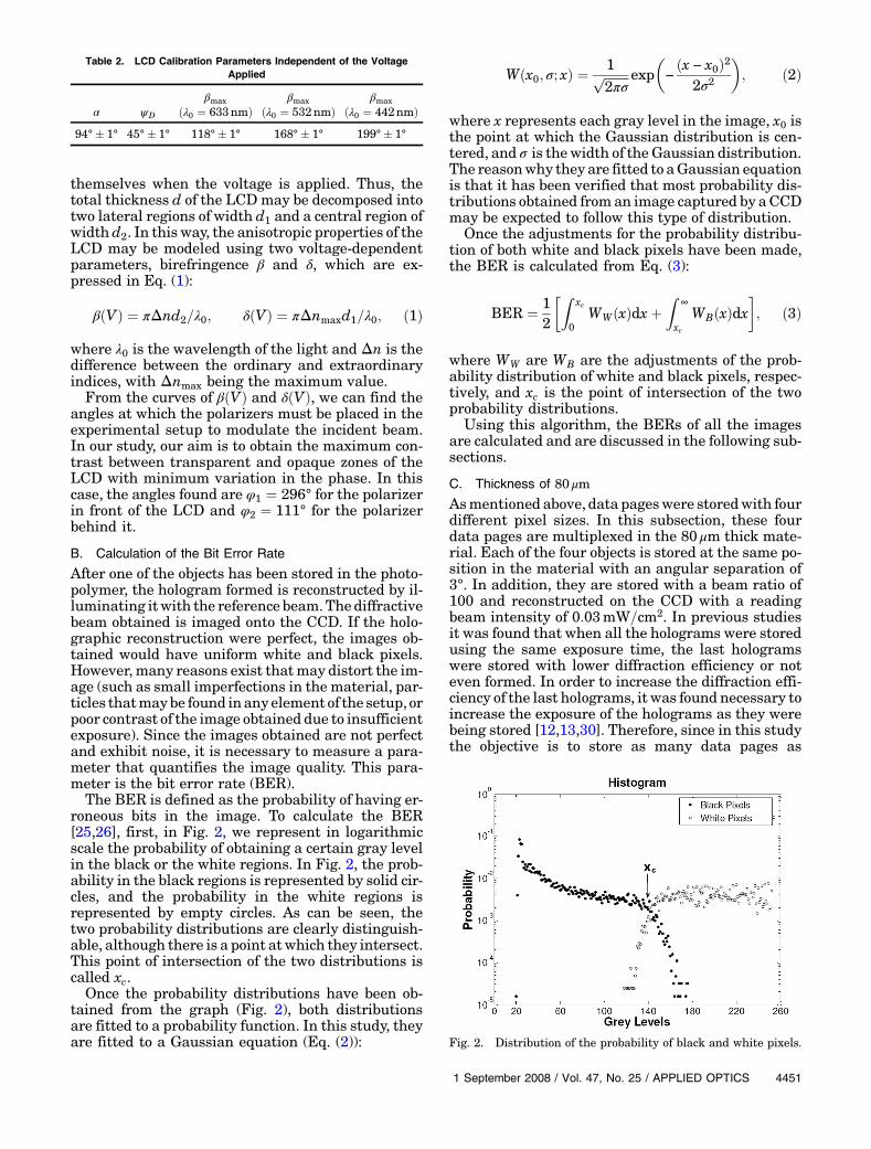
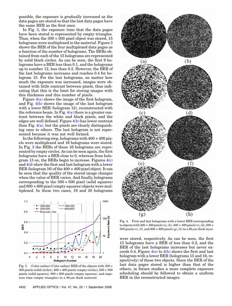
have been stored is represented by empty triangles.Thus, when the 300 × 300 pixel object was stored, 15hologramsweremultiplexed in thematerial. Figure 3shows the BER of the four multiplexed data pages asa function of the number of holograms. The BERs ob-tained from each of the 15 holograms are representedby solid black circles. As can be seen, the first 9 ho-lograms have a BER less than 0.1, and the hologramsup to number 12, less than 0.2. However, the BER ofthe last holograms increases and reaches 0.4 for ho-logram 15. For the last holograms, no matter howmuch the exposure was increased, images were ob-tained with little contrast between pixels, thus indi-cating that this is the limit for storing images withthis thickness and this number of pixels.Figure 4(a) shows the image of the first hologram,
and Fig. 4(b) shows the image of the last hologramwith a lower BER (hologram 12), reconstructed withthe reference beam. In Fig. 4(a) there is a greater con-trast between the white and black pixels, and theedges are well defined. Figure 4(b) has lower contrastthan Fig. 4(a), but the pixels are clearly distinguish-ing ones to others. The last hologram is not repre-sented because it was not well formed.In the following step, hologramswith 400 × 400pix-
els were multiplexed and 16 holograms were stored.In Fig. 3 the BERs of these 16 holograms are repre-sented by empty circles. As can be seen again, the firstholograms have a BER close to 0, whereas from holo-gram 13 on, the BERs begin to increase. Figures 4(c)and 4(d) show the first and last hologramwith a lowerBER (hologram16) of the 400 × 400pixel object. It canbe seen that the quality of the stored image changeswhen the value of BER varies. And finally, hologramscorresponding to the 500 × 500 pixel (solid squares)and800 × 600pixel (empty squares) objectsweremul-tiplexed. In these two cases, 19 and 20 holograms
were stored, respectively. As can be seen, the first15 holograms have a BER of less than 0.2, and theBER of the last holograms increases but never ex-ceeds 0.4. Figure 4(e) to 4(h) shows the first and lasthologramwith a lower BER (holograms 15 and 16, re-spectively) of these two objects. Since the BER of thelast data pages stored is higher than that of theothers, in future studies a more complete exposurescheduling should be followed to obtain a uniformBER in the reconstructed images.
Fig. 3. (Color online) (Color online) BER of the objects with 300 ×300 pixels (solid circles), 400 × 400 pixels (empty circles), 500 × 500pixels (solid squares), 800 × 800 pixels (empty squares), and expo-sure time (empty triangles) in a 80 μm thick material.
Fig. 4. First and last holograms with a lower BER correspondingtoobjectswith300 × 300pixels (a), (b),400 × 400pixels (c), (d),500 ×500 pixels (e), (f), and 800 × 600 pixels (g), (h) in a 80 μm thick layer.
4452 APPLIED OPTICS / Vol. 47, No. 25 / 1 September 2008
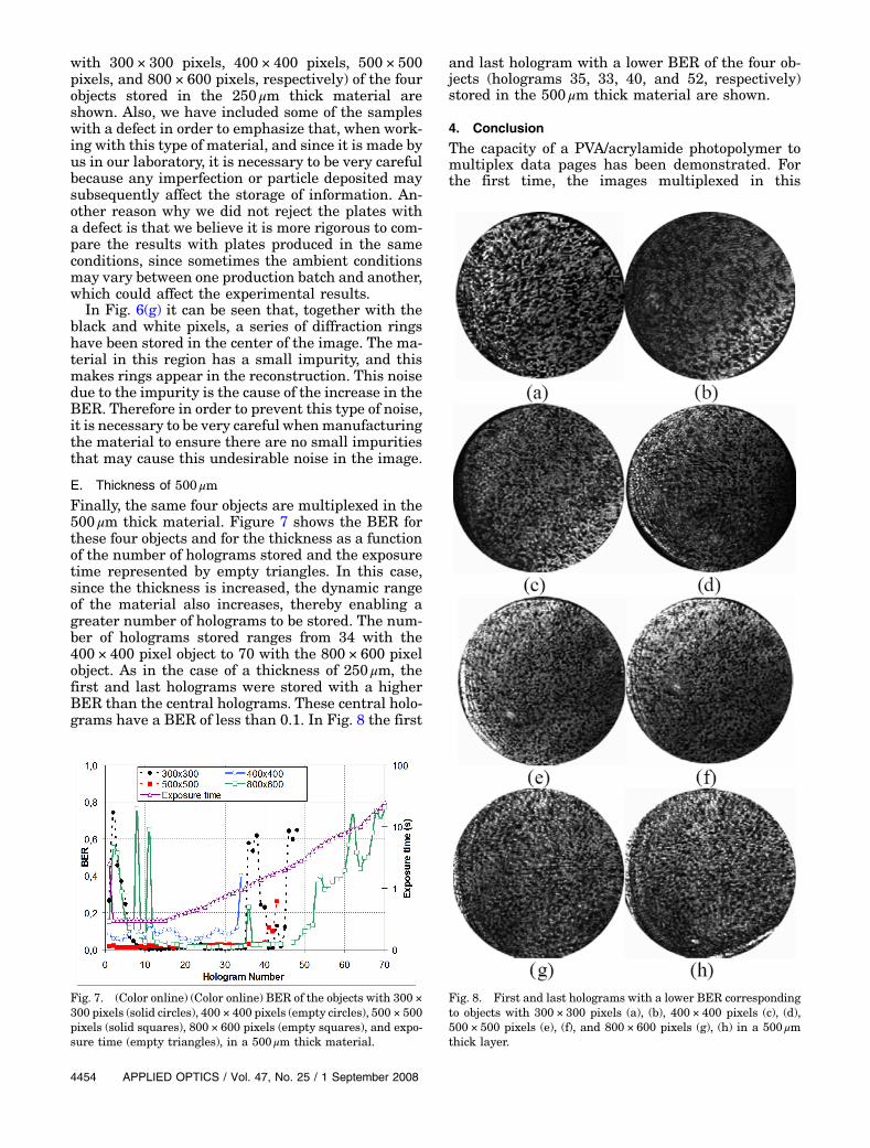
D. Thickness of 250 μmIn this subsection, the same objects as those in theprevious subsection are multiplexed, but now in a250 μm thick material. In Fig. 5 the BER for thesefour objects stored with this thickness is representedas a function of the number of holograms. The expo-sure time that the data pages have been stored is re-presented by empty triangles. The most importantchange between Fig. 3 and 5 is that in Fig. 5 moreholograms have been stored (up to 30 holograms)due to the increase in thickness of the photopolymerlayer used.With this thickness it can be seen that the first ho-
lograms (up to hologram 6, depending on the object)have a higher BER than those in the central region(holograms up to number 28 for the 800 × 600 pixelobject). It has been reported that holograms have ahigh BER due to the lack of exposure used when stor-ing them. This means that the holograms are notproperly formed, and the images obtained are notof good quality. Therefore in these first hologramsin which the storage limit has not been reached, hav-ing a BER of over 0.1means that the exposure used tostore them was not sufficient. Since the material isthicker, its energetic sensitivity is different, whichmakes it necessary to use a greater exposure for thesefirst holograms to be formed properly. However, theexposure with which the first two or three hologramsshould be stored is very critical when greater thick-nesses are used [12,13]. If the exposure is not suffi-cient, the hologram is not formed, whereas if theexposure is increased toomuch, a large part of the dy-namic range is consumed and fewer holograms maybe stored. For this reason, it is necessary to reach acompromise to obtain the best results. In this study,we opted for sacrificing the first holograms, whichmeant that they had a slightly higher BER thanthe central holograms (where the material behavesin a more linear way), in order to be able to store alarger number of holograms. The last hologramsagain have a high BER since the storage limit for this
thickness has been reached.With the exception of thefirst and last holograms, it can be seen that theBERofthe central holograms is constant and less than 0.1 forthe first three objects. However, for the 800 × 600 pix-el object, the mean BER of the first 25 holograms isgreater than that of the other objects.
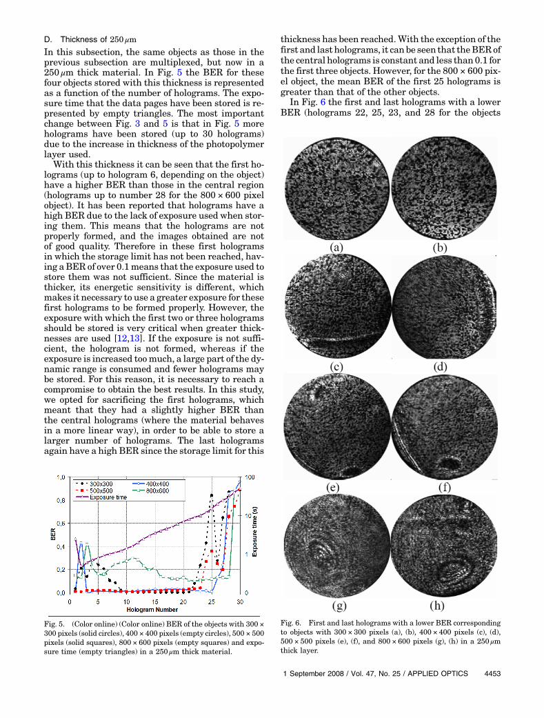
In Fig. 6 the first and last holograms with a lowerBER (holograms 22, 25, 23, and 28 for the objects
Fig. 5. (Color online) (Color online) BER of the objects with 300 ×300 pixels (solid circles), 400 × 400 pixels (empty circles), 500 × 500pixels (solid squares), 800 × 600 pixels (empty squares) and expo-sure time (empty triangles) in a 250 μm thick material.
Fig. 6. First and last holograms with a lower BER correspondingto objects with 300 × 300 pixels (a), (b), 400 × 400 pixels (c), (d),500 × 500 pixels (e), (f), and 800 × 600 pixels (g), (h) in a 250 μmthick layer.
1 September 2008 / Vol. 47, No. 25 / APPLIED OPTICS 4453
with 300 × 300 pixels, 400 × 400 pixels, 500 × 500pixels, and 800 × 600 pixels, respectively) of the fourobjects stored in the 250 μm thick material areshown. Also, we have included some of the sampleswith a defect in order to emphasize that, when work-ing with this type of material, and since it is made byus in our laboratory, it is necessary to be very carefulbecause any imperfection or particle deposited maysubsequently affect the storage of information. An-other reason why we did not reject the plates witha defect is that we believe it is more rigorous to com-pare the results with plates produced in the sameconditions, since sometimes the ambient conditionsmay vary between one production batch and another,which could affect the experimental results.In Fig. 6(g) it can be seen that, together with the
black and white pixels, a series of diffraction ringshave been stored in the center of the image. The ma-terial in this region has a small impurity, and thismakes rings appear in the reconstruction. This noisedue to the impurity is the cause of the increase in theBER. Therefore in order to prevent this type of noise,it is necessary to be very careful whenmanufacturingthe material to ensure there are no small impuritiesthat may cause this undesirable noise in the image.
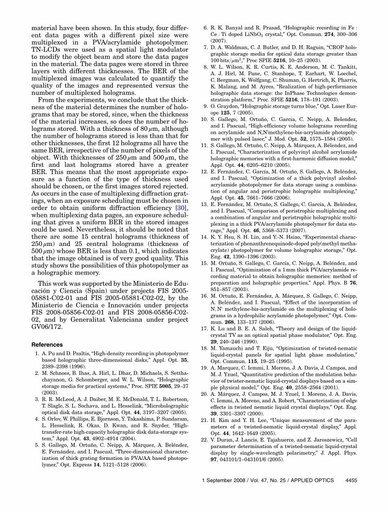
E. Thickness of 500 μmFinally, the same four objects are multiplexed in the500 μm thick material. Figure 7 shows the BER forthese four objects and for the thickness as a functionof the number of holograms stored and the exposuretime represented by empty triangles. In this case,since the thickness is increased, the dynamic rangeof the material also increases, thereby enabling agreater number of holograms to be stored. The num-ber of holograms stored ranges from 34 with the400 × 400 pixel object to 70 with the 800 × 600 pixelobject. As in the case of a thickness of 250 μm, thefirst and last holograms were stored with a higherBER than the central holograms. These central holo-grams have a BER of less than 0.1. In Fig. 8 the first
and last hologram with a lower BER of the four ob-jects (holograms 35, 33, 40, and 52, respectively)stored in the 500 μm thick material are shown.
4. Conclusion
The capacity of a PVA/acrylamide photopolymer tomultiplex data pages has been demonstrated. Forthe first time, the images multiplexed in this
Fig. 7. (Color online) (Color online) BER of the objects with 300 ×300 pixels (solid circles), 400 × 400 pixels (empty circles), 500 × 500pixels (solid squares), 800 × 600 pixels (empty squares), and expo-sure time (empty triangles), in a 500 μm thick material.
Fig. 8. First and last holograms with a lower BER correspondingto objects with 300 × 300 pixels (a), (b), 400 × 400 pixels (c), (d),500 × 500 pixels (e), (f), and 800 × 600 pixels (g), (h) in a 500 μmthick layer.
4454 APPLIED OPTICS / Vol. 47, No. 25 / 1 September 2008
material have been shown. In this study, four differ-ent data pages with a different pixel size weremultiplexed in a PVA/acrylamide photopolymer.TN-LCDs were used as a spatial light modulatorto modify the object beam and store the data pagesin the material. The data pages were stored in threelayers with different thicknesses. The BER of themultiplexed images was calculated to quantify thequality of the images and represented versus thenumber of multiplexed holograms.From the experiments, we conclude that the thick-
ness of the material determines the number of holo-grams that may be stored, since, when the thicknessof the material increases, so does the number of ho-lograms stored. With a thickness of 80 μm, althoughthe number of holograms stored is less than that forother thicknesses, the first 12 holograms all have thesame BER, irrespective of the number of pixels of theobject. With thicknesses of 250 μm and 500 μm, thefirst and last holograms stored have a greaterBER. This means that the most appropriate expo-sure as a function of the type of thickness usedshould be chosen, or the first images stored rejected.As occurs in the case of multiplexing diffraction grat-ings, when an exposure scheduling must be chosen inorder to obtain uniform diffraction efficiency [30],when multiplexing data pages, an exposure schedul-ing that gives a uniform BER in the stored imagescould be used. Nevertheless, it should be noted thatthere are some 15 central holograms (thickness of250 μm) and 25 central holograms (thickness of500 μm) whose BER is less than 0.1, which indicatesthat the image obtained is of very good quality. Thisstudy shows the possibilities of this photopolymer asa holographic memory.
This work was supported by theMinisterio de Edu-cación y Ciencia (Spain) under projects FIS 2005-05881-C02-01 and FIS 2005-05881-C02-02, by theMinisterio de Ciencia e Innovación under projectsFIS 2008-05856-C02-01 and FIS 2008-05856-C02-02, and by Generalitat Valenciana under projectGV06/172.
References1. A. Pu and D. Psaltis, “High-density recording in photopolymer
based holographic three-dimensional disks,” Appl. Opt. 35,2389–2398 (1996).
2. M. Schnoes, B. Ihas, A. Hirl, L. Dhar, D. Michaels, S. Settha-chayanon, G. Schomberger, and W. L. Wilson, “Holographicstorage media for practical systems,” Proc. SPIE 5005, 29–37(2003).
3. R. R. McLeod, A. J. Daiber, M. E. McDonald, T. L. Robertson,T. Slagle, S. L. Sochava, and L. Hesselink, “Microholographicoptical disk data storage,” Appl. Opt. 44, 3197–3207 (2005).
4. S. Orlov, W. Phillips, E. Bjornson, Y. Takashima, P. Sundaram,L. Hesselink, R. Okas, D. Kwan, and R. Snyder, “High-transfer-rate high-capacity holographic disk data-storage sys-tem,” Appl. Opt. 43, 4902–4914 (2004).
5. S. Gallego, M. Ortuño, C. Neipp, A. Márquez, A. Beléndez,E. Fernández, and I. Pascual, “Three-dimensional character-ization of thick grating formation in PVA/AA based photopo-lymer,” Opt. Express 14, 5121–5128 (2006).
6. R. K. Banyal and R. Prasad, “Holographic recording in Fe :
Ce : Ti doped LiNbO3 crystal,” Opt. Commun. 274, 300–306(2007).
7. D. A. Waldman, C. J. Butler, and D. H. Raguin, “CROP holo-graphic storage media for optical data storage greater than100bits=μm2,” Proc SPIE 5216, 10–25 (2003).
8. W. L. Wilson, K. R. Curtis, K. E. Anderson, M. C. Tankitt,A. J. Hirl, M. Pane, C. Stanhope, T. Earhart, W. Loechel,C. Bergman, K. Wolfgang, C. Shuman, G. Hertrich, K. Pharris,K. Malang, and M. Ayres, “Realization of high-performanceholographic data storage: the InPhase Technologies demon-stration platform,” Proc. SPIE 5216, 178–191 (2003).
9. O. Graydon, “Holographic storage turns blue,”Opt. Laser Eur-ope 125, 7 (2005).
10. S. Gallego, M. Ortuño, C. Garcia, C. Neipp, A. Belendez,and I. Pascual, “High-efficiency volume holograms recordingon acrylamide and N,N’methylene-bis-acrylamide photopoly-mer with pulsed laser,” J. Mod. Opt. 52, 1575–1584 (2005).
11. S. Gallego, M. Ortuño, C. Neipp, A. Márquez, A. Bélendez, andI. Pascual, “Characterization of polyvinyl alcohol acrylamideholographic memories with a first-harmonic diffusion model,”Appl. Opt. 44, 6205–6210 (2005).
12. E. Fernández, C. García, M. Ortuño, S. Gallego, A. Beléndez,and I. Pascual, “Optimization of a thick polyvinyl alcohol-acrylamide photopolymer for data storage using a combina-tion of angular and peristrophic holographic multiplexing,”Appl. Opt. 45, 7661–7666 (2006).
13. E. Fernández, M. Ortuño, S. Gallego, C. García, A. Beléndez,and I. Pascual, “Comparison of peristrophic multiplexing anda combination of angular and peristrophic holographic multi-plexing in a thick PVA/acrylamide photopolymer for data sto-rage,” Appl. Opt. 46, 5368–5373 (2007).
14. K. Y. Hsu, S. H. Lin, and Y.-N. Hsiao, “Experimental charac-terization of phenanthrenequinode-doped poly(methyl metha-crylate) photopolymer for volume holographic storage,” Opt.Eng. 42, 1390–1396 (2003).
15. M. Ortuño, S. Gallego, C. García, C. Neipp, A. Beléndez, andI. Pascual, “Optimization of a 1mm thick PVA/acrylamide re-cording material to obtain holographic memories: method ofpreparation and holographic properties,” Appl. Phys. B 76,851–857 (2003).
16. M. Ortuño, E. Fernández, A. Márquez, S. Gallego, C. Neipp,A. Beléndez, and I. Pascual, “Effect of the incorporation ofN;N0 methylene-bis-acrylamide on the multiplexing of holo-grams in a hydrophilic acrylamide photopolymer,” Opt. Com-mun. 268, 133–137 (2006).
17. K. Lu and B. E. A. Saleh, “Theory and design of the liquid-crystal TV as an optical spatial phase modulator,” Opt. Eng.29, 240–246 (1990).
18. M. Yamauchi and T. Eiju, “Optimization of twisted-nematicliquid-crystal panels for spatial light phase modulation,”Opt. Commun. 115, 19–25 (1995).
19. A. Marquez, C. Iemmi, I. Moreno, J. A. Davis, J. Campos, andM. J. Yzuel, “Quantitative prediction of the modulation beha-vior of twister-nematic liquid-crystal displays based on a sim-ple physical model,” Opt. Eng. 40, 2558–2564 (2001).
20. A. Márquez, J. Campos, M. J. Yzuel, I. Moreno, J. A. Davis,C. Iemmi, A. Moreno, and A. Robert, “Characterization of edgeeffects in twisted nematic liquid crystal displays,” Opt. Eng.39, 3301–3307 (2000).
21. H. Kim and Y. H. Lee, “Unique measurement of the para-meters of a twisted-nematic liquid-crystal display,” Appl.Opt. 44, 1642–1649 (2005).
22. V. Duran, J. Lancis, E. Tajahuerce, and Z. Jaroszewicz, “Cellparameter determination of a twisted-nematic liquid-crystaldisplay by single-wavelength polarimetry,” J. Appl. Phys.97, 043101/1–043101/6 (2005).
1 September 2008 / Vol. 47, No. 25 / APPLIED OPTICS 4455
23. J. Jang and D. Shin, “Optical representation of binary databased on both intensity and phase modulation with atwisted-nematic liquid-crystal display for holographic digitaldata storage,” Opt. Lett. 26, 1797–1799 (2001).
24. M. R. Gleeson, J. V. Kelly, C. E. Close, F. T. O’Neill, andJ. T. Sheridan, “Effects of absorption and inhibition duringgrating formation in photopolymer materials,” J. Opt. Soc.Am. B 23, 2079–2088 (2006).
25. E. Fernández, M. Ortuño, A.Márquez, S. Gallego, A. Beléndez,and I. Pascual, “Optimization of a holographic memory usingan LCD and a PVA based photopolymer,” Proc. SPIE 6587,65870J/1–65870J/9 (2007).
26. H. J. Coufal, D. Psaltis, and G. T. Sincerbox,Holographic DataStorage (Springer-Verlag, 2000).
27. L. Dhar, K. Curtis, M. Tackitt, M. Schilling, S. Campbell,W. Wilson, A. Hill, C. Boyd, N. Levinos, and A. Harris,“Holographic storage of multiple high-capacity digital datapages in thick photopolymer systems,” Opt. Lett. 23, 1710–1712 (1998).
28. M. Keskinoz and B. V. K. Vijaya Kumar, “Application of linearminimum mean-squared-error equalization for volume holo-graphic data storage,” Appl. Opt. 38, 4387–4393 (1999).
29. P. Varhegyi, P. Koppa, F. Ujhelyi, and Lorincz, “System mod-eling and optimization of Fourier holographic memory,” Appl.Opt. 44, 3024–3031 (2005).
30. A. Pu, K. Curtis, and D. Psaltis, “Exposure schedule for multi-plexing holograms in photopolymer films,” Opt. Eng. 35,2824–2829 (1996).
4456 APPLIED OPTICS / Vol. 47, No. 25 / 1 September 2008