Embed Size (px)
Citation preview
M u l t i p l e x D r i l l i n g C o n t r o l S y s t e m s
Electronics Overview
Surface EquipmentEach of the two system control panels, the driller’s paneland the auxiliary (toolpusher’s) panel, is capable of full,independent, control of the subsea drilling system. Allcommands and status changes are transmitted to all electrohydraulic control units over redundant data high-ways. All status changes are received by each multiplexcontrol unit to ensure that they are all continuously updatedand have identical data. The use of redundant controllersand data highways ensures that full subsea BOP control isavailable even if either of the control panels or data highways is inoperable.
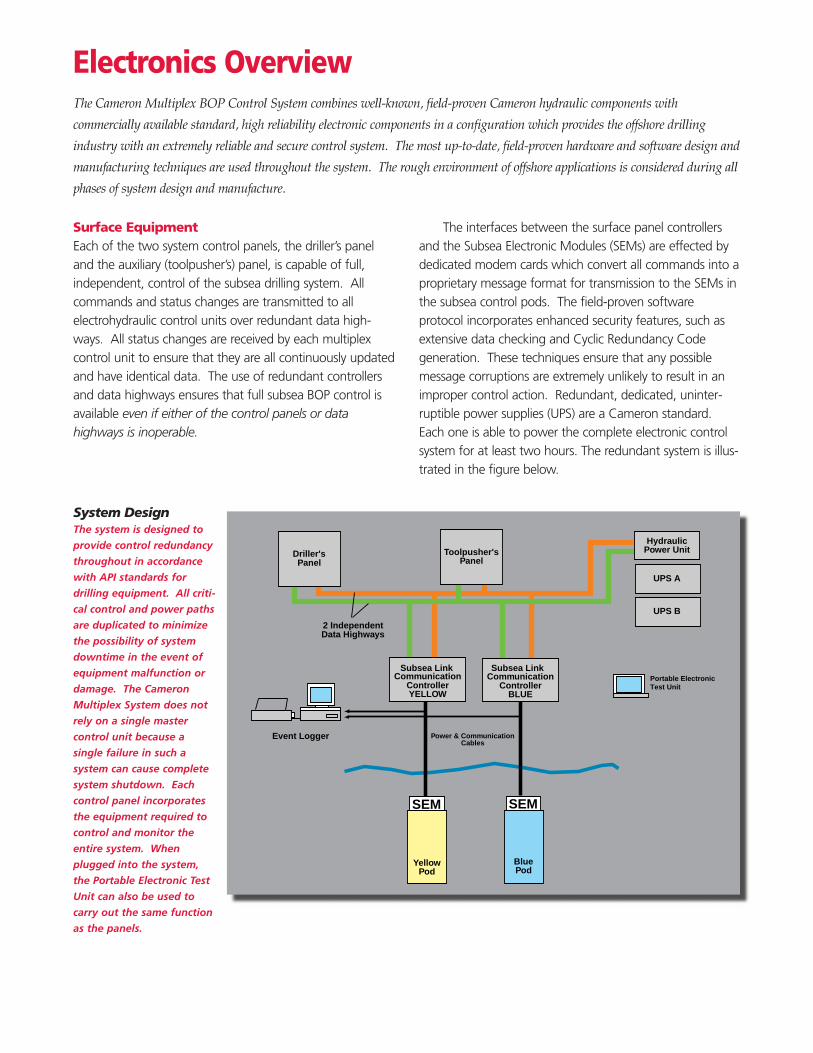
The interfaces between the surface panel controllersand the Subsea Electronic Modules (SEMs) are effected bydedicated modem cards which convert all commands into aproprietary message format for transmission to the SEMs inthe subsea control pods. The field-proven software protocol incorporates enhanced security features, such asextensive data checking and Cyclic Redundancy Code generation. These techniques ensure that any possiblemessage corruptions are extremely unlikely to result in animproper control action. Redundant, dedicated, uninter-ruptible power supplies (UPS) are a Cameron standard.Each one is able to power the complete electronic controlsystem for at least two hours. The redundant system is illus-trated in the figure below.
Event Logger
SEM SEM
2 IndependentData Highways
Power & CommunicationCables
YellowPod
BluePod
UPS A
HydraulicPower UnitToolpusher's
Panel
CommunicationControllerYELLOW
CommunicationSubsea Link Subsea Link
ControllerBLUE
UPS B
Driller'sPanel
Portable ElectronicTest Unit
The Cameron Multiplex BOP Control System combines well-known, field-proven Cameron hydraulic components with
commercially available standard, high reliability electronic components in a configuration which provides the offshore drilling
industry with an extremely reliable and secure control system. The most up-to-date, field-proven hardware and software design and
manufacturing techniques are used throughout the system. The rough environment of offshore applications is considered during all
phases of system design and manufacture.
System DesignThe system is designed to
provide control redundancy
throughout in accordance
with API standards for
drilling equipment. All criti-
cal control and power paths
are duplicated to minimize
the possibility of system
downtime in the event of
equipment malfunction or
damage. The Cameron
Multiplex System does not
rely on a single master
control unit because a
single failure in such a
system can cause complete
system shutdown. Each
control panel incorporates
the equipment required to
control and monitor the
entire system. When
plugged into the system,
the Portable Electronic Test
Unit can also be used to
carry out the same function
as the panels.
Electronics Overview
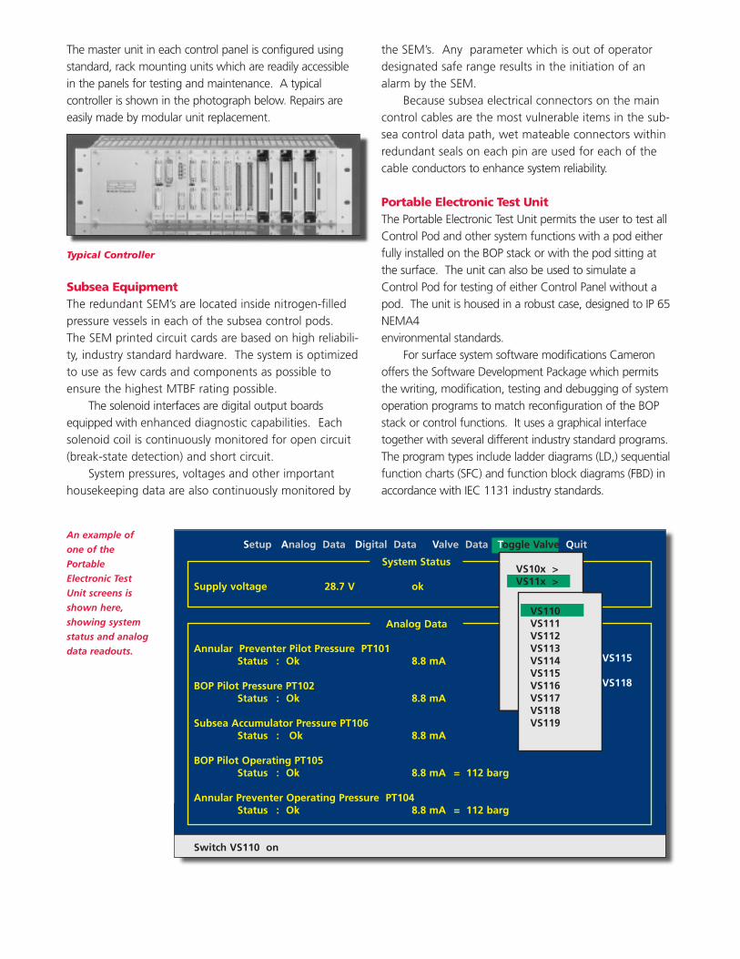
The master unit in each control panel is configured usingstandard, rack mounting units which are readily accessiblein the panels for testing and maintenance. A typical controller is shown in the photograph below. Repairs areeasily made by modular unit replacement.
Subsea EquipmentThe redundant SEM’s are located inside nitrogen-filledpressure vessels in each of the subsea control pods.The SEM printed circuit cards are based on high reliabili-ty, industry standard hardware. The system is optimizedto use as few cards and components as possible toensure the highest MTBF rating possible.
The solenoid interfaces are digital output boardsequipped with enhanced diagnostic capabilities. Eachsolenoid coil is continuously monitored for open circuit(break-state detection) and short circuit.
System pressures, voltages and other importanthousekeeping data are also continuously monitored by
the SEM’s. Any parameter which is out of operatordesignated safe range results in the initiation of analarm by the SEM.
Because subsea electrical connectors on the maincontrol cables are the most vulnerable items in the sub-sea control data path, wet mateable connectors withinredundant seals on each pin are used for each of thecable conductors to enhance system reliability.
Portable Electronic Test UnitThe Portable Electronic Test Unit permits the user to test allControl Pod and other system functions with a pod eitherfully installed on the BOP stack or with the pod sitting atthe surface. The unit can also be used to simulate aControl Pod for testing of either Control Panel without apod. The unit is housed in a robust case, designed to IP 65NEMA4 environmental standards.
For surface system software modifications Cameronoffers the Software Development Package which permitsthe writing, modification, testing and debugging of systemoperation programs to match reconfiguration of the BOPstack or control functions. It uses a graphical interfacetogether with several different industry standard programs.The program types include ladder diagrams (LD,) sequentialfunction charts (SFC) and function block diagrams (FBD) inaccordance with IEC 1131 industry standards.
VS110VS111VS112VS113VS114VS115VS116VS117VS118VS119
VS110VS111VS112VS113VS114VS115VS116VS117VS118VS119
VS10x >
Analog Data
Typical Controller
An example of
one of the
Portable
Electronic Test
Unit screens is
shown here,
showing system
status and analog
data readouts.
Supply voltage 28.7 V ok
Annular Preventer Pilot Pressure PT101Status : Ok 8.8 mA
BOP Pilot Pressure PT102Status : Ok 8.8 mA
Subsea Accumulator Pressure PT106Status : Ok 8.8 mA
BOP Pilot Operating PT105 Status : Ok 8.8 mA = 112 barg
Annular Preventer Operating Pressure PT104Status : Ok 8.8 mA = 112 barg
Switch VS110 on
Setup Analog Data Digital Data Valve Data Toggle Valve Quit
VS110VS111VS112VS113VS114 VS115VS116VS117 VS118VS119
VS110VS111VS112VS113VS114VS115VS116VS117VS118VS119
VS10x >VS11x >
System Status
Analog Data
Optional EquipmentCameron strongly recommends the use of an optionalEvent Logger along with the MUX system. The EventLogger is used to create a permanent log of all impor-tant system events and status changes. It may be con-nected either to the redundant BUS system or to thecommunication links down to the SEMs.
Technical SpecificationsAll boards in the surface controllers use the well known,standard VME interface and may be mixed with otherVME compatible cards from different suppliers. Theboards all mount in a 19” rack enclosure. Numerouscards are available to provide a wide range of processorsand processor speeds.
The following features are common for all boards:• Temperature range, industrial E2 (-40 °C to +80 °C)
or better• Shock and vibration tested according to IEC 68-2• EMV protection according to IEC 801 / VDE 0871• ESD protection according to IEC 801-2• MTBF in excess pf 14.3 years for the dual processor
configuration. MTBF figures for other configura-tions are available.
• Equipment in accordance with EN 50014...50020 (IEC 79-0, 2...11)
• Special ruggedized design• Optional conformal coating available• Supplier meets ISO 9001
A comprehensive component user list including offshore,space and military applications is available on request.
© Cooper Cameron Corporation, Cameron Division, Printed In USA, 3/97, 1CHC, WR6082/TC1146
Cameron P O Box 1212 • Houston, Texas 77251 1212 • Phone 713 683 4600 • Fax 713 683 4306 • http://www.camerondiv.com
Cameron GmbH Lueckenweg 1 • 29227 Celle Germany • Phone 011 49 5141 8060 • Fax 011 49 5141 806333