Embed Size (px)
Citation preview

Ductile Iron News Home Page
file:///C|/WEBSHARE/062013/magazine/2000_2/index.htm[6/19/2013 8:14:31 AM]
To Promote the production and application of ductile iron castings Issue 2, 2000
Multiple Channel Ultrasonic Instrument for Inspection Systems FEATURES
•Cover StoryMultiple Channel Ultrasonic Instrumenfor Inspection Systems
• Production and Machining of DuctileCast Iron
• Successful Automated Pouring ofDuctile Iron: Design and Operation
• Millis Scholarship Fund StudentsStudying Ductile Iron
•On the Suitability of ADI as anAlternative Material for (Railcar)Wheels
• Globe Metallurgical Names 2000Challenge Scholarship Winners
DEPARTMENTS
• News Briefs
• Foundry Member Profile - FarrarCorporation
• Associate Member Profile - HunterAutomated Machinery Corp.
• Associate Member Profile - Climax Research Services
•••

Ultrasonic Testing
file:///C|/WEBSHARE/062013/magazine/2000_2/inspection.htm[6/19/2013 8:14:31 AM]
Multiple Channel Ultrasonic Instrument for Inspection Systems
Ultrasonic testing is a common method of nondestructive testing used in manyindustries including foundries. Ultrasonic testing consists of transmitting soundthrough the part and making measurements to determine internal flaws, thicknessand nodularity.
Ultrasonic testing has the ability to:
Test an entire part without damaging it.
Allow inspection of every part versus destructive sampling methods.
The common tests and methods of nondestructive testing are:
Surface Examinations
1. Visual:
Detection of material and manufacturing defects before, during andafter each process by visually comparing, marking and measuring tospecification.
2. Magnetic Particle:
Detection of surface and near surface flaws on the ferromagnetic material (iron, steel, nickel).
The part is magnetized and magnetic particles are applied to the surface.
Flaw location indicated by particle patterns.
3. Liquid Penetrant:
Detection of discontinuities open to the part surface.
Penetrating liquid/dye applied to part surface.
Penetrates into and indicates location of flaw.
4. Eddy Current:
Eddy Currents are used for detection of surface and near surface flaws, changes in conductivity anddimensional changes.
Used in thin and small diameter electrically conductive parts.
Volumetric Examinations
1. Radiography:
Use of radiation (X-ray and Gamma ray) to penetrate a part and the flaw location is recorded on film
Detects flaws which (X-ray and Gammy ray) to penetrate a part and the flaw location is recorded on film
Not as effective in the detection of planar type flaws (such as delamintations)
2. Ultrasonics:
Detects flaws which present a reflective surface perpendicular to the sound beam
Ultrasonic Testing is Very Versatile

Ultrasonic Testing
file:///C|/WEBSHARE/062013/magazine/2000_2/inspection.htm[6/19/2013 8:14:31 AM]
Ultrasonic inspection is commonly used to satisfy many needs:
A wide variety of materials can be inspected; metals, plastics, composites
A broad range of applications including:
Ø Every inch of weld in pipe manufacturing
Ø Airplane turbine disks are inspected up to 5 times
Ø Spot-weld testing in the automotive industry
Ø Corrosion monitoring of tank walls
Ø Inspection of railroad wheels and rail
Ø Inspection of nuclear heat exchanger tubing.
Ø Plate testing for lamination and thickness
Ø Nodularity testing of safety related components for the automotive industry.
The types of testing that can be accomplished with Ultrasonics are:
Thickness Testing:
Sound travels into the part and returns after a measurable period of time.
Flaw Detection:
Sound travels into the part, reflecting from the defect
Flaw Sizing:
Reflector size is determined by signal amplitude
Velocity Testing:
Sound travels through the part at different speeds based on material properties.
The major advantages of ultrasonic testing:
Non-destructive
Access to the part may be from only one side
Safer than radiography
Ultrasonic Methods:
Pulse Echo Method
Through Transmission Method
Resonance Method
Ultrasonic Testing
file:///C|/WEBSHARE/062013/magazine/2000_2/inspection.htm[6/19/2013 8:14:31 AM]
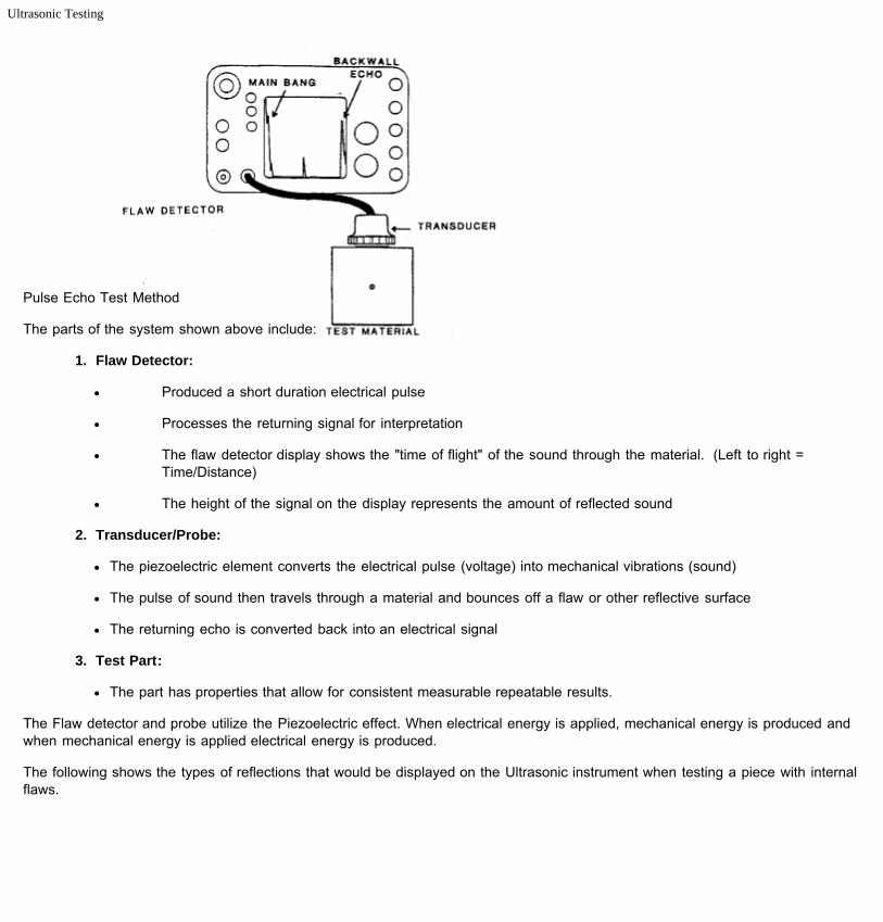
Pulse Echo Test Method
The parts of the system shown above include:
1. Flaw Detector:
Produced a short duration electrical pulse
Processes the returning signal for interpretation
The flaw detector display shows the "time of flight" of the sound through the material. (Left to right =Time/Distance)
The height of the signal on the display represents the amount of reflected sound
2. Transducer/Probe:
The piezoelectric element converts the electrical pulse (voltage) into mechanical vibrations (sound)
The pulse of sound then travels through a material and bounces off a flaw or other reflective surface
The returning echo is converted back into an electrical signal
3. Test Part:
The part has properties that allow for consistent measurable repeatable results.
The Flaw detector and probe utilize the Piezoelectric effect. When electrical energy is applied, mechanical energy is produced andwhen mechanical energy is applied electrical energy is produced.
The following shows the types of reflections that would be displayed on the Ultrasonic instrument when testing a piece with internalflaws.

Ultrasonic Testing
file:///C|/WEBSHARE/062013/magazine/2000_2/inspection.htm[6/19/2013 8:14:31 AM]
Nodularity testing consists of measuring the velocity of sound through a cast part and relating the sound speed to the nodularity.Ultrasonic sound velocity varies in different materials and each material has a measurable velocity. The following are the velocity ofsome common materials:
Mild Steel = 2.3 inches / sec 10e-5 (MS) Microseconds
Water = 0.584 inches / sec 10 e-5
Gold = 1.3 inches / sec 10 e-5
Lead = 0.87 inches / sec 10 e-5
Iron = 2.3 inches / sec 10 e-5
Iron (Cast) = 1.8 inches / sec 10 e-5
For cast irons, the velocity is not constant, but varies according to the degree or spherodisation of the total graphitecontent. It is this phenomena which we use to measure and check castings.

Ultrasonic Testing
file:///C|/WEBSHARE/062013/magazine/2000_2/inspection.htm[6/19/2013 8:14:31 AM]
Highly critical safety related automotive parts mandate ultrasonic testing:
· Ford, Nissan, Toyota, and Volkswagen specify an ultrasonic test for their safety related components.
The ultrasonic method is accepted for many test requirements and when the test is put on the production line 100% of the partsare inspected without having scrap with destructive testing. The typical cycle for in line inspection is as follows:
The operator or the robot loads the part into the immersion tank.
The immersion tank has a custom fixture for accurately holding the part between the transducers.
The operator removes his hands from the tank and then the test begins.
The part is tested.
An air stamper marks that part if it has passed the test.
The part is removed or automatically ejected into a good or bad bin.
The system tests both the velocity and the thickness of the part and additional channels can be added to test for flaws. Additionalchannels do not add to the cycle time and the typical time for a manually loaded system is 3 seconds total cycle time.
This type of system is manufactured by Krautkramer Branson utilizing the USPC-2100 computerized velocity testing machine.
· The USPC2100 has specific software to make the task simpler
Ø Part counter
Ø SPC
Ø Strip chart
Ø Data Logging
· Measurements can also be taken with hand held equipment
Ø DMV DL
The advances in computer technology have also advanced the ultrasonic testing method. Ultrasonic boards are available thatconvert a standard pentium computer into an ultrasonic instrument. This technology has created a much easier platform for testingallowing:
1. Easy integration in the foundry floor.
2. Programmable outputs and inputs to configure with robotic controls and PLC.
3. Windows-based operator interfaces that are easy to learn and run.
4. Less downtime and less expensive spare parts inventories.
5. Data logging for recording of results.
6. Networking for remote access.
The end result is that Ultrasonic testing can enhance your business by:
Increased business through the automotive industry
Fewer scraps by monitoring the process much closer
Ductile Home • Officers & Directors • Back Issues • Contact Us • Legal

Production and Machining of Ductile Cast Iron
file:///C|/WEBSHARE/062013/magazine/2000_2/abstract.htm[6/19/2013 8:14:28 AM]
Production and Machining of Ductile Cast Iron
Charles E. Bates, University of Alabama at BirminghamAbstract from the DIS June, 2000 Meeting
EXECUTIVE SUMMARY
There is a growing demand in machining centers for consistent ductile iron castings that have a consistent machinability. Higherspeeds increase throughput and minimize the capital and labor costs per part. However, machining at higher speeds requires partswith uniform microstructures, consistent properties, and a minimum volume fraction of abrasive inclusions.
Foundries that produce machinable castings occasionally encounter batches that are "hard-to-machine" or cause rapid tool wear. When this occurs, there may be a loss of tolerances and surface quality, a loss in productivity, machine down time, and higherscrap rates. Sometimes the only way to keep a machining center operating is to significantly reduce the cutting speed.
The Thin Wall Iron Casting Production and Machining project was started at the University of Alabama at Birmingham in 1995. The goals of the program were to (1) develop benchmark data on the machinability of ductile iron, (2) compare benchmark datawith data obtained from a variety of commercial castings, (3) define inclusions and other conditions that degrade machinability, (4)evaluate inoculants for their effectiveness in improving machinability, and (5) demonstrate approaches for mitigating factors thatdegrade machinability. The general approach to the program consisted of correlating the machinability of non-commercial castingsproduced in participating foundries with the production conditions and casting compositions to build a data base. Microstructureswere examined and correlated with machining characteristics of each iron.
Tool life curves were developed using carefully produced and well-characterized High Speed Steel (HSS) drills. "Acceptable" and"hard-to-machine" castings were also obtained from participating companies to determine differences in microstructure andcomposition that might explain reported differences in machinability. The results obtained on 'hard-to-machine" castings werecompared to results obtained in laboratory machining experiments.
Many factors can influence the machinability of iron. One of the purposes of this study was to identify and rank by severity thephases and conditions that have undesirable effects. Some of the factors that influence machinability include macro-inclusions,microcarbides, graphite distribution, strength, carbides and carbo-nitrides, and, to a lesser extent, the cleaning practices used onthe casting.
An advancing tool must shear the metal microstructure to produce the desired cut, but in doing so, it encounters a variety ofoxides, carbides, nitrides, sand, and other phases that may be present in the iron. These particles may be abrasive and acceleratetool wear.
Several phases can be present in iron, and their volume fraction and distribution are thought to have significant effects on tool life. Some of the phases that degrade machinability include (1) iron oxides and silicates formed during pouring; (2) carbides and ternaryiron phosphides formed during eutectic solidification; (3) titanium, vanadium, and niobium carbides, nitrides, and carbonitridesformed by reactions in the iron; and (4) chromium and molybdenum carbides formed during cooling of the casting.
Finely distributed carbides that form during solidification of cast iron have a detrimental effect on machinability. Carbon thatremains in austenite grains after eutectic solidification must diffuse from the austenite and migrate to the graphite during cooling tothe eutectoid temperature. High cooling rates and the presence of elements that either inhibit carbon diffusion or form stablecarbides (molybdenum for example) reduce the rate of carbon transfer and can result in austenite that is supersaturated withcarbon. (5) At or below the eutectoid temperature, the supersaturated austenite decomposes to produce abrasive micro-carbidesdistributed in the matrix.
Pouring conditions are important because these conditions determine the amount of oxygen and nitrogen that react with elements inthe iron during pouring. Maintaining a full sprue, having a properly designed sprue and runner system to minimize air entrainment,and the use of filters as flow control devices are all important in minimizing the formation of oxides, silicates, and nitrides that arethought to degrade machinability.
Inoculant additions and solidification rates are important because these factors control the graphite size and distribution. Thevolume and distribution of the graphite probably affect the friction characteristics of the iron at the rake and flank faces of thecutting tool. The friction characteristics affect the amount of heat produced, which in turn affects the tool temperature. Higher tool

Production and Machining of Ductile Cast Iron
file:///C|/WEBSHARE/062013/magazine/2000_2/abstract.htm[6/19/2013 8:14:28 AM]
temperatures generally cause faster tool degradation.
Most of the work done to date has been with high-speed steel tools. However, the research is now shifting toward the use ofhigher performance tools including carbides and ceramics, and to other machining operations including turning and milling.
Ductile Home • Officers & Directors • Back Issues • Contact Us • Legal
Automated Pouring of Ductile Iron
file:///C|/WEBSHARE/062013/magazine/2000_2/automated.htm[6/19/2013 8:14:29 AM]
Successful Automated Pouring of Ductile Iron: Design and Operation
Prepared by: William R. Pflug, Inductotherm Corp.
INTRODUCTION
The competitive nature of today's global market for ductile irons castings has forced us to examine all of the different ways in whichwe produce our castings. Ever increasing quality standards create new benchmarks for more precisely repeatable processesrequiring us to control and automate all facets of the foundry. And although every molten drop of production still must pass over aladle lip or spout, truly automatic ductile iron pouring has now come of age.
The success of all automated pouring systems hinges on metering metal, which is directly related to some shape or size of orifice. Handling a "clean" metal such as gray iron presents few problems to foundry men since critical refractory surfaces can bemaintained. The reactive nature of ductile irons, however, creates compounds not normally seen in gray iron. Agglomeration ofslag on lining sidewalls and metering surfaces can occur rapidly, depending on treatment practice, alloy, heat transfer and refractorydesign. Previous automated pouring technology did not compensate for these changes--- build-up had to be removed beforeproduction resumed.
New generations of automatic pouring systems have been developed to meet this challenge. The advent of intelligent sensors andpersonal computers with sophisticated algorithms make it possible to adapt to the many variables associated with holding andpouring ductile iron. A number of foundries around the world have adopted these new pouring technologies. These systems haveproduced castings with a great degree of accuracy and repeatability along with being very reliable.
The ultimate success, or failure, of an automated ductile iron pouring furnace hinges on three basic criteria; furnace construction,treatment practices and furnace maintenance.
CONSTRUCTION OF DUCTILE IRON PRESSURE POUR FURNACES
Initially, ductile iron furnaces were gray iron designs that, by and large, proved to be unsuccessful. But lessons were learned andwhat is available today has been developed by closely studying the operation of earlier systems and by extensive testing andevaluating new components in production situations over a period of years.
The solutions to the problems were not obviously apparent until ductile iron metallurgy and treatment processes became wellunderstood. These problems included: high magnesium fade rates, constriction of the receiver and pouring spouts, early powerdrop and eventual failure of the inductor due to rapid and tenacious slag accumulation and the inability to maintain pouringaccuracy due to the same build up.
Pure magnesium boils at 2013'F. Since its vapor pressure is well over 8 atm at 2600'F. 'F. it is in the gaseous state as it exists inductile iron. As the gas migrates to the surface of a ladle or furnace it aggressively scrubs the iron of oxygen and sulphur andforms primary slags of magnesium oxide and magnesium sulphide. At the same time, it combines with any free oxygen in therefractory lining presented by the porosity inherent in the lining. Reduction reactions with silica bearing refractories can also occur.
Retarding magnesium fade in a pressure pour furnace is currently addressed by increasing the metal depth to diameter ratio andsupplying an inert gas as the pressurizing medium.
Experiments, performed at two foundries back in the 1970's by Cal Mason with Inductotherm and Bill Snow from ACIPCO, showthat the metal height to diameter ratio has a marked effect on the rate of fade.

Automated Pouring of Ductile Iron
file:///C|/WEBSHARE/062013/magazine/2000_2/automated.htm[6/19/2013 8:14:29 AM]
Figure 1 - Magnesium Fade Rate vs. Magnesium Level (Note higher level indicates higher fade rate)
Pressure pouring furnaces can be reasonably constructed to maximize the advantages here. One of the easiest methods tominimize fade is to operate the furnace above half full.
Since the vapor pressure of the magnesium gas in ductile iron is many times higher than the operating pressure required within afurnace, the applied pressure has little effect on reducing the rate of loss of magnesium. The use of an inert gas, such as nitrogen,does minimize oxidation reactions and sulphur reversion at the bath surface.
All of these slags have a lower density than the iron that produces them and have a tendency to float. If these slags are in contactwith an area with a high enough thermal gradient, they will quickly solidify.
INDUCTOR
The inductor had been an area of concern as it is the source of energy for the furnace. Early ductile iron furnaces showedaccelerated rates of clogging and reduction of power.
The location of the inductor openings must be at the bottom of the furnace and below the floor or hearth. This removes thepotential for slag laden iron from entering the inductor as it is a distance from the minimum iron level in the furnace. It has beenshown in practice that inductors mounted in areas other than the bottom of the furnace are subjected to these slags and, ingeneral, have much shorter campaigns.
Conventional inductor channel molds have consistent refractory thickness the entire circumference of the water-cooled bushing. This is not so with the ductile iron or "U" loop design.
Any inductor that experiences slag build up might benefit from this design. The reasons for this concept are clear. Slags tend tocome out of solution similar to the way silt will settle out of a stream when presented to an eddy in the mainstream flow. The lackof flow available to maintain the mixture allows the silt to collect.
The same is true for the area near the inductor/upper case flange of a conventional inductor. The larger the cross section, thelower the metal velocity and in the standard design represents an "eddy pool" to the metal flow whereby velocities are minimal andslag has time to collect.
A secondary effect is presented in this shape of inductor channel. Previously, we determined that slags would begin to collect onrefractory surfaces that have the highest rate of temperature loss.
A typical refractory cross section at the throat of the inductor has the same heat transfer toward the water-cooled bushing as theother sections. But there is added transfer of energy to the bath in the upper case. This reduces the local temperaturesubstantially and enhances slag accretion.
By having a thicker section at the top of the bushing, the heat transfer is reduced. The refractory will run hotter and will be lesslikely to encourage a build up.

Automated Pouring of Ductile Iron
file:///C|/WEBSHARE/062013/magazine/2000_2/automated.htm[6/19/2013 8:14:29 AM]
Power levels in the inductor play a role in overcoming the thermal losses from the bushing and water-cooled case. A maximumpower level roughly two times the furnace holding power will raise the channel temperature and increase stirring enough todiscourage build up.
The "U" loop inductor is not a new technology. This concept has been used numerous times with various alloys with markedreduction of build up.
Figure 2 - Cross Section of "U" Loop Inductor
POUR AND RECHARGE ENCLOSURES
In a pressure pour vessel, the inlet and outlet openings to the main hearth must be below the metal surface to preserve thepneumatic seal. Unlike an open pouring spout, these tubes are longer and therefore extract more energy from the iron within them.One major source of build up is created simply by the extent of heat transfer from the iron to the lining surface. This is counteredby utilizing a "zoned" area of refractory in the enclosures. First, the insulating portion of the lining is increased significantly. Second, the hot face lining material is selected so that it retains more of the iron's heat, or said differently, it has a lower thermalconductivity. Silica has a lower conductivity than alumina, and by increasing the content of silica in a refractory mix; we can reducethe overall thermal conductivity.
The iron in these teapot spouts is kept molten only by the heat supplied up the tube from the furnace hearth. As the tube diameterbecomes smaller, heat transfer is reduced and two things usually happen. Slag build up along the top of the tubes increases asthe iron temperature is now closer to the solidification temperature of the slag. And the iron eventually gets to its solidificationtemperature. All ductile iron orifices constrict to some degree. Increasing their diameter, by design, to increase heat transfer isparamount to success. So is maintaining the openings during production so as to avoid the use of burning bars at a later time.
FURNACE HEARTH - UPPER CASE
The furnace body or upper case is, by design, a more perfect container for ductile iron. Vertical walls greatly reduce the possibilityfor slag adhesion. Sufficient energy is supplied by the inductor to maintain iron/slag temperatures above their solidificationtemperature. A few details remain that enhance its ability to remain clean.
Heat transfer in the upper case, similarly to that of the enclosures, must be designed to reduce, if not eliminate, slag growth. Notenough insulating value in the lining system and the hearth soon becomes choked off with slag that must be mechanicallyremoved. At the other end of the spectrum, excessive insulation will not allow energy to be extracted from the hot face and rapiderosion will occur. Most refractory suppliers and furnace manufacturers have the means to calculate, and back up with field data,the best lining system for this application.
"Apparent porosity" is a term applied to refractory that indicates the level of open pores within the refractory lining. Levels forporosity range from 9% to above 20%. Let us consider only the hot face lining or the portion that is in contact with the iron. Oneof the reactions that increase magnesium fade is between the refractory and the iron itself. All operators of ductile furnaces can tellyou how a new lining increases fade until it is "saturated" with magnesium or actually, magnesium oxide.
Two positive things occur when the hot face refractory is selected with the lowest apparent porosity. First, this period of liningsaturation is shortened. Secondly, any future removal of slag is simplified since there are no good sites where the slag can "grab"

Automated Pouring of Ductile Iron
file:///C|/WEBSHARE/062013/magazine/2000_2/automated.htm[6/19/2013 8:14:29 AM]
onto the lining. The one drawback associated with lowering porosity is that the overall lining cross section has a higher rate ofheat transfer. To reap the benefits that lower porosity affords us, some changes must be made to offset this higher rate of energyloss. The designer must increase insulating values so that the overall section once again reaches that optimum rate of transfer.
TREATMENT PRACTICE
To produce ductile iron, a known quantity and quality of master alloy is added to a known quantity of ductile base iron. The intentis to produce the highest magnesium recovery thereby reducing alloy and superheating costs. Various methods are used:
SandwichCovered Tundish
Plunging Porous Plug
Flotret Fischer Converter
The quality of ductile iron is controlled by the base iron chemistry and its temperature, the quality of the master alloy, constructionof the treatment vessel and how the alloy is exposed to the base metal. Once quality ductile iron is produced, the role of thepouring device is to deliver the metal to the mold without reducing its metallurgical makeup.
How the base iron is treated to produce ductile iron is paramount to the success of ductile iron automatic pouring systems - not justpressure pours. Most foundries already drive their process control in the direction of lowering costs. Producing cleaner, more"furnace friendly" ductile does this automatically. Here are some guidelines:
A heated pressure-pouring vessel enables a reduction in tapping temperature, which increases magnesium recovery duringtreatment. Inefficient reactions increase slag carry over and build up.
Attempts should be made to reduce the presence of air during and after inoculation. Covered tundishes and convertorswork well for this purpose. Magnesium sulphide will, when combined with oxygen in the air revert to magnesium oxide andfree sulphur, better know as sulphur reversion. Free sulphur recombines with the magnesium in the bath, all of whichincreases magnesium fade. The photos in figure 3 shows a practice with excessive oxygen contamination.
Figure 3 - Excessive Oxygen During Treatment
Introducing silicon or ferro-silicon into the process, either by raising the base silicon level or in the treatment, may notadversely affect chill in the end product. Fade of the nucleating effect from ferro-silicon occurs rapidly. Do not expect pre-furnace additions to correct carbidic tendencies. The best method is to apply the post inoculant when the iron is beingpoured into the mold.Reduce the calcium level in the ferro-silicon-magnesium alloy to less than 1%. Higher concentrations have the tendency togenerate slag growth at a higher rate. Calcium oxide is a byproduct of the treatment reaction. When combined withmagnesium oxide, it forms an insoluble slag with a high melting point.Try to be more aggressive metallurgically. Make attempts to reduce even acceptable but high levels of magnesium. The

Automated Pouring of Ductile Iron
file:///C|/WEBSHARE/062013/magazine/2000_2/automated.htm[6/19/2013 8:14:29 AM]
higher the magnesium level in the iron, the higher the fade rate and the greater the slag generation.
Figure 4 - Magnesium Fade Rates at Differing Furnace Levels
When furnace slagging is required always do it directly after a production shift. Since air will enter the furnace through thelid and combine with the magnesium sulphide, sulphur reversion is a reality. Following this procedure will allow the freesulphur to react with the magnesium in solution and minimize excessive sulphur levels at the beginning of the nextproduction shift.If over-treatment is required, use nickel magnesium instead of magnesium ferro silicon. This will reduce the overall slagaccumulation and maintain silicon levels within range.
Following these steps can reap the benefit of reducing overall alloy consumption (from higher recoveries), reducing melting powerusage (lower tapping temperatures) and minimizing the possibility of extreme slag problems.
FURNACE MAINTENANCE
The best furnace design and treatment practice do not take the place of a simple, regimented maintenance program. There aremethods that let us clean the most critical areas of the furnace and hearth during production.
The recharge enclosure should be cleaned at least once a shift and the pour enclosure once a day. This is done using two castdiscs welded to a length of re-bar. The two discs are different diameters. One being roughly an inch below the nominal diameterof the tube and the other one-inch smaller than that. These discs are run down and up the tubes--- the smaller one first and thenthe larger size. Fully formed hard slag takes time to develop. Staying one step ahead of this formation simplifies the clean upjob. Here is one foundries approach in figure 5:

Automated Pouring of Ductile Iron
file:///C|/WEBSHARE/062013/magazine/2000_2/automated.htm[6/19/2013 8:14:29 AM]
Figure 5 - Recharge Enclosure Rodding/Slagging
The inductor is also an area where build up can occur. Knowing the current condition of the inductor is invaluable. Daily meterreadings and graphs should be kept either via software-supplied programs or manually charted information. Inductive reactance,which is an indication of the shape of the inductor loop, will show wear and/or build up. Resistance of the loop, when compared tothe reactance, can show buildup and penetration of the refractory.
When considering a fixed-voltage power supply, any build up in the inductor channel will cause the power draw by the inductor todrop. This, initially, may not be a problem. But, if the power should drop below the level required to maintain the iron temperature,slag growth will increase. See figure 6 below:
Figure 6 - Inductor Readings
The only reasonable method of cleaning the inductor channel or slot is to rod it mechanically. First, take a meter reading, as thiswill give a good indication as to the effectiveness of the procedure when compared to the post-rodding reading. Usually, a piece ofre-bar or angle iron is used for this purpose. The iron bath should be dropped to the minimum level. This reduces the length ofrodding bar exposed to the bath and increases the time one can rod with a given bar. Forcefully run the rodding bar down oneside of the slot and continue to do so until the bar exits the opposite side of the loop. This may take a number of rods. Slag willnormally accumulate on the iron bath over the inductor if the procedure is effective. The meter readings should indicate a drop inreactance and possibly resistance. As with the enclosures, do not allow these oxides to fully mature as they become very difficultto remove.
Most pouring units are equipped with stopper rods and nozzles. The nozzle is an area of relatively high thermal loss and has ahigher chance to become closed by oxides. The approach here should be to reduce heat transfer by converting the nozzlerefractory to a material with a lower thermal conductivity. Many users have benefited by using fused silica, and in some cases,zirconia. As the iron passes through the orifice of the nozzle, it loses less energy and. therefore; oxide deposits on the surface ofthe refractory are lessened.
Following common sense techniques for furnace and refractory design, economizing the ductile iron treatment process andproviding a reasonable maintenance practice will result in producing the highest quality ductile iron with a minimum of effort.
Ductile Home • Officers & Directors • Back Issues • Contact Us • Legal
Keith Millis Scholarship Fund
file:///C|/WEBSHARE/062013/magazine/2000_2/millis.htm[6/19/2013 8:14:32 AM]
Keith Dwight Millis Scholarship FundStudents Studying Ductile Iron
This scholarship is not just restricted to FEF Schools, but is open to all students, including international, who are interested inDuctile Iron.
Keith Millis is the inventor of ductile iron. This process has exerted a tremendous influence on the metal working world. A newindustry was born and has become very important to metal casters. Mr. Millis served on many Boards and societies, including thePresidency of FEF in 1967-68. He also served as the Executive Director of the Ductile Iron Society which honors him with thesescholarships in his name.
LocationThis scholarship will be awarded at either the Ductile Iron Society’s Annual Meeting or the College Industry Conference.
RequirementsStudents need to be registered with FEF; forms are available from the Key Professor or through the FEF Office.
Students should have a demonstrated interest in Ductile Iron, and provide a letter to document their interest.
EducationUndergraduate and Graduate students both may apply.
Deadline: On or before October 31, 2000
Respond To
484 E. Northwest HwyDes Plaines, IL 60016 (847) 299-1776 Fax (847) 299-1778 E-Mail: [email protected]: www.fefoffice.org
Copyright © 2000 by the Foundry Educational Foundation. All rights reserved.
Ductile Home • Officers & Directors • Back Issues • Contact Us • Legal

Suitability of ADI as an Alternate Material for Railcar Wheels
file:///C|/WEBSHARE/062013/magazine/2000_2/railcar.htm[6/19/2013 8:14:32 AM]
On the Suitability of ADI as an Alternative Material for (Railcar) Wheels
By: Dr. Katrin Madler;Deutsche Bahn, AG-Technical Center, Brandenburg-Kirchmoser, Germany
1. Introduction
ADI (Austempered Ductile Iron) offers qualities, which promise to meet the demands of the railroad industry for quieter, lighter,components, while reducing life-cycle costs. In fact rail to wheel contacts with high normal loads and a contact area ofapproximately 1cm2 (as tested here) represent one of the highest loaded roll and slide contact (conditions encountered) in steel. The "self-lubricating" capability of ADI seems to make it an interesting alternative to commonly used steels with respect tomaintenance. When compared to steel, ADI exhibits three times higher damping and (thus) promises a decrease in travelingnoise. A further advantage is that ADI has a 10% lower density (compared to steel), which allows for lower weight components. The reason for this lower density is the presence of graphite nodules in the matrix structure. These graphite nodules alsopositively influence the wear characteristics, by acting as a lubricant between the contacting parts.
The Finnish National Rail System (VR) already has experience with the application of ADI for railway wheels (2). In companyexperiments, they have used ADI (with a minimum tensile strength of 980N/mm2 and 5% elongation) since 1976 for switching locksand, since 1981, for passenger train car wheels. These wheel experiments demonstrated an estimated 30% reduction in life-cyclecost (from purchase to scrapping). Until now however, no breakthrough in ADI wheels has come for VR, due to wheel treadfailures, which in the opinion of the VR were the result of faulty manufacturing, (not the wheel material itself).
In light of this, the Research and Technology center of the Deutsche Bahn AG (DB AG) is presently conducting testing regardingthe feasibility of ADI for rail systems. The focus of these tests is to examine the suitability of ADI as a vibration damping materialwith higher wear resistance for disk brake equipped wheels with speeds of up to 160 kmph. In a research project entitled “ADI-Wheel”, (in which train experts, a foundry, and a wheel manufacturer are included), questions dealing with manufacturing methods,component testing, and the estimation of the real to expected damping of traveling noise by using acoustic simulations will beaddressed.
One criterion in the selection of wheel materials is their rolling and sliding behavior. To estimate these behaviors ADI wasexamined in rolling contact with a DB AG rail steel on a roll wear-testing stand. The results of these tests are published here.
2. Experimental Procedure
2.1 Rolling-wear Test
The examinations were carried out using annular tests on a roll wear-testing stand according to the Amsler principle, carried outwith horizontally arranged wear rollers (Figure 1). The rate of revolution of the ADI sample (wheel material) was 450 RPMcompared to 436 RPM for the rail steel sample. This results in 3% slippage. Strictly speaking, it is not technically correct to refer tothis as roll wear testing, since the materials experience a rolling and sliding load during the test.
Figure 1: Basic principles of the wear test.
In the tests the normal force (Fn) was varied. It amounted to 1410 N, 3935 N, and 5665 N. In consideration of the varying Young’s

Suitability of ADI as an Alternate Material for Railcar Wheels
file:///C|/WEBSHARE/062013/magazine/2000_2/railcar.htm[6/19/2013 8:14:32 AM]
Moduli (E) of ADI and steel, one is able to calculate the contact force (po) as follows:
p0 = ( (FN x E) / (r x l)) –1/2 (1)
with E = 2 ( E1 x E2 / E1 + E2) (2)
and 1/r = 1/r1 + 1/r2 (3)
where p0 ... contact pressure in N/mm2
FN ... Normal force in N
r1, r2... roll specimen radius in mm
l… roll specimen width in mm
The Young’s Modulus of ADI was assumed (4) to be E ADI= 160,000 N/mm 2.
Due to the lower Young’s Modulus of ADI, smaller contact forces result in the ADI/steel pairing of 700-1400 N/mm 2 and thereforesmaller loads in rolling contact than for the steel/steel pairing with surface contact forces of 750-1500 N/mm 2. In an analysis of thetests, the mass loss after 140,000 revolutions of every sample was ascertained, corresponding to a distance of approximately 20kmfor the ADI rollers. In addition, the rollers were removed and weighed after every 20,000 revolutions, to be able to indicate theincremental and total mass loss at the end of the trial.
2.2 The material
The ADI wear samples were made from a readily available, test ductile iron track plate, which was manufactured using the greensand casting process. A Cu, Ni and Mo alloyed ductile iron, whose Mn content was limited to 0.3% was chosen for the first testwheels. The track plates were austenitized in an inert gas atmosphere at 910°C, quenched briefly in a salt bath operating at220°C, then immediately transferred to a second salt bath for isothermal transformation (austempering) at 370°C. The test sampleswere then machined from the austempered plate(s). To test the homogeneity of the properties, 0.2% Proportional (Offset) YieldStrength (Rp0.2), Tensile Strength (R m), Elongation (A 5), and notched impact energy (work) (A v) samples were taken from areasof the track plate with minimum section thicknesses of 20 mm and 60mm. The results are summarized in Table 1. Fractographicexamination using a scanning electron microscope confirmed that the one sample with a low impact energy (work) value of 3.5 J,exhibited mircro-porosity.
Section Thicknessmm
Rp0.2
N/mm2
Rm
N/mm2
A5
%
AV (ISO-V)
J20 810 1012 6.2 9.3, 9.4, 10.7
60 749 1041 9.5 3.5, 9.3, 10.4
Table 1: Mechanical Properties of ADI samples machined from 20mm and 60mm sections of the track plate material.
The rail material tested was a 900A steel with a pearlitic microstructure and a carbon content between 0.6-0.8% commonly used inthe rail network of the DB AG. This steel covers a yield strength range of 880<= R m <= 1030 N/mm 2 with an elongation of 10%.In order to assure the homogeneity of the samples, especially those of ADI, Vickers (HV 30) hardness measurements at 0.5mmintervals from the surface were conducted on both materials. (Each tabulated value represents the average of fourmeasurements). The results of these hardness tests are given in Figure 2. Accordingly, the hardness values in the ADI samplesdemonstrated greater variability than those of the steel samples. Furthermore, the ADI was almost 100 points HV harder than the900A rail steel.

Suitability of ADI as an Alternate Material for Railcar Wheels
file:///C|/WEBSHARE/062013/magazine/2000_2/railcar.htm[6/19/2013 8:14:32 AM]
Figure 2- Microhardness traverse data for ADI and 900A Rail Steel
3. Test results and Discussion
In order to examine the wear resistance of ADI as a wheel material, the test results here were compared with those alreadypublished by the DB AG for conventional wheel/rail steel pairings, which were tested under the same conditions. These resultswere gathered (6) and were published (in part) in (7). Figure 3 shows first the cumulative mass lost after 140,000 revolutions fordifferent combinations of material. R7, B6, and HH are all practical application steels for full wheels, wheel rims and rails withcarbon contents of 0.5, 0.6, and 0.7% and (respectively):
Rm= 850, 1000, and 1200 N/mm2
A5= 20, 14, and 11%.
The values indicated for each combination of material are derived by averaging the four individual readings in each case. AsFigure 3 illustrates, the ADI/steel pairing shows the most favorable wear characteristics. Despite the identical hardness of B6 andADI, the austempered ductile cast iron shows less wheel wear and less rail wear for the same test conditions.
At higher contact (normal) forces the favorable influence of the wear systems becomes more apparent, as shown in Fig.4 andFig.5. Mass loss at higher contact forces can be reduced considerably through the use of ADI, especially in the rail sample. Thecause of this is primarily the lubricating action of the graphite. The strain-hardening tendency of the austenitic-ferritic matrixstructure must also be emphasized.
Figure 3- Mass loss for various wheel/rail material combinations at 3% slip and FN= 1410 N

Suitability of ADI as an Alternate Material for Railcar Wheels
file:///C|/WEBSHARE/062013/magazine/2000_2/railcar.htm[6/19/2013 8:14:32 AM]
Figure 4- Mass loss for various wheel/rail material combinations at 3% slip and FN= 3935 N
Figure 5- Mass loss for various wheel/rail material combinations at 3% slip and FN= 5665 N
A more exact interpretation of these results is possible only after consideration of the microstructural processes, on which thefollowing remarks are based. Cast iron with flake graphite, (gray iron), forms a thicker film during sliding friction and thereforedemonstrates a better lubricating action than nodular cast iron (8). The superior wear resistance of ADI relative to gray cast ironhas been (generally) documented in earlier works (9).

Suitability of ADI as an Alternate Material for Railcar Wheels
file:///C|/WEBSHARE/062013/magazine/2000_2/railcar.htm[6/19/2013 8:14:32 AM]
The primary reason for this is the strain hardening (and strengthening) tendency of the carbon-rich austenite, and the high tensilestrength of ADI. The formation of an initial wear maximum on the faster running wheel sample, which coincides with the maximumcoefficient of friction, is characteristic of all of the tests. This is in agreement with the results of (10).
During the test, the mass loss and the coefficient of friction decrease continually toward a constant (saturation) value. However,with a normal force of 1410 N this saturation value was not achieved with the ADI/900A pairing after 140,000 revolutions. This isexplained by the fact that at the lower normal force there is insufficient strain strengthening of the ADI matrix structure on thecontact surface. Furthermore, as a result of the lower contact pressure, less graphite is pushed to the surface.
Figures 6 and 7 show the plastically deformed surface regions of the ADI samples, which were stressed under normal forces of5665 N and 3935 N in the roll wear test. A strain-induced transformation of the austenite to martensite, as observed in otherinvestigations (9), could not be established in this investigation. However, the graphite nodules are turned in the direction of theloading and show, thereby, evidence of plastic deformation. As earlier investigations have shown, plastic deformation below thecontact surface leads to the formation of material “tongues”, which propagate inside the samples as cracks (6). These cracks arerecognizable in the ADI samples (Figures 6 and 7), but to a lesser extent than in the comparable steel wheel samples.
Figure 7 shows that these cracks are regularly intercepted by the deformed graphite nodules. Graphite apparently comes throughthese openings at the sample surface and causes lubrication of the contact area. With increasing pressure, an increase in cracksnear the surface was observed in the ADI samples allowing more graphite to reach the contact interface.
In all probability, the fact that wear characteristics are favorably influenced with higher surface pressures is therefore due to asignificant strengthening of the surface (or tread) of the ADI sample, and by the greater lubrication in the boundary layer betweenboth friction partners, which is missing in the pure steel pairing. In addition, it is observed that the rail steel samples in contactwith the ADI show fewer cracks, which explains the lower wear on the rail sample (Fig. 4 and Fig. 5). The lower wear on the ADIwheel material is not compensated for by a higher wear on the rail material, (as is frequently observed in pure steel pairings) (6).
On the basis of these results, further pursuit of this project seems very promising.

Suitability of ADI as an Alternate Material for Railcar Wheels
file:///C|/WEBSHARE/062013/magazine/2000_2/railcar.htm[6/19/2013 8:14:32 AM]
Figure 6- Surface microstructure of the ADI test sample after roll/slip testing at FN=5665 N
Figure 7- Surface microstructure of the ADI test sample after roll / slip testing at FN=3935 N
4. Literature
Sugishita, J.:Fujiyoshi, S.: The effect of cast iron graphite on friction and wear performance. III: The lubricating effect of graphiteunder rolling-sliding contacts.
Jokipi, K.: KYMENITE in Railway Applications. In: Conference Group of the ADI-Seminar, 08.11.1991, Technical University Helsinki,S. 1-16
Mädler, K.: Development and Employment of ADI-materials by the DB AG. Materials for traffic technology. Materialweek ’98,Symposium 2, Wiley-VCH Publishers, Weinheim, 1998, S.
Hornung, A.: Bainitic cast iron train wheels. Dr. Eng. Diss., TU Munich, 1983
Röhrig, K.: Isothermic Transformation of Cast Iron with Nodular Graphite in the Bainitic Stage. HTM 39 (1984) 2. S. 41-49
Herbst, B.: Wear Investigations on Wheel and Rail Materials. Research Report 6119704, Research and Technology Center of theDB AG, Kirchmöser, 1998

Suitability of ADI as an Alternate Material for Railcar Wheels
file:///C|/WEBSHARE/062013/magazine/2000_2/railcar.htm[6/19/2013 8:14:32 AM]
Herbst, B, Patzeit, B. : Tribologische and materialkundliche Investigations of Wheel and Rail Steels. In: Conference Group 1 of theTribologie-Fachtagung of the GiT, 28,-30.09.1998 In Göttingen. S. 53/1-6
Montgomery, R.S.: The mild wear mechanism of nodular iron. Wear 13 (1959), S. 337-343
Ahmadabadl, M. N.; Nategh, S. ; Davami, P.: Wear behavior of austempered ductile iron. Cast Metals 4 (1992) 4. S. 188-194
Krause, H.; Scholten, J.: Influencing factors on the Rubbing and Wear Resistance of Wheel/Rail Systems. ZEV-Glas. Ann. 101(1977) 4. S. 103-109
kAcknowledgments
This paper was originally presented in German at the CIATF 99 Technical Forum 99 in Düsseldorf, Germany. This Englishtranslation was prepared, and is provided, by Applied Process Inc. (USA). Special thanks to the author, Dr. Katrin Mädler, Ms.Walburga Awizzus of Deutscher Giessereiverband (Germany), Franco Zanardi of Zanardi Fonderie (Italy), and Mr. Ian Keough(USA) for their efforts to procure and execute this translation.
J. R. Keough May 2000
Ductile Home • Officers & Directors • Back Issues • Contact Us • Legal

Globe Names Scholarship Winners
file:///C|/WEBSHARE/062013/magazine/2000_2/scholarship.htm[6/19/2013 8:14:33 AM]
Globe Metallurgical Names 2000 Challenge Scholarship Winners
Beverly, OH, May 8, 2000 - Ten (10) high school seniors who have overcome challenges or helped others do so have beenselected to receive $1,250 in college tuition as part of Globe Metallurgical's 2000 High School Challenge Scholarship Program.
Now in its eight year, the program honors students in the four communities in which Globe Metallurgical operates productionfacilities, including Beverly/Waterford, OH; Niagara Falls, NY; Selma, AL; and Springfield, OR. Scholarship recipients are:
Beverly, OH
Stephanie Stark - Fort Frye High School
Kelly Hall - Waterford High School
Selma, AL
Lakeesha Carmichael - Selma High School
Rebecca Finley - Dallas County Schools
Springfield, OR
April Zeman - Springfield High School
Cortnie Ann Shupe - Thurston High School
Melissa Noble - Springfield High School (Globe Employee Son/Daughter)
Andrew Cook - Cottage Grove High School (Globe Employee Son/Daughter)
Niagara Falls, NY
Shannan Crumpler - LaSalle Senior High School
Christina M. Vanuot - Niagara Falls High School
The scholarship theme is patterned after Globe's corporate motto: "The Challenge Never Ends," and according to President andCEO, Arden Sims, this year's scholarship winners are wonderful examples of putting that motto to work in daily life.
"In an age when we read of violence on our high school campuses, it is reassuring to see so many examples of studentsconfronting challenges - from illness to broken families - in such positive and mature ways."
To date, 65 students have received one-time tuition payments to a college, trade or technical school of their choice. Anindependent panel selects the winning entries based on a 500-word essay describing a challenge the student has overcome,academic performance, extracurricular activities and letters of reference. Scholarship winners have their names engraved onplaques displayed at the local plant and their respective schools.
Headquartered in Cleveland, Ohio, Globe Metallurgical Inc., is the world's leading manufacturer of foundry alloys and the country'slargest producer of silicon metal. The privately held Company maintains four domestic production facilities in the United States andone in Norway. Globe also owns a subsidiary in West Sussex, England, and is a major shareholder in Fesil, a leading Norwegianalloy producer. Globe is the recipient of numerous awards for quality products, including the 1988 Malcom Baldridge NationalQuality Award and the 1989 Shiego Shingo Award for Manufacturing Excellence.
Ductile Home • Officers & Directors • Back Issues • Contact Us • Legal

Ductile Iron News Briefs
file:///C|/WEBSHARE/062013/magazine/2000_2/nbriefs.htm[6/19/2013 8:14:33 AM]
NEWS BRIEFS
MEETINGS
The Research Committee Meeting will be held at the Ramada O'Hare in Chicago, Illinois on September 20 and 21, 2000. Forroom reservations, please call (847) 827-5131 and mention the Ductile Iron Society to get our group rates.
The Fall T&O meeting of the Ductile Iron Society will be held on October 4-6, 2000 at the Orleans Hotel in Las Vegas, Nevada. Room rates are $54 per night and reservations can be made by calling 1-800-675-3267.
On Friday morning, October 6, Dotson Company, Plymouth Foundry, and St. Mary's Foundry will present "Virtual Tours" of theirfoundries.
PEOPLE IN THE NEWS
Applied Process Inc. is pleased to announce that Kristin Brandenberg has joined the organization asMarket Applications Engineer. Kristin graduated from Michigan State University in 1997 with a BS inMechanical Engineering and is currently pursuing her MBA at Wayne State University. Her professionalexperience includes three years as a Manufacturing Engineer at Detroit Diesel Corporation and earlierintern assignments at various Ford Motor Company facilities. She is active in the Society of Women’sEngineers and is also a member of SAE, AFS and ASME.
Applied Process Inc., (Livonia, Michigan) and it affiliates in Wisconsin, Kentucky, England and Australia,specialize in the Austempering process. Austempering is a high performance heat treatment that is usedto greatly enhance the properties of iron and steel components.
For more information please contact: Kristin Brandenbergc/o Applied Process Inc.12238 Newburgh Road; Livonia, MI 48150-1046Tel: 734 464 2030 ext. 27; Fax: 734 464 6314Email: [email protected]: www.appliedprocess.com
Paul Steels has joined Superior Graphite Co. as field application engineer. In his new position, he is responsible for servingexisting customers and developing new customers in Kentucky, New York, Ohio, Pennsylvania and West Virginia.
INTERMET Corporation Chairman and Chief Executive Officer John Doddridge announced today that Dr. Gary F. Ruff has beenpromoted to Executive Vice President - Technical Services. Ruff continues to be a member of the Corporate Operating committeewith responsibility for INTERMET's research and development, materials and product engineering and development, productquality, and education and training. He previously served as Vice President - Technical Services.
INTERMET Corporation Chairman and Chief Executive Officer John Doddridge announced today that David L. Neilson has beenpromoted to Executive Vice President - Sales and Marketing. Neilson will continue to be a member of the Corporate OperatingCommittee and oversee INTERMET's Sales and Marketing group. He previously served as Vice President - Sales and Marketing.
INTERMET Corporation announced that W. Dean Buckley has been promoted to General Manager of its Radford Foundry, locatedin Radford, Virginia, effective August 1, 2000. Buckley had been serving as interim general manager of the Radford Foundry sinceApril 2000, after the transfer of the previous general manager. He previously served as Manufacturing Manager at the plant.

Ductile Iron News Briefs
file:///C|/WEBSHARE/062013/magazine/2000_2/nbriefs.htm[6/19/2013 8:14:33 AM]
INTERMET Corporation announced today that Todd A. Heavin has been named Group Vice President. Heavin assumes theresponsibility for INTERMET's Light Metals Group and is a member of the Corporate Operating Committee. He reports to MichaelJ. Ryan, Executive Vice President of Manufacturing Operations.
INTERMET Corporation, one of the world's leading independent manufacturers of cast-metal automotive components, announcedtoday that Thomas E. Woehlke has been promoted to Group Vice President, responsible for the Ferrous Metals Group. Hepreviously held the position of General Manager of the company's Havana, Illinois, foundry.
Grede Foundries, Inc., has named Ed Kaczmarek Vice President of Operations - Milwaukee Steel and E.J. Kubick Vice Presidentof Operations - Tipton.
Kaczmarek graduated from the University of Wisconsin-Madison with a BS in Metallurgical Engineering. He joined Grede in 1980at its Milwaukee Steel foundry in Milwaukee, Wisconsin. In 1984, he was promoted to Technical Director at its Reedsburg plant inReedsburg, Wisconsin. In 1998, he returned to the Milwaukee Steel foundry as Works Manager.
Kubick graduated from the University of Wisconsin-Madison with BS and MS degrees in Metallurgical Engineering. He joinedGrede in 1991 at its Liberty foundry in Milwaukee, Wisconsin. He served in the capacity of Technical Director before becomingFactory Manager in 1994. In 1998, he was promoted to Works Manager at its Wichita foundry in Wichita, Kansas. In addition tohis new title of Vice President, he holds the position of Managing Director (Plant Manager) at its Tipton foundry in Tipton, WestMidlands, England.
BUSINESS BRIEFS
Superior Graphite Co. has opened a world-class graphite particulate processing line, designed specifically to serve the stringentrequirements of the powder metal market. The new line will produce up to 3,000 tons of MetalPURETM powdered graphite eachyear. Graphite is combined with metal powders and compressed to make powder metal parts.
INTERMET Corporation today reported record second-quarter 2000 sales of $282 million, an increase of $36 million (or 15percent) over the second quarter of 1999. This increase is due primarily to the light metals acquisitions at the end of 1999.
Second quarter net income was $11.9 million, or 47 cents per diluted share, compared with prior-year levels of $12.1 million, or 47cents per diluted share (excluding a one-time tax benefit of $4.5 million, or 18 cents per diluted share).
Year-to-date sales were also a record at $589.3 million, $98.5 million higher than the first six monthls of last year. Year-to-datenet income was $21.4 million, or 84 cents per diluted share. For 1999, INTERMET's six-month net income was $24.2 million, or94 cents per diluted share (also excluding the one-time tax benefit).
The INTERMET board of directors voted to approve a quarterly dividend of 4 cents per share, payable September 29, 2000, toshareholders of record as of September 1, 2000.
Foseco - Morval Receives Business Award. Foseco-Morval, the leading supplier of expendable patterns to the lost foam foundryindustry, has received the 2000 Bessemer Business Award in recognition of the firm's contribution to the local economy. Theaward was presented by the Bessemer, Alabama, Chamber of Commerce in rrecognition of the company's outstanding growth,employment and investment in the city over the past three years.
Foseco-Morval has facilities in Guelph, Ontario, Canada and Bessemer, Alabama. It is the only custom pattern molder in NorthAmerican dedicated solely to the manufacture and supply of patterns and services to the lost foam foundry industry.
Ductile Home • Officers & Directors • Back Issues • Contact Us • Legal

Foundry Profile - Farrar Corporation
file:///C|/WEBSHARE/062013/magazine/2000_2/farrar.htm[6/19/2013 8:14:31 AM]
Foundry Member Profile
Farrar Corporation Welcomes The Ductile Iron Society of North America
Plant Tour - June 16, 2000
FARRAR Corporation is honored to have the Ductile Iron Society as our guests. We hope you enjoy your visit to south centralKansas and are able to take something home with you to improve your own operations just we have when we visited your plantsin the past during other DIS tours.
FARRAR Corporation is a privately owned company started as a blacksmith shop in the early 1930's by E. C. Farrar. His sons,Max and Paul, took over operating the company after World War II and developed a line of improvement products for self-propelled combines. They also provided machined parts for several other manufacturers of agricultural products in the region. Due to the lack of capacity of ductile iron foundries in the area, the company started its own ductile iron casting foundry in thesummer of 1967 to make parts for its own product line. Shortly thereafter, the company started making patterns, ductile ironcastings, and machining parts for some of its other customers. The first foundry used a gas-fired Reda furnace, melted about1400 pounds per hour, and had six manual match-plate molding lines when it was closed in 1976.
The company became incorporated in 1974 and started building the present foundry. The first Hunter automatic molding machinewent into operation in 1976 and was used on a manually loaded pallet line. Additional automatic molding equipment was addedduring the following years and the manual match-plate lines were gradually phased out until the last one was retired in 1998. Thecompany has always machined a significant percentage of the castings it pours. It started utilizing CNC machinery in the machineshop in the early 1980's.
The decision was made in 1988 to discontinue the company's own product line. Since that time FARRAR Corporation has focusedon being a single source for casting design, pattern making, ductile iron castings, machine work, painting, assembly, and heattreating for its customers.
The foundry replaced all three of its Hunter molding machines in 1999 with Robert-Sinto FBN and FBM molding machines. Thefurnace is an ABB IT-5 coreless induction furnace that has been upgraded from 1500 kW to 2200 kW. There are two crucibleswith one power supply. Only one furnace is operated at a time and is currently melting about 48 tons per day by tapping out1,300 pounds and back charging the same amount about every 13 minutes. Ductile Iron is produced in a bull ladle using thesandwich or pour-over method. The foundry and machine shops normally operate on a 10 hour, two-shift per day basis, withmaintenance working 3-8 hour shifts per day.
FARRAR Corporation specializes in making ductile iron parts ranging in size from under 1 pound up to about 65 pounds. Themajority of the castings are between 5 and 15 pounds. The company currently serves approximately 100 different O.E.M.customers throughout the United States in a wide variety of industries. No industry makes up more than 24% of the company'stotal sales. There are currently approximately 1,600 active patterns. About 65% of the company's sales are generated frommachined castings and only about 35% are from raw castings. Over 55% of the castings the company pours are machined in-house and shipped to the customer as finished products or ready for their assembly line. The company started production of ADIin the early 1990's and currently has over 100 active patterns for ADI parts.

Foundry Profile - Farrar Corporation
file:///C|/WEBSHARE/062013/magazine/2000_2/farrar.htm[6/19/2013 8:14:31 AM]
SH-630 Horizontal Machining Center in Manhattan, Kansas
FARRAR Corporation recently opened a new machining facility on a 33-acre site in Manhattan, Kansas. Equipment thereincludes a 13-pallet CNC horizontal machining center, a CNC vertical machining center, a CNC lather, and programmablecoordinate measuring machines. Castings produced by FARRAR Corporation in Norwich and by other foundries will be machinedat that facility. It will focus on high quantity production runs that the Norwich machine shop. Future plans include buildingadditional foundry capacity and heat treating facilities in addition to expanding the machining facility from its present 31,000 sq. ft.
FARRAR Corporation's total employment is about 145 people. All facilities are tobacco free. The company also utilizes a drug-testing program that includes pre-employment, just cause, post accident and random testing.
Ductile Home • Officers & Directors • Back Issues • Contact Us • Legal

Associate Profile - Hunter Automated Machinery Corporation
file:///C|/WEBSHARE/062013/magazine/2000_2/hunter.htm[6/19/2013 8:14:34 AM]
Associate Member Profile
Hunter Automated Machinery Corporation
Headquarters2222 Hammond Drive; Schaumburg, Illinois 60196Tel: (847) 397-5120; Fax: (847) 397-8254
PersonnelBill Hunter, PresidentBill Nimmo, V.P., SalesRod Hartung, Regional Sales Mgr.Dean Martin, Regional Sales Mgr.Peter Li, Regional Sales Mgr.Mario Nunez, Sales EngineerJoe Hughes, V.P., ServiceMike Hughes, Regional Service Mgr.Kathy Meredith, Parts Dept. Mgr.
Sales OfficesRepresented by over 80 professional sales agentsthroughout the world.
A Brief HistoryThe company was founded in 1964 by Al Hunter, who stillserves as Chairman of the Board. The first machinecame off the drawing board in the same year, and wasdesigned to accept existing matchplate patterns of thesize being used by most hand molders. The moldingmachine has evolved over the years with manyrefinements and technological improvements, leading toits present G&H Series machines.
ProductsAutomatic Matchplate Molding MachinesHMP-10G14" x 19" 5-1/2" / 4-1/2"355mm x 483mm 140/114mmHMP-20G/H (Deep Flask)20" x 24" 8-1/2" / 7-1/2"508mm x 610mm 216 / 190mmHMP-32H (Deep Flask)30" x 32" 12" / 11"762mm x 813mm 305 / 279mm
High pressure, high density, horizontally partedautomatic molding.
Features:
High mold quality - increased hardnessand uniformity.
Makes difficult castings and maintainsclose tolerances.
High reliability - low downtime andmaintenance.
Automatic Coresetters
Fast cycle rates increase productiondramatically.
Multiple, complex, or heavy cores canbe set accurately.
Turntable Mold Handling Systems
Different diameters available to suitindividual customer requirements.
A choice of 1, 2, or 4 levels of in-moldcooling are available.
Setting of weights and jackets is fullyautomated and extremely precise.
Cooling times accurately controlled forimproved casting quality.
Single station pouring means lessspilled metal and related scrap.
Integral fume containment hoodimproves the working environment.
Linear Mold Handling Systems
Double-Deck Pouring Line; length tosuit individual requirements.
Precise automatic setting of weights

Associate Profile - Hunter Automated Machinery Corporation
file:///C|/WEBSHARE/062013/magazine/2000_2/hunter.htm[6/19/2013 8:14:34 AM]
Flasks are filled by gravity as the molding sandpasses through an automatic high speed riddle.
Cope and drag molds are squeezedsimultaneously by hydraulic pressure.
The pattern is subjected to high intensity vibration during the fill, squeeze, and draw portion of themolding sequence.
and jackets.
Double-Deck Cooling Line; length tomeet any cooling time requirement.
Inexpensive to purchase, ship, install,and operate.
Hydraulically powered for smooth,reliable operation.
Customer ServiceHunter maintains a staff of highly trained fieldservice engineers. Technical assistance isalso available by telephone. Factory trainingclasses are conducted on a regular basis. Hunter repair parts are readily available from a$10 million inventory, established to ensureprompt response to our customers' needs.
Ductile Home • Officers & Directors • Back Issues • Contact Us • Legal

Associate Profile - Climax Research Services
file:///C|/WEBSHARE/062013/magazine/2000_2/crs.htm[6/19/2013 8:14:30 AM]
Associate Member Profile
Climax Research Services - The Story Behind the Success
Gundlach
Rose
Eldis
Picture it… it’s 1987 and three colleagues of Amax Materials Research Center (formerly ClimaxMolybdenum Company of Michigan) find out that the Ann Arbor facility at which they work, is beingclosed and part of its operation is moving to Colorado. Needless to say, Rick Gundlach, Duane Roseand George Eldis were at a loss. Rick, with eighteen years at AMAX as a metallurgical engineer andresearch supervisor; Duane, an authority in electron microscopy, energy-dispersive x-ray spectroscopy,optical microscopy and photomicrography; and George, who held research and management positionswith Amax Materials Research Center (formerly Climax Molybdenum Company of Michigan), definitelyhad the technical knowledge, so they decided to open a company of their own. With their severancepackages and creative business wit, they opened Climax Research Services (CRS), a full servicemetallurgical facility that specializes in providing a complete range of metallurgical analysis, engineering,testing and consulting. Although the name “Climax Research Services” can raise some eyebrows for afew reasons, the main reason for the name is its connection to the industry-known Climax Mine inColorado and the reputation of the metallurgical engineering research group associated with thatorganization.
Rick, Duane and George hired their first employee in 1988 and ended the year with six employees. Ineach successive year, CRS has grown to its current staff of 55 employees. In 1994, CRS acquiredAnalytical Associates from Frankel Metal Co., which expanded the extent of CRS laboratory services toinclude chemical analysis, for the first time. Through this acquisition, Climax Research Services becameone of a small handful of companies, worldwide, capable of providing a full range of metallurgicalengineering research, consulting and laboratory testing services to the market place.
Even though CRS is among the very few that provide such wide-ranging services, the owners’philosophy is that the customers always come first. One of the company’s strong points is its technicalaccuracy, no matter how large or small the job. CRS employees have always prided themselves onapplying the same expert attention to small or routine jobs as they do to failure analysis or complexdevelopment programs. Timeliness is also a high priority at CRS. Two shifts are scheduled daily, alongwith a sample pick up service, which aids CRS in responding quickly to their customers’ needs.
Considering the history of CRS, how unique they are in the industry and their commitment to customerservice, it only makes sense to explain what they actually do.
With an average industrial metals experience of 25 years, the CRS staff has a broad range of expertise.These professionals supply the two primary services offered, which are Engineering Consulting Servicesand Laboratory Testing Services. The Engineering Consulting Services group is comprised of threesynergistic services, which include Consulting, Research and Development; Engineering and Design;and. More specific examples of these services are: Failure Analysis; Metallurgical Processing; PhaseTransformation Analysis; Residual Stress Testing and Analysis; Welding; Alloy Development; InductionHeating Development and Legal Expert Testimony, just to name a few.
The Laboratory Services are divided into specialties as well. These include Chemical Analysis,Metallographic Characterization, Mechanical Testing, Fatigue Testing, Corrosion Testing, Wear Testing,

Associate Profile - Climax Research Services
file:///C|/WEBSHARE/062013/magazine/2000_2/crs.htm[6/19/2013 8:14:30 AM]
Fastener Testing
Automated OpticalImage Analyzer
Heat Treatment, Machining, X-Ray Diffraction, Fastener Testing (see photo) and Technical Support,among others. One unique aspect of the Laboratory Services is their Technical Support group. Theseseasoned professionals are the experts when it comes to determining a customer’s testing needs. Theyidentify the correct testing method required and then route the incoming jobs to the correspondingdepartments. This service has proven to be very effective at minimizing the cost to the client and thecompletion time for jobs.
Climax Research Services is continually striving to provide the best quality service to their customers. InFebruary 2000, Climax Research Services built a new facility in Wixom, Michigan. They doubled theircapacity in order to better serve their customers’ needs in an efficient and timely manner. Now, with afully equipped, state-of-the-art testing facility and laboratory, CRS expects to expand their list ofservices in the very near future. CRS is now located at 51229 Century Court in Wixom, Michigan48393-2074. Their new phone number is 248-960-4900, and fax 248-960-4970. CRS can also be foundat www.climaxresearch.com. With all of their advances and customer service dedication, the future isvery bright for this continually growing company.
Ductile Home • Officers & Directors • Back Issues • Contact Us • Legal