Embed Size (px)
Citation preview
1
Multiple Access (3)Multiple Access (3)
CSE 3213, Fall 2010Instructor: N. Vlajic
Required reading:Garcia 6.3, 6.4.1, 6.4.2

2
Medium Sharing Techniques
Static Static ChannelizationChannelization
Dynamic Medium Access Control
SchedulingScheduling Random AccessRandom Access
Medium Sharing Techniques
Static Static ChannelizationChannelization
Dynamic Medium Access Control
SchedulingScheduling Random AccessRandom Access
FDMATDMA
ReservationReservationPollingToken Passing
ALOHACSMA
• relatively simple to implement and underlight load provide low-delay transfer ☺
• randomness in access can limit the maxachievable throughput and can result inlarge variability in frame delays
Attempt to produce an orderly access to transmission medium.
3Reservation Systems
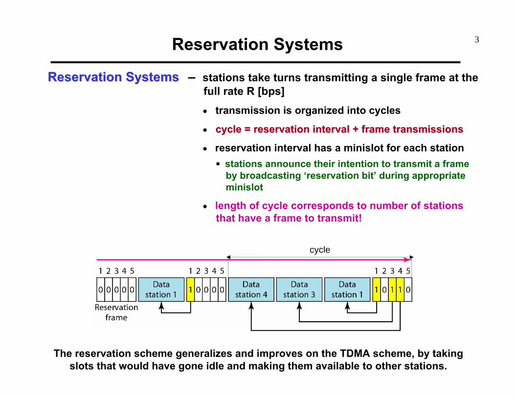
Reservation SystemsReservation Systems – stations take turns transmitting a single frame at thefull rate R [bps]• transmission is organized into cycles
• cycle = reservation interval + frame transmissionscycle = reservation interval + frame transmissions
• reservation interval has a minislot for each station stations announce their intention to transmit a frameby broadcasting ‘reservation bit’ during appropriateminislot
• length of cycle corresponds to number of stationsthat have a frame to transmit!
The reservation scheme generalizes and improves on the TDMA scheme, by takingslots that would have gone idle and making them available to other stations.
cycle

4
– assume frame transmission times = X [ sec], andminislot transmission times = v*X [sec], where 0<v<1• effective frame transmission time:
• efficiency under full load, i.e. all stations are transmitting:
• throughput in case of k-frame reservation – one minislotcan reserve up to k frames
Reservation Systems (cont.)
Efficiency ofEfficiency ofReservation SystemsReservation Systems
Xv)(1XvXt effective frame ⋅+=⋅+=
v11
MvXMXMXefficiency
bits send to time overallbits useful send to time
+=
+==
kv11
MvXkMXkMXefficiency
+=
+=
If v→0then R→1
If k>>then R→1

5Reservation Systems (cont.)
When to UseWhen to UseReservation SchemeReservation Scheme
– if most stations, most of the time, have large volumes of data to send• as k >>, overhead becomes insignificant
When When NOTNOT to Useto UseReservation SchemeReservation Scheme
1) if large number of stations transmit data infrequently• dedicating a minislot for each station is inefficient• solution: use fewer minislots to reduce overhead, make
stations content for minislots using slotted ALOHAdrawback: low efficiency under heavy traffic load
2) if propagation delay is not negligible• slots go unused, or collisions occur, because
reservations cannot take effect quickly enough
6
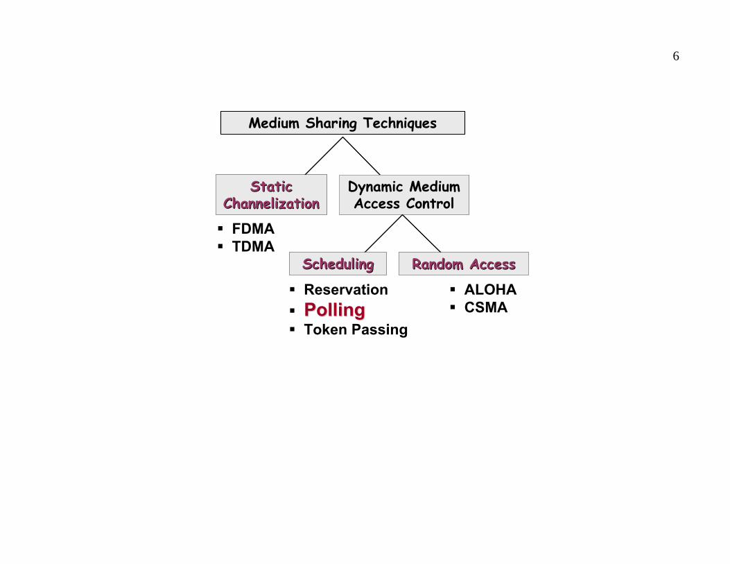
Medium Sharing Techniques
Static Static ChannelizationChannelization
Dynamic Medium Access Control
SchedulingScheduling Random AccessRandom Access
Medium Sharing Techniques
Static Static ChannelizationChannelization
Dynamic Medium Access Control
SchedulingScheduling Random AccessRandom Access
FDMATDMA
ReservationPollingPollingToken Passing
ALOHACSMA

7Polling Systems
Polling SystemsPolling Systems – one device is designated as a primary station (centralcontroller) and other devices are secondary stations• system consists of two lines
outbound line – used to transmit messages from centralcontroller to secondary stationsinbound line – shared among M stations
• central controller sends ‘polling messages’ to secondarystation, in round-robin fashion, asking them if they have anything to send
• stations have the right to transmit only if polled by central controller – at any give time only one station has the right to transmit
• completion of transmission is indicated through ‘go-aheadmessage’ – after receiving this message, central controllerpolls another station
Shared inbound line
Outbound lineCentral
controller
Shared inbound line
Outbound lineCentral
controller

8
Medium Sharing Techniques
Static Static ChannelizationChannelization
Dynamic Medium Access Control
SchedulingScheduling Random AccessRandom Access
Medium Sharing Techniques
Static Static ChannelizationChannelization
Dynamic Medium Access Control
SchedulingScheduling Random AccessRandom Access
FDMATDMA
ReservationPollingToken PassingToken Passing
ALOHACSMA
9Token-Passing Systems
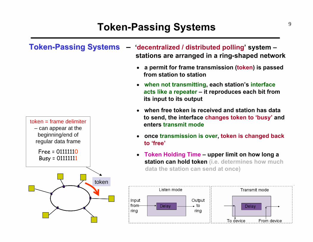
TokenToken--Passing SystemsPassing Systems – ‘decentralized / distributed polling’ system –stations are arranged in a ring-shaped network• a permit for frame transmission (token) is passed
from station to station• when not transmitting, each station’s interface
acts like a repeater – it reproduces each bit from its input to its output
• when free token is received and station has datato send, the interface changes token to ‘busy’ and enters transmit mode
• once transmission is over, token is changed backto ‘free’
• Token Holding Time – upper limit on how long astation can hold token (i.e. determines how muchdata the station can send at once)
tokentoken
token = frame delimiter– can appear at the
beginning/end of regular data frame
Free = 01111110Busy = 01111111

10
http://whale.hit.bme.hu/~remopp/DES/ExtendedApplet/index.html
Token-Passing Systems (cont.)
Example [ Token Ring Applet ]
11Token-Passing Systems (cont.)
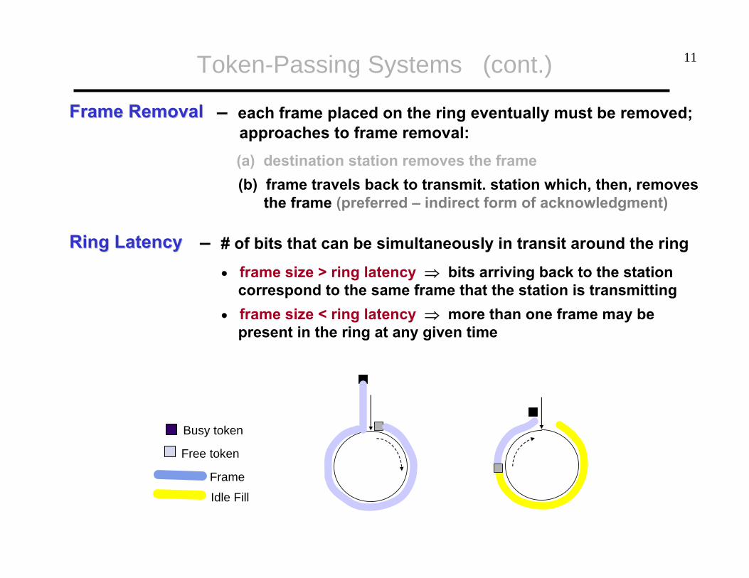
Frame RemovalFrame Removal – each frame placed on the ring eventually must be removed;approaches to frame removal:(a) destination station removes the frame(b) frame travels back to transmit. station which, then, removes
the frame (preferred – indirect form of acknowledgment)
Busy token
Free token
Frame
Idle Fill
Ring LatencyRing Latency – # of bits that can be simultaneously in transit around the ring
• frame size > ring latency ⇒ bits arriving back to the station correspond to the same frame that the station is transmitting
• frame size < ring latency ⇒ more than one frame may bepresent in the ring at any given time

12
Approaches toApproaches toToken ReleaseToken Release
(1) Delayed Token Release – aka Single-Frame Operation –insert ‘free’ token after return of entire frame
simplified ACK process – destination node signals correctreception by appending an ACK to the end of frameused in slower networks! (frame size ≈ ring latency)
(2) Early Token Release – aka Multitoken Operation – insert‘free’ token right after completion of frame transmission
time required to pass a free token minimizedif frame size << ring latency ⇒ several frames can be intransit at the same time, in different parts of the network⇒ considerably higher throughputused in faster networks! (frame size << ring latency)
Token-Passing Systems (cont.)
Busy token
Free token
Frame
Idle Fill

13Token-Passing Systems (cont.)
Throughput in Throughput in Delayed Token ReleaseDelayed Token Release
• assume:ring latency (prop. time) in sec – τ’M stations in the ring
• effective frame transmission timeeffective frame transmission time = X + prop. delay + timeto pass token to next neighbour
MXtime trans. frame effective
'' ττ ++=
average distancebetween neighboring
stations = τ’/M
time to pass tokento the neighbor
⎟⎠⎞
⎜⎝⎛ +⋅+
=⎟⎠⎞
⎜⎝⎛ +⋅+
=++
=
M11a'1
1
M11
X1
1
MX
Xefficiency ''
' τττ
Throughput in Throughput in Early Token ReleaseEarly Token Release
• effective frame transmission timeeffective frame transmission time = X + prop time to neighbour
MXtime trans. frame effective
'τ+=
Ma'1
1
M1
X1
1
MX
Xefficiency
+=
+=
+= '' ττ
a’
14Token-Passing Systems (cont.)
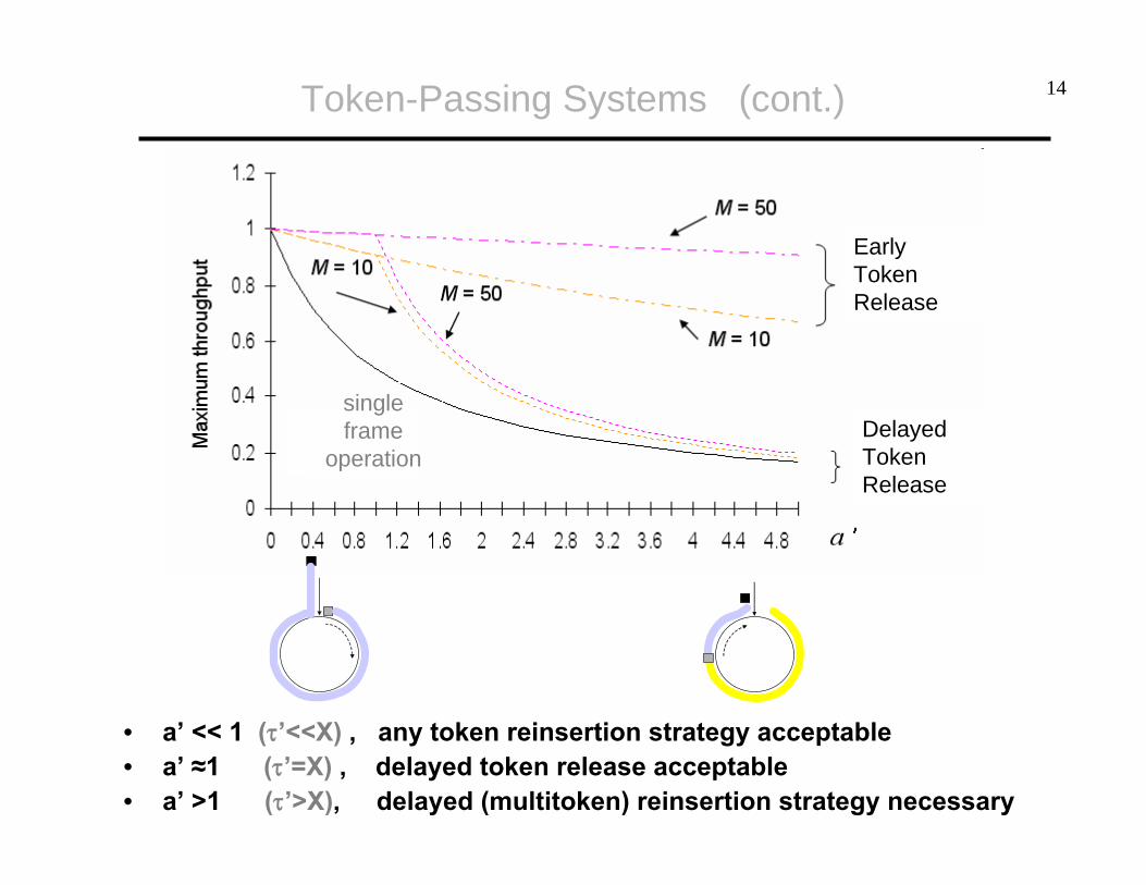
DelayedToken Release
EarlyToken Release
• a’ << 1 (τ’<<X) , any token reinsertion strategy acceptable• a’ ≈1 (τ’=X) , delayed token release acceptable• a’ >1 (τ’>X), delayed (multitoken) reinsertion strategy necessary
single frame
operation

15Random Access vs. Scheduling Access Control
Random Access(ALOHA, CSMA) Scheduling Access
delay small under light loadslonger but generally less variable between stations
throughputsufficient under light load,
drops significantly under heavy loads increases under heavy load
fairness not guaranteed guaranteed
☺
☺
sensitivity to node failure
small ☺ high, particularly in polling and token ring systems
☺

16
??? ???
24 kHz0 kHz
Telephone systems:
1) Large number of users present in the system; (only) a fraction isactive at any point in time.
2) Traffic (voice) should be transmitted with minimum delay and jitter.
Channel Sharing in Telephone Systems
17
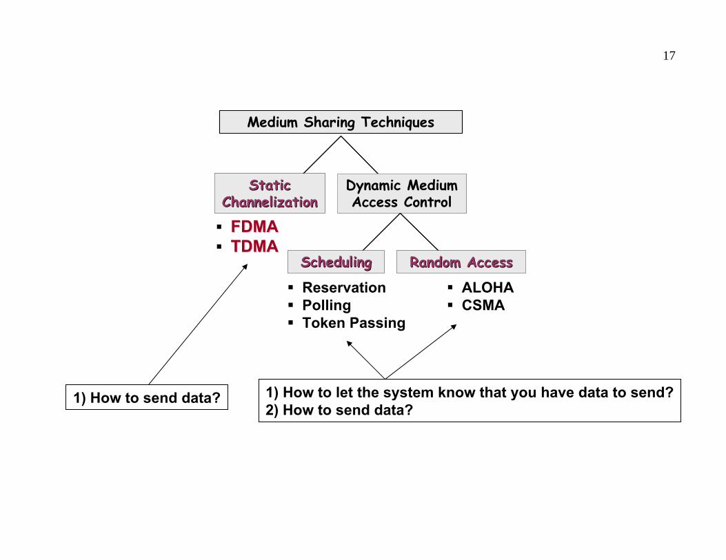
Medium Sharing Techniques
Static Static ChannelizationChannelization
Dynamic Medium Access Control
SchedulingScheduling Random AccessRandom Access
Medium Sharing Techniques
Static Static ChannelizationChannelization
Dynamic Medium Access Control
SchedulingScheduling Random AccessRandom Access
FDMAFDMATDMATDMA
ReservationPollingToken Passing
ALOHACSMA
1) How to let the system know that you have data to send?2) How to send data?
1) How to send data?

18Channelization
ChannelizationChannelization – semi-static bandwidth allocation of portion of shared medium to a given user
• highly efficient in case of constant bit-rate (streaming) traffic
• inefficient in case of (a) bursty traffic(b) when different users have different traffic requirements(c) large number of users – poor scaling
• bandwidth can be shared infrequency (FDMA) – broadcast radio/TV, analog cellular phonetime (TDMA) – telephone backbone, GSM digital cellular phonethrough code (CDMA) – 3G cellular

19FDMA
FDMFDM – Frequency Division Multiplex – analogue technique for transmittingmultiple information signals on a single communication channel• each signal is modulated with different carrier frequency – the signals
are then combined into a single composite signal• carrier frequencies are separated by sufficient bandwidth to prevent
overlapping of modulated signals in frequency domain
FDM in time domain
FDM in frequency domain

20FDMA (cont.)
FDMAFDMA – Frequency Division Multiplex Access – FDM-based technique thatenables multiple users to share the same medium• channel is divided into M separate frequency bands (so-called channels)
centered around M different carrier frequencies• to prevent interference, the channels are separated by guard bands• each band is reserved for a specific user – the user transmits its
modulated signal on the given band, without interruption• each user transmits at most R/M [bps]
Frequency
Guard bands
Time
W(R)
12
MM–1
…
Frequency
Guard bands
Time
Frequency
Guard bands
Time
W(R)
12
MM–1
…
FDMA AdvantageFDMA Advantage – easy to implement – no need for node synchronization
FDMA DisadvantageFDMA Disadvantage (1) guard bands ensure separation, but waste bandwidth(2) # of simultaneously served users ≤ # of channels
fc1
fc2
fc(M-1)
fcM
21FDMA (cont.)
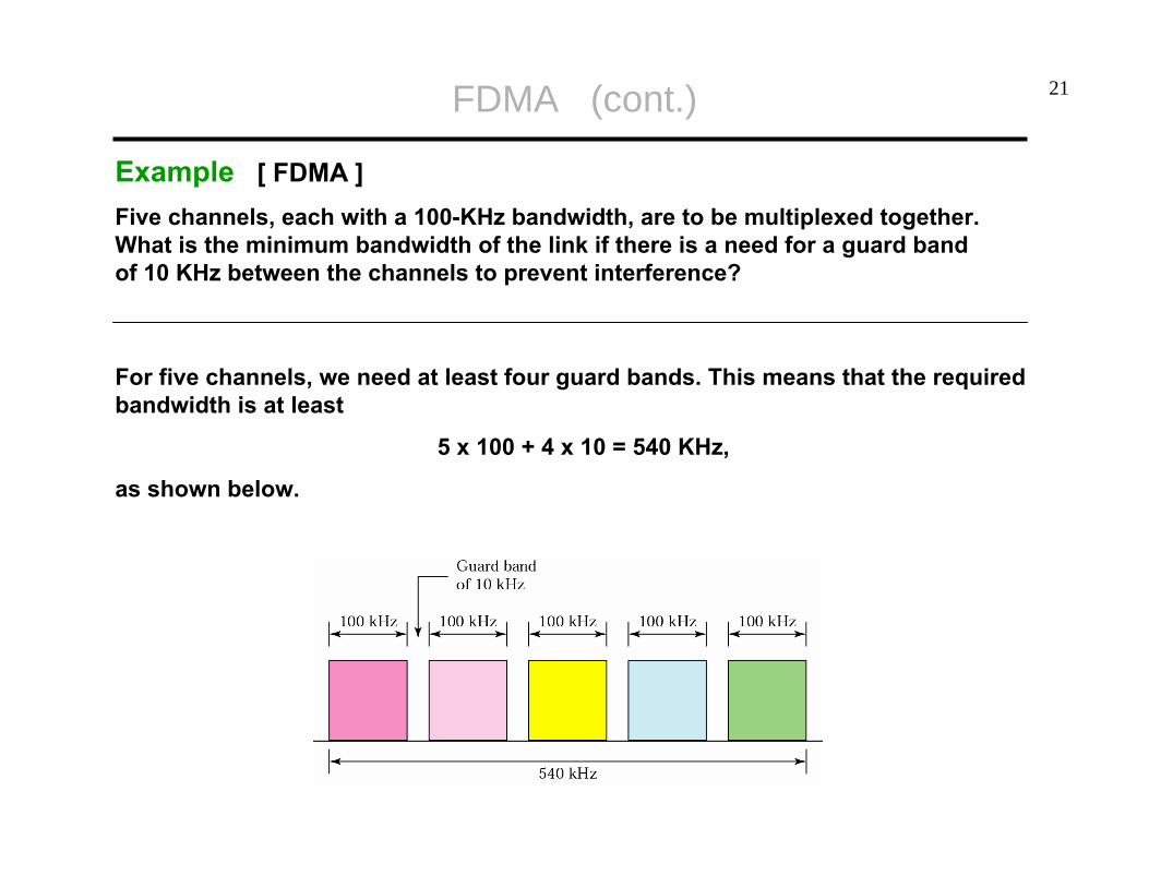
Example [ FDMA ]Five channels, each with a 100-KHz bandwidth, are to be multiplexed together. What is the minimum bandwidth of the link if there is a need for a guard bandof 10 KHz between the channels to prevent interference?
For five channels, we need at least four guard bands. This means that the required bandwidth is at least
5 x 100 + 4 x 10 = 540 KHz,
as shown below.

22FDMA (cont.)
Example [ AMPS ]The Advanced Mobile Phone System (AMPS) uses two bands. The first band,824 to 849 MHz, is used for sending; and 869 to 894 MHz is used for receiving.
Each user has a bandwidth of 30 KHz in each direction. (The 3-KHz voice is modulated using FM, creating 30 KHz of modulated signal.)
How many people can use their cellular phones simultaneously?
Each band is 25 MHz. If we divide 25 MHz into 30 KHz, we get 833.33. In reality, the band is divided into 832 channels.
23
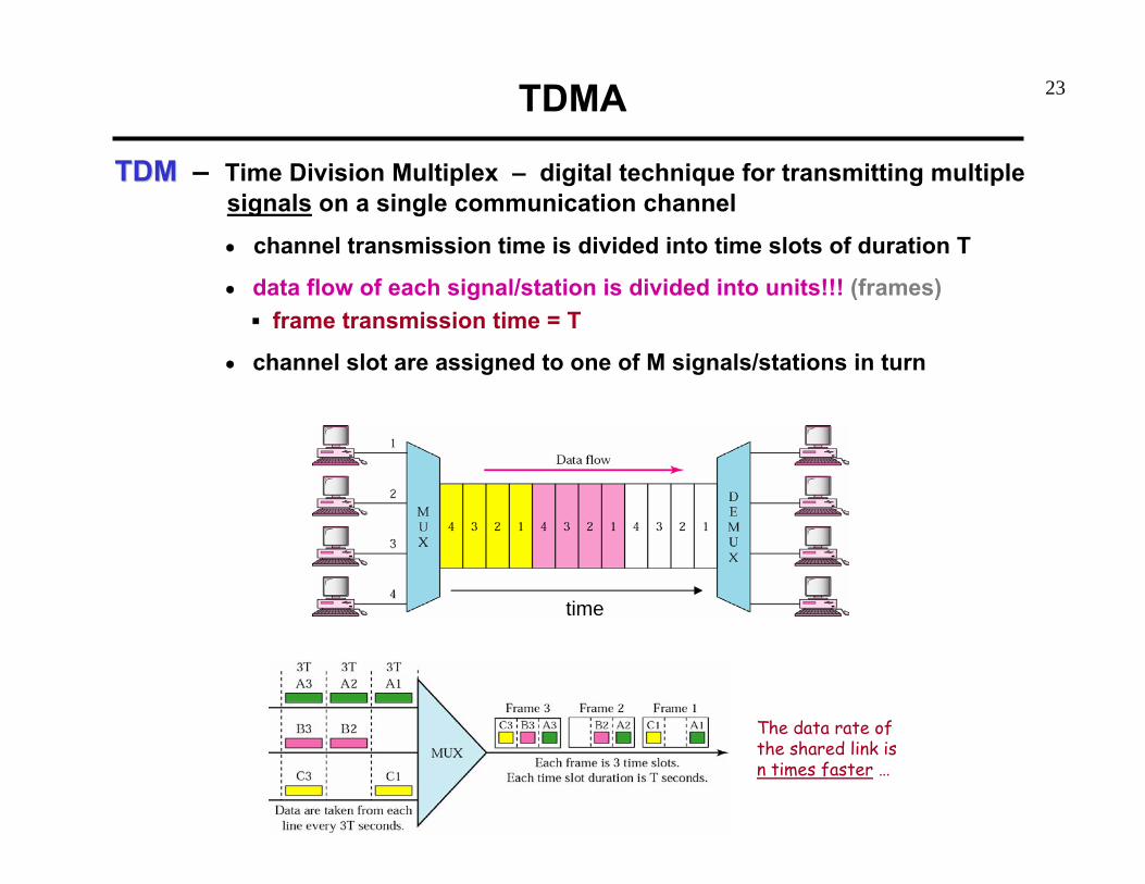
TDMTDM – Time Division Multiplex – digital technique for transmitting multiplesignals on a single communication channel• channel transmission time is divided into time slots of duration T
• data flow of each signal/station is divided into units!!! (frames)frame transmission time = T
• channel slot are assigned to one of M signals/stations in turn
TDMA
The data rate of the shared link isn times faster …
time
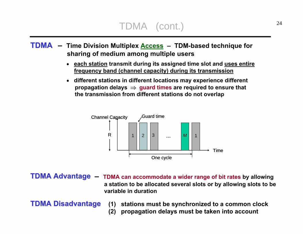
24TDMA (cont.)
TDMATDMA – Time Division Multiplex Access – TDM-based technique for sharing of medium among multiple users• each station transmit during its assigned time slot and uses entire
frequency band (channel capacity) during its transmission• different stations in different locations may experience different
propagation delays ⇒ guard times are required to ensure thatthe transmission from different stations do not overlap
TDMA AdvantageTDMA Advantage – TDMA can accommodate a wider range of bit rates by allowinga station to be allocated several slots or by allowing slots to bevariable in duration
TDMA DisadvantageTDMA Disadvantage (1) stations must be synchronized to a common clock(2) propagation delays must be taken into account
1
Time
Guard time
One cycle
12 3 MR
Channel Capacity
...1
Time
Guard time
One cycle
12 3 MR
Channel Capacity
...

25TDMA (cont.)
Example [ TDMA ]Four 1-Kbps connections are multiplexed together. Find (1) the duration of 1 bit before multiplexing, (2) the transmission rate of the shared link, (3) the duration of 1 bit after multiplexing.
(1) The duration of 1 bit before multiplexing is 1/1 Kbps, or 0.001 s (i.e. 1 ms).(2) The rate of the link is 4*1 Kbps = 4 Kbps.(3) The duration of one bit after multiplexing is 1/4 Kbps or 0.00025 s (i.e. 0.25 ms).