Embed Size (px)
Citation preview
T. Santra et al. Multiphysics modelling of a hybrid magnetic bearing (HMB) for calculating power loss andtemperature with different loss minimization strategies
MULTIPHYSICS MODELLING OF A HYBRIDMAGNETIC BEARING (HMB) FOR CALCULATING
POWER LOSS AND TEMPERATURE WITHDIFFERENT LOSS MINIMIZATION STRATEGIES
T. Santra1*, D. Roy1, A. B. Choudhury1, S. Yamada2
1Indian Institute of Engineering Science & Technology, Shibpur, Howrah, India2Division of Biological Measurement and Application, Institute of Nature and Environmental
Technology, Kanazawa University, Japan
ABSTRACT
This paper represents a multiphysics modelling for calculating loss and temperature of a hybrid magneticbearing (HMB) using finite element method (FEM). It also addresses the different loss minimization strategiesfor the HMB. The main sources of losses are identified as eddy current loss in permanent magnets, flywheeland copper loss in electromagnet. Due to these losses, the temperature distribution in different portions ofHMB is computed using coupled field analysis. To minimize the eddy current loss, slits are fabricated inflywheel plate instead of a solid flywheel. The improvement of the control current is investigated by providinga coating of different metal, like copper, brass and stainless steel on the flywheel. A zero bias current (ZBC)scheme has been introduced where no bias current is required to levitate the rotor or to avoid singularity dueto external disturbances, thus reducing the copper loss.
Keywords: Hybrid magnetic bearing, multiphysics modelling, loss, temperature
*Corresponding author: Tapan Santra ([email protected])
INTRODUCTION
Now a day’s magnetic bearing is very populardue to its contact free operation, zerolubrication, high rotational speed and almostmaintenance free operation [1]. There aredifferent type of configurations: activemagnetic bearing [2], passive magneticbearing [3, 4] and hybrid magnetic bearing [5,6]. In active magnetic bearing the rotor mass issupported by the controlled electromagnetswhereas passive magnetic bearing consists ofpermanent magnets only in attractive orrepulsive mode. A hybrid bearing consists ofelectromagnets and passive magnets both toincorporate the advantages of active andpassive bearing in a single Construction.Though magnetic bearing has a lot of
advantages, but in most of the times magneticbearing incurs a high power loss, especially inactive magnetic bearing. Passive magneticbearing has less power loss, but they sufferfrom low load carrying capacity andinstability. In a HMB power loss is reduced byincorporating permanent magnets along withelectromagnets. So power loss calculation in amagnetic bearing is very much essential. Inmost of the literatures, bearing design andcontrol has been reported; there are very fewworks which report on the power lossestimation and minimization in a magneticbearing. Kandil et al.[7] addressed a slidingmode control of a hybrid magnetic bearing forwayside flywheel energy storage Systems.Hou Eryong and Liu Kun [8] developed aradial hybrid magnetic bearing (RHMB),
TRIBOLOGIA - Finnish Journal of Tribology 1-2 vol 36/2019 24
T. Santra et al. Multiphysics modelling of a hybrid magnetic bearing (HMB) for calculating power loss andtemperature with different loss minimization strategies
which has integration of electromagnet andpassive magnets along with continuousworking air gaps that reduce the losses of thetraditional homopolar structure. Xu Yanlianget al.[8] represented a FEM analysis of a hybridmagnetic bearing where permanent magnetwas installed in the rotor. Li Ji et al.[10]reported the work on a six-pole heteropolarradial hybrid magnetic bearing (HMB) whichis only 13.35% power consumption of atraditional eight-pole active magnetic bearingwith the same load capacity. L. Bakay et al.[11] designed and optimized a radial activemagnetic bearings (RAMB) and PM-biasedhybrid Radial magnetic bearings (HRMB) forflywheel long term energy storage (LTFES).
Although many works are reported onmodelling and control of HMB and a fewworks on loss calculation and reduction, to thebest of the author’s knowledge, no work hasbeen reported in the literature on thetemperature modelling of a hybrid magneticbearing (HMB). Mukhopadhyay et al.[12]proposed a single axis controlled repulsivetype magnetic bearing which is passivelystable in the radial direction by meanspermanent magnets and axially controlled by asingle electromagnet with hollow cylindrical
core. So this type of construction isinexpensive. This paper addressed the loss andtemperature modelling with different lossminimization strategies for this single axiscontrolled HMB. Eddy current loss iscalculated in passive magnets and flywheeland it is observed that by providing slits in theflywheel eddy current loss can be reduced.With increased rotor speed the eddy currentinfluences the control current which increasesthe copper loss in electromagnet. It is evidentthat the most vital loss occurs in HMB is the
2i R loss in the electromagnet coil due to thebiasing current ( biasingi ). The biasing current isunavoidable as it is essential to levitate therotor mass and to avoid singularity whenexternal disturbance comes. A new zero biascurrent control (ZBC) scheme is developed bymodifying the existing configuration of HMB,where bias current is no more required and thusdrastically decreases the power loss. After thecalculation the loss data from the Maxwell -transient setup is transferred to TransientThermal set-up of ANSYS using the coupledfield analysis (CFA). Thus a Multiphysicsmodelling of HMB has been carried out tocouple electromagnetic and thermal.
(a) (b)
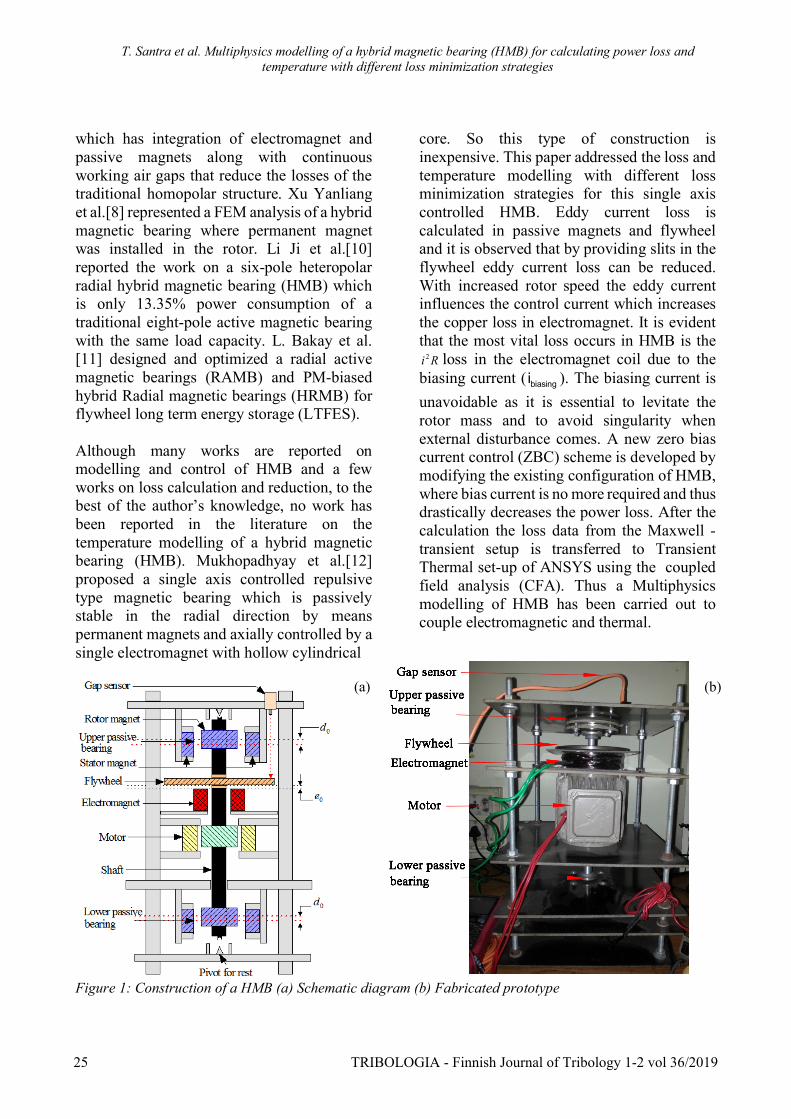
Figure 1: Construction of a HMB (a) Schematic diagram (b) Fabricated prototype
25 TRIBOLOGIA - Finnish Journal of Tribology 1-2 vol 36/2019
T. Santra et al. Multiphysics modelling of a hybrid magnetic bearing (HMB) for calculating power loss andtemperature with different loss minimization strategies
Table 1 Dimensions and parameters of the HMBHMBComponents
Material, Dimensions and PropertiesRotor magnet Material: NdFeB, Ring shaped, Inner dia: 10 mm Outer dia: 30 mm Thickness:10
mm Coercivity Hc=106 A/m, remanence Br = 1.257 T, density = 0.271 lb/in3,electrical conductivity = 0.625 MS/m.
Stator magnet Material: NdFeB, Ring shaped, Inner dia: 36 mm, Outer dia: 52 mm, Thickness:10mm, Coercivity Hc=106 A/m, remanence Br = 1.257 T, density = 0.271 lb/in3,electrical conductivity = 0.625 MS/m
Electromagnet Core material: Steel, Coil material: Copper, Hollow cylindrical type core, Coreinner dia:20 mm , Core outer dia: 70 mm,Thickness: 25 mm , Coil inner dia: 70mm , Coil outer dia: 98 mm, Number of turns: 1295 nos, Elctro magnet constant
ek = -4 2 -26.65×10 Nm A , resistance eR = 2.5W ,inductance eL = 0.5 HFlywheel Material: Stainless steel, Dia: 110 mm, Thickness: 2.5 mmRotor Material: Steel, 4.5 Kg
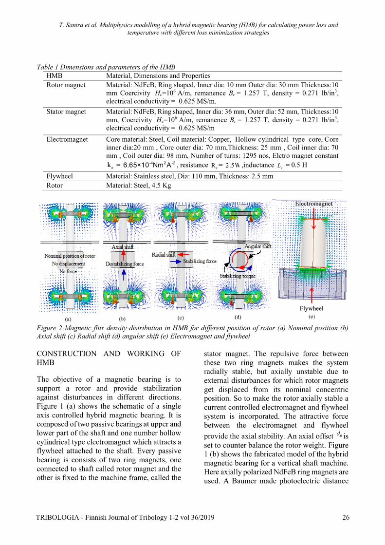
Figure 2 Magnetic flux density distribution in HMB for different position of rotor (a) Nominal position (b)Axial shift (c) Radial shift (d) angular shift (e) Electromagnet and flywheel
CONSTRUCTION AND WORKING OFHMB
The objective of a magnetic bearing is tosupport a rotor and provide stabilizationagainst disturbances in different directions.Figure 1 (a) shows the schematic of a singleaxis controlled hybrid magnetic bearing. It iscomposed of two passive bearings at upper andlower part of the shaft and one number hollowcylindrical type electromagnet which attracts aflywheel attached to the shaft. Every passivebearing is consists of two ring magnets, oneconnected to shaft called rotor magnet and theother is fixed to the machine frame, called the
stator magnet. The repulsive force betweenthese two ring magnets makes the systemradially stable, but axially unstable due toexternal disturbances for which rotor magnetsget displaced from its nominal concentricposition. So to make the rotor axially stable acurrent controlled electromagnet and flywheelsystem is incorporated. The attractive forcebetween the electromagnet and flywheelprovide the axial stability. An axial offset 0d isset to counter balance the rotor weight. Figure1 (b) shows the fabricated model of the hybridmagnetic bearing for a vertical shaft machine.Here axially polarized NdFeB ring magnets areused. A Baumer made photoelectric distance
TRIBOLOGIA - Finnish Journal of Tribology 1-2 vol 36/2019 26
T. Santra et al. Multiphysics modelling of a hybrid magnetic bearing (HMB) for calculating power loss andtemperature with different loss minimization strategies
sensor (OADM 12U6460/S35A) is used tosense the axial displacement of the rotor andfeed it back to DSP based controller to controlthe current in the electromagnet coilaccordingly. A LEM make current sensor(LTS 25NP) is used to sense the coil current.The dimension and properties of differentcomponents of this HMB are listed in Table 1.
Figure 2 represents the magnetic flux densitydistribution in passive magnetic system atupper and lower passive bearing for differentpositions of the rotor: (a) nominal position, (b)axially shifted position, (c) radially shiftedposition, (d) tilting. It is observed that atdifferent positions of rotor, different type offorces act on the rotor. At the nominalcondition, no force, at axially shifted positiona destabilizing force, at radially shiftedposition a stabilizing force, at tilting a restoringtorque. It is also observed that in all these casesthe flux density distribution is nonuniform innature, so as the rotor magnet rotates in thismagnetic field an eddy current loss will occur.Figure 2 (e) shows for flux density distributionin the electromagnet - flywheel system. Sowhen rotor experiences a radial shift or tilting,eddy current loss will be there in a flywheel.
LOSS CALCULATION ANDMINIMIZATION
Eddy current loss in permanent magnets
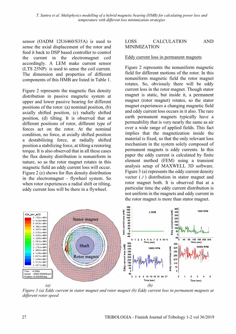
Figure 2 represents the nonuniform magneticfield for different motions of the rotor. In thisnonuniform magnetic field the rotor magnetrotates. So, obviously there will be eddycurrent loss in the rotor magnet. Though statormagnet is static, but inside it, a permanentmagnet (rotor magnet) rotates, so the statormagnet experiences a changing magnetic fieldand eddy current loss occurs in it also. The rareearth permanent magnets typically have apermeability that is very nearly the same as airover a wide range of applied fields. This factimplies that the magnetization inside thematerial is fixed, so that the only relevant lossmechanism in the system solely composed ofpermanent magnets is eddy currents. In thispaper the eddy current is calculated by finiteelement method (FEM) using a transientanalysis setup of MAXWELL 3D software.Figure 3 (a) represents the eddy current densityvector ( J ) distribution in stator magnet androtor magnet both. It is observed that at aparticular time the eddy current distribution isnot uniform in the magnets and eddy current inthe rotor magnet is more than stator magnet.
(a) (b)Figure 3 (a) Eddy current in stator magnet and rotor magnet (b) Eddy current loss in permanent magnets atdifferent rotor speed
27 TRIBOLOGIA - Finnish Journal of Tribology 1-2 vol 36/2019
T. Santra et al. Multiphysics modelling of a hybrid magnetic bearing (HMB) for calculating power loss andtemperature with different loss minimization strategies
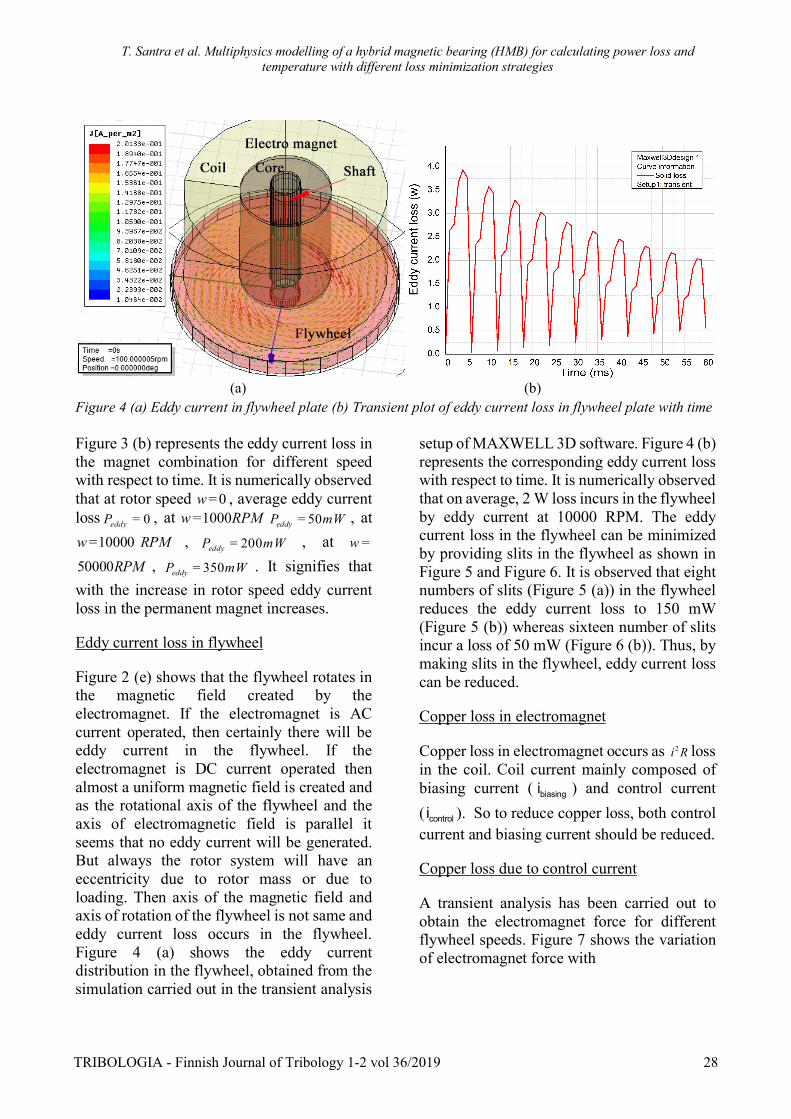
(a) (b)Figure 4 (a) Eddy current in flywheel plate (b) Transient plot of eddy current loss in flywheel plate with time
Figure 3 (b) represents the eddy current loss inthe magnet combination for different speedwith respect to time. It is numerically observedthat at rotor speed 0w = , average eddy currentloss 0eddyP = , at 1000RPMw = 50eddyP mW= , at
10000w = RPM , 200eddyP mW= , at w =
50000RPM , 350eddyP mW= . It signifies thatwith the increase in rotor speed eddy currentloss in the permanent magnet increases.
Eddy current loss in flywheel
Figure 2 (e) shows that the flywheel rotates inthe magnetic field created by theelectromagnet. If the electromagnet is ACcurrent operated, then certainly there will beeddy current in the flywheel. If theelectromagnet is DC current operated thenalmost a uniform magnetic field is created andas the rotational axis of the flywheel and theaxis of electromagnetic field is parallel itseems that no eddy current will be generated.But always the rotor system will have aneccentricity due to rotor mass or due toloading. Then axis of the magnetic field andaxis of rotation of the flywheel is not same andeddy current loss occurs in the flywheel.Figure 4 (a) shows the eddy currentdistribution in the flywheel, obtained from thesimulation carried out in the transient analysis
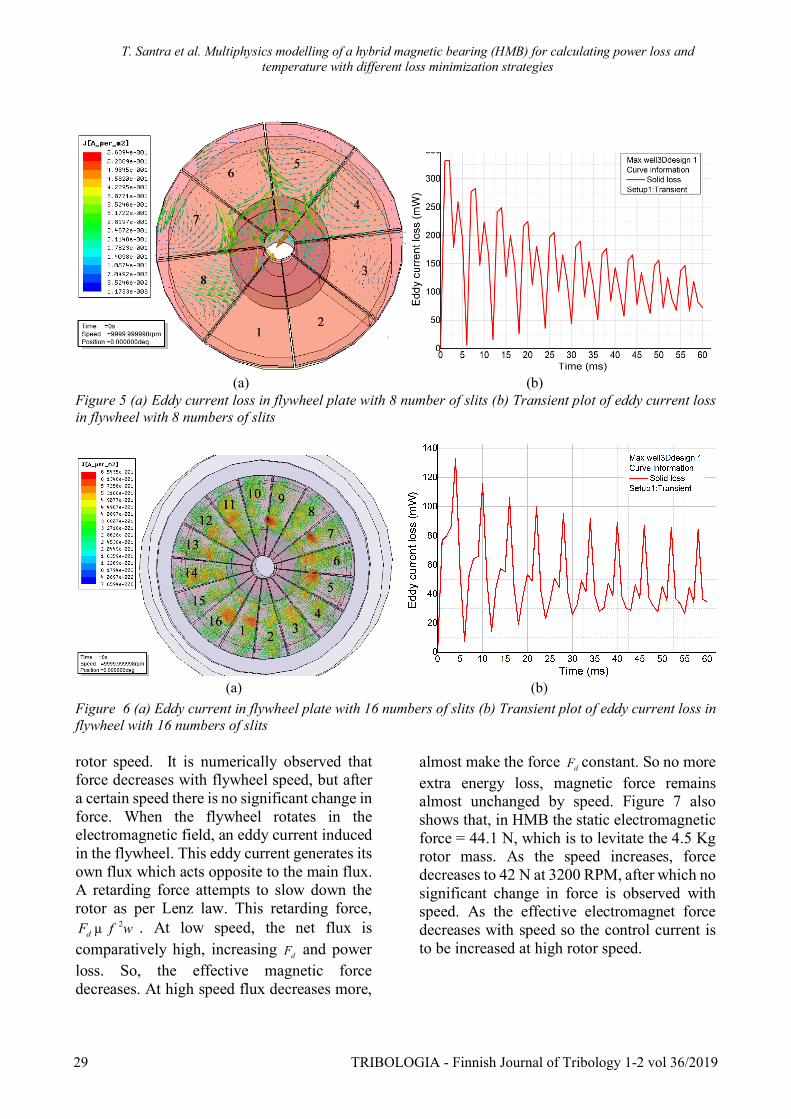
setup of MAXWELL 3D software. Figure 4 (b)represents the corresponding eddy current losswith respect to time. It is numerically observedthat on average, 2 W loss incurs in the flywheelby eddy current at 10000 RPM. The eddycurrent loss in the flywheel can be minimizedby providing slits in the flywheel as shown inFigure 5 and Figure 6. It is observed that eightnumbers of slits (Figure 5 (a)) in the flywheelreduces the eddy current loss to 150 mW(Figure 5 (b)) whereas sixteen number of slitsincur a loss of 50 mW (Figure 6 (b)). Thus, bymaking slits in the flywheel, eddy current losscan be reduced.
Copper loss in electromagnet
Copper loss in electromagnet occurs as 2i R lossin the coil. Coil current mainly composed ofbiasing current ( biasingi ) and control current( controli ). So to reduce copper loss, both controlcurrent and biasing current should be reduced.
Copper loss due to control current
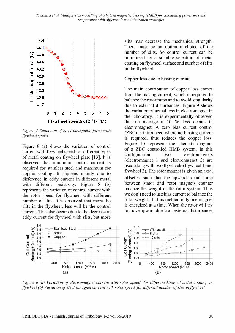
A transient analysis has been carried out toobtain the electromagnet force for differentflywheel speeds. Figure 7 shows the variationof electromagnet force with
TRIBOLOGIA - Finnish Journal of Tribology 1-2 vol 36/2019 28
T. Santra et al. Multiphysics modelling of a hybrid magnetic bearing (HMB) for calculating power loss andtemperature with different loss minimization strategies
(a) (b)Figure 5 (a) Eddy current loss in flywheel plate with 8 number of slits (b) Transient plot of eddy current lossin flywheel with 8 numbers of slits
(a) (b)Figure 6 (a) Eddy current in flywheel plate with 16 numbers of slits (b) Transient plot of eddy current loss inflywheel with 16 numbers of slits
rotor speed. It is numerically observed thatforce decreases with flywheel speed, but aftera certain speed there is no significant change inforce. When the flywheel rotates in theelectromagnetic field, an eddy current inducedin the flywheel. This eddy current generates itsown flux which acts opposite to the main flux.A retarding force attempts to slow down therotor as per Lenz law. This retarding force,
2dF f wµ . At low speed, the net flux is
comparatively high, increasing dF and powerloss. So, the effective magnetic forcedecreases. At high speed flux decreases more,
almost make the force dF constant. So no moreextra energy loss, magnetic force remainsalmost unchanged by speed. Figure 7 alsoshows that, in HMB the static electromagneticforce = 44.1 N, which is to levitate the 4.5 Kgrotor mass. As the speed increases, forcedecreases to 42 N at 3200 RPM, after which nosignificant change in force is observed withspeed. As the effective electromagnet forcedecreases with speed so the control current isto be increased at high rotor speed.
29 TRIBOLOGIA - Finnish Journal of Tribology 1-2 vol 36/2019
T. Santra et al. Multiphysics modelling of a hybrid magnetic bearing (HMB) for calculating power loss andtemperature with different loss minimization strategies
Figure 7 Reduction of electromagnetic force withflywheel speed
Figure 8 (a) shows the variation of controlcurrent with flywheel speed for different typesof metal coating on flywheel plate [13]. It isobserved that minimum control current isrequired for stainless steel and maximum forcopper coating. It happens mainly due todifference in eddy current in different metalwith different resistivity. Figure 8 (b)represents the variation of control current withthe rotor speed for flywheel with differentnumber of slits. It is observed that more theslits in the flywheel, less will be the controlcurrent. This also occurs due to the decrease ineddy current for flywheel with slits, but more
slits may decrease the mechanical strength.There must be an optimum choice of thenumber of slits. So control current can beminimized by a suitable selection of metalcoating on flywheel surface and number of slitsin the flywheel.
Copper loss due to biasing current
The main contribution of copper loss comesfrom the biasing current, which is required tobalance the rotor mass and to avoid singularitydue to external disturbances. Figure 9 showsthe variation of actual loss in electromagnet inthe laboratory. It is experimentally observedthat on average a 10 W loss occurs inelectromagnet. A zero bias current control(ZBC) is introduced where no biasing currentis required, thus reduces the copper loss.Figure 10 represents the schematic diagramof a ZBC controlled HMB system. In thisconfiguration two electromagnets(electromagnet 1 and electromagnet 2) areused along with two flywheels (flywheel 1 andflywheel 2). The rotor magnet is given an axialoffset 0x such that the upwards axial forcebetween stator and rotor magnets counterbalance the weight of the rotor system. Thuswe don’t need to use bias current to balance therotor weight. In this method only one magnetis energized at a time. When the rotor will tryto move upward due to an external disturbance,
Figure 8 (a) Variation of electromagnet current with rotor speed for different kinds of metal coating onflywheel (b) Variation of electromagnet current with rotor speed for different number of slits in flywheel
(a) (b)
TRIBOLOGIA - Finnish Journal of Tribology 1-2 vol 36/2019 30

T. Santra et al. Multiphysics modelling of a hybrid magnetic bearing (HMB) for calculating power loss andtemperature with different loss minimization strategies
Figure 9 Actual loss in electromagnet from testing
Figure 10 Schematic of ZBC-HMB system
electromagnet-2 will be energizedinstantaneously and it will attract theflywheel to pull it down, again when thesystem will try to move downward theupper electromagnet-1 will be energized topull the flywheel up. Thus the singularity inthe system due to external disturbances canbe avoided. A sliding mode controller isdesigned to control the system. A gapsensor senses the axial displacement of therotor and send a feedback signal to thecontroller. The controller sends current
signals ( 1 2,i i ) to the electromagnetsaccording to the position of the flywheel toset the flywheel in its desired position.
TEMPERATURE MODELLING OFHMB
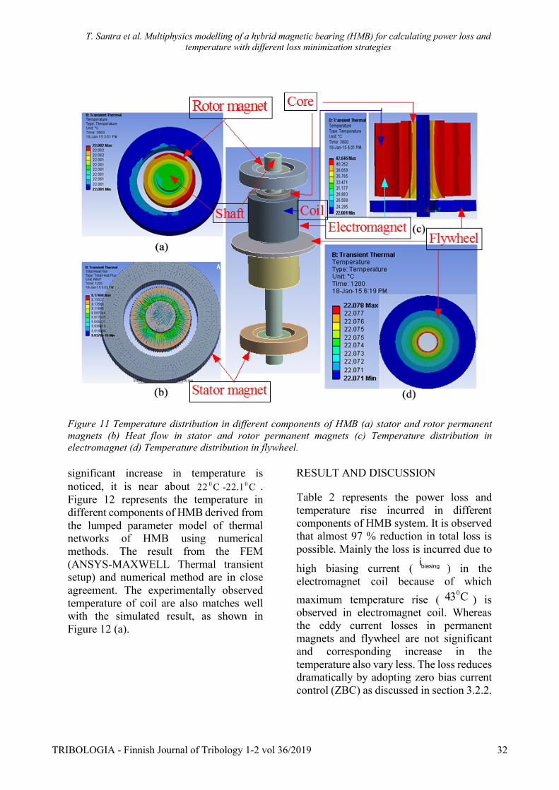
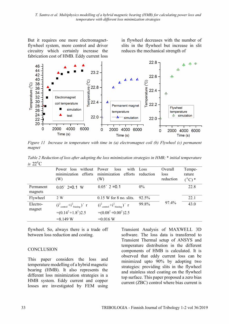
The loss calculation of HMB is carried outby FEM using Transient Analysis setup ofANSYS-MAXWELL 3D software asdiscussed in section 3. The loss data aretransferred to Transient Thermal analysissetup in ANSYS. Figure 11 shows thetemperature distribution in differentcomponents of HMB. Figure 11(a) showsthe thermal distribution and Figure 11 (b)presents the heat flow in stator and rotorpermanent magnets respectively. It isobserved that the increase in temperature inthe stator and rotor permanent magnets isnot significant ( 0 022 C -22.8 C ). Naturallythe temperature inside the rotor magnet ismore than the stator magnet as eddy currentin rotor magnet is more than the statormagnet (see Figure 3 (a)). Figure 11 (c)shows the thermal distribution inelectromagnet. The maximum temperatureis observed in the electromagnet coil due tohuge 2i r loss, near about 043 C and thesteel core temperature is increased about
038 C . Figure 11 (d) represents the thermaldistribution inside metal flywheel. No
31 TRIBOLOGIA - Finnish Journal of Tribology 1-2 vol 36/2019
T. Santra et al. Multiphysics modelling of a hybrid magnetic bearing (HMB) for calculating power loss andtemperature with different loss minimization strategies
Figure 11 Temperature distribution in different components of HMB (a) stator and rotor permanentmagnets (b) Heat flow in stator and rotor permanent magnets (c) Temperature distribution inelectromagnet (d) Temperature distribution in flywheel.
significant increase in temperature isnoticed, it is near about 0 022 C -22.1 C .Figure 12 represents the temperature indifferent components of HMB derived fromthe lumped parameter model of thermalnetworks of HMB using numericalmethods. The result from the FEM(ANSYS-MAXWELL Thermal transientsetup) and numerical method are in closeagreement. The experimentally observedtemperature of coil are also matches wellwith the simulated result, as shown inFigure 12 (a).
RESULT AND DISCUSSION
Table 2 represents the power loss andtemperature rise incurred in differentcomponents of HMB system. It is observedthat almost 97 % reduction in total loss ispossible. Mainly the loss is incurred due to
high biasing current ( biasingi ) in theelectromagnet coil because of whichmaximum temperature rise (
043 C ) isobserved in electromagnet coil. Whereasthe eddy current losses in permanentmagnets and flywheel are not significantand corresponding increase in thetemperature also vary less. The loss reducesdramatically by adopting zero bias currentcontrol (ZBC) as discussed in section 3.2.2.
TRIBOLOGIA - Finnish Journal of Tribology 1-2 vol 36/2019 32
T. Santra et al. Multiphysics modelling of a hybrid magnetic bearing (HMB) for calculating power loss andtemperature with different loss minimization strategies
But it requires one more electromagnet-flywheel system, more control and drivercircuitry which certainly increase thefabrication cost of HMB. Eddy current loss
in flywheel decreases with the number ofslits in the flywheel but increase in slitreduces the mechanical strength of
Figure 11 Increase in temperature with time in (a) electromagnet coil (b) Flywheel (c) permanentmagnet
Table 2 Reduction of loss after adopting the loss minimization strategies in HMB; * initial temperatureis 022 C
Power loss withoutminimization efforts(W)
Power loss withminimization efforts(W)
Lossreduction
Overalllossreduction
Tempe-rature
0( C) *
Permanentmagnets
0.05 2´ =0.1 W 0.05 2´ =0.1 0%
97.4%
22.8
Flywheel 2 W 0.15 W for 8 no. slits. 92.5% 22.1Electro-magnet
2 2control biasing
2 2
(i +i ) r
=(0.14 +1.8 )2.5=8.149 W
´ 2 2control biasing
2 2
(i +i ) r
=(0.08 +0.00 )2.5=0.016 W
´ 99.8% 43.0
flywheel. So, always there is a trade offbetween loss reduction and costing.
CONCLUSION
This paper considers the loss andtemperature modelling of a hybrid magneticbearing (HMB). It also represents thedifferent loss minimization strategies in aHMB system. Eddy current and copperlosses are investigated by FEM using
Transient Analysis of MAXWELL 3Dsoftware. The loss data is transferred toTransient Thermal setup of ANSYS andtemperature distribution in the differentcomponents of HMB is calculated. It isobserved that eddy current loss can beminimized upto 90% by adopting twostrategies: providing slits in the flywheeland stainless steel coating on the flywheeltop surface. This paper proposed a zero biascurrent (ZBC) control where bias current is
33 TRIBOLOGIA - Finnish Journal of Tribology 1-2 vol 36/2019
T. Santra et al. Multiphysics modelling of a hybrid magnetic bearing (HMB) for calculating power loss andtemperature with different loss minimization strategies
no more required, thus drastically reducesthe copper loss in the electromagnet coil. Itis possible to reduce the power loss about90% after considering all the loss reductionstrategies. It is also observed that maximumtemperature appears in electromagnet( 043 C) and there are no significant changesin temperature in flywheel and permanentmagnets.
ACKNOWLEDGEMENT
This research work is sponsored by theScience and Engineering Research Board(SERB), Department of Science &Technology (DST), New Delhi, India, ordernumber SR/S3/EECE/0164/2012.
REFERENCES
[1] Fang, J., Le, Y., Sun, J., and Wang, K.,Analysis and Design of PassiveMagnetic Bearing and Damping Systemfor High-Speed Compressor, IEEETrans. Magn., 2012, 48 (9), 2528–2537.https://doi.org/10.1109/TMAG.2012.2196443
[2] Matsumura, F. and Kodayashi, H.,Fundamental Equation for HorizontalShaft magnetic Bearing and its ControlSystem Design, Journal of ElectricalEngineering, Japan, 198,101C(6),137-144.
[3] Yonnet, J. P. Passive magnetic bearingwith permanent magnets, IEEE Trans.Magn. 1978,14(5), 803-805.https://doi.org/10.1109/TMAG.1978.1060019
[4] T. Santra, D. Roy and A. B. Choudhury,Calculation of Passive Magnetic Forcein a Radial Magnetic Bearing UsingGeneral Division Approach, Progress inElectromagnetics Research M, Vol. 54,pp. 91–102, February 2017.https://doi.org/10.2528/PIERM16120602
[5] Haoze Wang, Kun Liu, and Peng Ao,Magnetic Field and Specific Axial LoadCapacity of Hybrid Magnetic Bearing,IEEE Trans. Magn., 2013, 49 (8), 4911-4017.https://doi.org/10.1109/TMAG.2013.2248162
[6] Tapan Santra, Debabrata Roy,Amalendu B Choudhury and SotoshiYamada, Vibration control of a hybridmagnetic bearing using an adaptivesliding mode technique, Journal ofVibration and Control (JVC).https://doi.org/10.1177/1077546317717884
[7] Mohamed S. Kandil, Maxime R. Duboisand Joao P. Trovao, A Sliding ModeControl of a Hybrid Magnetic Bearingfor Wayside Flywheel Energy StorageSystems, Vehicle Power and PropulsionConference (VPPC), 2015, IEEEhttps://doi.org/10.1109/VPPC.2015.7352883
[8] Hou Eryong and Liu Kun, A NovelStructure for Low-Loss Radial HybridMagnetic Bearing, IEEE Trans. Magn.,2011, 47(12), 4725-4733.https://doi.org/10.1109/TMAG.2011.2160649
[9] Yanliang, Xu, et al., Analysis of HybridMagnetic Bearing With a PermanentMagnet in the Rotor by FEM, IEEETrans. Magn., 2006, 42(4),1363-1366.https://doi.org/10.1109/TMAG.2006.871396
[10] Li Ji, Longxiang Xu, and Chaowu Jin,Research on a Low Power ConsumptionSix-Pole Heteropolar Hybrid MagneticBearing, IEEE Trans. Magn., 2013,49(8), 4918-4926.https://doi.org/10.1109/TMAG.2013.2238678
[11] Bakay, L., Dubois, M. and Viarouge,P., Losses in hybrid and active magneticbearings applied to Long TermFlywheel Energy Storage, PowerElectronics, Machines and Drives(PEMD 2010), 5th IET InternationalConference on, 2010.https://doi.org/10.1049/cp.2010.0067
TRIBOLOGIA - Finnish Journal of Tribology 1-2 vol 36/2019 34
T. Santra et al. Multiphysics modelling of a hybrid magnetic bearing (HMB) for calculating power loss andtemperature with different loss minimization strategies
[12] Mukhopadhyay, S. C. et al., A NewRepulsive Type magnetic Bearing -Modeling and Control, IEEE PEDSConference, Singapore, May 26-29,1997
[13] Mukhopadhyay, S. C., Modeling of aRepulsive Type Magnetic Bearing forFive Axis Control Under IntermittentOperation Including Eddy CurrentEffect, Proceedings of the First IEEEInternational Workshop on ElectronicDesign, Test and Applications(DELTA.02), 2002,7(02)
35 TRIBOLOGIA - Finnish Journal of Tribology 1-2 vol 36/2019