Embed Size (px)
Citation preview
IN208102017 © Chief Automotive Technologies CO9910.4 Rev. - 2/14/17
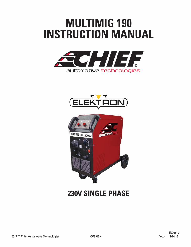
MULTIMIG 190INSTRUCTION MANUAL
230V SINGLE PHASE
2
INSTRUCTION MANUAL FOR WIRE WELDING MACHINE
IMPORTANT: BEFORE STARTING THE EQUIPMENT, READ THE CONTENTS OF THIS MANUAL, WHICH MUST BE STORED IN A PLACE FAMILIAR TO ALL USERS FOR THE ENTIRE OPERATIVE LIFE-SPAN OF THE MACHINE. THIS EQUIPMENT MUST BE USED SOLELY FOR WELDING OPERATIONS.
1. SAFETY PRECAUTIONS WELDING AND ARC CUTTING CAN BE HARMFUL TO YOURSELF AND OTHERS. The user must be educated on hazards, summarized below, deriving from welding operations. For more detailed informa-tion, order the manual. ELECTRIC SHOCK - May be fatal. Install and ground the welding machine according to the applicable regulations. Do not touch live electrical parts or electrodes with bare skin, gloves or wet clothing. Isolate yourself from both the ground and the workpiece. Make sure your working position is safe. FUMES AND GASES - May be hazardous to your health. Work in the presence of adequate ventilation and use ventilators around the arc to prevent gases from forming in the work area. ARC RAYS - May injure the eyes and burn the skin. Protect your eyes with welding masks fitted with filtered lenses and protect your body with appropriate safety protection. Protect others by installing adequate shields or curtains. RISK OF FIRE AND BURNS Sparks (sprays) may cause fires and burn the skin; make sure there are no flammable materials in the area, and wear appropriate protection. NOISE This machine does not directly produce noise exceeding 80dB. The plasma cutting/welding procedure may produce noise levels beyond said limit; users must therefore implement all precautions required by law. PACEMAKERS The magnetic fields created by high currents may affect the operation of pacemakers. Persons with vital electronic equipment (pacemakers) should consult their physician before beginning any arc welding, cutting, gouging or spot welding operations. EXPLOSIONS Do not weld in the vicinity of containers under pressure, or in the presence of explosive dust, gases or fumes. All cylinders and pressure regulators used in welding operations should be handled with care. ELECTROMAGNETIC COMPATIBILITY This machine is manufactured in compliance with the instructions contained in the harmonized standard and must be used solely for professional purposes in an industrial environment. There may be potential difficulties in ensuring electromag-netic compatibility in non-industrial environments. IN CASE OF MALFUNCTIONS, REQUEST ASSISTANCE FROM QUALIFIED PERSONNEL.
3
2. GENERAL TECHNICAL DESCRIPTIONS
2.1 SPECIFICATIONS
This manual has been prepared with the intent of instructing the operator on how to install, operate, and properly maintain this electric arc welding machine. This machine is a constant voltage power source for MIG/MAG and OPEN-ARC welding. Upon receiving and unpacking the machine, make a careful inspection to ensure that there are no damaged parts. Should there be a claim for losses or damages it must be made by the purchaser directly to the shipper who handled the goods. When requesting information about this welding machine please state the machine’s part number and serial number to ensure receiving accurate information relating to your machine.
2.2 DESCRIPTION OF TECHNICAL SPECIFICATIONS MODEL: Meets EN 60974-10:2003 International standards. SN Machine Serial Number which must appear on requests or inquiries concerning the machine.
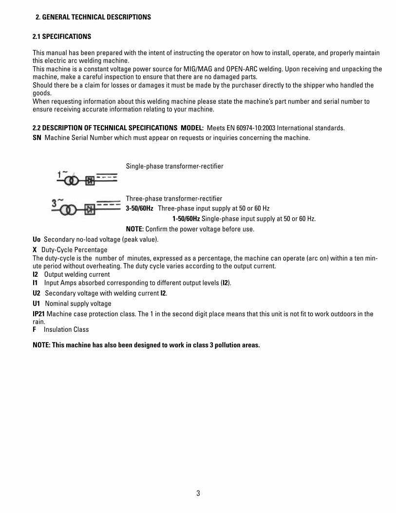
Single-phase transformer-rectifier
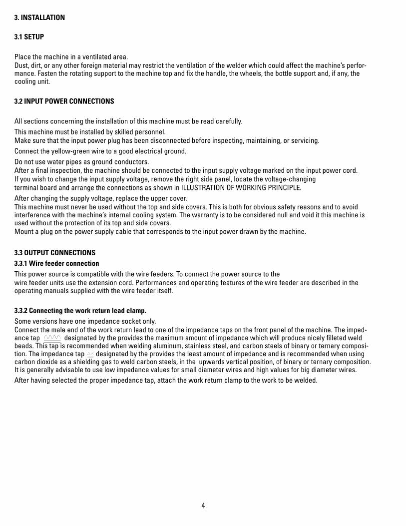
Three-phase transformer-rectifier 3-50/60Hz Three-phase input supply at 50 or 60 Hz 1-50/60Hz Single-phase input supply at 50 or 60 Hz. NOTE: Confirm the power voltage before use.Uo Secondary no-load voltage (peak value). X Duty-Cycle Percentage The duty-cycle is the number of minutes, expressed as a percentage, the machine can operate (arc on) within a ten min-ute period without overheating. The duty cycle varies according to the output current.I2 Output welding current I1 Input Amps absorbed corresponding to different output levels (I2). U2 Secondary voltage with welding current I2. U1 Nominal supply voltage IP21 Machine case protection class. The 1 in the second digit place means that this unit is not fit to work outdoors in the rain. F Insulation Class
NOTE: This machine has also been designed to work in class 3 pollution areas.
4
3. INSTALLATION
3.1 SETUP
Place the machine in a ventilated area. Dust, dirt, or any other foreign material may restrict the ventilation of the welder which could affect the machine’s perfor-mance. Fasten the rotating support to the machine top and fix the handle, the wheels, the bottle support and, if any, the cooling unit.
3.2 INPUT POWER CONNECTIONS
All sections concerning the installation of this machine must be read carefully. This machine must be installed by skilled personnel. Make sure that the input power plug has been disconnected before inspecting, maintaining, or servicing. Connect the yellow-green wire to a good electrical ground. Do not use water pipes as ground conductors. After a final inspection, the machine should be connected to the input supply voltage marked on the input power cord. If you wish to change the input supply voltage, remove the right side panel, locate the voltage-changing terminal board and arrange the connections as shown in ILLUSTRATION OF WORKING PRINCIPLE. After changing the supply voltage, replace the upper cover. This machine must never be used without the top and side covers. This is both for obvious safety reasons and to avoid interference with the machine’s internal cooling system. The warranty is to be considered null and void it this machine is used without the protection of its top and side covers. Mount a plug on the power supply cable that corresponds to the input power drawn by the machine.
3.3 OUTPUT CONNECTIONS 3.3.1 Wire feeder connection This power source is compatible with the wire feeders. To connect the power source to the wire feeder units use the extension cord. Performances and operating features of the wire feeder are described in the operating manuals supplied with the wire feeder itself.
3.3.2 Connecting the work return lead clamp.Some versions have one impedance socket only. Connect the male end of the work return lead to one of the impedance taps on the front panel of the machine. The imped-ance tap designated by the provides the maximum amount of impedance which will produce nicely filleted weld beads. This tap is recommended when welding aluminum, stainless steel, and carbon steels of binary or ternary composi-tion. The impedance tap designated by the provides the least amount of impedance and is recommended when using carbon dioxide as a shielding gas to weld carbon steels, in the upwards vertical position, of binary or ternary composition. It is generally advisable to use low impedance values for small diameter wires and high values for big diameter wires. After having selected the proper impedance tap, attach the work return clamp to the work to be welded.
5
Make sure that the ground clamp is tightly fastened to the work return cable and periodically check that this connection remains secure. A loose connection can cause weld current drops or overheating of the work return lead and clamp which, in turn, creates the risk of burns from accidental contact with the work return lead. The weld circuit must not be placed deliberately in direct or indirect contact with the ground conductor if it is not in the work to be welded. If the work to be welded is attached deliberately to the ground by a protection lead, the connection must be direct as pos-sible and it must be done using a lead that has a cross section that is at least equal to the cross section of the work return lead being used for the weld circuit. The protection lead must also be attached to the work at the same spot as the work return lead. To do this, a second ground clamp, fitted to the protection lead, must be attached next to the ground clamp of the work return lead.
3.3.3 Connecting the gas hose. Keep the cylinders in an upright position by chaining them to their support. Keep the cylinders in a place where they cannot be damaged, secure as required. Do not lift the machine with the cylinder on its support. Keep the cylinder away from the welding area and uninsulated electric circuits. Cylinders containing inert gas have to be equipped with a pressure reducer and a flowmeter. After having positioned the cylinder, connect the gas hose that comes out from the rear of machine to the pressure reducer output. Regulate the gas flow to 8-10 L/min.
4. WELDING
4.1 INSTALLATION AND STARTER Machine installation must be done by a competent staff. All connections must correspond to local requirements and must respect laws concerning accidents. Check that the wire diameter corresponds to that indicated on the roll and mount the wire coil. The recommended settings spec sheet is located inside welder cover.Connect the hose coming out of the extension with the cylinder flowmeter. Position the welding machine so as to allow free air circulation inside it and avoid that metal or any other.
4.2 THE MACHINE IS READY TO WELD Connect the ground terminal to the part to be welded. Turn the machine on. Extract the conic gas nozzle by rotating it clockwise. Unscrew the current nozzle. Press the torch trigger to feed the wire until it comes out from the torch. WARNING: Keep your face away from the terminal nozzle while the wire comes out. Screw the current nozzle again, making sure that the hole diameter be the same as that the wire used. Insert the welding conic gas nozzle by rotating it clockwise. Open the gas cylinder and adjust flowmeter at 8-10L/min. WARNING: Check that the gas used is compatible with the material to be welded.
6
4.3 WELDING CARBON STEELS To weld carbon steels the following things are necessary: 1) Use binary shielding gas Argon and Carbon dioxide in a ratio of 75-80 % Argon and 25-20% Carbon dioxide. Some appli-cations may require a mix of three gases: Argon, Carbon dioxide (CO2), and oxygen (O2). These gas mixtures generate heat during welding and as a result the weld bead will be well filleted and neat in appearance. The penetration, however, will not be deep. The use of Carbon dioxide as the shield gas results in a narrow weld bead with deep penetration but the ionization of the gas will have an influence on arc stability. 2) The use of a filler wire of the same quality as the steel to be welded. It is recommended that high quality wires be used and that welding with rusted wires be avoided because they can give rise to defects in the weld bead. Generally, the cur-rent range within which a wire can be used is calculated in the following manner: Ø of wire x 100= minimum number of Amperes.
Ø of wire x 200= maximum number of Amperes.
Practical example: 1.20 Ø wire= 120 Amps minimum and 240 Amps maximum. These
amperages are based on the use of an Argon/CO2mixture as the shield gas and welding in the Short Arc transfer mode. 3) Avoid welding on rusted work pieces or work having spots of oil and grease present on the surface. 4) The use of a welding torch suitable to the welding currents that are going to be used. 5) Periodically check that the two handles making up the ground clamp are not damaged and that the welding cables (torch cable and the work return lead) do not have any cuts or burn marks that would reduce their efficiency.
4.4 WELDING STAINLESS STEEL Welding stainless steels in the 300 series (the austenitic series) must be done using a shield gas mixture of predominantly Argon with a small percentage of O2 added to stabilize the arc. The recommended mixture is AR/O2 in the ratio of 98/2. Do not use CO2 or AR/CO2mixtures as the shield gas. Do not touch the welding wire with your bare hands. The filler metal (the wire) must be of a higher quality than the work to be welded and the weld area must be clean.
7
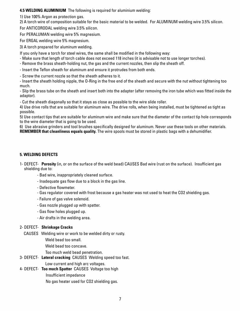
4.5 WELDING ALUMINIUM The following is required for aluminium welding: 1) Use 100% Argon as protection gas. 2) A torch wire of composition suitable for the basic material to be welded. For ALUMINUM welding wire 3.5% silicon. For ANTICORODAL welding wire 3.5% silicon. For PERALUMAN welding wire 5% magnesium. For ERGAL welding wire 5% magnesium. 3) A torch prepared for aluminum welding. If you only have a torch for steel wires, the same shall be modified in the following way: - Make sure that length of torch cable does not exceed 118 inches (it is advisable not to use longer torches). - Remove the brass sheath-holding nut, the gas and the current nozzles, then slip the sheath off. - Insert the Teflon sheath for aluminum and ensure it protrudes from both ends. - Screw the current nozzle so that the sheath adheres to it. - Insert the sheath holding nipple, the O-Ring in the free end of the sheath and secure with the nut without tightening too much. - Slip the brass tube on the sheath and insert both into the adapter (after removing the iron tube which was fitted inside the adaptor). - Cut the sheath diagonally so that it stays as close as possible to the wire slide roller. 4) Use drive rolls that are suitable for aluminum wire. The drive rolls, when being installed, must be tightened as tight as possible. 5) Use contact tips that are suitable for aluminum wire and make sure that the diameter of the contact tip hole corresponds to the wire diameter that is going to be used. 6) Use abrasive grinders and tool brushes specifically designed for aluminum. Never use these tools on other materials. REMEMBER that cleanliness equals quality. The wire spools must be stored in plastic bags with a dehumidifier.
5. WELDING DEFECTS
1- DEFECT- Porosity (in, or on the surface of the weld bead) CAUSES Bad wire (rust on the surface). Insufficient gas shielding due to:
- Bad wire, inappropriately cleaned surface.- Inadequate gas flow due to a block in the gas line. - Defective flowmeter. - Gas regulator covered with frost because a gas heater was not used to heat the CO2 shielding gas. - Failure of gas valve solenoid. - Gas nozzle plugged up with spatter. - Gas flow holes plugged up. - Air drafts in the welding area.
2- DEFECT- Shrinkage Cracks CAUSES Welding wire or work to be welded dirty or rusty.
Weld bead too small. Weld bead too concave. Too much weld bead penetration.
3- DEFECT- Lateral cracking CAUSES Welding speed too fast. Low current and high arc voltages.
4- DEFECT- Too much Spatter CAUSES Voltage too high Insufficient impedance No gas heater used for CO2 shielding gas.
8
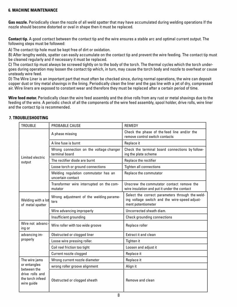
6. MACHINE MAINTENANCE
Gas nozzle. Periodically clean the nozzle of all weld spatter that may have accumulated during welding operations If the nozzle should become distorted or oval in shape then it must be replaced.
Contact tip. A good contact between the contact tip and the wire ensures a stable arc and optimal current output. The following steps must be followed: A) The contact tip hole must be kept free of dirt or oxidation. B) After lengthy welds, spatter can easily accumulate on the contact tip and prevent the wire feeding. The contact tip must be cleaned regularly and if necessary it must be replaced. C) The contact tip must always be screwed tightly on to the body of the torch. The thermal cycles which the torch under-goes during operation may loosen the contact tip which, in turn, may cause the torch body and nozzle to overheat or cause unsteady wire feed. D) The Wire Liner is an important part that must often be checked since, during normal operations, the wire can deposit copper dust or tiny metal shavings in the lining. Periodically clean the liner and the gas line with a jet of dry, compressed air. Wire liners are exposed to constant wear and therefore they must be replaced after a certain period of time.
Wire feed motor. Periodically clean the wire feed assembly and the drive rolls from any rust or metal shavings due to the feeding of the wire. A periodic check of all the components of the wire feed assembly, spool holder, drive rolls, wire liner and the contact tip is recommended.
7. TROUBLESHOOTING
Welding with a lot of metal spatter
Wrong adjustment of the welding parame-ters
Select the correct parameters through the weld-ing voltage switch and the wire-speed adjust-ment potentiometer
Wire advancing improperly Uncorrected sheath diam.
Insufficient grounding Check grounding connections
Wire not advanc-ing or
Wire roller with too wide groove Replace roller
advancing im-properly
Obstructed or clogged liner Extract it and clean
Loose wire pressing roller. Tighten it
Coil reel friction too tight Loosen and adjust it
Current nozzle clogged Replace it
The wire jams or entangles between the drive rolls and the torch infeed wire guide
Wrong current nozzle diameter Replace it
wrong roller groove alignment Align it
Obstructed or clogged sheath Remove and clean
TROUBLE PROBABLE CAUSE REMEDY
Limited electric output
A phase missing Check the phase of the feed line and/or the remove control switch contacts
A line fuse is burnt Replace it
Wrong connection on the voltage changer terminal board
Check the terminal board connections by follow-ing the plate scheme
The rectifier diode are burnt Replace the rectifier
Loose torch or ground connections Tighten all connections
Welding regulation commutator has an uncertain contact
Replace the commutator
Transformer wire interrupted on the com-mutator
Unscrew the commutator contact remove the wire insulation and put it under the contact
9
Note: All repair work must be done by qualified personnel.
Disconnect the power input cable from the mains supply before replacing cables or before removing the unit covers. The machine is equipped with a thermostat that shuts the machine down when the power source overheats. After the thermo-stat trips, let the power source cool down for several minutes before resuming welding operations. The troubleshooting table lists troubles, causes and remedies for those troubles that occur most commonly.
8. WELDING MACHINE SERVICING
Experience has shown that many fatal accidents originated from servicing improperly executed. For this reason, a careful and thorough inspection on a serviced welding machine is just as important as one carried out on a new welding machine. Furthermore, in this way producers can be protected from being held responsible for defects stemming from repairs not carried out by the manufacturer.
8.1 Prescriptions to follow for servicingAfter rewinding the transformer or the inductance, the welding machine must pass the applied-voltage test in accordance with indications of the international standard. If the servicing is not done by the manufacturers, the repaired welding machines which underwent replacements or modi-fications of any component shall be marked in a way such that the identity of the person having serviced it is clear. After making repairs, take care to re-order the cables so that there is sure to be insulation between the primary and secondary sides of the machine. Make sure that the wires cannot come into contact with moving parts or parts that heat during operation. Replace all clamps in their original positions on the machine, to prevent a connection between the prima-ry and secondary circuits if a conductor accidentally breaks or disconnects.
10
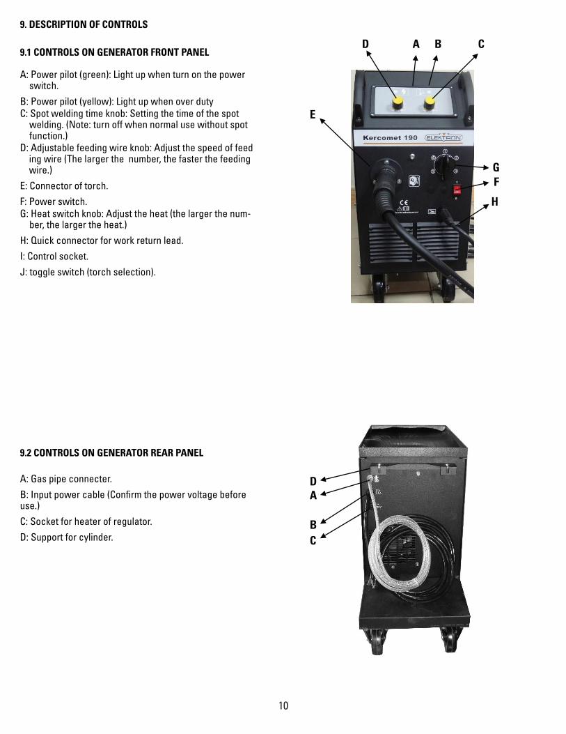
9. DESCRIPTION OF CONTROLS
9.1 CONTROLS ON GENERATOR FRONT PANEL
A: Power pilot (green): Light up when turn on the power switch.
B: Power pilot (yellow): Light up when over duty C: Spot welding time knob: Setting the time of the spot
welding. (Note: turn off when normal use without spot function.)
D: Adjustable feeding wire knob: Adjust the speed of feed ing wire (The larger the number, the faster the feeding wire.) E: Connector of torch.F: Power switch.G: Heat switch knob: Adjust the heat (the larger the num-
ber, the larger the heat.) H: Quick connector for work return lead.I: Control socket.J: toggle switch (torch selection).
9.2 CONTROLS ON GENERATOR REAR PANEL
A: Gas pipe connecter.B: Input power cable (Confirm the power voltage before use.) C: Socket for heater of regulator. D: Support for cylinder.
E
D A B C
G F
H
D A
B C
11
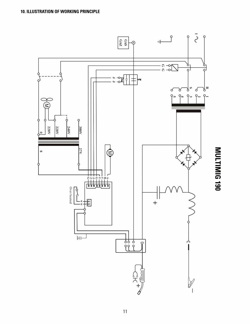
10. ILLUSTRATION OF WORKING PRINCIPLE
MU
LTIMIG
190
12
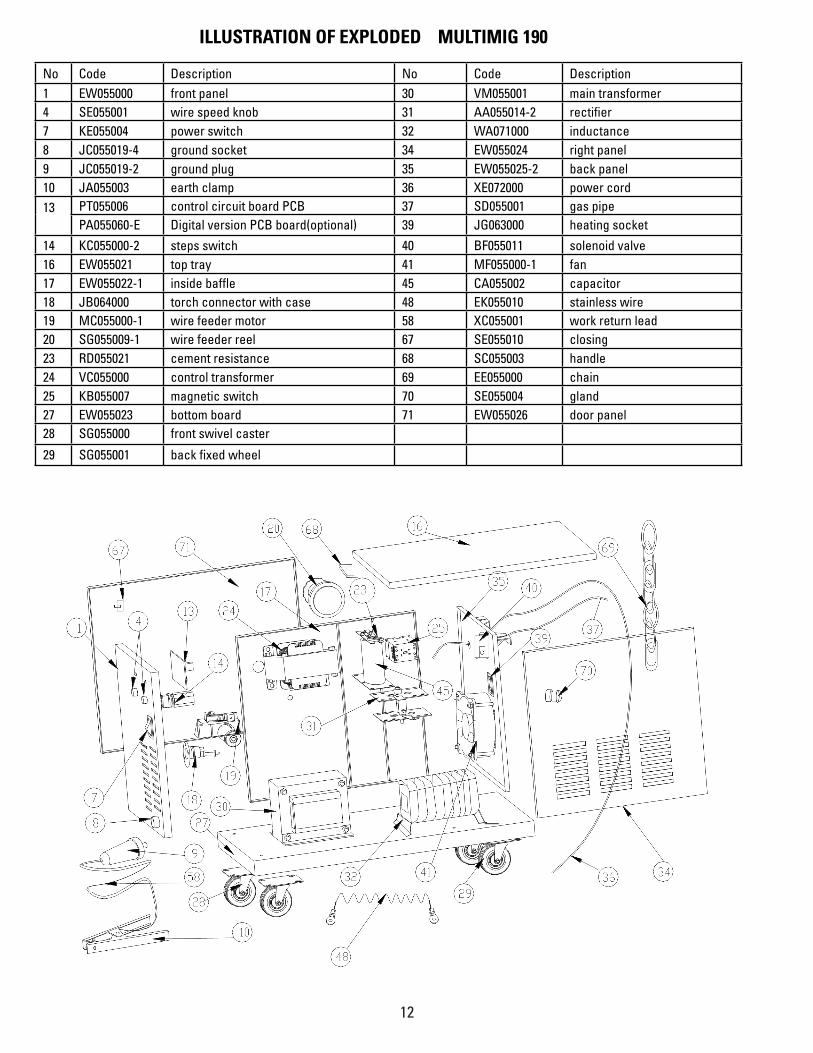
ILLUSTRATION OF EXPLODED MULTIMIG 190
No Code Description No Code Description 1 EW055000 front panel 30 VM055001 main transformer 4 SE055001 wire speed knob 31 AA055014-2 rectifier 7 KE055004 power switch 32 WA071000 inductance 8 JC055019-4 ground socket 34 EW055024 right panel 9 JC055019-2 ground plug 35 EW055025-2 back panel 10 JA055003 earth clamp 36 XE072000 power cord 13 PT055006 control circuit board PCB 37 SD055001 gas pipe
PA055060-E Digital version PCB board(optional) 39 JG063000 heating socket
14 KC055000-2 steps switch 40 BF055011 solenoid valve 16 EW055021 top tray 41 MF055000-1 fan 17 EW055022-1 inside baffle 45 CA055002 capacitor 18 JB064000 torch connector with case 48 EK055010 stainless wire 19 MC055000-1 wire feeder motor 58 XC055001 work return lead 20 SG055009-1 wire feeder reel 67 SE055010 closing 23 RD055021 cement resistance 68 SC055003 handle 24 VC055000 control transformer 69 EE055000 chain 25 KB055007 magnetic switch 70 SE055004 gland 27 EW055023 bottom board 71 EW055026 door panel 28 SG055000 front swivel caster 29 SG055001 back fixed wheel

13
Notes

14
Notes

15
Notes

996 Industrial Dr.Madison, IN 47250
Phone: 800.445.9262Fax: 866.275.0173
www.chiefautomotive.com
Chief reserves the right to alter product specifications and/or package components without notice.