Embed Size (px)
Citation preview
AT65 MULTIMEDIA SYSTEMS DECEMBER 2012
© IETE 1
Q2. a) What are the various media elements that are normally incorporated in multimedia presentation? Give examples how information may be conveyed through each of these media elements. Ans: (i) Text Inclusion of textual information in multimedia is the basic step towards development of multimedia software. Text can be of any type, may be a word, a single line, or a paragraph. The textual data for multimedia can be developed using any text editor. However to give special effects, one needs graphics software which supports this kind of job. Even one can use any of the most popular word processing software to create textual data for inclusion in multimedia. The text can have different type, size, color and style to suit the professional requirement of the multimedia software. (ii) Graphics Another interesting element in multimedia is graphics. As a matter of fact, taking into consideration the human nature, a subject is more explained with some sort of pictorial/graphical representation, rather than as a large chunk of text. This also helps to develop a clean multimedia screen, whereas use of large amount of text in a screen make it dull in presentation. Unlike text, which uses a universal ASCII format, graphics does not have a single agreed format. They have different format to suit different requirement. Most commonly used format for graphics is .BMP or bitmap pictures. The size of a graphics depends on the resolution it is using. A computer image uses pixel or dots on the screen to form itself. And these dots or pixel, when combined with number of colors and other aspects are called resolution. Resolution of an image or graphics is basically the pixel density and number of colors it uses. And the size of the image depends on its resolution. A standard VGA (Virtual Graphics Arrays) screen can display a screen resolution of 640 ´ 480 = 307200 pixel. And a Super VGA screen can display up-to 1024 ´ 768 = 786432 pixel on the screen. While developing multimedia graphics one should always keep in mind the image resolution and number of colors to be used, as this has a direct relation with the image size. If the image size is bigger, it takes more time to load and also requires higher memory for processing and larger disk-space for storage.However, different graphics formats are available which take less space and are faster to load into the memory.There are several graphics packages available to develop excellent images and also to compress them so that they take lesser disk-space but use higher resolution and more colours. Packages like Adobe PhotoShop, Adobe Illustrator, PaintShop Pro etc. are excellent graphics packages. There are Graphics gallery available in CD’s (Compact Disk) with readymade images to suit almost every requirement. These images can directly be incorporated into multimedia development. (iii) Animation Moving images have an overpowering effect on the human peripheral vision. Followings are few points for its popularity. Showing continuity in transitions:
AT65 MULTIMEDIA SYSTEMS DECEMBER 2012
© IETE 2
Animation is a set of static state, related to each other with transition. When something has two or more states, then changes between states will be much easier for users to understand if the transitions are animated instead of being instantaneous. An animated transition allows the user to track the mapping between different subparts through the perceptual system instead of having to involve the cognitive system to deduce the mappings. Indicating dimensionality in transitions:Sometimes opposite animated transitions can be used to indicate movement back and forth along some navigational dimension. One example used in several user interfaces is the use of zooming to indicate that a new object is "grown" from a previous one (e.g., a detailed view or property list opened by clicking on an icon) or that an object is closed or minimized to a smaller representation. Zooming out from the small object to the enlargement is a navigational dimension and zooming in again as the enlargement is closed down is the opposite direction along that dimension. Illustrating change over time Since animation is a time-varying display, it provides a one-to-one mapping to phenomena that change over time. For example, deforestation of the rain forest can be illustrated by showing a map with an animation of the covered area changing over time. Multiplexing the display Animation can be used to show multiple information objects in the same space. A typical example is client-side image maps with explanations that pop up as the user moves the cursor over the various hypertext anchors. Enriching graphical representations: Some types of information are easier to visualize with movement than with still pictures. Consider, for example, how to visualize the tool used to remove pixels in a graphics application. Video Beside animation there is one more media element, which is known as video. With latest technology it is possible to include video impact on clips of any type into any multimedia creation, be it corporate presentation, fashion design, entertainment games, etc. The video clips may contain some dialogues or sound effects and moving pictures. These video clips can be combined with the audio, text and graphics for multimedia presentation. Incorporation of video in a multimedia package is more important and complicated than other media elements. One can procure video clips from various sources such as existing video films or even can go for an outdoor video shooting. All the video available are in analog format. To make it usable by computer, the video clips are needed to be converted into computer understandable format, i.e., digital format. Both combinations of software and hardware make it possible to convert the analog video clips into digital format. This alone does not help, as the digitised video clips take lots of hard disk space to store, depending on the frame rate used for digitisation. The computer reads a particular video clip as a series of still pictures called frames. Thus video clip is made of a series of separate frames where each frame is slightly different from the previous one. The computer reads each frame as a bitmap image. Generally there are 15 to 25 frames per second so that the movement is smooth. If we take less frames than this, the movement of the images will not be smooth. To cut down the space there are several modern technologies in windows environment. Essentially these technologies compress the video image so that lesser space is required.

AT65 MULTIMEDIA SYSTEMS DECEMBER 2012
© IETE 3
However, latest video compression software makes it possible to compress the digitised video clips to its maximum. In the process, it takes lesser storage space. One more advantage of using digital video is, the quality of video will not deteriorate from copy to copy as the digital video signal is made up of digital code and not electrical signal. Caution should be taken while digitizing the video from analog source to avoid frame droppings and distortion. A good quality video source should be used for digitization. Currently, video is good for: promoting television shows, films, or other non-computer media that traditionally have used trailers in their advertising. giving users an impression of a speaker’s personality. showing things that move. For example a clip from a motion picture. Product demos of physical products are also well suited for video. Audio Audio has a greater role to play in multimedia development. It gives life to the static state of multimedia. Incorporation of audio is one of the most important features of multimedia, which enhance the multimedia usability to its full potential. There are several types of sound, which can be used in multimedia. They are human voices, instrumental notes, natural sound and many more. All these can be used in any combination as long as they give some meaning to their inclusion in multimedia. There are many ways in which these sounds can be incorporated into the computer. For example; Using microphone, human voice can directly be recorded in a computer. Pre-recorded cassettes can be used to record the sound into computer. Instrumental sound can also be played directly from a musical instrument for recording into the computer. The sound transmitted from these sources is of analog nature. To enable the computer to process this sound, they need to be digitised. As all of us know that sound is a repeated pattern of pressure in the air and a microphone converts a sound wave into an electrical wave. The clarity of sound, the final output depends entirely on the shape and frequency of the sound wave. When digitised (recording into computer), the error in sound can be drastically reduced. Audio need to be converted into digital format to produce digitised audio in order to use them in multimedia. And these digitised sounds again can be re-converted into analog form so that the user can hear them though the speakers. Musical Instrument Digitisation Interface or MIDI provides a protocol or a set of rules, using which the details of a musical note from an instrument is communicated to the computer. But MIDI data is not digitized sound. It is directly recorded into the computer from musical instruments, whereas digitised audio is created from the analog sound. The quality of MIDI data depends upon the quality of musical instrument and the sound system. A MIDI file is basically a list command to produce the sound. For example, pressing of a guitar key can be represented as a computer command. When the MIDI device processes this command, the result will be the sound from the guitar. MIDI files occupy lesser space as compared to the digitised audio and they are editable also. The main benefit of audio is that it provides an exclusive channel that is separate from that of the display. Speech can be used to offer commentary or help without obscuring information on the screen. Audio can also be used to provide a sense of place or mood. Mood-setting audio should employ very quiet background sounds in order not to compete with the main information for the
AT65 MULTIMEDIA SYSTEMS DECEMBER 2012
© IETE 4
user’s attention. Music is probably the most obvious use of sound. Whenever you need to inform the user about a certain work of music, it makes much more sense to simply play it than to show the notes or to try to describe it in words. b) What are the various types of software used for implementing a multimedia production? Also differentiate between GIF and JPEG file formats Ans: Multimedia is created and displayed using a range of software applications, including: authoring software, presentation software, html editors I. Authoring software Also known as authorware, a program that helps you write hypertext or multimedia applications. Authoring tools usually enable you to create a final application merely by linking together objects, such as a paragraph of text, an illustration, or a song. By defining the objects' relationships to each other, and by sequencing them in an appropriate order, authors (those who use authoring tools) can produce attractive and useful graphics applications. Most authoring systems also support a scripting language for more sophisticated applications. The distinction between authoring tools and programming tools is not clear-cut. Typically, though, authoring tools require less technical knowledge to master and are used exclusively for applications that present a mixture of textual, graphical, and audio data. II. Presentation software A presentation program (also called a presentation graphics program) is a computer software package used to display information, normally in the form of a slide show. It typically includes three major functions: an editor that allows text to be inserted and formatted, a method for inserting and manipulating graphic images and a slide-show system to display the content. Many presentation programs come with pre-designed images (clip art) and/or have the ability to import graphic images. Custom graphics can also be created in other programs such as Adobe Photoshop or Adobe Illustrator and then exported. With the growth of digital photography and video, many programs that handle these types of media also include presentation functions for displaying them in a similar "slide show" format. For example, Apple's iPhoto allows groups of digital photos to be displayed in a slide show with options such as selecting transitions, choosing whether or not the show stops at the end or continues to loop, and including music to accompany the photos. Similar to programming extensions for an operating system or web browser, "add ons" or plugins for presentation programs can be used to enhance their capabilities. For example, it would be useful to export a PowerPoint presentation as a Flash animation or PDF document. This would make delivery through removable media or sharing over the Internet easier. Since PDF files are designed to be shared regardless of platform and most web browsers already have the plugin to view Flash files, these formats would allow presentations to be more widely accessible. Certain presentation programs also offer an interactive integrated hardware element designed to engage an audience (e.g. audience response systems) or facilitate presentations across different geographical locations (e.g. web conferencing). Other integrated hardware devices ease the job of a live presenter such as laser pointers and interactive whiteboards.
AT65 MULTIMEDIA SYSTEMS DECEMBER 2012
© IETE 5
III. Html Editors: An HTML editor is a software application for creating web pages. Although the HTML markup of a web page can be written with any text editor, specialized HTML editors can offer convenience and added functionality. For example, many HTML editors work not only with HTML, but also with related technologies such as CSS, XML and JavaScript or ECMAScript. In some cases they also manage communication with remote web servers via FTP and WebDAV, and version management systems such as CVS or Subversion. There are various forms of HTML editors: text, object and WYSIWYG (What You See Is What You Get) editors. The GIF Format The GIF format is one of the most popular formats on the Internet. Not only is the format excellent at compressing areas of images with large areas of the same color, but it is also the only option for putting animation online (unless you want to use Flash or other vector-based animation formats, which typically cost more). The GIF89a format also supports transparency, and interlacing. GIF files support a maximum of 256 colors, which makes them practical for almost all graphics except photographs. The most common method of reducing the size of GIF files is to reduce the number of colors on the palette. It is important to note that GIF already uses the LZW compression scheme internally to make images as small as possible without losing any data. Transparency As I mentioned above, the GIF format supports transparency. This allows a graphic designer to designate the background of the image transparent. This means that if you place a transparent GIF in a yellow table cell, the background color of that image will turn yellow. Interlacing The interlacing feature in a GIF file creates the illusion of faster loading graphics. What happens is that an image is presented in a browser in several steps. At first it will be fuzzy and blurry, but as more information is downloaded from the server, the image becomes more and more defined until the entire image has been downloaded. It’s important to note that interlaced GIF files will usually be a bit larger than non-interlaced ones, so use interlacing only when it makes sense. When to use them Generally, GIF files should be used for logos, line drawings and icons. Avoid using it for photographic images, and graphics which have long stretches of continuous-tone in them. When you’re designing GIF files, avoid using gradients and turn off anti-aliasing where possible to minimize the file size. The JPEG Format The JPEG format, with its support for 16.7 million colors, is primarily intended for photographic images. The internal compression algorithm of the JPEG format, unlike the GIF format, actually throws out information. Depending on what settings you use, the thrown out data may or may not be visible to the eye. Once you lower the quality of an image, and save it, the extra data cannot be regained so be sure to save the original.

AT65 MULTIMEDIA SYSTEMS DECEMBER 2012
© IETE 6
Progressive JPEG’s Any JPEG file can be saved as a Progressive JPEG. This is very similar to the interlaced GIF. As with GIF, this presents a low-quality image to your visitor at first, and over several passes improves the quality of it. Some graphic editing tools allow you to specify the number of passes before the image downloads completely. When to use As a rule, the JPEG format should be used on photographic images, and images which do not look as good with only 256 colors. Q2 c) Explain Macromedia Flash and VRML multimedia authoring tools. Ans: Adobe Flash (formerly Macromedia Flash) is a multimedia platform used to add animation, video, and interactivity to web pages. Flash is frequently used for advertisements, games and flash animations for broadcast. More recently, it has been positioned as a tool for "Rich Internet Applications" ("RIAs"). Flash manipulates vector and raster graphics to provide animation of text, drawings, and still images. It supports bidirectional streaming of audio and video, and it can capture user input via mouse, keyboard, microphone, and camera. Flash contains an object-oriented language called ActionScript and supports automation via the Javascript Flash language (JFSL). Flash content may be displayed on various computer systems and devices, using Adobe Flash Player, which is available free of charge for common web browsers, some mobile phones and a few other electronic devices. Some users feel that Flash enriches their web experience, while others find the extensive use of Flash animation, particularly in advertising, intrusive and annoying, giving rise to a cottage industry that specializes in blocking Flash content. Flash has also been criticized for adversely affecting the usability of web pages. Flash as a format has become widespread on the desktop market; one estimate is that 95% of PCs have it, while Adobe claims that 98 percent of U.S. web users and 99.3 percent of all Internet desktop users have installed the Flash Player with 92 to 95% (depending on region) having the latest version. Numbers vary depending on the detection scheme and research demographics. The Adobe Flash Player exists for a variety of systems and devices: Windows, Mac OS 9/X, Linux, Solaris, HP-UX, Pocket PC/Windows CE, OS/2, QNX, Android, Symbian, Palm OS, BeOS, and IRIX, although the performance is typically best on Windows (see Performance). For compatibility with devices (embedded systems), see Macromedia Flash Lite. Some websites rely on Flash so heavily that they are totally unusable without this plugin Among mobile devices, Flash has less penetration because Apple does not bundle or allow third-party runtimes on its iPhone, which accounts for more than 60% of global smartphone web traffic, or the iPod touch, which makes up more than 95% of "mobile Internet device" traffic. This hurts Adobe's ability to market Flash as a ubiquitous mobile platform. However, Flash is enabled on competing mobile platforms, including the version 2.2 Android while other O.S.s such as Symbian and Palm have versions coming.[citation needed]. On Mar 8, 2011, Techradar reported that Adobe
AT65 MULTIMEDIA SYSTEMS DECEMBER 2012
© IETE 7
provides an experimental server side tool (Wallaby) to convert Flash programs (as far as possible) to HTML5 code, thus allowing iOS devices to display the content. Downloading Flash is blocked in countries that are under U.S sanctions (such as Syria & Sudan). Users in these countries are blocked (by Adobe) from downloading Flash plug-ins for both Internet Explorer and Firefox browsers. Flash content is usually embedded using the object HTML element, or the nonstandard embed element. Software that does not support either of these elements, and users who cannot or will not install a plugin, will see the replacement text if this is supplied by the web page. Q3. a.) How does a CMYK color model represent color information? Why is it called a subtractive model? Ans: The CMYK Color Model The CMYK model defines color using Cyan (C), Magenta (M), Yellow (Y) and Black (K) inks or pigments. Each color contains an amount of ink that is measured with a percent from 0 to 100. A value of 100 means that the inks is applied at full saturation. The CMYK color model is a Subtractive Color Model. Subtractive color uses reflected light to display color. Printed materials are produced using the CMYK color model. The combination of the amounts of cyan, magenta, yellow, and black ink defines the resulting CMYK color. When you combine cyan, magenta, yellow, and black ink together and each component has a value of 100, then the resulting color, in theory, should be black. When the value of each component is 0, the resulting color is pure white. With the CMYK subtractive model, in theory, you should be able to product millions of colors, but due to the limitations of printing inks and the printing process you can only produce thousands of colors in print. Computers can display millions of CMYK colors, although they can't all be reproduced on a printer. b) What is meant by Chroma subsampling? Explain how does it help in bandwidth reductions. Ans: Chroma subsampling is the practice of encoding images by implementing less resolution for chroma information than for luma information, taking advantage of the human visual system's lower acuity for color differences than for luminance. It is used in many video encoding schemes — both analog and digital — and also in JPEG encoding. Because the human visual system is less sensitive to the position and motion of color than luminance,bandwidth can be optimized by storing more luminance detail than color detail. At normal viewing distances, there is no perceptible loss incurred by sampling the color detail at a lower rate. In video systems, this is achieved through the use of color difference components. The signal is divided into a luma (Y') component and two color difference components (chroma). Chroma subsampling deviates from color science in that the luma and chroma components are formed as a weighted sum of gamma-corrected (tristimulus) R'G'B' components instead of linear

AT65 MULTIMEDIA SYSTEMS DECEMBER 2012
© IETE 8
(tristimulus) RGB components. As a result, luminance and color detail are not completely independent of one another. There is some "bleeding" of luminance and color information between the luma and chroma components. The error is greatest for highly-saturated colors and can be somewhat noticeable in between the magenta and green bars of a color bars test pattern (that has chroma subsampling applied). This engineering approximation (by reversing the order of operations between gamma corrections and forming the weighted sum) allows color subsampling to be more easily implemented. The subsampling scheme is commonly expressed as a three part ratio J:a:b (e.g. 4:2:2), although sometimes expressed as four parts (e.g. 4:2:2:4), that describe the number of luminance and chrominance samples in a conceptual region that is J pixels wide, and 2 pixels high. The parts are (in their respective order): J: horizontal sampling reference (width of the conceptual region). Usually, 4. a: number of chrominance samples (Cr, Cb) in the first row of J pixels. b: number of (additional) chrominance samples (Cr, Cb) in the second row of J pixels. Alpha: horizontal factor (relative to first digit). May be omitted if alpha component is not present, and is equal to J when present. Q4.a) With the help of a diagram show how MIDI instruments can be interfaced with a PC. Ans. The basic principle is simple -perhaps even brilliant. Every function on a MIDI instrument is assigned a numeric value. When the MIDI Specification was first developed, the unique numbering system it was based upon enabled it to communicate quite nicely with a computer. Computers, of course, are essentially numeric processors. It’s because of this numerical common ground that a MIDI instrument is naturally suited for interfacing with a computer. When you play a MIDI instrument you hear music. On the other hand, if you connect the instrument to a computer, the computer is “hearing” and recording only the MIDI numbers, not any sound whatsoever. As a matter of fact, you are actually just speed-typing a series of numbers whenever you play your MIDI instrument! I repeat, when you record a MIDI performance, the computer software is capturing only MIDI numbers -no actual sound is being recorded. When you playback a MIDI performance, these numbers are transmitted to your MIDI instrument (or soundcard) and these MIDI numbers “trigger” the sounds that are already built into the instrument. When the built-in sounds are triggered, you hear the playback through the speakers the instrument or soundcard is connected to. Each note you play on a MIDI instrument has a specific number assigned to it. For instance, if I am using notation software and I play a middle C on the keyboard, the computer recognizes this note as NOTE #60, but I will see the note displayed as standard notation on the computer screen, and I will hear the middle C “triggered” via the attached instrument or soundcard. If I want the computer to change this note one full step up, a +1 number will be added for each half-step interval. In this example, the computer would see the result of this transposition as NOTE #62. It’s not only just the notes that have numbers assigned to them. There is a lot more going on than simply entering the notes themselves when you play your MIDI instrument. Each built-in sound on your MIDI keyboard has an INSTRUMENT NUMBER assignment. You select the sound you want by pressing a button on the instrument or by manually entering the instrument number in the appropriate location in your music software. The number assigned to that sound is recorded and
AT65 MULTIMEDIA SYSTEMS DECEMBER 2012
© IETE 9
saved by the computer, then the MIDI Instrument Number is transmitted back to your instrument during playback in order to permit the note numbers trigger the specific sound you selected. When you use a sustain pedal, change volume, play expressively (harder or softer), the computer is receiving what are known as MIDI CONTROLLER NUMBERS. When you record MIDI performances, your music software also keeps track of when you play the notes (timing), how fast you are playing (tempo), and how long you hold each note (duration). Again, it can do this because there are specific MIDI numbers assigned to all these events and more. As you play the keyboard, a stream of MIDI numbers are sent in a continuous flow to the computer. Once this information is recorded by your computer music software, the full benefits of MIDI can be realized b) Differentiate between DPCM and ADPCM with an example. Ans. DPCM: Stores a multibit difference value. A bipolar D/A converter is used for playback to convert the successive difference values to an analog waveform. ADPCM: Stores a difference value that has been mathematically adjusted according to the slope of the input waveform. Bipolar D/A converter is used to convert the stored digital code to analog for playback. Example to be based on the above stated difference. c) With the help of a suitable example, perform Huffman encoding & decoding and explain. Ans: Huffman coding uses a specific method for choosing the representation for each symbol, resulting in a prefix code (sometimes called "prefix-free codes", that is, the bit string representing some particular symbol is never a prefix of the bit string representing any other symbol) that expresses the most common source symbols using shorter strings of bits than are used for less common source symbols. Huffman was able to design the most efficient compression method of this type: no other mapping of individual source symbols to unique strings of bits will produce a smaller average output size when the actual symbol frequencies agree with those used to create the code. A method was later found to design a Huffman code in linear time if input probabilities (also known as weights) are sorted. For a set of symbols with a uniform probability distribution and a number of members which is a power of two, Huffman coding is equivalent to simple binary block encoding, e.g., ASCII coding. Huffman coding is such a widespread method for creating prefix codes that the term "Huffman code" is widely used as a synonym for "prefix code" even when such a code is not produced by Huffman's algorithm. Although Huffman's original algorithm is optimal for a symbol-by-symbol coding (i.e. a stream of unrelated symbols) with a known input probability distribution, it is not optimal when the symbol-by-symbol restriction is dropped, or when the probability mass functions are unknown, not identically distributed, or not independent (e.g., "cat" is more common than "cta"). Other methods such as arithmetic coding and LZW coding often have better compression capability: both of these methods can combine an arbitrary number of symbols for more efficient coding, and generally adapt to the actual input statistics, the latter of which is useful when input probabilities are not precisely known or vary significantly within the stream. However, the limitations of Huffman coding should not be overstated; it can be used adaptively, accommodating unknown, changing, or context-
AT65 MULTIMEDIA SYSTEMS DECEMBER 2012
© IETE 10
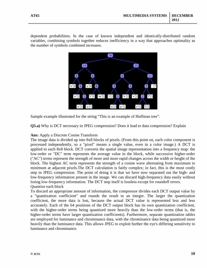
dependent probabilities. In the case of known independent and identically-distributed random variables, combining symbols together reduces inefficiency in a way that approaches optimality as the number of symbols combined increases.
Sample example illustrated for the string “This is an example of Huffman tree”. Q5.a) Why is DCT necessary in JPEG compression? Does it lead to data compression? Explain Ans: Apply a Discrete Cosine Transform The image data is divided up into 8x8 blocks of pixels. (From this point on, each color component is processed independently, so a "pixel" means a single value, even in a color image.) A DCT is applied to each 8x8 block. DCT converts the spatial image representation into a frequency map: the low-order or "DC" term represents the average value in the block, while successive higher-order ("AC") terms represent the strength of more and more rapid changes across the width or height of the block. The highest AC term represents the strength of a cosine wave alternating from maximum to minimum at adjacent pixels.The DCT calculation is fairly complex; in fact, this is the most costly step in JPEG compression. The point of doing it is that we have now separated out the high- and low-frequency information present in the image. We can discard high-frequency data easily without losing low-frequency information. The DCT step itself is lossless except for roundoff errors. Quantize each block To discard an appropriate amount of information, the compressor divides each DCT output value by a "quantization coefficient" and rounds the result to an integer. The larger the quantization coefficient, the more data is lost, because the actual DCT value is represented less and less accurately. Each of the 64 positions of the DCT output block has its own quantization coefficient, with the higher-order terms being quantized more heavily than the low-order terms (that is, the higher-order terms have larger quantization coefficients). Furthermore, separate quantization tables are employed for luminance and chrominance data, with the chrominance data being quantized more heavily than the luminance data. This allows JPEG to exploit further the eye's differing sensitivity to luminance and chrominance.
AT65 MULTIMEDIA SYSTEMS DECEMBER 2012
© IETE 11
It is this step that is controlled by the "quality" setting of most JPEG compressors. The compressor starts from a built-in table that is appropriate for a medium-quality setting and increases or decreases the value of each table entry in inverse proportion to the requested quality. The complete quantization tables actually used are recorded in the compressed file so that the decompressor will know how to (approximately) reconstruct the DCT coefficients. Selection of an appropriate quantization table is something of a black art. Most existing compressors start from a sample table developed by the ISO JPEG committee. It is likely that future research will yield better tables that provide more compression for the same perceived image quality. Implementation of improved tables should not cause any compatibility problems, because decompressors merely read the tables from the compressed file; they don't care how the table was picked. Encode the resulting coefficients The resulting coefficients contain a significant amount of redundant data. Huffman compression will losslessly remove the redundancies, resulting in smaller JPEG data. b) Give a short note on Wavelet Based Coding and Inverse DCT. Ans: Inverse DCT: the inverse of DCT-I is DCT-I multiplied by 2/(N-1). The inverse of DCT-IV is DCT-IV multiplied by 2/N. The inverse of DCT-II is DCT-III multiplied by 2/N and vice versa. Like for the DFT, the normalization factor in front of these transform definitions is merely a convention and differs between treatments. For example, some authors multiply the transforms by \sqrt{2/N} so that the inverse does not require any additional multiplicative factor. Combined with appropriate factors of √2 (see above), this can be used to make the transform matrix orthogonal. Wavelet Based Coding Wavelet compression is a form of data compression well suited for image compression (sometimes also video compression and audio compression). Notable implementations are JPEG 2000 and ECW for still images, and REDCODE, the BBC's Dirac, and Ogg Tarkin for video. The goal is to store image data in as little space as possible in a file. Wavelet compression can be either lossless or lossy. Using a wavelet transform, the wavelet compression methods are adequate for representing transients, such as percussion sounds in audio, or high-frequency components in two-dimensional images, for example an image of stars on a night sky. This means that the transient elements of a data signal can be represented by a smaller amount of information than would be the case if some other transform, such as the more widespread discrete cosine transform, had been used. Wavelet compression is not good for all kinds of data: transient signal characteristics mean good wavelet compression, while smooth, periodic signals are better compressed by other methods, particularly traditional harmonic compression (frequency domain, as by Fourier transforms and related). Data statistically indistinguishable from random noise is not compressible by any means.
AT65 MULTIMEDIA SYSTEMS DECEMBER 2012
© IETE 12
Q6a) Explain various steps involved in H.261 standard. Give a brief note on H.263+ Standard Ans: H.261 is a ITU-T video coding standard also known as MPEG-1, ratified in November 1988. It is the first member of the H.26x family of video coding standards in the domain of the ITU-T Video Coding Experts Group (VCEG), and was the first video codec that was useful in practical terms. H.261 was originally designed for transmission over ISDN lines on which data rates are multiples of 64 kbit/s. The coding algorithm was designed to be able to operate at video bit rates between 40 kbit/s and 2 Mbit/s. The standard supports two video frame sizes: CIF (352x288 luma with 176x144 chroma) and QCIF (176x144 with 88x72 chroma) using a 4:2:0 sampling scheme. It also has a backward-compatible trick for sending still picture graphics with 704x576 luma resolution and 352x288 chroma resolution The basic processing unit of the design is called a macroblock, and H.261 was the first standard in which the macroblock concept appeared. Each macroblock consists of a 16x16 array of luma samples and two corresponding 8x8 arrays of chroma samples, using 4:2:0 sampling and a YCbCr color space. The inter-picture prediction reduces temporal redundancy, with motion vectors used to help the codec compensate for motion. Whilst only integer-valued motion vectors are supported in H.261, a blurring filter can be applied to the prediction signal — partially mitigating the lack of fractional-sample motion vector precision. Transform coding using an 8x8 discrete cosine transform (DCT) reduces the spatial redundancy. Scalar quantization is then applied to round the transform coefficients to the appropriate precision determined by a step size control parameter, and the quantized transform coefficients are zig-zag scanned and entropy coded (using a "run-level" variable-length code) to remove statistical redundancy. The H.261 standard actually only specifies how to decode the video. Encoder designers were left free to design their own encoding algorithms, as long as their output was constrained properly to allow it to be decoded by any decoder made according to the standard. Encoders are also left free to perform any pre-processing they want to their input video, and decoders are allowed to perform any post-processing they want to their decoded video prior to display. One effective post-processing technique that became a key element of the best H.261-based systems is called deblocking filtering. This reduces the appearance of block-shaped artifacts caused by the block-based motion compensation and spatial transform parts of the design. Indeed, blocking artifacts are probably a familiar phenomenon to almost everyone who has watched digital video. Deblocking filtering has since become an integral part of the most recent standard, H.264 (although even when using H.264, additional post-processing is still allowed and can enhance visual quality if performed well). Design refinements introduced in later standardization efforts have resulted in significant improvements in compression capability relative to the H.261 design. This has resulted in H.261 becoming essentially obsolete, although it is still used as a backward-compatibility mode in some video conferencing systems and for some types of internet video. However, H.261 remains a major historical milestone in the development of the field of video coding.
AT65 MULTIMEDIA SYSTEMS DECEMBER 2012
© IETE 13
H.263 is a video compression standard originally designed as a low-bitrate compressed format for videoconferencing. It was developed by the ITU-T Video Coding Experts Group (VCEG) in a project ending in 1995/1996 as one member of the H.26x family of video coding standards in the domain of the ITU-T. H.263 has since found many applications on the internet: much Flash Video content (as used on sites such as YouTube, Google Video, MySpace, etc.) used to be encoded in Sorenson Spark format (an incomplete implementation of H.263), though many sites now use VP6 or H.264 encoding. The original version of the RealVideo codec was based on H.263 up until the release of RealVideo 8. H.263 is a required video codec in ETSI 3GPP technical specifications for IP Multimedia Subsystem (IMS), Multimedia Messaging Service (MMS) and Transparent end-to-end Packet-switched Streaming Service (PSS). In 3GPP specifications, H.263 video is usually used in 3GP container format. b) Explain various parts of the MPEG-1 standard. Describe the MPEG-1 video standard mentioning the roles of I-,P- and B- frames. Ans: Part 1: Systems Part 1 of the MPEG-1 standard covers systems, and is defined in ISO/IEC-11172-1. MPEG-1 Systems specifies the logical layout and methods used to store the encoded audio, video, and other data into a standard bitstream, and to maintain synchronization between the different contents. This file format is specifically designed for storage on media, and transmission over data channels, that are considered relatively reliable. Only limited error protection is defined by the standard, and small errors in the bitstream may cause noticeable defects. This structure was later named an MPEG program stream: "The MPEG-1 Systems design is essentially identical to the MPEG-2 Program Stream structure." Elementary streams Elementary Streams (ES) are the raw bitstreams of MPEG-1 audio and video encoded data (output from an encoder). These files can be distributed on their own, such as is the case with MP3 files. Packetized Elementary Streams (PES) are elementary streams packetized into packets of variable lengths, i.e., divided ES into independent chunks where cyclic redundancy check (CRC) checksum was added to each packet for error detection. System Clock Reference (SCR) is a timing value stored in a 33-bit header of each PES, at a frequency/precision of 90 kHz, with an extra 9-bit extension that stores additional timing data with a precision of 27 MHz. These are inserted by the encoder, derived from the system time clock (STC). Simultaneously encoded audio and video streams will not have identical SCR values, however, due to buffering, encoding, jitter, and other delay. Program streams Program Streams (PS) are concerned with combining multiple packetized elementary streams (usually just one audio and video PES) into a single stream, ensuring simultaneous delivery, and maintaining synchronization. The PS structure is known as a multiplex, or a container format.
AT65 MULTIMEDIA SYSTEMS DECEMBER 2012
© IETE 14
Part 2: Video Part 2 of the MPEG-1 standard covers video and is defined in ISO/IEC-11172-2. The design was heavily influenced by H.261. MPEG-1 Video exploits perceptual compression methods to significantly reduce the data rate required by a video stream. It reduces or completely discards information in certain frequencies and areas of the picture that the human eye has limited ability to fully perceive. It also exploits temporal (over time) and spatial (across a picture) redundancy common in video to achieve better data compression than would be possible otherwise. Frame/picture/block types MPEG-1 has several frame/picture types that serve different purposes. The most important, yet simplest, is I-frame. I-frames I-frame is an abbreviation for Intra-frame, so-called because they can be decoded independently of any other frames. They may also be known as I-pictures, or keyframes due to their somewhat similar function to the key frames used in animation. I-frames can be considered effectively identical to baseline JPEG images. High-speed seeking through an MPEG-1 video is only possible to the nearest I-frame. When cutting a video it is not possible to start playback of a segment of video before the first I-frame in the segment (at least not without computationally intensive re-encoding). For this reason, I-frame-only MPEG videos are used in editing applications. I-frame only compression is very fast, but produces very large file sizes: a factor of 3× (or more) larger than normally encoded MPEG-1 video, depending on how temporally complex a specific video is. I-frame only MPEG-1 video is very similar to MJPEG video. So much so that very high-speed and theoretically lossless (in reality, there are rounding errors) conversion can be made from one format to the other, provided a couple of restrictions (color space and quantization matrix) are followed in the creation of the bitstream. The length between I-frames is known as the group of pictures (GOP) size. MPEG-1 most commonly uses a GOP size of 15-18. i.e. 1 I-frame for every 14-17 non-I-frames (some combination of P- and B- frames). With more intelligent encoders, GOP size is dynamically chosen, up to some pre-selected maximum limit. Limits are placed on the maximum number of frames between I-frames due to decoding complexing, decoder buffer size, recovery time after data errors, seeking ability, and accumulation of IDCT errors in low-precision implementations most common in hardware decoders

AT65 MULTIMEDIA SYSTEMS DECEMBER 2012
© IETE 15
P-frames P-frame is an abbreviation for Predicted-frame. They may also be called forward-predicted frames, or inter-frames (B-frames are also inter-frames). P-frames exist to improve compression by exploiting the temporal (over time) redundancy in a video. P-frames store only the difference in image from the frame (either an I-frame or P-frame) immediately preceding it (this reference frame is also called the anchor frame). The difference between a P-frame and its anchor frame is calculated using motion vectors on each macroblock of the frame. Such motion vector data will be embedded in the P-frame for use by the decoder. A P-frame can contain any number of intra-coded blocks, in addition to any forward-predicted blocks. If a video drastically changes from one frame to the next (such as a cut), it is more efficient to encode it as an I-frame. B-frames B-frame stands for bidirectional-frame. They may also be known as backwards-predicted frames or B-pictures. B-frames are quite similar to P-frames, except they can make predictions using both the previous and future frames (i.e. two anchor frames). It is therefore necessary for the player to first decode the next I- or P- anchor frame sequentially after the B-frame, before the B-frame can be decoded and displayed. This means decoding B-frames requires larger data buffers and causes an increased delay on both decoding and during encoding. This also necessitates the decoding time stamps (DTS) feature in the container/system stream .As such, B-frames have long been subject of much controversy, and they are often avoided in videos, and are sometimes not fully supported by hardware decoders. No other frames are predicted from a B-frame. Because of this, a very low bitrate B-frame can be inserted, where needed, to help control the bitrate. If this was done with a P-frame, future P-frames would be predicted from it and would lower the quality of the entire sequence. However, similarly, the future P-frame must still encode all the changes between it and the previous I- or P- anchor frame. B-frames can also be beneficial in videos where the background behind an object is being revealed over several frames, or in fading transitions, such as scene changes. A B-frame can contain any number of intra-coded blocks and forward-predicted blocks, in addition to backwards-predicted, or bidirectionally predicted blocks.
AT65 MULTIMEDIA SYSTEMS DECEMBER 2012
© IETE 16
D-frames MPEG-1 has a unique frame type not found in later video standards. D-frames or DC-pictures are independent images (intra-frames) that have been encoded DC-only and hence are very low quality. D-frames are never referenced by I-, P- or B- frames. D-frames are only used for fast previews of video, for instance when seeking through a video at high speed. Given moderately higher-performance decoding equipment, this feature can be approximated by decoding I-frames instead. This provides higher quality previews, and without the need for D-frames taking up space in the stream, yet not improving video quality. Q7. a) Differentiate between Vocoders and ADPCM as audio compression techniques. Ans: The human voice consists of sounds generated by the opening and closing of the glottis by the vocal cords, which produces a periodic waveform with many harmonics. This basic sound is then filtered by the nose and throat (a complicated resonant piping system) to produce differences in harmonic content (formants) in a controlled way, creating the wide variety of sounds used in speech. There is another set of sounds, known as the unvoiced and plosive sounds, which are created or modified by the mouth in different fashions. The vocoder examines speech by measuring how its spectral characteristics change over time. This results in a series of numbers representing these modified frequencies at any particular time as the user speaks. In simple terms, the signal is split into a number of frequency bands (the larger this number, the more accurate the analysis) and the level of signal present at each frequency band gives the instantaneous representation of the spectral energy content. Thus, the vocoder dramatically reduces the amount of information needed to store speech, from a complete recording to a series of numbers. To recreate speech, the vocoder simply reverses the process, processing a broadband noise source by passing it through a stage that filters the frequency content based on the originally recorded series of numbers. Information about the instantaneous frequency (as distinct from spectral characteristic) of the original voice signal is discarded; it wasn't important to preserve this for the purposes of the vocoder's original use as an encryption aid, and it is this "dehumanizing" quality of the vocoding process that has made it useful in creating special voice effects in popular music and audio entertainment. Even with the need to record several frequencies, and the additional unvoiced sounds, the compression of the vocoder system is impressive. Standard speech-recording systems capture frequencies from about 500 Hz to 3400 Hz, where most of the frequencies used in speech lie, typically using a sampling rate of 8 kHz (slightly greater than the Nyquist rate). The sampling resolution is typically at least 12 or more bits per sample resolution (16 is standard), for a final data rate in the range of 96-128 kbit/s. However, a good vocoder can provide a reasonable good simulation of voice with as little as 2.4 kbit/s of data. 'Toll Quality' voice coders, such as ITU G.729, are used in many telephone networks. G.729 in particular has a final data rate of 8 kbit/s with superb voice quality. G.723 achieves slightly worse
AT65 MULTIMEDIA SYSTEMS DECEMBER 2012
© IETE 17
quality at data rates of 5.3 kbit/s and 6.4 kbit/s. Many voice systems use even lower data rates, but below 5 kbit/s voice quality begins to drop rapidly. Several vocoder systems are used in NSA encryption systems: LPC-10, FIPS Pub 137, 2400 bit/s, which uses linear predictive coding Code Excited Linear Prediction (CELP), 2400 and 4800 bit/s, Federal Standard 1016, used in STU-III Continuously Variable Slope Delta-modulation (CVSD), 16 kbit/s, used in wide band encryptors such as the KY-57. Mixed Excitation Linear Prediction (MELP), MIL STD 3005, 2400 bit/s, used in the Future Narrowband Digital Terminal FNBDT, NSA's 21st century secure telephone. Adaptive Differential Pulse Code Modulation (ADPCM), former ITU-T G.721, 32 kbit/s used in STE secure telephone (ADPCM is not a proper vocoder but rather a waveform codec. ITU has gathered G.721 along with some other ADPCM codecs into G.726.) Vocoders are also currently used in developing psychophysics, linguistics, computational neuroscience and cochlear implant research. b) Give few advanced features of MPEG-21 and MPEG-7 over MPEG-2. Ans: The MPEG-21 standard, from the Moving Picture Experts Group, aims at defining an open framework for multimedia applications. MPEG-21 is ratified in the standards ISO/IEC 21000 - Multimedia framework (MPEG-21). MPEG-21 is based on two essential concepts: definition of a Digital Item (a fundamental unit of distribution and transaction) users interacting with Digital Items Digital Items can be considered the kernel of the Multimedia Framework and the users can be considered as who interacts with them inside the Multimedia Framework. At its most basic level, MPEG-21 provides a framework in which one user interacts with another one, and the object of that interaction is a Digital Item. Due to that, we could say that the main objective of the MPEG-21 is to define the technology needed to support users to exchange, access, consume, trade or manipulate Digital Items in an efficient and transparent way. MPEG-21 Part 9: File Format defined the storage of an MPEG-21 Digital Item in a file format based on the ISO base media file format, with some or all of Digital Item's ancillary data (such as movies, images or other non-XML data) within the same file. It uses filename extensions .m21 or .mp21 and MIME type application/mp21. MPEG-21 defines also a "Rights Expression Language" standard as means of managing restrictions for digital content usage. As an XML-based standard, MPEG-21 is designed to communicate machine-readable license information and do so in a "ubiquitous, unambiguous and secure" manner. Among the aspirations for this standard that the industry hopes will put an end to file sharing is that it will constitute: "A normative open framework for multimedia delivery and consumption for use by all the players in the delivery and consumption chain. This open framework will provide content
AT65 MULTIMEDIA SYSTEMS DECEMBER 2012
© IETE 18
creators, producers, distributors and service providers with equal opportunities in the MPEG-21 enabled open market." MPEG-7 is a multimedia content description standard. It was standardized in ISO/IEC 15938 (Multimedia content description interface). MPEG-7 is formally called Multimedia Content Description Interface. Thus, it is not a standard which deals with the actual encoding of moving pictures and audio, like MPEG-1, MPEG-2 and MPEG-4. It uses XML to store metadata, and can be attached to timecode in order to tag particular events, or synchronise lyrics to a song, for example. It was designed to standardize: a set of Description Schemes ("DS") and Descriptors ("D") a language to specify these schemes, called the Description Definition Language ("DDL") a scheme for coding the description The combination of MPEG-4 and MPEG-7 has been sometimes referred to as MPEG-47 c) Give a brief note on aliasing and anti-aliasing. Ans: Aliasing refers to an effect that causes different signals to become indistinguishable (or aliases of one another) when sampled. It also refers to the distortion or artifact that results when the signal reconstructed from samples is different from the original continuous signal. When a digital image is viewed, a reconstruction—also known as an interpolation—is performed by a display or printer device, and by the eyes and the brain. If the resolution is too low, the reconstructed image will differ from the original image, and an alias is seen. An example of spatial aliasing is the Moiré pattern one can observe in a poorly pixelized image of a brick wall. Techniques that avoid such poor pixelizations are called anti-aliasing. Aliasing can be caused either by the sampling stage or the reconstruction stage; these may be distinguished by calling sampling aliasing prealiasing and reconstruction aliasing postaliasing Q8.a) Give a brief note on Real Time Streaming Protocol (RSTP). Ans: The Real Time Streaming Protocol (RTSP) is a network control protocol designed for use in entertainment and communications systems to control streaming media servers. The protocol is used for establishing and controlling media sessions between end points. Clients of media servers issue VCR-like commands, such as play and pause, to facilitate real-time control of playback of media files from the server. The transmission of streaming data itself is not a task of the RTSP protocol. Most RTSP servers use the Real-time Transport Protocol (RTP) for media stream delivery, however some vendors implement proprietary transport protocols. The RTSP server from RealNetworks, for example, also features RealNetworks' proprietary RDT stream transport.
AT65 MULTIMEDIA SYSTEMS DECEMBER 2012
© IETE 19
RTSP was developed by the Multiparty Multimedia Session Control Working Group (MMUSIC WG) of the Internet Engineering Task Force (IETF) and published as RFC 2326. Protocol directives While similar in some ways to HTTP, RTSP defines control sequences useful in controlling multimedia playback. While HTTP is stateless, RTSP has state; an identifier is used when needed to track concurrent sessions. Like HTTP, RTSP uses TCP to maintain an end-to-end connection and, while most RTSP control messages are sent by the client to the server, some commands travel in the other direction (i.e. from server to client). Presented here are the basic RTSP requests. Some typical HTTP requests, like the OPTIONS request, are also available. The default transport layer port number is 554. OPTIONS An OPTIONS request returns the request types the server will accept. DESCRIBE A DESCRIBE request includes an RTSP URL (rtsp://...), and the type of reply data that can be handled. The default port for the RTSP protocol is 554 for both UDP and TCP transports. This reply includes the presentation description, typically in Session Description Protocol (SDP) format. Among other things, the presentation description lists the media streams controlled with the aggregate URL. In the typical case, there is one media stream each for audio and video. SETUP A SETUP request specifies how a single media stream must be transported. This must be done before a PLAY request is sent. The request contains the media stream URL and a transport specifier. This specifier typically includes a local port for receiving RTP data (audio or video), and another for RTCP data (meta information). The server reply usually confirms the chosen parameters, and fills in the missing parts, such as the server's chosen ports. Each media stream must be configured using SETUP before an aggregate play request may be sent. PLAY A PLAY request will cause one or all media streams to be played. Play requests can be stacked by sending multiple PLAY requests. The URL may be the aggregate URL (to play all media streams), or a single media stream URL (to play only that stream). A range can be specified. If no range is specified, the stream is played from the beginning and plays to the end, or, if the stream is paused, it is resumed at the point it was paused. PAUSE A PAUSE request temporarily halts one or all media streams, so it can later be resumed with a PLAY request. The request contains an aggregate or media stream URL. A range parameter on a PAUSE request specifies when to pause. When the range parameter is omitted, the pause occurs immediately and indefinitely.

AT65 MULTIMEDIA SYSTEMS DECEMBER 2012
© IETE 20
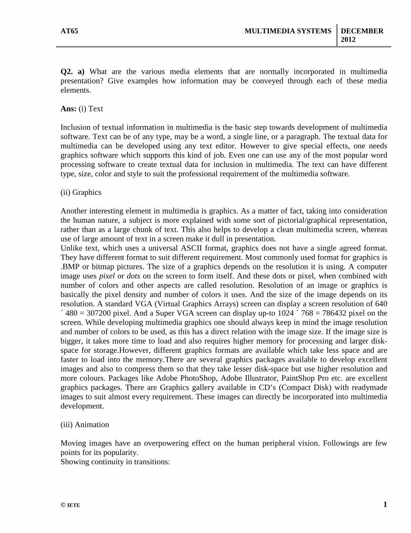
RECORD The RECORD request can be used to send a stream to the server for storage. TEARDOWN A TEARDOWN request is used to terminate the session. It stops all media streams and frees all session related data on the server. b) With the help of a suitable diagram, explain the video transmission and bitrates over ATM. Ans: Video on Demand (VoD) Specification 1.1 provides a reference configuration for the network supplying VoD services (Figure 6). The configuration consists of a server, client, and a separate session/connection control unit. The client could be either a set-top-terminal (STT) or inter working unit (IWU). The reference depicts five communications links which would be served by five separate virtual connections (VC). If the server and client both support signaling (ATM Forum Signaling Specification 4.0), then the user-to-network signaling VC's would be as shown. In the event either the server or the client or both did not support signaling, proxy signaling could be employed as described in a later section. The MPEG-2 Single Program Transport Stream traffic would be accommodated on a separate VC. This VC would be the last VC connection established. The User-to-User Control VC would be used for implementation specific information flows. VoD Specification 1.1 indicates that one of the main purposes for this VC would be to exchange program selection information between the client and the server. This would allow the end user to select a specific item (e.g. a movie) for viewing and inform the server of that selection. The VoD Session Control VC would be used for session control information. This link would be utilized to facilitate connection set up between the server and the client in the event that proxy signaling was required.

AT65 MULTIMEDIA SYSTEMS DECEMBER 2012
© IETE 21
c) Explain the requirement of QOS in a multimedia transmission. Ans: QOS in a multimedia transmission: Quality of service parameters: Supply time for initial connection Fault rate Fault repair time Unsuccessful call ratio Call set-up time Response times for operator services Response time for directory enquiry services Public pay-telephones in working order Bill correctness complaints Q9.a) What is a shading algorithm? How can it be used to depict the plane and curved surfaces? Ans: (Topic 9.15.2) Page No. 371 of Textbook II b) Describe the working principle of encoding digital data on a CD Surface. Differentiate between CD-R and CD-RW. Ans: CDs are used to record music, store data and provide computer software, as most people know. They have replaced magnetic tape and vinyl records as the most common storage and playback method. CDs were expensive to produce in the early years of the technology but now they are inexpensive to produce. We buy them by the dozen in the 21st century. A standard music CD can store more than an hour of music. In computer terms this translates to more than 783 megabytes of data. CDs are thin sheets of plastic made by a process called injection molding. To get an idea of how information is placed on a CD, think about the old vinyl record we had for listening to music. The needle on a record player traveled across the record in one long, continuous spiral. The needle picked up the recorded data (music) and transferred it to the amplifier and speaker so we could hear it. CDCDs work in a similar way. When a compact disc is made the plastic surface is pressed with small knobs or bumps that are also in a continuous spiral. This is covered with a reflective layer and another clear protective layer. The knobs or bumps that make the spiral track are “read” by a laser in the CD player or other electronic equipment. When the CD player motor spins the disc a precise beam of laser light is focused onto the track by a lens. This light follows the spiral track of bumps. Information “read” by the laser is converted in the CD player to sections of data that are moved along the circuit to be amplified for our listening pleasure. This only happens because the laser beam detects the difference between the raised areas and the rest of the CD surface that isn’t raised.
AT65 MULTIMEDIA SYSTEMS DECEMBER 2012
© IETE 22
But what if we want to store music or other data on a CD? This is where encoding comes into play. The music is converted to digital data, a string of numbers that can be interpreted by computers. This is stored on the disc in an exact pattern using the spiral of bumps as the storage medium. When we want to play the music, the CD player or computer “reads” the spiral pattern of numbers and converts this information into music by amplifying the signal for the speaker. PC users have an embarrassment of options these days when it comes to storage: from DAT to Zip, with digital linear tape, floppies, Jaz, Orb, SyQuest, and Travan in between. But, despite these many options, the versatile, inexpensive, and durable compact disc--in its CD-ROM, CD-Recordable, and CD-Rewritable forms--continues to thrive. Some kind of CD drive is standard equipment on most PCs sold today. And with the latest challenger to the throne, Digital Versatile Disc, mired in standards disputes, CD drives are likely to remain the high-capacity drive of choice for most users for years to come. Most CDs can store up to 650MB of data. While standard CD-ROMs can't be "written to" by home users, CD-Rs can be written to once, and CD-RWs can be written to hundreds of times. CD-RW drives offer the added benefit of being able to write to CD-Rs as well. All three disc types store information in grooves that are 1.6 microns wide (a micron is one one-thousandth of a millimeter; the average human hair is about 50 microns wide). Unlike magnetic storage media, such as hard disks, which store data as polarized particles on a magnetic surface, CD-Rs and CD-RWs store data as microscopic reflective and nonreflective spots along the grooves. A drive reads the disc by shining a laser onto its surface and noting how the light reflects (or doesn't) off these spots in the grooves. Mass-produced audio CDs and CD-ROMs are stamped by small presses that create tiny bumps (called lands) and holes (known as pits) in the grooves. Pits reflect light differently than lands along a disc's aluminum or gold surface, and the laser tells the difference by measuring the brightness of the reflection. CD-Rs and CD-RWs contain light-sensitive dyes or chemicals embedded beneath layers of protective plastic. When the high-intensity recording laser hits these light-sensitive materials, they become reflective (or not). CD-ROM, CD-R, CD-RW, and even DVD drives can all read just about any disc type. The exceptions: A few early CD-ROM and some first-generation CD-R drives cannot read rewritable discs. There's less contrast between the reflective and the matte spots on the surface of blank CD-RWs, and the early, less sophisticated laser read-heads can't distinguish between the two. Those drives will simply reject a CD-RW c) Explain in brief the major characteristics of DVD-Video. Ans:
• Support for wide screen movies on standard or wide screen TVs (4:3 and 16:9 aspect ratios). • Over 2 hours of high-quality digital video (a double-sided, dual-layer disc can hold about 8
hours of high-quality video, or 30 hours of VHS quality video).

AT65 MULTIMEDIA SYSTEMS DECEMBER 2012
© IETE 23
• Up to 8 tracks of digital audio (for multiple languages, commentaries, etc.), each with as many as 8 channels.
• Up to 32 subtitle/karaoke tracks. • Automatic seamless branching of video (for multiple story lines or ratings on one disc). • Up to 9 camera angles (different viewpoints can be selected during playback). • On-screen menus and simple interactive features (for games, quizzes, etc.). • Multilingual identifying text for title name, album name, song name, cast, crew, etc. • Instant rewind and fast forward (no "be kind, rewind" stickers and threats on rental discs) • Instant search to title, chapter, music track, and time code. • Durable (no wear from playing, only from physical damage). • Not susceptible to magnetic fields. Resistant to heat. • Compact size (easy to handle, store, and ship; players can be portable; replication is cheaper
than tapes or laserdiscs). • Noncomedogenic.
TextBook
1. Fundamentals of Multimedia, Ze-Nian Li and Mark S. Drew, Pentice Hall, Edition – 2007 2. Principles of Multimedia, Ranjan Parekh, Tata McGraw-Hill, Edition 2006


![AE71/AC67/AT67 DATA COMM. & COMPUTER NETWORKS DEC …iete-elan.ac.in/SolnQPDec2015/Sol_D15_AE71-AC67-AT67.pdf · officially MAC bridge[1]) is a computer networking device that connects](https://img.pdfslide.us/doc/110x75/5edc0dcdad6a402d66668e7b/ae71ac67at67-data-comm-computer-networks-dec-iete-elanacinsolnqpdec2015sold15ae71-ac67-at67pdf.jpg)