Embed Size (px)
Citation preview

✽ Projection lens is optional.
MODEL LC-X6
MULTIMEDIA PROJECTOR
OWNER’S MANUAL
www.touchboards.com 205 Westwood Ave.Long Branch, NJ 07740 1-866-942-6273 [email protected]
2
Features and Design
This Multimedia Projector is designed with most advanced technology for portability, durability, and ease of use. This projectorutilizes built-in multimedia features, a palette of 16.77 million colors, and matrix liquid crystal display (LCD) technology.
◆ Compatibility
The projector widely accepts various video and computerinput signals including; Analog and Digital Computersources, 6 TV color systems, Component video, S-video,Digital video sources compatible with HDCP and RGBscart. (☞ p37 and 38)
◆ Simple Computer System Setting
The projector has the Multi-scan system to conform toalmost all computer output signals quickly. The projectoraccepts signals up to UXGA resolution. (☞ p39 and 72)
◆ Convenient Fingertip Control Pad
The fingertip Control Pad on the projector's top controlsand the remote control provides you a remarkable flexibilityand simplicity through the On-Screen Menu navigation. (☞ p11, 14, 34, and 35)
◆ Easy Menu Operation with USB Mouse
Your USB Mouse Controller can be used for the projector'smenu operation. (☞ p26, 34, and 35)
◆ Vertical and Horizontal Lens Shift and Memory
The projector is equipped with vertical and horizontal LensShift and Lens Memory function, which enables you toobtain optimum image easily under various setupenvironments. (☞ p30 and 55)
◆ One-Touch Removable Filter and Filter LED
One-touch removable fi lter al lows you an easymaintenance and the orange lighting filter LED tells you thebest filter exchange timing. (☞ p63)
◆ Advanced Warp & Blending Feature
This feature responds to commercial needs by allowingedge warp and blending correction for projecting image tothe spherical and cylindrical screens. With the enclosedAdvanced Screen Manager application, you can makecorrection to the projection image from the computerconnected to the projector. (☞ p23)
◆ My Logo
The projector enables you to customize the starting orinterval display for your presentation with its imagecapturing function. (☞ p52)
◆ My Menu Selection
My Menu function allows you to select menu items to bedisplayed on screen. You can hide menus not in frequentuse and make your own menu display. (☞ p51)
◆ Customized Screen Setting
Fine aspect setting menu is prepared in the projector. Youcan adjust screen scale and position exactly what youwant. (☞ p48)
◆ Shutter Function
The projector is equipped with the shutter that providescomplete blackness for a while the projected image is notneeded with keeping the projector on. The Shuttermanagement function allows you to set the timer. Itprevents leaving the projector on with the shutter releasedfor a long time. (☞ p30, 55 and 56)
◆ Film Function
The Film function reproduces pictures faithful to the originalfilm quality from 2:3 and 2:2 pull-down video sources. (☞ p47)
◆ Various Security Functions
The following security or anti-theft functions prevent othersexcept users from using the projector: Key Lock, PJ Lockand USB Lock. (☞ p28, 56, and 57)
◆ Advanced Network Feature
Advanced Network feature available by installation of theoptional interface board enables various networkingoperations including Network Capture, Network Viewer,Network Communication, and Advanced Card Imager. Contact the sales dealer where you purchase the projectorfor the Advanced Network board. (☞ p75)
3
Table of Contents
Features and Design . . . . . . . . . . . . . . . . . . .2
Table of Contents . . . . . . . . . . . . . . . . . . . . . .3
To The Owner . . . . . . . . . . . . . . . . . . . . . . . . .4
Safety Instructions . . . . . . . . . . . . . . . . . . . .5
Air Circulation . . . . . . . . . . . . . . . . . . . . . . . . . . . . . . .6Setup In Proper Directions . . . . . . . . . . . . . . . . . . . . .6Moving the Projector . . . . . . . . . . . . . . . . . . . . . . . . .7Caution in Handling the Projector . . . . . . . . . . . . . . . .7
Compliance . . . . . . . . . . . . . . . . . . . . . . . . . .8
Preparation . . . . . . . . . . . . . . . . . . . . . . . . . . .9
Parts Name . . . . . . . . . . . . . . . . . . . . . . . . . . . . . . . .9Indicators . . . . . . . . . . . . . . . . . . . . . . . . . . . . . . . . .10Top Control . . . . . . . . . . . . . . . . . . . . . . . . . . . . . . . .11Terminals . . . . . . . . . . . . . . . . . . . . . . . . . . . . . . . . .12Remote Control . . . . . . . . . . . . . . . . . . . . . . . . . . . .14Remote Control Transmitter . . . . . . . . . . . . . . . . . . .16Remote Control Channel and ID Setup . . . . . . . . . . .16Remote Control Battery Installation . . . . . . . . . . . . .17
Installation . . . . . . . . . . . . . . . . . . . . . . . . . .18
Installation . . . . . . . . . . . . . . . . . . . . . . . . . . . . . . . . .18Lens Installation . . . . . . . . . . . . . . . . . . . . . . . . . . . .18Positioning the Projector . . . . . . . . . . . . . . . . . . . . . .18Lens Shift Adjustment . . . . . . . . . . . . . . . . . . . . . . .19Level Adjustable Feet . . . . . . . . . . . . . . . . . . . . . . . .19Connecting AC Power Cord . . . . . . . . . . . . . . . . . . .20Connection Terminals . . . . . . . . . . . . . . . . . . . . . . .21Interface Board Slots . . . . . . . . . . . . . . . . . . . . . . . .21Connecting to Computer (Digital and Analog RGB) . . . . . . . . . . . . . . . . . . . . . .22Connecting to Digital PC/AV Equipment (Warp & Blending) . . . . . . . . . . . . . . . . . . . . . . . . . . .23Connecting to Video Equipment (Digital and Video) . . . . . . . . . . . . . . . . . . . . . . . . . . .24Connecting to Video Equipment (Component and RGB Scart) . . . . . . . . . . . . . . . . . . .25
Basic Operation . . . . . . . . . . . . . . . . . . . . . .26
Operating the Projector . . . . . . . . . . . . . . . . . . . . . .26Basic Operation and Reference Buttons . . . . . . . . .27Turning On the Projector . . . . . . . . . . . . . . . . . . . . .28Turning Off the Projector . . . . . . . . . . . . . . . . . . . . .29Lens Shift Adjustment . . . . . . . . . . . . . . . . . . . . . . .30Zoom and Focus Adjustment . . . . . . . . . . . . . . . . . .30Shutter Function . . . . . . . . . . . . . . . . . . . . . . . . . . . .30Input Selection . . . . . . . . . . . . . . . . . . . . . . . . . . . . .31Auto PC Adjustment . . . . . . . . . . . . . . . . . . . . . . . . .31Information . . . . . . . . . . . . . . . . . . . . . . . . . . . . . . . .31Keystone Adjustment . . . . . . . . . . . . . . . . . . . . . . . .32Screen Selection . . . . . . . . . . . . . . . . . . . . . . . . . . . .32Picture Freeze Function . . . . . . . . . . . . . . . . . . . . . .32P-Timer Function . . . . . . . . . . . . . . . . . . . . . . . . . . . .32D. Zoom +/– Function . . . . . . . . . . . . . . . . . . . . . . . .33
Volume Control . . . . . . . . . . . . . . . . . . . . . . . . . . . . .33How to Operate the On-Screen Menu . . . . . . . . . . .34Menu Icons and Their Features . . . . . . . . . . . . . . . .36
Input . . . . . . . . . . . . . . . . . . . . . . . . . . . . . . .37
Input . . . . . . . . . . . . . . . . . . . . . . . . . . . . . . . . . . . . .37
System . . . . . . . . . . . . . . . . . . . . . . . . . . . . .39
System . . . . . . . . . . . . . . . . . . . . . . . . . . . . . . . . . . .39PC System Selection 39Video or S-Video Signal Selection 40Component Signal Selection 40
Computer Adjustment . . . . . . . . . . . . . . . .41
PC Adjustment . . . . . . . . . . . . . . . . . . . . . . . . . . . . .41Auto PC Adjust 41Manual PC Adjust 42
Image Adjustment . . . . . . . . . . . . . . . . . . . .44
Image . . . . . . . . . . . . . . . . . . . . . . . . . . . . . . . . . . . .44Image Adjust . . . . . . . . . . . . . . . . . . . . . . . . . . . . . .45
Screen Setting . . . . . . . . . . . . . . . . . . . . . . .48
Screen Setting . . . . . . . . . . . . . . . . . . . . . . . . . . . . .48
Sound . . . . . . . . . . . . . . . . . . . . . . . . . . . . . .50
Sound . . . . . . . . . . . . . . . . . . . . . . . . . . . . . . . . . . . .50
Setting . . . . . . . . . . . . . . . . . . . . . . . . . . . . .51
Setting . . . . . . . . . . . . . . . . . . . . . . . . . . . . . . . . . . .51
Special . . . . . . . . . . . . . . . . . . . . . . . . . . . . .59
Special . . . . . . . . . . . . . . . . . . . . . . . . . . . . . . . . . . .59Information . . . . . . . . . . . . . . . . . . . . . . . . . . . . . . . .61
Maintenance and Cleaning . . . . . . . . . . . . .62
Warning Temp Indicator . . . . . . . . . . . . . . . . . . . . . .62Air Filter Replacement . . . . . . . . . . . . . . . . . . . . . . .63Lamp Replacement . . . . . . . . . . . . . . . . . . . . . . . . . .64Cleaning the Projection Lens . . . . . . . . . . . . . . . . . .66Cleaning the Projector Cabinet . . . . . . . . . . . . . . . . .66Attaching the Cord Cover Strap . . . . . . . . . . . . . . . .66Indicators and Projector Condition . . . . . . . . . . . . . .67
Main Indicators 67Shutter Indicator 68Warning Filter Indicator 68Lamp Replace Indicators 69
Appendix . . . . . . . . . . . . . . . . . . . . . . . . . . .70
Troubleshooting . . . . . . . . . . . . . . . . . . . . . . . . . . . .70Compatible Computer Specifications . . . . . . . . . . . .72Technical Specifications . . . . . . . . . . . . . . . . . . . . . .74Optional Parts . . . . . . . . . . . . . . . . . . . . . . . . . . . . . .75Menu Tree . . . . . . . . . . . . . . . . . . . . . . . . . . . . . . . .76Dimensions . . . . . . . . . . . . . . . . . . . . . . . . . . . . . . . .79Terminal Configurations . . . . . . . . . . . . . . . . . . . . . .80PIN Code Number Memo . . . . . . . . . . . . . . . . . . . . .81Index . . . . . . . . . . . . . . . . . . . . . . . . . . . . . . . . . . . . .82
4
To The Owner
CAUTION : TO REDUCE THE RISK OF ELECTRIC
SHOCK, DO NOT REMOVE COVER (OR
BACK). NO USER-SERVICEABLE PARTS
INSIDE EXCEPT LAMP REPLACEMENT.
REFER SERVICING TO QUALIFIED
SERVICE PERSONNEL.
THIS SYMBOL INDICATES THAT DANGEROUSVOLTAGE CONSTITUTING A RISK OF ELECTRICSHOCK IS PRESENT WITHIN THIS UNIT.
THIS SYMBOL INDICATES THAT THERE AREIMPORTANT OPERATING AND MAINTENANCEINSTRUCTIONS IN THE OWNER'S MANUAL WITHTHIS UNIT.
CAUTION
RISK OF ELECTRIC SHOCK
DO NOT OPEN
Before operating this projector, read this manual thoroughlyand operate the projector properly. This projector provides many convenient features andfunctions. Operating the projector properly enables you tomanage those features and maintains it in better condition fora considerable time.Improper operation may result in not only shortening theproduct-life, but also malfunctions, fire hazard, or otheraccidents.If your projector seems to operate improperly, read thismanual again, check operations and cable connections and trythe solutions in the “Troubleshooting” section in the end ofthis booklet. If the problem still persists, contact the dealerwhere you purchased the projector or the service center.
Safety Precaution
WARNING : TO REDUCE THE RISK OF FIRE OR ELECTRIC
SHOCK, DO NOT EXPOSE THIS APPLIANCE
TO RAIN OR MOISTURE.
– This projector produces intense light from the projectionlens. Do not stare directly into the lens as possible. Eyedamage could result. Be especially careful that children donot stare directly into the beam.
– Install the projector in a proper position. If not, it mayresult in a fire hazard.
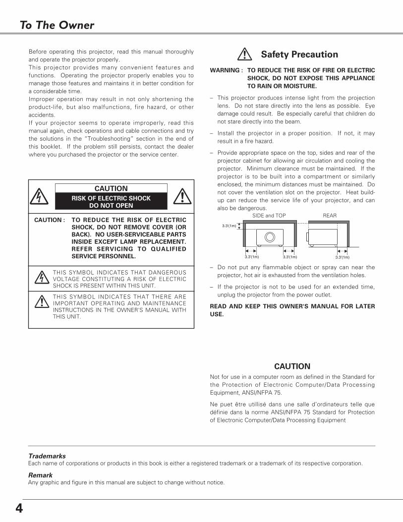
– Provide appropriate space on the top, sides and rear of theprojector cabinet for allowing air circulation and cooling theprojector. Minimum clearance must be maintained. If theprojector is to be built into a compartment or similarlyenclosed, the minimum distances must be maintained. Donot cover the ventilation slot on the projector. Heat build-up can reduce the service life of your projector, and canalso be dangerous.
– Do not put any flammable object or spray can near theprojector, hot air is exhausted from the ventilation holes.
– If the projector is not to be used for an extended time,unplug the projector from the power outlet.
READ AND KEEP THIS OWNER'S MANUAL FOR LATER
USE.
3.3'(1m) 3.3'(1m) 3.3'(1m)
3.3'(1m)
SIDE and TOP REAR
CAUTION
Not for use in a computer room as defined in the Standard forthe Protection of Electronic Computer/Data ProcessingEquipment, ANSI/NFPA 75.
Ne puet être utillisé dans une salle d’ordinateurs telle quedéfinie dans la norme ANSI/NFPA 75 Standard for Protectionof Electronic Computer/Data Processing Equipment
TrademarksEach name of corporations or products in this book is either a registered trademark or a trademark of its respective corporation.
RemarkAny graphic and figure in this manual are subject to change without notice.
5
Safety Instructions
All the safety and operating instructions should be read beforethe product is operated.
Read all of the instructions given here and retain them for lateruse. Unplug this projector from AC power supply beforecleaning. Do not use liquid or aerosol cleaners. Use a dampcloth for cleaning.
Follow all warnings and instructions marked on the projector.
For added protection to the projector during a lightning storm,or when it is left unattended and unused for long periods oftime, unplug it from the wall outlet. This will prevent damagedue to lightning and power line surges.
Do not expose this unit to rain or use near water... forexample, in a wet basement, near a swimming pool, etc...
Do not use attachments not recommended by themanufacturer as they may cause hazards.
Do not place this projector on an unstable cart, stand, or table.The projector may fall, causing serious injury to a child oradult, and serious damage to the projector. Use only with acart or stand recommended by the manufacturer, or sold withthe projector. Wall or shelf mounting should follow themanufacturer's instructions, and should use a mounting kitapproved by the manufacturers.
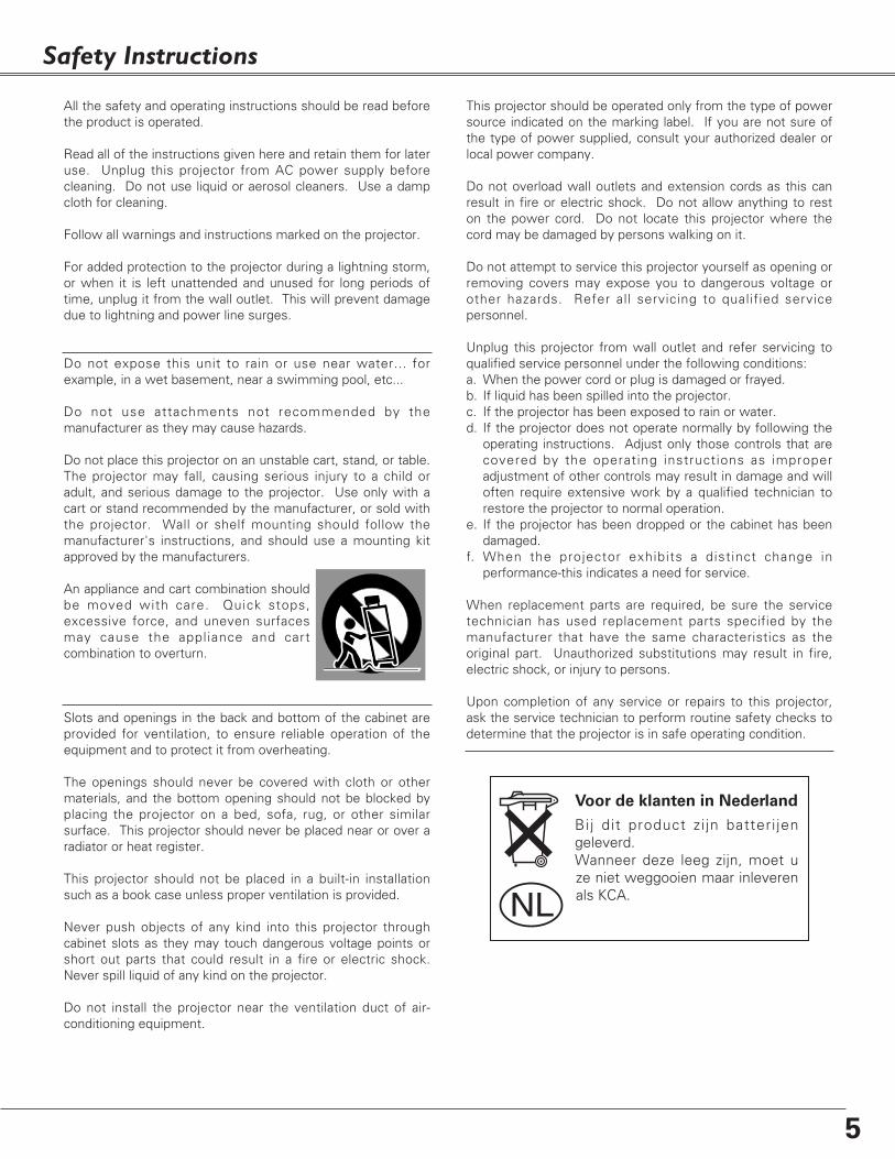
An appliance and cart combination shouldbe moved with care. Quick stops,excessive force, and uneven surfacesmay cause the appliance and cartcombination to overturn.
Slots and openings in the back and bottom of the cabinet areprovided for ventilation, to ensure reliable operation of theequipment and to protect it from overheating.
The openings should never be covered with cloth or othermaterials, and the bottom opening should not be blocked byplacing the projector on a bed, sofa, rug, or other similarsurface. This projector should never be placed near or over aradiator or heat register.
This projector should not be placed in a built-in installationsuch as a book case unless proper ventilation is provided.
Never push objects of any kind into this projector throughcabinet slots as they may touch dangerous voltage points orshort out parts that could result in a fire or electric shock.Never spill liquid of any kind on the projector.
Do not install the projector near the ventilation duct of air-conditioning equipment.
This projector should be operated only from the type of powersource indicated on the marking label. If you are not sure ofthe type of power supplied, consult your authorized dealer orlocal power company.
Do not overload wall outlets and extension cords as this canresult in fire or electric shock. Do not allow anything to reston the power cord. Do not locate this projector where thecord may be damaged by persons walking on it.
Do not attempt to service this projector yourself as opening orremoving covers may expose you to dangerous voltage orother hazards. Refer all servicing to qualified servicepersonnel.
Unplug this projector from wall outlet and refer servicing toqualified service personnel under the following conditions:a. When the power cord or plug is damaged or frayed.b. If liquid has been spilled into the projector.c. If the projector has been exposed to rain or water.d. If the projector does not operate normally by following the
operating instructions. Adjust only those controls that arecovered by the operating instructions as improperadjustment of other controls may result in damage and willoften require extensive work by a qualified technician torestore the projector to normal operation.
e. If the projector has been dropped or the cabinet has beendamaged.
f. When the projector exhibits a distinct change inperformance-this indicates a need for service.
When replacement parts are required, be sure the servicetechnician has used replacement parts specified by themanufacturer that have the same characteristics as theoriginal part. Unauthorized substitutions may result in fire,electric shock, or injury to persons.
Upon completion of any service or repairs to this projector,ask the service technician to perform routine safety checks todetermine that the projector is in safe operating condition.
Voor de klanten in Nederland
Bij dit product zi jn batteri jengeleverd. Wanneer deze leeg zijn, moet uze niet weggooien maar inleverenals KCA.NL
6
Safety Instructions
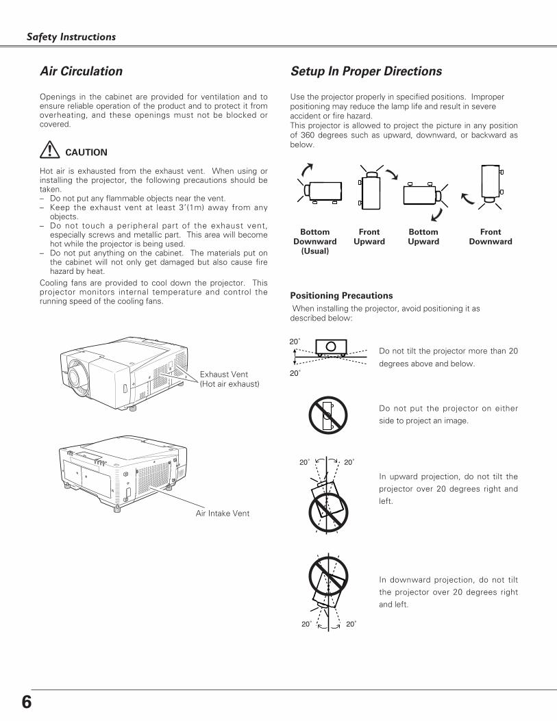
Openings in the cabinet are provided for ventilation and toensure reliable operation of the product and to protect it fromoverheating, and these openings must not be blocked orcovered.
CAUTION
Hot air is exhausted from the exhaust vent. When using orinstalling the projector, the following precautions should betaken. – Do not put any flammable objects near the vent.– Keep the exhaust vent at least 3’(1m) away from any
objects.– Do not touch a peripheral part of the exhaust vent,
especially screws and metallic part. This area will becomehot while the projector is being used.
– Do not put anything on the cabinet. The materials put onthe cabinet will not only get damaged but also cause firehazard by heat.
Cooling fans are provided to cool down the projector. Thisprojector monitors internal temperature and control therunning speed of the cooling fans.
Air Intake Vent
Exhaust Vent(Hot air exhaust)
Do not tilt the projector more than 20
degrees above and below.
In upward projection, do not tilt theprojector over 20 degrees right andleft.
Do not put the projector on eitherside to project an image.
20˚
20˚
In downward projection, do not tiltthe projector over 20 degrees rightand left.
Use the projector properly in specified positions. Improperpositioning may reduce the lamp life and result in severeaccident or fire hazard.This projector is allowed to project the picture in any positionof 360 degrees such as upward, downward, or backward asbelow.
Bottom
Downward
(Usual)
Front
Downward
Bottom
Upward
Front
Upward
Setup In Proper Directions
When installing the projector, avoid positioning it asdescribed below:
Positioning Precautions
Air Circulation
7
Safety Instructions
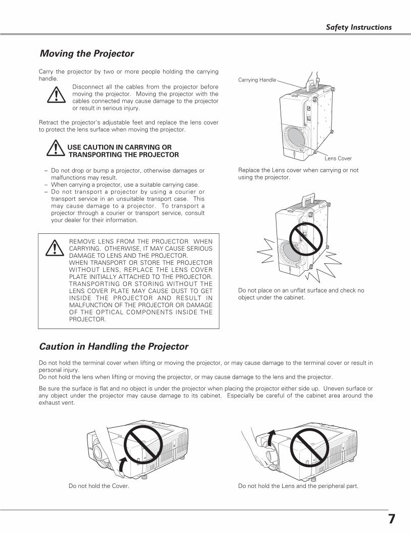
USE CAUTION IN CARRYING OR TRANSPORTING THE PROJECTOR
– Do not drop or bump a projector, otherwise damages ormalfunctions may result.
– When carrying a projector, use a suitable carrying case.– Do not transport a projector by using a courier or
transport service in an unsuitable transport case. Thismay cause damage to a projector. To transport aprojector through a courier or transport service, consultyour dealer for their information.
Carry the projector by two or more people holding the carryinghandle. Carrying Handle
Caution in Handling the Projector
REMOVE LENS FROM THE PROJECTOR WHENCARRYING. OTHERWISE, IT MAY CAUSE SERIOUSDAMAGE TO LENS AND THE PROJECTOR.WHEN TRANSPORT OR STORE THE PROJECTORWITHOUT LENS, REPLACE THE LENS COVERPLATE INITIALLY ATTACHED TO THE PROJECTOR.TRANSPORTING OR STORING WITHOUT THELENS COVER PLATE MAY CAUSE DUST TO GETINSIDE THE PROJECTOR AND RESULT INMALFUNCTION OF THE PROJECTOR OR DAMAGEOF THE OPTICAL COMPONENTS INSIDE THEPROJECTOR.
Retract the projector's adjustable feet and replace the lens coverto protect the lens surface when moving the projector.
Disconnect all the cables from the projector beforemoving the projector. Moving the projector with thecables connected may cause damage to the projectoror result in serious injury.
Do not hold the terminal cover when lifting or moving the projector, or may cause damage to the terminal cover or result inpersonal injury.Do not hold the lens when lifting or moving the projector, or may cause damage to the lens and the projector.
Be sure the surface is flat and no object is under the projector when placing the projector either side up. Uneven surface orany object under the projector may cause damage to its cabinet. Especially be careful of the cabinet area around theexhaust vent.
Lens Cover
Do not place on an unflat surface and check noobject under the cabinet.
Replace the Lens cover when carrying or notusing the projector.
Do not hold the Cover. Do not hold the Lens and the peripheral part.
Moving the Projector

8
Compliance
Federal Communication Commission Notice
This equipment has been tested and found to comply with the limits for a Class A digital device, pursuant to Part 15 of FCCRules. These limits are designed to provide reasonable protection against harmful interference when the equipment isoperated in a commercial environment. This equipment generates, uses, and can radiate radio frequency energy and, if notinstalled and used in accordance with the instruction manual, may cause harmful interference to radio communications.Operation of this equipment in a residential area is likely to cause harmful interference in which case the user will berequired to correct the interference at his own expense.Do not make any changes or modifications to the equipment unless otherwise specified in the instructions. If such changesor modifications should be made, you could be required to stop operation of the equipment.
CAUTIONThis is a Class A equipment. This equipment can cause interference in residential areas; in this case, the operator can beasked to take adequate countermeasures.
The AC Power Cord supplied with this projector meets the requirement for use in the country you purchased it.
AC Power Cord for the United States and Canada :AC Power Cord used in the United States and Canada is listed by the Underwriters Laboratories (UL) andcertified by the Canadian Standard Association (CSA).AC Power Cord has a grounding-type AC line plug. This is a safety feature to be sure that the plug will fit intothe power outlet. Do not try to defeat this safety feature. Should you be unable to insert the plug into theoutlet, contact your electrician. GROUND
THE SOCKET-OUTLET SHOULD BE INSTALLED NEAR THE EQUIPMENT AND EASILY ACCESSIBLE.
AC Power Cord Requirement
9
Bottom
Back
Front
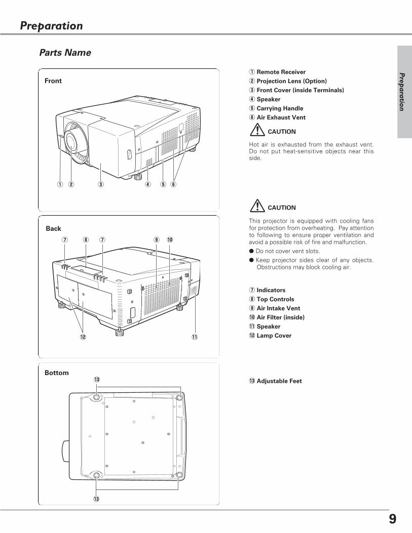
q Remote Receiver
w Projection Lens (Option)
e Front Cover (inside Terminals)
r Speaker
t Carrying Handle
y Air Exhaust Vent
u Indicators
i Top Controls
o Air Intake Vent
!0 Air Filter (inside)
!1 Speaker
!2 Lamp Cover
!3 Adjustable Feet
q w e t y
u i o
!3
!3
!0
!1
CAUTION
Hot air is exhausted from the exhaust vent.Do not put heat-sensitive objects near thisside.
CAUTION
This projector is equipped with cooling fansfor protection from overheating. Pay attentionto following to ensure proper ventilation andavoid a possible risk of fire and malfunction.● Do not cover vent slots.● Keep projector sides clear of any objects.
Obstructions may block cooling air.
!2
r
Parts Name
PreparationP
reparation
u
10
Preparation
q w e r t y u
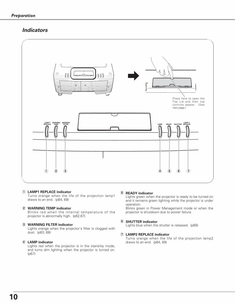
q LAMP1 REPLACE indicatorTurns orange when the life of the projection lamp1draws to an end. (p64, 69)
w WARNING TEMP indicatorBlinks red when the internal temperature of theprojector is abnormally high. (p62,67)
t READY indicatorLights green when the projector is ready to be turned onand it remains green lighting while the projector is underoperation.Blinks green in Power Management mode or when theprojector is shutdown due to power failure.
Indicators
r LAMP indicatorLights red when the projector is in the stand-by mode,and turns dim lighting when the projector is turned on.(p67)
e WARNING FILTER indicatorLights orange when the projector's filter is clogged withdust. (p63, 68)
u LAMP2 REPLACE indicatorTurns orange when the life of the projection lamp2draws to an end. (p64, 69)
y SHUTTER indicatorLights blue when the shutter is released. (p68)
Press here to open theTop Lid and then topcontrols appear. (Seenext page.)
11
Preparation
Top Control
LENSSHIFT MENU
CANCEL
SELECT
ZOOM
FOCUS
SHUTTER
INPUT
INFO.
AUTOPC ADJ.
POWER P
q w e r t y
o i
u
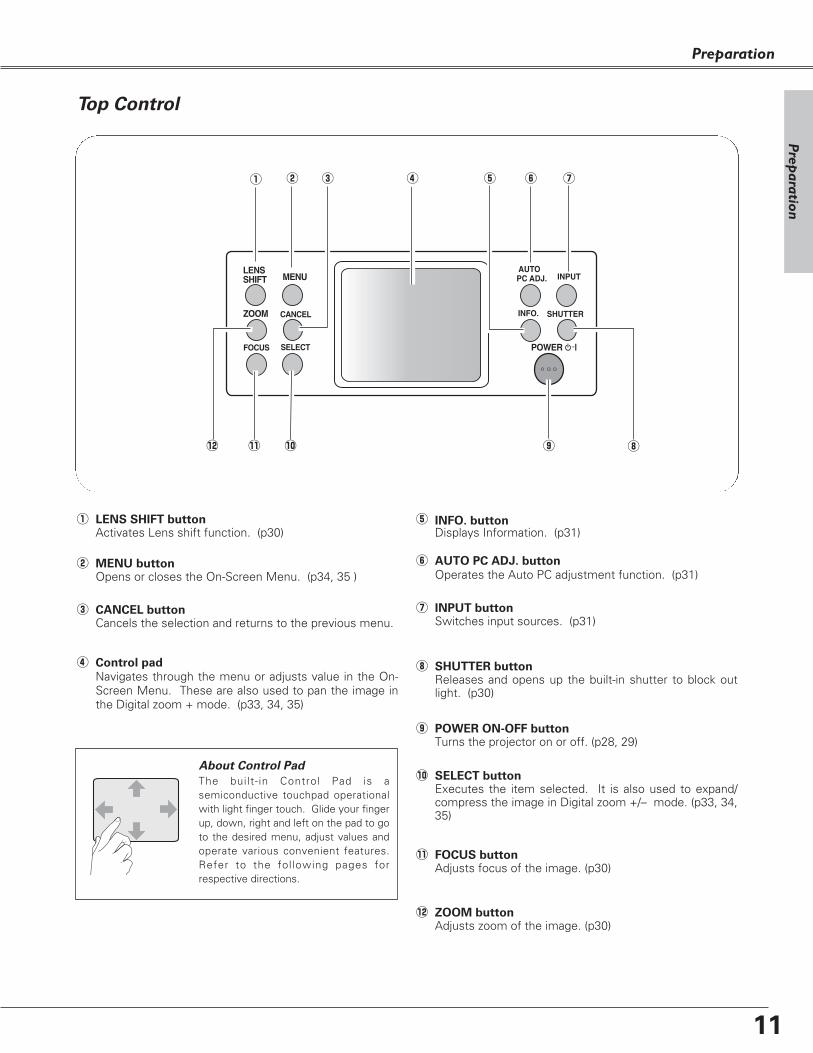
u INPUT buttonSwitches input sources. (p31)
y AUTO PC ADJ. button
Operates the Auto PC adjustment function. (p31)
e CANCEL buttonCancels the selection and returns to the previous menu.
t INFO. buttonDisplays Information. (p31)
w MENU buttonOpens or closes the On-Screen Menu. (p34, 35 )
o POWER ON-OFF buttonTurns the projector on or off. (p28, 29)
i SHUTTER buttonReleases and opens up the built-in shutter to block outlight. (p30)
r Control pad
Navigates through the menu or adjusts value in the On-Screen Menu. These are also used to pan the image inthe Digital zoom + mode. (p33, 34, 35)
q LENS SHIFT button Activates Lens shift function. (p30)
!0!1!2
!0 SELECT buttonExecutes the item selected. It is also used to expand/compress the image in Digital zoom +/– mode. (p33, 34,35)
!1 FOCUS buttonAdjusts focus of the image. (p30)
!2 ZOOM buttonAdjusts zoom of the image. (p30)
About Control Pad
The built- in Control Pad is asemiconductive touchpad operationalwith light finger touch. Glide your fingerup, down, right and left on the pad to goto the desired menu, adjust values andoperate various convenient features.Refer to the following pages forrespective directions.
Prep
aration
12
Preparation
ANALOG OUTINPUT 3INPUT 1
INPUT 2
ANALOG INDIGITAL (DVI-D)AUDIO 1
AUDIO 2
VIDEO/Y Cb/Pb Cr/Pr
G B R H/V V VIDEO/Y Cb/Pb Cr/Pr
S-VIDEO
R-AUDIO-L
(MONO)
Terminals
q
w
e
r
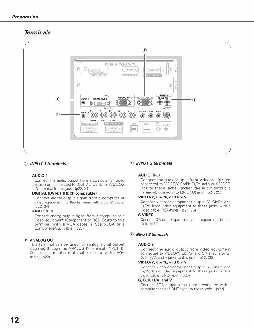
e INPUT 3 terminals
AUDIO (R-L)
Connect the audio output from video equipmentconnected to VIDEO/Y Cb/Pb Cr/Pr jacks or S-VIDEOjack to these jacks. (When the audio output ismonaural, connect it to L(MONO) jack. (p24, 25)
VIDEO/Y, Cb/Pb, and Cr/Pr
Connect video or component output (Y, Cb/Pb andCr/Pr) from video equipment to these jacks with avideo cable (RCA-type). (p24, 25)
S-VIDEO
Connect S-Video output from video equipment to thisjack. (p24)
r INPUT 2 terminals
AUDIO 2
Connect the audio output from video equipmentconnected to VIDEO/Y, Cb/Pb, and Cr/Pr jacks or G,B, R, H/V, and V jacks to this jack. (p22, 25)
VIDEO/Y, Cb/Pb, and Cr/Pr
Connect video or component output (Y, Cb/Pb andCr/Pr) from video equipment to these jacks with avideo cable (BNC-type). (p25)
G, B, R, H/V, and V
Connect RGB output signal from a computer with acomputer cable (5 BNC-type) to these jacks. (p22)
w ANALOG OUTThis terminal can be used for analog signal outputincoming through the ANALOG IN terminal (INPUT 1).Connect this terminal to the other monitor with a VGAcable. (p22)
q INPUT 1 terminals
AUDIO 1
Connect the audio output from a computer or videoequipment connected to DIGITAL (DVI-D) or ANALOGIN terminal to this jack. (p22, 24)
DIGITAL (DVI-D) (HDCP compatible)
Connect digital output signal from a computer orvideo equipment to this terminal with a DVI-D cable.(p22, 24)
ANALOG IN
Connect analog output signal from a computer or avideo equipment (Component or RGB Scart) to thisterminal with a VGA cable, a Scart-VGA or aComponent-VGA cable. (p22)
13
Preparation
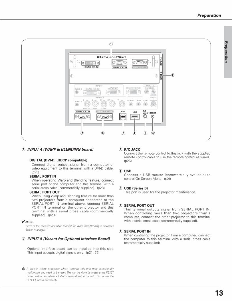
A built-in micro processor which controls this unit may occasionallymalfunction and need to be reset. This can be done by pressing the RESET button with a pen, which will shut down and restart the unit. Do not use theRESET function excessively.
q
ertyu
u SERIAL PORT INWhen controling the projector from a computer, connectthe computer to this terminal with a serial cross cable(commercially supplied).
t USB (Series B)This port is used for the projector maintenance.
y SERIAL PORT OUTThis terminal outputs signal from SERIAL PORT IN.When controling more than two projectors from acomputer, connect the other projector to this terminalwith a serial cross cable (commercially supplied).
e R/C JACKConnect the remote control to this jack with the suppliedremote control cable to use the remote control as wired.(p26)
✽
✽
q INPUT 4 (WARP & BLENDING board)
DIGITAL (DVI-D) (HDCP compatible)
Connect digital output signal from a computer orvideo equipment to this terminal with a DVI-D cable.(p23)
SERIAL PORT INWhen operating Warp and Blending feature, connectserial port of the computer and this terminal with aserial cross cable (commercially supplied). (p23)
SERIAL PORT OUTWhen using Warp and Blending feature for more thantwo projectors from a computer connected to theSERIAL PORT IN terminal above, connect SERIALPORT IN terminal on the other projector and thisterminal with a serial cross cable (commerciallysupplied). (p23)
r USB Connect a USB mouse (commercially available) tocontrol On-Screen Menu. (p26)
Prep
aration
✔Note:Refer to the enclosed operation manual for Warp and Blending in AdvancedScreen Manager.
w
w INPUT 5 (Vacant for Optional Interface Board)
Optional interface board can be installed into this slot.This input accepts digital signals only. (p21, 75)
14
Preparation
Remote Control
MENU
C A N C E L
INFO AUTO PC
SCREENFREEZE
P-TIMERSOUND
REMOTE
VOL.
MUTE
CH
ID
L E N S S H I F T
K E Y S T O N EK E Y S T O N E
S H U T T E R D . Z O O M
Z O O M F O C U S
O N - O F F
MENU
C A N C E L
INFO AUTO PC
SCREENFREEZE
P-TIMERSOUND
REMOTE
VOL.
MUTE
CH
ID
L E N S S H I F T
K E Y S T O N E
S H U T T E R D . Z O O M
Z O O M F O C U S
O N - O F F
q
w
u
i
e
r
y
!0
o
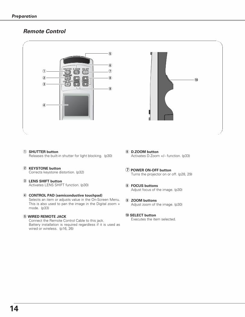
o ZOOM buttonsAdjust zoom of the image. (p30)
r CONTROL PAD (semiconductive touchpad)
Selects an item or adjusts value in the On-Screen Menu.This is also used to pan the image in the Digital zoom +mode. (p33)
w KEYSTONE buttonCorrects keystone distortion. (p32) u POWER ON-OFF button
Turns the projector on or off. (p28, 29)
e LENS SHIFT buttonActivates LENS SHIFT function. (p30) i FOCUS buttons
Adjust focus of the image. (p30)
t WIRED REMOTE JACKConnect the Remote Control Cable to this jack.Battery installation is required regardless if it is used aswired or wireless. (p16, 26)
!0 SELECT buttonExecutes the item selected.
t
y D.ZOOM buttonActivates D.Zoom +/– function. (p33)
q SHUTTER buttonReleases the built-in shutter for light blocking. (p30)
15
Preparation
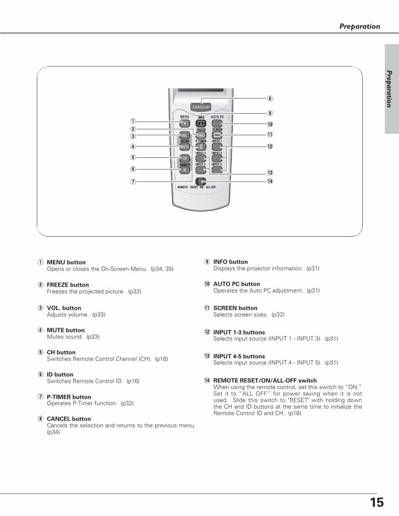
!1 SCREEN buttonSelects screen sizes. (p32)
!2 INPUT 1-3 buttonsSelects input source (INPUT 1 - INPUT 3). (p31)
!0 AUTO PC buttonOperates the Auto PC adjustment. (p31)
q MENU buttonOpens or closes the On-Screen Menu. (p34, 35)
w FREEZE buttonFreezes the projected picture. (p32)
!4 REMOTE RESET/ON/ALL-OFF switchWhen using the remote control, set this switch to “ON.”Set it to “ALL OFF” for power saving when it is notused. Slide this switch to "RESET" with holding downthe CH and ID buttons at the same time to initialize theRemote Control ID and CH. (p16)
u P-TIMER buttonOperates P-Timer function. (p32)
MENU
C A N C E L
INFOINFO AUTO PC
SCREENSCREENFREEZEFREEZE
P-TIMERP-TIMERSOUNDSOUND
REMOTEREMOTE
VOL.
MUTE
CH
ID
INPUT 4
INPUT 1
INPUT 2
INPUT 3INPUT 5
REMOTE RESET ON ALL OFF
L E N S S H I F T
K E Y S T O N E
S H U T T E R D . Z O O M
Z O O M F O C U S
O N - O F F
q
e
!0
!1
t
y
o
!3
i
r
u !4
w
!2
e VOL. buttonAdjusts volume. (p33)
r MUTE buttonMutes sound. (p33)
t CH buttonSwitches Remote Control Channel (CH). (p16)
y ID buttonSwitches Remote Control ID. (p16)
i CANCEL buttonCancels the selection and returns to the previous menu.(p34)
o INFO buttonDisplays the projector information. (p31)
!3 INPUT 4-5 buttonsSelects input source (INPUT 4 - INPUT 5). (p31)
Prep
aration
16
Preparation
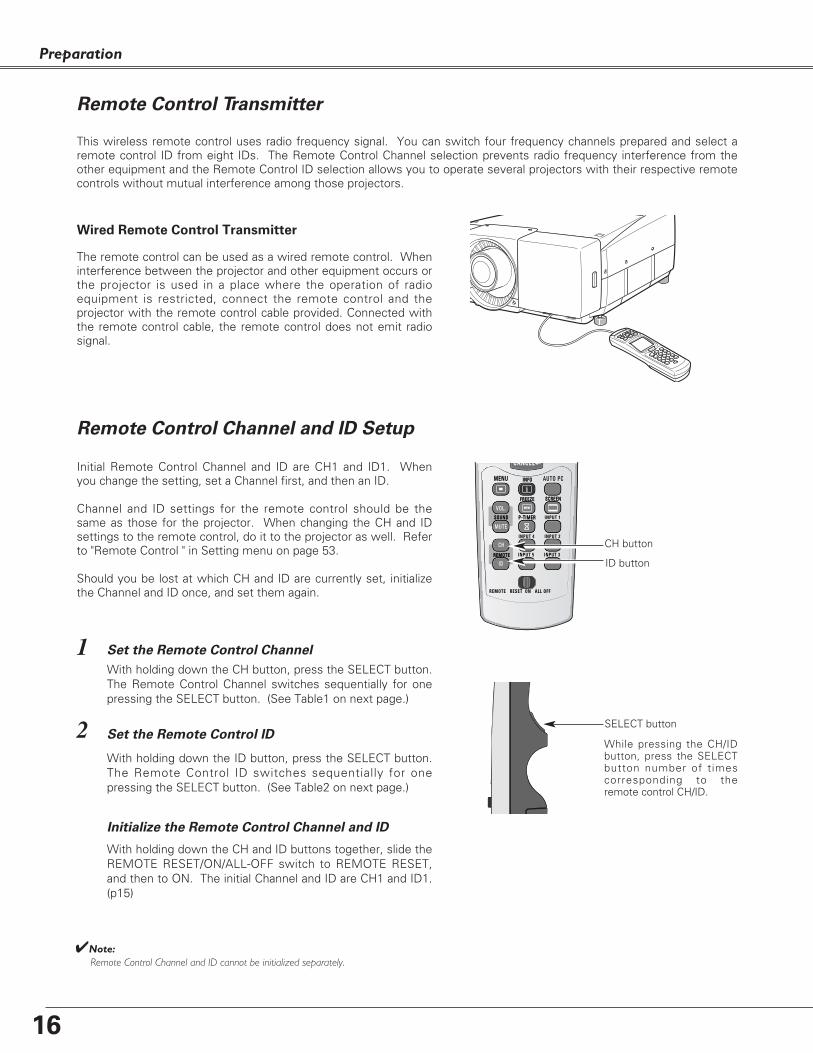
This wireless remote control uses radio frequency signal. You can switch four frequency channels prepared and select aremote control ID from eight IDs. The Remote Control Channel selection prevents radio frequency interference from theother equipment and the Remote Control ID selection allows you to operate several projectors with their respective remotecontrols without mutual interference among those projectors.
Wired Remote Control Transmitter
The remote control can be used as a wired remote control. Wheninterference between the projector and other equipment occurs orthe projector is used in a place where the operation of radioequipment is restricted, connect the remote control and theprojector with the remote control cable provided. Connected withthe remote control cable, the remote control does not emit radiosignal.
Remote Control Channel and ID Setup
Initial Remote Control Channel and ID are CH1 and ID1. Whenyou change the setting, set a Channel first, and then an ID.
Channel and ID settings for the remote control should be thesame as those for the projector. When changing the CH and IDsettings to the remote control, do it to the projector as well. Referto "Remote Control " in Setting menu on page 53.
Should you be lost at which CH and ID are currently set, initializethe Channel and ID once, and set them again.
With holding down the CH button, press the SELECT button.The Remote Control Channel switches sequentially for onepressing the SELECT button. (See Table1 on next page.)
With holding down the CH and ID buttons together, slide theREMOTE RESET/ON/ALL-OFF switch to REMOTE RESET,and then to ON. The initial Channel and ID are CH1 and ID1.(p15)
1
MENUMENU
C A N C E LC A N C E L
INFOINFO AUTO PC
SCREENSCREENFREEZEFREEZE
P-TIMERP-TIMERSOUNDSOUND
REMOTEREMOTE
VOL.
MUTE
CH
ID
INPUT 4
INPUT 1
INPUT 2
INPUT 3INPUT 5
REMOTE RESET ON ALL OFF
L E N S S H I F T
K E Y S T O N E
S H U T T E R D . Z O O M
Z O O M F O C U S
O N - O F F
While pressing the CH/IDbutton, press the SELECTbutton number of timescorresponding to theremote control CH/ID. MENU
C A N C E L
INFO AUTO PC
SCREENFREEZE
P-TIMERSOUND
REMOTE
VOL.
MUTE
CH
ID
L E N S S H I F T
K E Y S T O N E
S H U T T E R D . Z O O M
Z O O M F O C U S
O N - O F F
ID button
CH button
SELECT button
✔Note:Remote Control Channel and ID cannot be initialized separately.
Set the Remote Control Channel
Set the Remote Control ID2With holding down the ID button, press the SELECT button.The Remote Control ID switches sequentially for onepressing the SELECT button. (See Table2 on next page.)
Initialize the Remote Control Channel and ID
Remote Control Transmitter
17
Preparation
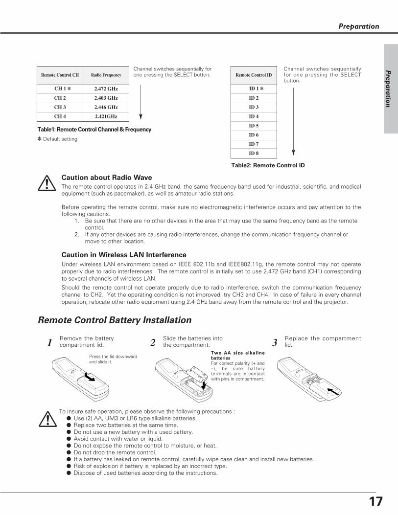
Remote Control Battery Installation
To insure safe operation, please observe the following precautions :● Use (2) AA, UM3 or LR6 type alkaline batteries.● Replace two batteries at the same time.● Do not use a new battery with a used battery.● Avoid contact with water or liquid.● Do not expose the remote control to moisture, or heat.● Do not drop the remote control.● If a battery has leaked on remote control, carefully wipe case clean and install new batteries.● Risk of explosion if battery is replaced by an incorrect type. ● Dispose of used batteries according to the instructions.
Press the lid downwardand slide it.
Remove the batterycompartment lid.
Slide the batteries intothe compartment.
Replace the compartmentlid.
Two AA size alkalinebatteriesFor correct polarity (+ and–), be sure batteryterminals are in contactwith pins in compartment.
1 2 3
✽ Default settingID 7
ID 8
Remote Control ID
ID 1 ✽
ID 2
ID 3
ID 4
ID 5
ID 6
Remote Control CH Radio Frequency
CH 1 ✽ 2.472 GHz
CH 2 2.403 GHz
CH 3 2.446 GHz
CH 4 2.421GHz
Channel switches sequentially forone pressing the SELECT button.
Channel switches sequentiallyfor one pressing the SELECTbutton.
Table1: Remote Control Channel & Frequency
Table2: Remote Control ID
Prep
aration
Caution about Radio Wave
The remote control operates in 2.4 GHz band, the same frequency band used for industrial, scientific, and medicalequipment (such as pacemaker), as well as amateur radio stations.
Before operating the remote control, make sure no electromagnetic interference occurs and pay attention to thefollowing cautions.
1. Be sure that there are no other devices in the area that may use the same frequency band as the remote control.
2. If any other devices are causing radio interferences, change the communication frequency channel or move to other location.
Caution in Wireless LAN Interference
Under wireless LAN environment based on IEEE 802.11b and IEEE802.11g, the remote control may not operateproperly due to radio interferences. The remote control is initially set to use 2.472 GHz band (CH1) correspondingto several channels of wireless LAN.
Should the remote control not operate properly due to radio interference, switch the communication frequencychannel to CH2. Yet the operating condition is not improved, try CH3 and CH4. In case of failure in every channeloperation, relocate other radio equipment using 2.4 GHz band away from the remote control and the projector.
18
Install the projector in a safe place. Before installation, read SafetyInstructions thoroughly and check the installation place. Install theprojector in a place with sufficient strength to support theprojector's weight. Installation on an unstable stand, cart, orceiling may cause serious injury or accidents. Do not place the projector where is extremely hot and humid. Donot place the projector where is dusty and smoky. When installingthe projector in dusty and smoky places or in a place for a longperiod of time, installation with Smoke Resist Box (AH-69601)separately supplied is recommended. (p75)
When moving or setting up the projector, check thefollowings again: – Be sure that the lens is securely installed into the
projector.– Be sure to replace Lens cap to protect lens
surface. – Be careful not to hold or subject a lens to strong
forces. It may damage lens, cabinet, ormechanical parts.
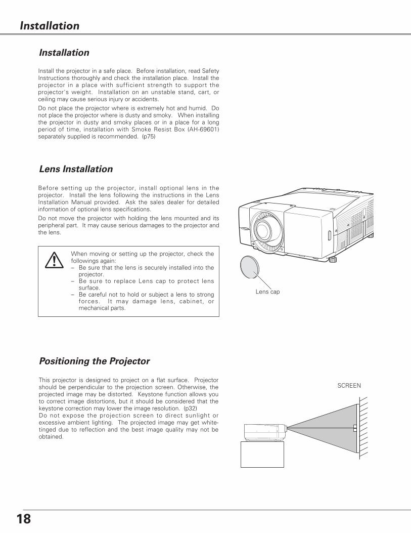
This projector is designed to project on a flat surface. Projectorshould be perpendicular to the projection screen. Otherwise, theprojected image may be distorted. Keystone function allows youto correct image distortions, but it should be considered that thekeystone correction may lower the image resolution. (p32)Do not expose the projection screen to direct sunlight orexcessive ambient lighting. The projected image may get white-tinged due to reflection and the best image quality may not beobtained.
SCREEN
Positioning the Projector
Before setting up the projector, install optional lens in theprojector. Install the lens following the instructions in the LensInstallation Manual provided. Ask the sales dealer for detailedinformation of optional lens specifications. Do not move the projector with holding the lens mounted and itsperipheral part. It may cause serious damages to the projector andthe lens.
Lens Installation
Installation
Lens cap
Installation
19
Installation
Adjustable feet
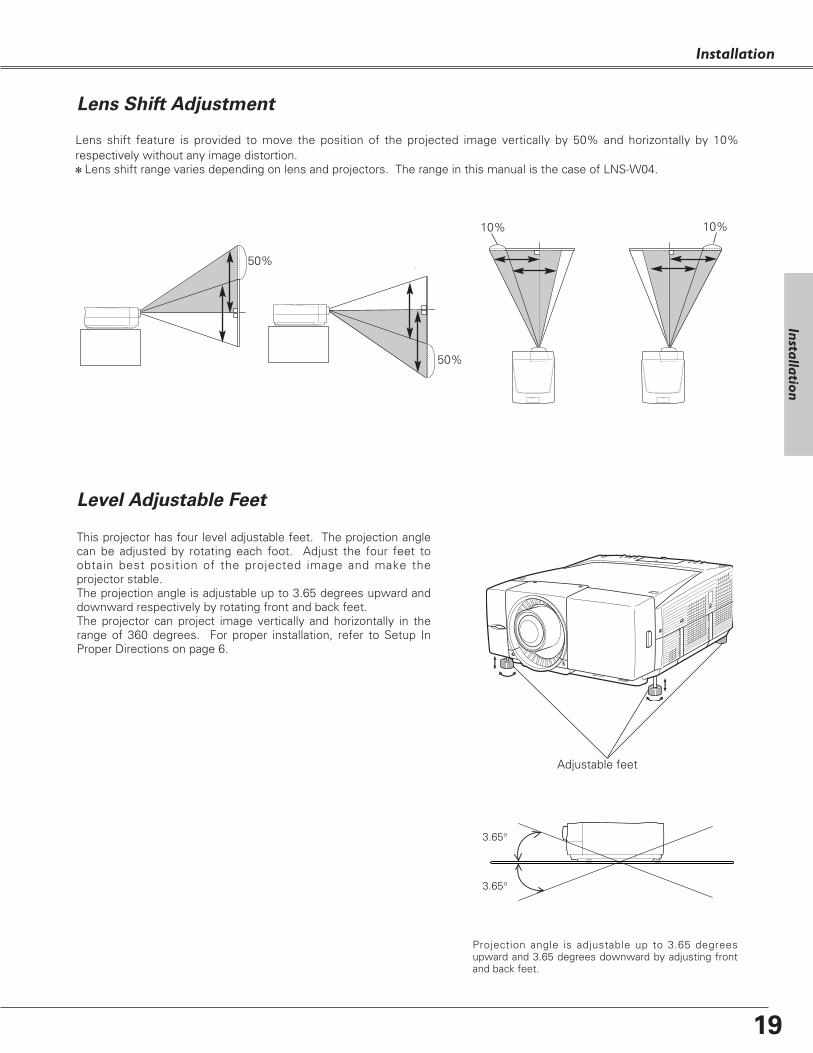
Lens shift feature is provided to move the position of the projected image vertically by 50% and horizontally by 10%respectively without any image distortion.✽ Lens shift range varies depending on lens and projectors. The range in this manual is the case of LNS-W04.
Level Adjustable Feet
This projector has four level adjustable feet. The projection anglecan be adjusted by rotating each foot. Adjust the four feet toobtain best position of the projected image and make theprojector stable. The projection angle is adjustable up to 3.65 degrees upward anddownward respectively by rotating front and back feet. The projector can project image vertically and horizontally in therange of 360 degrees. For proper installation, refer to Setup InProper Directions on page 6.
Projection angle is adjustable up to 3.65 degreesupward and 3.65 degrees downward by adjusting frontand back feet.
3.65°
3.65°
Lens Shift Adjustment
Installation
50%
50%
10% 10%
20
Installation
Connecting AC Power Cord
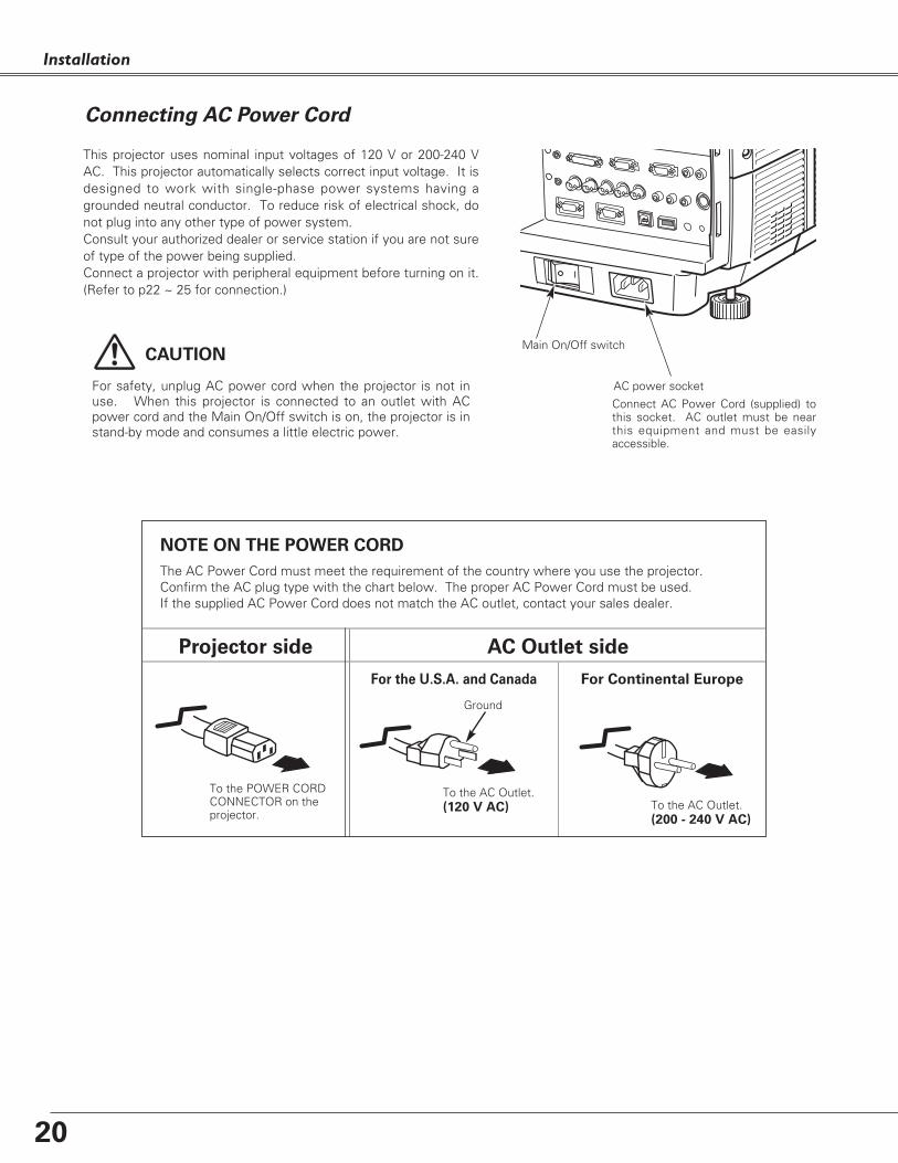
This projector uses nominal input voltages of 120 V or 200-240 VAC. This projector automatically selects correct input voltage. It isdesigned to work with single-phase power systems having agrounded neutral conductor. To reduce risk of electrical shock, donot plug into any other type of power system.Consult your authorized dealer or service station if you are not sureof type of the power being supplied.Connect a projector with peripheral equipment before turning on it.(Refer to p22 ~ 25 for connection.)
Connect AC Power Cord (supplied) tothis socket. AC outlet must be nearthis equipment and must be easilyaccessible.
Main On/Off switch
AC power socket
CAUTION
For safety, unplug AC power cord when the projector is not inuse. When this projector is connected to an outlet with ACpower cord and the Main On/Off switch is on, the projector is instand-by mode and consumes a little electric power.
To the POWER CORDCONNECTOR on theprojector.
Projector side AC Outlet side
Ground
NOTE ON THE POWER CORD
The AC Power Cord must meet the requirement of the country where you use the projector.Confirm the AC plug type with the chart below. The proper AC Power Cord must be used.If the supplied AC Power Cord does not match the AC outlet, contact your sales dealer.
To the AC Outlet.(120 V AC)
For Continental EuropeFor the U.S.A. and Canada
To the AC Outlet.(200 - 240 V AC)
21
Installation
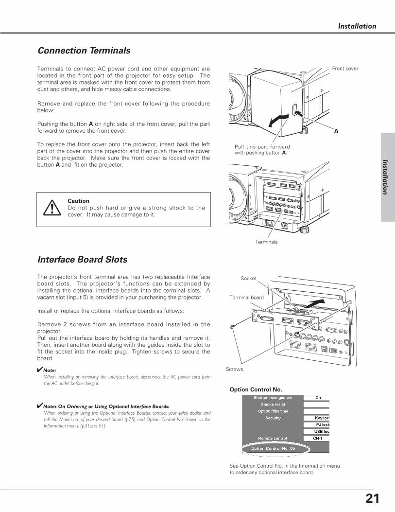
Terminals to connect AC power cord and other equipment arelocated in the front part of the projector for easy setup. Theterminal area is masked with the front cover to protect them fromdust and others, and hide messy cable connections.
The projector's front terminal area has two replaceable Interfaceboard slots. The projector's functions can be extended byinstalling the optional interface boards into the terminal slots. Avacant slot (Input 5) is provided in your purchasing the projector.
Install or replace the optional interface boards as follows:
Remove 2 screws from an interface board installed in theprojector.Pull out the interface board by holding its handles and remove it.Then, insert another board along with the guides inside the slot tofit the socket into the inside plug. Tighten screws to secure theboard.
Screws
Socket
Terminal board
✔Notes On Ordering or Using Optional Interface Boards:When ordering or using the Optional Interface Boards, contact your sales dealer andtell the Model no. of your desired board (p75) and Option Control No. shown in theInformation menu. (p31and 61)
✔Note:When installing or removing the interface board, disconnect the AC power cord fromthe AC outlet before doing it.
Remove and replace the front cover following the procedurebelow:
Pushing the button A on right side of the front cover, pull the partforward to remove the front cover.
To replace the front cover onto the projector, insert back the leftpart of the cover into the projector and then push the entire coverback the projector. Make sure the front cover is locked with thebutton A and fit on the projector.
Pull this part forwardwith pushing button A.
A
Interface Board Slots
Caution
Do not push hard or give a strong shock to thecover. It may cause damage to it.
Terminals
Front cover
Connection Terminals
Installation
Option Control No.
See Option Control No. in the Information menuto order any optional interface board.
22
Installation
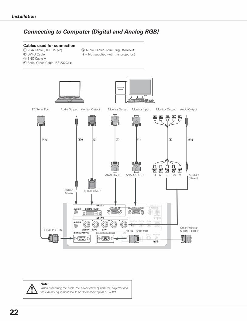
Connecting to Computer (Digital and Analog RGB)
Cables used for connectionq VGA Cable (HDB 15 pin) t Audio Cables (Mini Plug: stereo) ✽
w DVI-D Cable (✽ = Not supplied with this projector.)e BNC Cable ✽r Serial Cross Cable (RS-232C) ✽
qt✽
Monitor OutputAudio Output
DIGITAL (DVI-D)
AUDIO 2(Stereo)
q
Monitor Input
SERIAL PORT IN
Note:When connecting the cable, the power cords of both the projector andthe external equipment should be disconnected from AC outlet.
w
Monitor Output
ANALOG OUTANALOG IN
SERIAL PORT OUT
R G B H/V V
Monitor Output
e
Audio OutputPC Serial Port
Other ProjectorSERIAL PORT IN
r✽
r✽
AUDIO 1(Stereo)
t✽
23
Installation
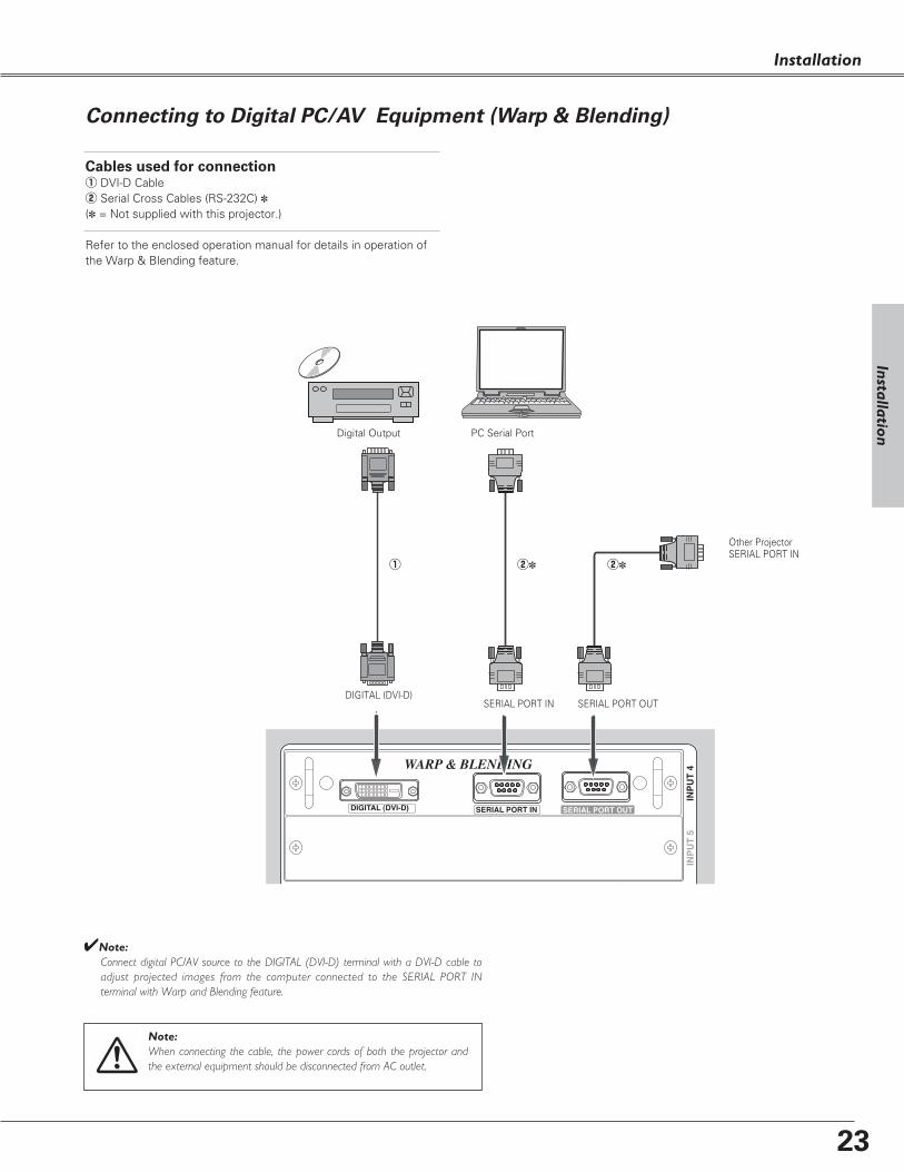
Connecting to Digital PC/AV Equipment (Warp & Blending)
Cables used for connectionq DVI-D Cable w Serial Cross Cables (RS-232C) ✽
(✽ = Not supplied with this projector.)
Refer to the enclosed operation manual for details in operation ofthe Warp & Blending feature.
PC Serial Port
Note:When connecting the cable, the power cords of both the projector andthe external equipment should be disconnected from AC outlet.
q
Digital Output
Other ProjectorSERIAL PORT IN
SERIAL PORT IN SERIAL PORT OUT
w✽
DIGITAL (DVI-D)
Installation
✔Note:Connect digital PC/AV source to the DIGITAL (DVI-D) terminal with a DVI-D cable toadjust projected images from the computer connected to the SERIAL PORT INterminal with Warp and Blending feature.
w✽
24
Installation
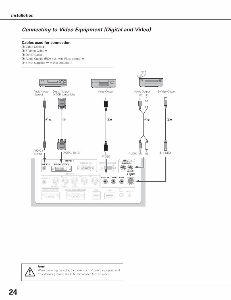
Connecting to Video Equipment (Digital and Video)
INPUT 3
VIDEO/Y Cb/Pb Cr/Pr
S-VIDEO
R-AUDIO-L
(MONO)
Cables used for connectionq Video Cable ✽w S-Video Cable ✽e DVI-D Cabler Audio Cables (RCA x 2, Mini Plug: stereo) ✽(✽ = Not supplied with this projector.)
Note:When connecting the cable, the power cords of both the projector andthe external equipment should be disconnected from AC outlet.
r✽
VIDEO
w✽q✽
S-Video OutputAudio Output
AUDIO
er ✽
DIGITAL (DVI-D)
Digital Output(HDCP compatible)
Video Output
S–VIDEOAUDIO 1(Stereo)
Audio Output(Stereo) (R) (L)
(R) (L)
25
Installation
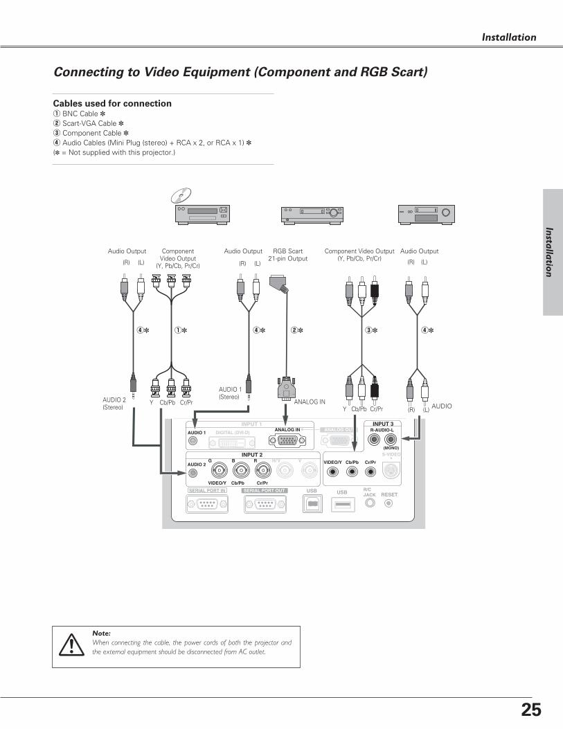
Connecting to Video Equipment (Component and RGB Scart)
INPUT 3
VIDEO/Y Cb/Pb Cr/Pr
R-AUDIO-L
(MONO)
Cables used for connectionq BNC Cable ✽
w Scart-VGA Cable ✽
e Component Cable ✽
r Audio Cables (Mini Plug (stereo) + RCA x 2, or RCA x 1) ✽(✽ = Not supplied with this projector.)
Note:When connecting the cable, the power cords of both the projector andthe external equipment should be disconnected from AC outlet.
r✽
RGB Scart21-pin Output
Audio Output
w✽r✽r✽ q✽
Component Video Output(Y, Pb/Cb, Pr/Cr)
Audio OutputComponent Video Output
(Y, Pb/Cb, Pr/Cr)
Audio Output
ANALOG INAUDIO 2(Stereo)
AUDIO 1(Stereo)
Y Cb/Pb Cr/PrY Cb/Pb Cr/Pr AUDIO
e✽
(R) (L) (R) (L)
Installation
(R) (L)
(R) (L)
26
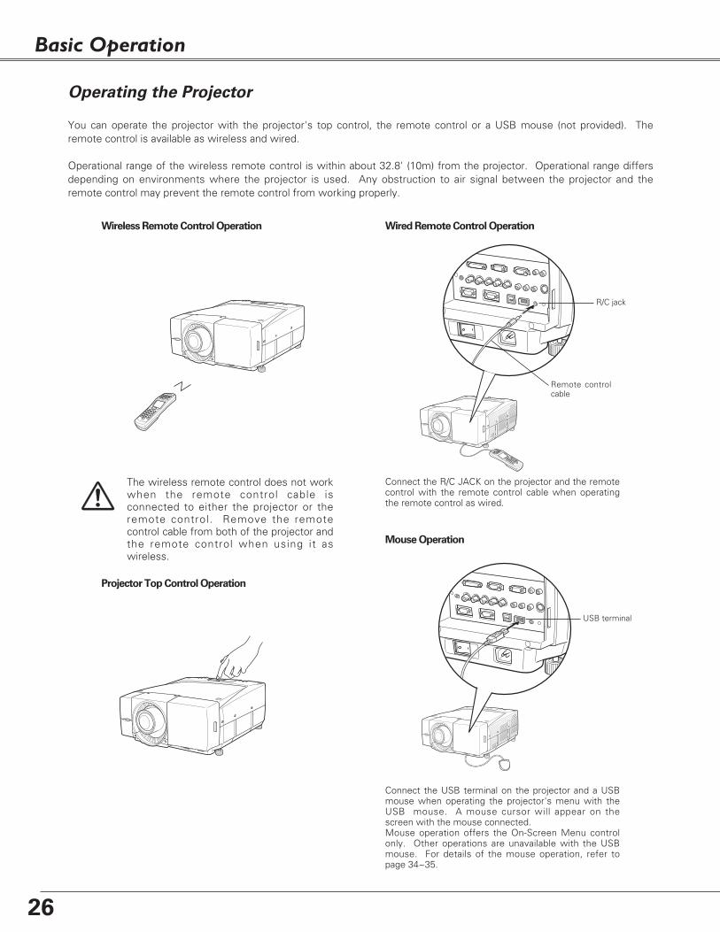
Operating the Projector
You can operate the projector with the projector's top control, the remote control or a USB mouse (not provided). Theremote control is available as wireless and wired.
Operational range of the wireless remote control is within about 32.8' (10m) from the projector. Operational range differsdepending on environments where the projector is used. Any obstruction to air signal between the projector and theremote control may prevent the remote control from working properly.
The wireless remote control does not workwhen the remote control cable isconnected to either the projector or theremote control. Remove the remotecontrol cable from both of the projector andthe remote control when using it aswireless.
Wireless Remote Control Operation
Projector Top Control Operation
Mouse Operation
Connect the R/C JACK on the projector and the remotecontrol with the remote control cable when operatingthe remote control as wired.
Connect the USB terminal on the projector and a USBmouse when operating the projector's menu with theUSB mouse. A mouse cursor will appear on thescreen with the mouse connected. Mouse operation offers the On-Screen Menu controlonly. Other operations are unavailable with the USBmouse. For details of the mouse operation, refer topage 34~35.
Wired Remote Control Operation
R/C jack
Remote controlcable
USB terminal
Basic Operation
27
Basic Operation
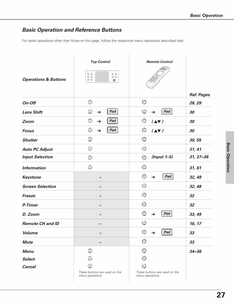
Basic Operation and Reference Buttons
Operations & Buttons
Ref. Pages
On-Off 28, 29
Lens Shift ➔ ➔ 30
Zoom ➔ ( eedd ) 30
Focus ➔ ( eedd ) 30
Shutter 30, 55
Auto PC Adjust 31, 41
Input Selection (Input 1–5) 31, 37~38
Information 31, 61
Keystone – ➔ 32, 49
Screen Selection – 32, 48
Freeze – 32
P-Timer – 32
D. Zoom – ➔ 33, 49
Remote CH and ID – 16, 17
Volume – ➔ 33
Mute – 33
Menu 34~36
Select
Cancel
Pad
Pad
Pad
Pad
Pad
PadPad
For detail operations other than those on this page, follow the respective menu operations described later.
Remote ControlTop Control
Basic O
peration
These buttons are used on themenu operations.
These buttons are used on themenu operations.
28
Basic Operation
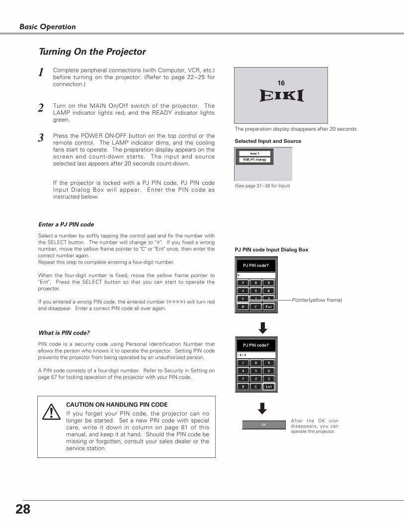
Turn on the MAIN On/Off switch of the projector. TheLAMP indicator lights red, and the READY indicator lightsgreen.
Press the POWER ON-OFF button on the top control or theremote control. The LAMP indicator dims, and the coolingfans start to operate. The preparation display appears on thescreen and count-down starts. The input and sourceselected last appears after 20 seconds count-down.
2
3
1 Complete peripheral connections (with Computer, VCR, etc.)before turning on the projector. (Refer to page 22~25 forconnection.)
Turning On the Projector
What is PIN code?
PIN code is a security code using Personal Identification Number thatallows the person who knows it to operate the projector. Setting PIN codeprevents the projector from being operated by an unauthorized person.
A PIN code consists of a four-digit number. Refer to Security in Setting onpage 57 for locking operation of the projector with your PIN code.
Pointer(yellow frame)
After the OK icondisappears, you canoperate the projector.
PJ PIN code Input Dialog Box
Enter a PJ PIN code
Select a number by softly tapping the control pad and fix the number withthe SELECT button. The number will change to "✳". If you fixed a wrongnumber, move the yellow frame pointer to "C" or "Ent" once, then enter thecorrect number again.Repeat this step to complete entering a four-digit number.
When the four-digit number is fixed, move the yellow frame pointer to"Ent". Press the SELECT button so that you can start to operate theprojector.
If you entered a wrong PIN code, the entered number (✳✳✳✳) will turn redand disappear. Enter a correct PIN code all over again.
CAUTION ON HANDLING PIN CODE
If you forget your PIN code, the projector can nolonger be started. Set a new PIN code with specialcare, write it down in column on page 81 of thismanual, and keep it at hand. Should the PIN code bemissing or forgotten, consult your sales dealer or theservice station.
16
The preparation display disappears after 20 seconds.
(See page 37~38 for Input)
Selected Input and Source
If the projector is locked with a PJ PIN code, PJ PIN codeInput Dialog Box will appear. Enter the PIN code asinstructed below.
29
Basic Operation
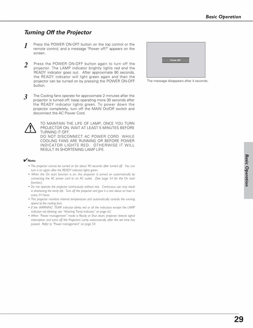
Press the POWER ON-OFF button on the top control or theremote control, and a message "Power off?" appears on thescreen.
1
2
3
Press the POWER ON-OFF button again to turn off theprojector. The LAMP indicator brightly lights red and theREADY indicator goes out. After approximate 90 seconds,the READY indicator will light green again and then theprojector can be turned on by pressing the POWER ON-OFFbutton.
The Cooling fans operate for approximate 2 minutes after theprojector is turned off; keep operating more 30 seconds afterthe READY indicator lights green. To power down theprojector completely, turn off the MAIN On/Off switch anddisconnect the AC Power Cord.
Turning Off the Projector
The message disappears after 4 seconds.
TO MAINTAIN THE LIFE OF LAMP, ONCE YOU TURNPROJECTOR ON, WAIT AT LEAST 5 MINUTES BEFORETURNING IT OFF.DO NOT DISCONNECT AC POWER CORD WHILECOOLING FANS ARE RUNNING OR BEFORE POWERINDICATOR LIGHTS RED. OTHERWISE IT WILLRESULT IN SHORTENING LAMP LIFE.
✔Note:
• The projector cannot be turned on for about 90 seconds after turned off. You canturn it on again after the READY indicator lights green.
• When the On start function is on, this projector is turned on automatically byconnecting the AC power cord to an AC outlet. (See page 54 for the On startfunction.)
• Do not operate the projector continuously without rest. Continuous use may resultin shortening the lamp life. Turn off the projector and give it a rest about an hour inevery 24 hours.
• This projector monitors internal temperature and automatically controls the runningspeed of the cooling fans.
• If the WARNING TEMP indicator blinks red or all the indicators except the LAMPindicator are blinking, see “Warning Temp Indicator” on page 62.
• When “Power management” mode is Ready or Shut down, projector detects signalinterruption and turns off the Projection Lamp automatically after the set time haspassed. Refer to “Power management” on page 54.
Basic O
peration
30
Basic Operation
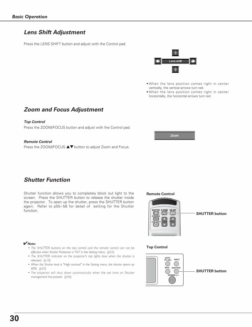
Press the ZOOM/FOCUS button and adjust with the Control pad.
Press the LENS SHIFT button and adjust with the Control pad.
Shutter Function
Shutter function allows you to completely block out light to thescreen. Press the SHUTTER button to release the shutter insidethe projector. To open up the shutter, press the SHUTTER buttonagain. Refer to p55~56 for detail of setting for the Shutterfunction.
✔Note:• The SHUTTER buttons on the top control and the remote control can not be
effective when Shutter Protection is "On" in the Setting menu. (p55)• The SHUTTER indicator on the projector's top lights blue when the shutter is
released. (p10)• When the Shutter level is "High contrast" in the Setting menu, the shutter opens up
80%. (p55)• The projector will shut down automatically when the set time on Shutter
management has passed. (p56)
MENU
C A N C E L
INFO AUTO PC
SCREENFREEZE
P-TIMERSOUND
REMOTE
VOL.
MUTE
CH
ID
L E N S S H I F T
K E Y S T O N E
S H U T T E R S H U T T E R D . Z O O MD . Z O O M
Z O O MZ O O M F O C U SF O C U S
O N - O F FO N - O F F
SHUTTER button
SHUTTER
INPUT
INFO.
AUTOPC ADJ.
POWER P
Remote Control
Top Control
Remote Control
Top Control
Press the ZOOM/FOCUS ed button to adjust Zoom and Focus.
SHUTTER button
Zoom and Focus Adjustment
Lens Shift Adjustment
• When the lens position comes right in centervertically, the vertical arrows turn red.
• When the lens position comes right in centerhorizontally, the horizontal arrows turn red.
31
Basic Operation
Information
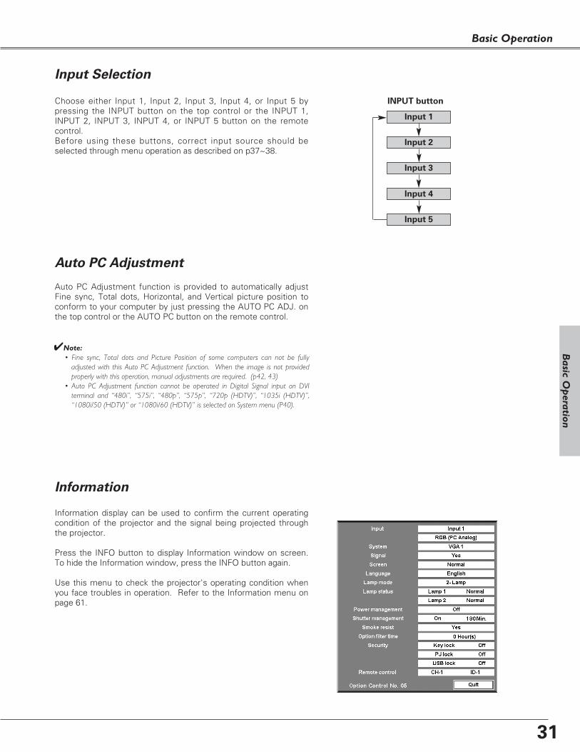
Choose either Input 1, Input 2, Input 3, Input 4, or Input 5 bypressing the INPUT button on the top control or the INPUT 1,INPUT 2, INPUT 3, INPUT 4, or INPUT 5 button on the remotecontrol.Before using these buttons, correct input source should beselected through menu operation as described on p37~38.
Input 1
Input 3
Input 2
INPUT button
Input 5
Input 4
Auto PC Adjustment function is provided to automatically adjustFine sync, Total dots, Horizontal, and Vertical picture position toconform to your computer by just pressing the AUTO PC ADJ. onthe top control or the AUTO PC button on the remote control.
Information display can be used to confirm the current operatingcondition of the projector and the signal being projected throughthe projector.
Press the INFO button to display Information window on screen.To hide the Information window, press the INFO button again.
Use this menu to check the projector's operating condition whenyou face troubles in operation. Refer to the Information menu onpage 61.
✔Note:• Fine sync, Total dots and Picture Position of some computers can not be fully
adjusted with this Auto PC Adjustment function. When the image is not providedproperly with this operation, manual adjustments are required. (p42, 43)
• Auto PC Adjustment function cannot be operated in Digital Signal input on DVIterminal and “480i”, “575i”, “480p”, “575p”, “720p (HDTV)”, “1035i (HDTV)”,“1080i/50 (HDTV)” or “1080i/60 (HDTV)” is selected on System menu (P40).
Auto PC Adjustment
Input Selection
Basic O
peration
32
Basic Operation
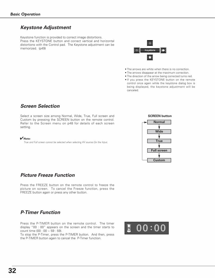
Press the FREEZE button on the remote control to freeze thepicture on screen. To cancel the Freeze function, press theFREEZE button again or press any other button.
Press the P-TIMER button on the remote control. The timerdisplay “00 : 00” appears on the screen and the timer starts tocount time (00 : 00 ~ 59 : 59). To stop the P-Timer, press the P-TIMER button. And then, pressthe P-TIMER button again to cancel the P-Timer function.
P-Timer Function
SCREEN button
Normal
Wide
True
Full screen
Select a screen size among Normal, Wide, True, Full screen andCustom by pressing the SCREEN button on the remote control.Refer to the Screen menu on p48 for details of each screensetting.
Keystone function is provided to correct image distortions.Press the KEYSTONE button and correct vertical and horizontaldistortions with the Control pad. The Keystone adjustment can bememorized. (p49)
Custom
• The arrows are white when there is no correction.• The arrows disappear at the maximum correction.• The direction of the arrow being corrected turns red.• If you press the KEYSTONE button on the remote
control once again while the keystone dialog box isbeing displayed, the keystone adjustment will becanceled.
Picture Freeze Function
Screen Selection
Keystone Adjustment
✔Note:True and Full screen cannot be selected when selecting AV sources for the Input.
33
Basic Operation
Volume
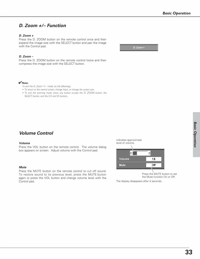
Press the VOL button on the remote control. The volume dialogbox appears on screen. Adjust volume with the Control pad.
Mute
Press the MUTE button on the remote control to cut off sound.To restore sound to its previous level, press the MUTE buttonagain or press the VOL button and change volume level with theControl pad.
indicates approximatelevel of volume.
Press the MUTE button to setthe Mute function On or Off.
The display disappears after 4 seconds.
Volume Control
Press the D. ZOOM button on the remote control once and thenexpand the image size with the SELECT button and pan the imagewith the Control pad.
D. Zoom –
D. Zoom +
Press the D. ZOOM button on the remote control twice and thencompress the image size with the SELECT button.
✔Note:To exit the D. Zoom +/– mode, try the followings:• To return to the normal screen, change Input, or change the screen size.• To exit the panning mode, press any button except the D. ZOOM button, the
SELECT button, and the CH and ID buttons.
D. Zoom +/– Function
Basic O
peration
34
LENSSHIFT MENU
CANCEL
SELECT
ZOOM
FOCUS
Basic Operation
How to Operate the On-Screen Menu
The projector can be adjusted or set via the On-Screen Menu.Refer to the following pages for respective adjustment and settingprocedure.
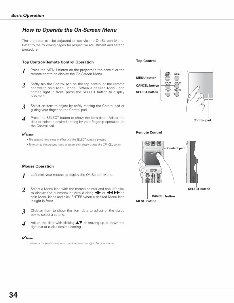
Softly tap the Control pad on the top control or the remotecontrol to spin Menu icons. When a desired Menu iconcomes right in front, press the SELECT button to displaySub-menu.
Select an item to adjust by softly tapping the Control pad orgliding your finger on the Control pad.
Press the MENU button on the projector's top control or theremote control to display the On-Screen Menu.
✔Note:
• The selected item is not in effect until the SELECT button is pressed.
• To return to the previous menu or cancel the selection, press the CANCEL button.
1
2
3
MENUMENU
C A N C E LC A N C E L
INFOINFO AUTO PCAUTO PC
SCREENSCREENFREEZE
P-TIMERP-TIMERSOUNDSOUND
REMOTE
VOL.VOL.
MUTEMUTE
CH
ID
INPUT 1
L E N S S H I F T
K E Y S T O N E
S H U T T E R D . Z O O M
Z O O MZ O O M F O C U SF O C U S
O N - O F F
Control pad
Remote Control
Press the SELECT button to show the item data. Adjust thedata or select a desired setting by your fingertip operation onthe Control pad.
4
Top Control/Remote Control Operation
Mouse Operation
Select a Menu icon with the mouse pointer and one left clickto display the submenu or with clicking 78 or 77 88 tospin Menu icons and click ENTER when a desired Menu iconis right in front.
Click an item to show the item data to adjust or the dialogbox to select a setting.
Left click your mouse to display the On-Screen Menu.1
2
3
Adjust the data with clicking ed or moving up or down theright bar or click a desired setting.4
✔Note:
To return to the previous menu or cancel the selection, right click your mouse.
Top Control
MENU button
CANCEL button
SELECT button
Control pad
MENU button
CANCEL button
SELECT button
35
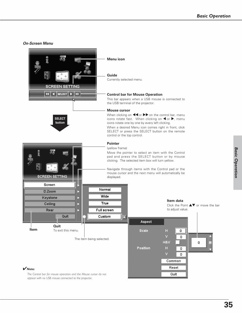
Basic Operation
Menu icon
Pointer
(yellow frame)Move the pointer to select an item with the Controlpad and press the SELECT button or by mouseclicking. The selected item box will turn yellow.
Item
SELECT
button
Item data
Click the Point ed or move the barto adjust value.
Control bar for Mouse Operation
This bar appears when a USB mouse is connected tothe USB terminal of the projector.
Guide
Currently selected menu.
On-Screen Menu
Mouse cursor
When clicking on 77 or 88 on the control bar, menuicons rotate fast. When clicking on 7 or 8, menuicons rotate one by one by every left clicking.When a desired Menu icon comes right in front, clickSELECT or press the SELECT button on the remotecontrol or the top control.
The item being selected.
Quit
To exit this menu.
Navigate through items with the Control pad or themouse cursor and the next menu will automatically bedisplayed.
✔Note:
The Control bar for mouse operation and the Mouse cursor do notappear with no USB mouse connected to the projector.
Basic O
peration
36
Basic Operation
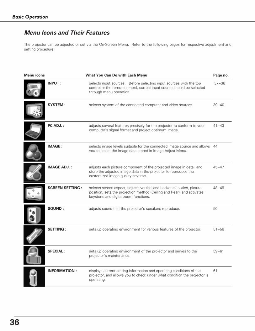
INPUT : selects input sources. Before selecting input sources with the topcontrol or the remote control, correct input source should be selectedthrough menu operation.
SYSTEM : selects system of the connected computer and video sources.
IMAGE : selects image levels suitable for the connected image source and allowsyou to select the image data stored in Image Adjust Menu.
IMAGE ADJ. : adjusts each picture component of the projected image in detail andstore the adjusted image data in the projector to reproduce thecustomized image quality anytime.
SCREEN SETTING : selects screen aspect, adjusts vertical and horizontal scales, pictureposition, sets the projection method (Ceiling and Rear), and activateskeystone and digital zoom functions.
SETTING : sets up operating environment for various features of the projector.
PC ADJ. : adjusts several features precisely for the projector to conform to yourcomputer's signal format and project optimum image.
SOUND : adjusts sound that the projector's speakers reproduce.
SPECIAL : sets up operating environment of the projector and serves to theprojector's maintenance.
INFORMATION : displays current setting information and operating conditions of theprojector, and allows you to check under what condition the projector isoperating.
Menu Icons and Their Features
The projector can be adjusted or set via the On-Screen Menu. Refer to the following pages for respective adjustment andsetting procedure.
Page no.
37~38
39~40
41~43
44
45~47
48~49
50
51~58
59~61
61
Menu icons What You Can Do with Each Menu
37
Input
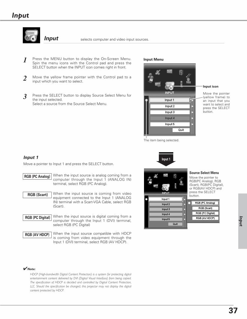
Press the MENU button to display the On-Screen Menu.Spin the menu icons with the Control pad and press theSELECT button when the INPUT icon comes right in front.
1
Move the yellow frame pointer with the Control pad to ainput which you want to select.2
Input 1
Move a pointer to Input 1 and press the SELECT button.
When the input source is analog coming from acomputer through the Input 1 (ANALOG IN)terminal, select RGB (PC Analog).
RGB (PC Analog)
When the input source is digital coming from acomputer through the Input 1 (DVI) terminal,select RGB (PC Digital)
RGB (PC Digital)
RGB (Scart)
When the input source compatible with HDCPis coming from video equipment through theInput 1 (DVI) terminal, select RGB (AV HDCP).
RGB (AV HDCP)
✔Note:
HDCP (High-bandwidth Digital Content Protection) is a system for protecting digitalentertainment content delivered by DVI (Digital Visual Interface) from being copied.The specification of HDCP is decided and controlled by Digital Content Protection,LLC. Should the specification be changed, this projector may not display the digitalcontent protected by HDCP.
When the input source is coming from videoequipment connected to the Input 1 (ANALOGIN) terminal with a Scart-VGA Cable, select RGB(Scart).
selects computer and video input sources.
Input 1
Input Menu
Move the pointer toRGB(PC Analog), RGB(Scart), RGB(PC Digital),or RGB(AV HDCP) andpress the SELECTbutton.
Source Select Menu
Input icon
Move the pointer(yellow frame) toan input that youwant to select andpress the SELECTbutton.
The item being selected.
Press the SELECT button to display Source Select Menu forthe input selected. Select a source from the Source Select Menu.
3
Input
Input
38
Input
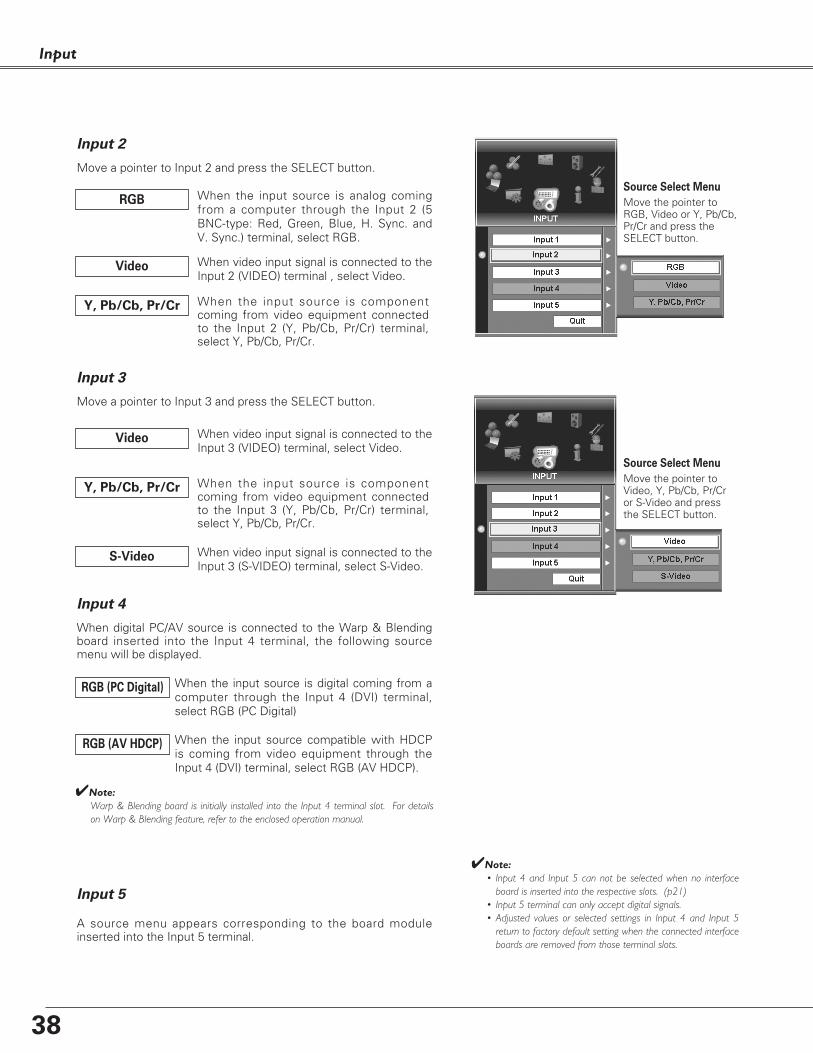
Y, Pb/Cb, Pr/Cr When the input source is componentcoming from video equipment connectedto the Input 3 (Y, Pb/Cb, Pr/Cr) terminal,select Y, Pb/Cb, Pr/Cr.
Input 3
Move a pointer to Input 3 and press the SELECT button.
Input 4
When digital PC/AV source is connected to the Warp & Blendingboard inserted into the Input 4 terminal, the following sourcemenu will be displayed.
Input 5
When video input signal is connected to theInput 3 (VIDEO) terminal, select Video.
Video
When video input signal is connected to theInput 3 (S-VIDEO) terminal, select S-Video.
S-Video
When the input source is analog comingfrom a computer through the Input 2 (5BNC-type: Red, Green, Blue, H. Sync. andV. Sync.) terminal, select RGB.
RGB
When video input signal is connected to theInput 2 (VIDEO) terminal , select Video.
Video
Input 2
Move a pointer to Input 2 and press the SELECT button.
Y, Pb/Cb, Pr/Cr When the input source is componentcoming from video equipment connectedto the Input 2 (Y, Pb/Cb, Pr/Cr) terminal,select Y, Pb/Cb, Pr/Cr.
Move the pointer toRGB, Video or Y, Pb/Cb,Pr/Cr and press theSELECT button.
Source Select Menu
Move the pointer toVideo, Y, Pb/Cb, Pr/Cror S-Video and pressthe SELECT button.
Source Select Menu
A source menu appears corresponding to the board moduleinserted into the Input 5 terminal.
✔Note:• Input 4 and Input 5 can not be selected when no interface
board is inserted into the respective slots. (p21)• Input 5 terminal can only accept digital signals.• Adjusted values or selected settings in Input 4 and Input 5
return to factory default setting when the connected interfaceboards are removed from those terminal slots.
When the input source is digital coming from acomputer through the Input 4 (DVI) terminal,select RGB (PC Digital)
RGB (PC Digital)
When the input source compatible with HDCPis coming from video equipment through theInput 4 (DVI) terminal, select RGB (AV HDCP).
RGB (AV HDCP)
✔Note:Warp & Blending board is initially installed into the Input 4 terminal slot. For detailson Warp & Blending feature, refer to the enclosed operation manual.
39
PC System Menu
1
2
Custom Mode(1~50) set in thePC Adjust Menu.(p42, 43)
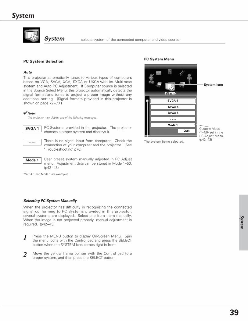
This projector automatically tunes to various types of computersbased on VGA, SVGA, XGA, SXGA or UXGA with its Multi-scansystem and Auto PC Adjustment. If Computer source is selectedin the Source Select Menu, this projector automatically detects thesignal format and tunes to project a proper image without anyadditional setting. (Signal formats provided in this projector isshown on page 72~73 )
When the projector has difficulty in recognizing the connectedsignal conforming to PC Systems provided in this projector,several systems are displayed. Select one from them manually.When the image is not projected properly, manual adjustment isrequired. (p42~43)
There is no signal input from computer. Check theconnection of your computer and the projector. (See" Troubleshooting" p70)
-----
✔Note:The projector may display one of the following messages.
User preset system manually adjusted in PC Adjustmenu. Adjustment data can be stored in Mode 1–50.(p42~43)
Mode 1
*SVGA 1 and Mode 1 are examples.
selects system of the connected computer and video source.
PC Systems provided in the projector. The projectorchooses a proper system and displays it.
SVGA 1
Press the MENU button to display On-Screen Menu. Spinthe menu icons with the Control pad and press the SELECTbutton when the SYSTEM icon comes right in front.
Move the yellow frame pointer with the Control pad to aproper system, and then press the SELECT button.
The system being selected.
PC System Selection
Selecting PC System Manually
Auto
System
System
System
System icon
40
System
AV System Menu (Video or S-Video)
AV System Menu (Component)
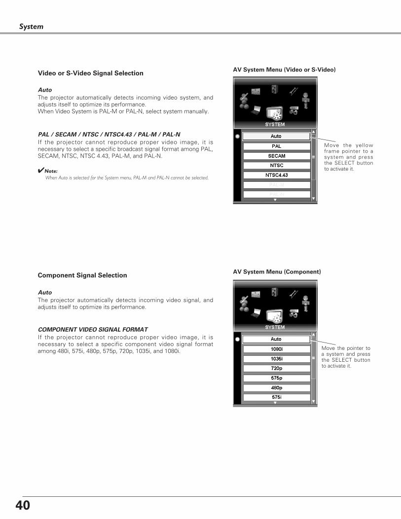
If the projector cannot reproduce proper video image, it isnecessary to select a specific broadcast signal format among PAL,SECAM, NTSC, NTSC 4.43, PAL-M, and PAL-N.
Move the yellowframe pointer to asystem and pressthe SELECT buttonto activate it.
PAL / SECAM / NTSC / NTSC4.43 / PAL-M / PAL-N
The projector automatically detects incoming video signal, andadjusts itself to optimize its performance.
If the projector cannot reproduce proper video image, it isnecessary to select a specific component video signal formatamong 480i, 575i, 480p, 575p, 720p, 1035i, and 1080i.
Auto
COMPONENT VIDEO SIGNAL FORMAT
Component Signal Selection
The projector automatically detects incoming video system, andadjusts itself to optimize its performance.When Video System is PAL-M or PAL-N, select system manually.
Auto
Move the pointer toa system and pressthe SELECT buttonto activate it.
✔Note:When Auto is selected for the System menu, PAL-M and PAL-N cannot be selected.
Video or S-Video Signal Selection
41
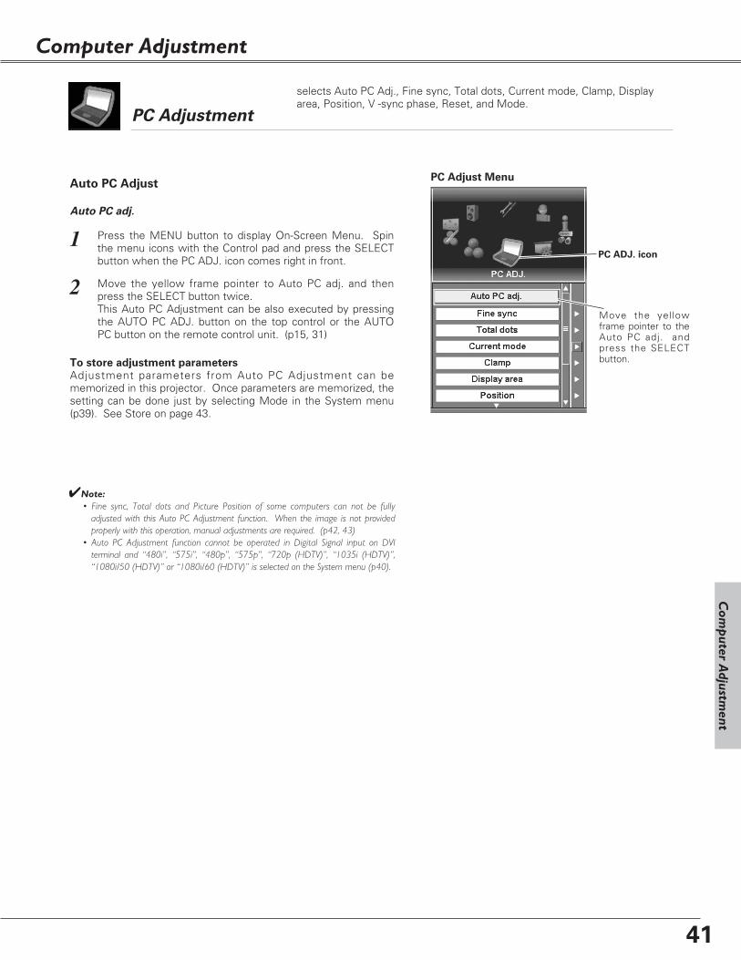
Move the yellowframe pointer to theAuto PC adj. andpress the SELECTbutton.
PC Adjust Menu
PC ADJ. icon
To store adjustment parameters
Adjustment parameters from Auto PC Adjustment can bememorized in this projector. Once parameters are memorized, thesetting can be done just by selecting Mode in the System menu(p39). See Store on page 43.
✔Note:• Fine sync, Total dots and Picture Position of some computers can not be fully
adjusted with this Auto PC Adjustment function. When the image is not providedproperly with this operation, manual adjustments are required. (p42, 43)
• Auto PC Adjustment function cannot be operated in Digital Signal input on DVIterminal and “480i”, “575i”, “480p”, “575p”, “720p (HDTV)”, “1035i (HDTV)”,“1080i/50 (HDTV)” or “1080i/60 (HDTV)” is selected on the System menu (p40).
1
2 Move the yellow frame pointer to Auto PC adj. and thenpress the SELECT button twice.This Auto PC Adjustment can be also executed by pressingthe AUTO PC ADJ. button on the top control or the AUTOPC button on the remote control unit. (p15, 31)
Auto PC adj.
selects Auto PC Adj., Fine sync, Total dots, Current mode, Clamp, Displayarea, Position, V -sync phase, Reset, and Mode.
Press the MENU button to display On-Screen Menu. Spinthe menu icons with the Control pad and press the SELECTbutton when the PC ADJ. icon comes right in front.
Auto PC Adjust
PC Adjustment
Computer AdjustmentC
omp
uter Adjustm
ent
42
Computer Adjustment
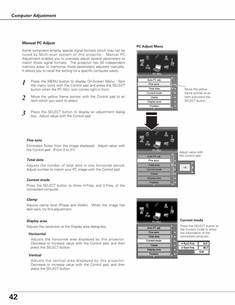
Press the MENU button to display On-Screen Menu. Spinthe menu icons with the Control pad and press the SELECTbutton when the PC ADJ. icon comes right in front.
1
2Move the yellowframe pointer to anitem and press theSELECT button.
PC Adjust Menu
Adjust value withthe Control pad.
Some computers employ special signal formats which may not betuned by Multi-scan system of this projector. Manual PCAdjustment enables you to precisely adjust several parameters tomatch those signal formats. The projector has 50 independentmemory areas to memorize those parameters adjusted manually.It allows you to recall the setting for a specific computer easily.
Eliminates flicker from the image displayed. Adjust value withthe Control pad. (From 0 to 31)
Fine sync
Adjusts the number of total dots in one horizontal period.Adjust number to match your PC image with the Control pad.
Total dots
Press the SELECT button to show H-Freq. and V-Freq. of theconnected computer.
Current mode
Adjusts clamp level (Phase and Width). When the image hasdark bars, try this adjustment.
Clamp
Adjusts the resolution at the Display area dialog box.
Horizontal
Adjusts the horizontal area displayed by this projector.Decrease or increase value with the Control pad, and thenpress the SELECT button.
Vertical
Adjusts the vertical area displayed by this projector.Decrease or increase value with the Control pad, and thenpress the SELECT button.
Display area
Press the SELECT button atthe Current mode to showthe information of theconnected computer.
Current mode
Manual PC Adjust
Move the yellow frame pointer with the Control pad to anitem which you want to select.
Press the SELECT button to display an adjustment dialogbox. Adjust value with the Control pad.3
43
Computer Adjustment
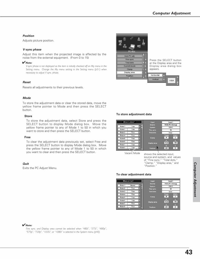
Adjust this item when the projected image is affected by thenoise from the external equipment. (From 0 to 15)
V-sync phase
Reset
Mode
Exits the PC Adjust Menu.Quit
Resets all adjustments to their previous levels.
Vacant Mode shows the selected input,source and system, and valuesof “Fine sync,” “Total dots,”“Clamp,” “Display area,” and“Position.”
To store adjustment data
To clear adjustment data
Press the SELECT buttonat the Display area and theDisplay area dialog boxappears.
✔Note:Fine sync. and Display area cannot be selected when “480i”, “575i”, “480p”,“575p”, “720p”, “1035i”, or “1080i” is selected in the System menu (p40).
Adjusts picture position.
Position
To store the adjustment data or clear the stored data, move theyellow frame pointer to Mode and then press the SELECTbutton.
Store
To store the adjustment data, select Store and press theSELECT button to display Mode dialog box. Move theyellow frame pointer to any of Mode 1 to 50 in which youwant to store and then press the SELECT button.
Free
To clear the adjustment data previously set, select Free andpress the SELECT button to display Mode dialog box. Movethe yellow frame pointer to any of Mode 1 to 50 in whichyou want to clear and then press the SELECT button.
Com
puter A
djustment
✔Note:V-sync phase is not displayed as the item is initially checked off on My menu in theSetting menu. Change the My menu setting in the Setting menu (p51) whennecessary to adjust V sync. phase.
44
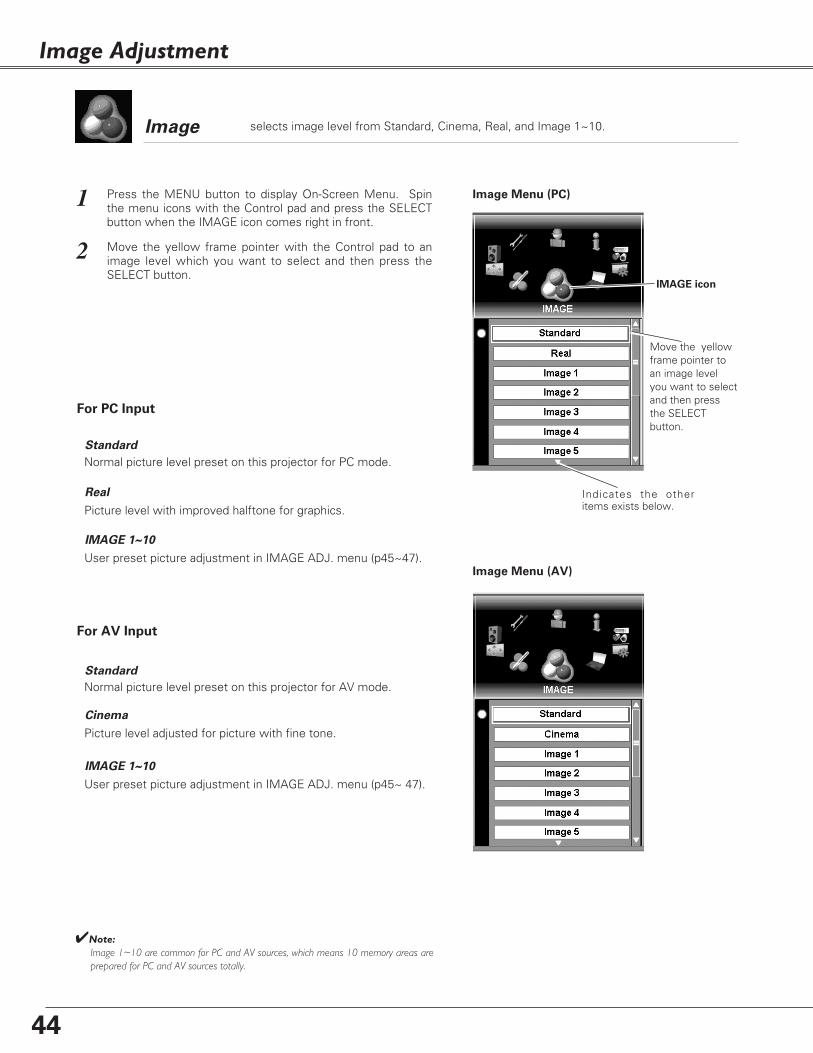
Image Menu (PC)
Move the yellowframe pointer toan image levelyou want to selectand then pressthe SELECTbutton.
1
Normal picture level preset on this projector for AV mode.Standard
Picture level with improved halftone for graphics.
Real
Normal picture level preset on this projector for PC mode.Standard
Picture level adjusted for picture with fine tone.
Cinema
User preset picture adjustment in IMAGE ADJ. menu (p45~ 47).
IMAGE 1~10
2
selects image level from Standard, Cinema, Real, and Image 1~10.
Press the MENU button to display On-Screen Menu. Spinthe menu icons with the Control pad and press the SELECTbutton when the IMAGE icon comes right in front.
Move the yellow frame pointer with the Control pad to animage level which you want to select and then press theSELECT button.
Image Menu (AV)
For PC Input
For AV Input
User preset picture adjustment in IMAGE ADJ. menu (p45~47).
IMAGE 1~10
✔Note:Image 1~10 are common for PC and AV sources, which means 10 memory areas areprepared for PC and AV sources totally.
Image
Image Adjustment
IMAGE icon
Indicates the otheritems exists below.
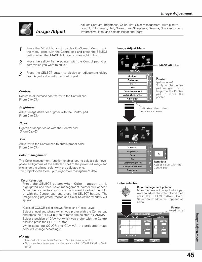
45
Image Adjustment
1
2
Decrease or increase contrast with the Control pad. (From 0 to 63.)
Adjust image darker or brighter with the Control pad. (From 0 to 63.)
Contrast
Brightness
Lighten or deeper color with the Control pad. (From 0 to 63.)
Adjust with the Control pad to obtain proper color. (From 0 to 63.)
Color
Tint
Image Adjust
Image Adjust Menu
Color management
The Color management function enables you to adjust color level,phase and gamma of the selected spot of the projected image andexchange the original color with the adjusted one.The projector can store up to eight color management data.
adjusts Contrast, Brightness, Color, Tint, Color management, Auto picturecontrol, Color temp., Red, Green, Blue, Sharpness, Gamma, Noise reduction,Progressive, Film, and selects Reset and Store.
Pointer (yellow frame)Softly tap the Controlpad or grind yourfinger on the Controlpad to move thepointer.
Indicates the otheritems exists below.
Item dataAdjust value with theControl pad.
✔Note:• Color and Tint cannot be displayed when PC input source is selected.• Tint cannot be adjusted when the video system is PAL, SECAM, PAL-M or PAL-N.
(p40)
Press the MENU button to display On-Screen Menu. Spinthe menu icons with the Control pad and press the SELECTbutton when the IMAGE ADJ. icon comes right in front.
Move the yellow frame pointer with the Control pad to anitem which you want to adjust.
Press the SELECT button to display an adjustment dialogbox. Adjust value with the Control pad.3
Color selection Press the SELECT button when Color management ishighlighted and then Color management pointer will appear.Move the pointer to a spot which you want to adjust the colorof with the Control pad, and press the SELECT button. Theimage being projected freezes and Color Selection window willappear.
X-axis of COLOR pallet shows Phase and Y-axis, Level.Select a level and phase which you prefer with the Control padand press the SELECT button to move the pointer to GAMMA.Select a position of GAMMA which you prefer with the Controlpad and press the SELECT button.While adjusting COLOR and GAMMA, the projected imagecolor will change accordingly.
Color management pointer Move the pointer to a spot which youwant to adjust the color of and thenpress the SELECT button. ColorSelection window wil l appear asbelow.
Color selection
Image A
djustment
IMAGE ADJ. icon
Pointer (red frame)
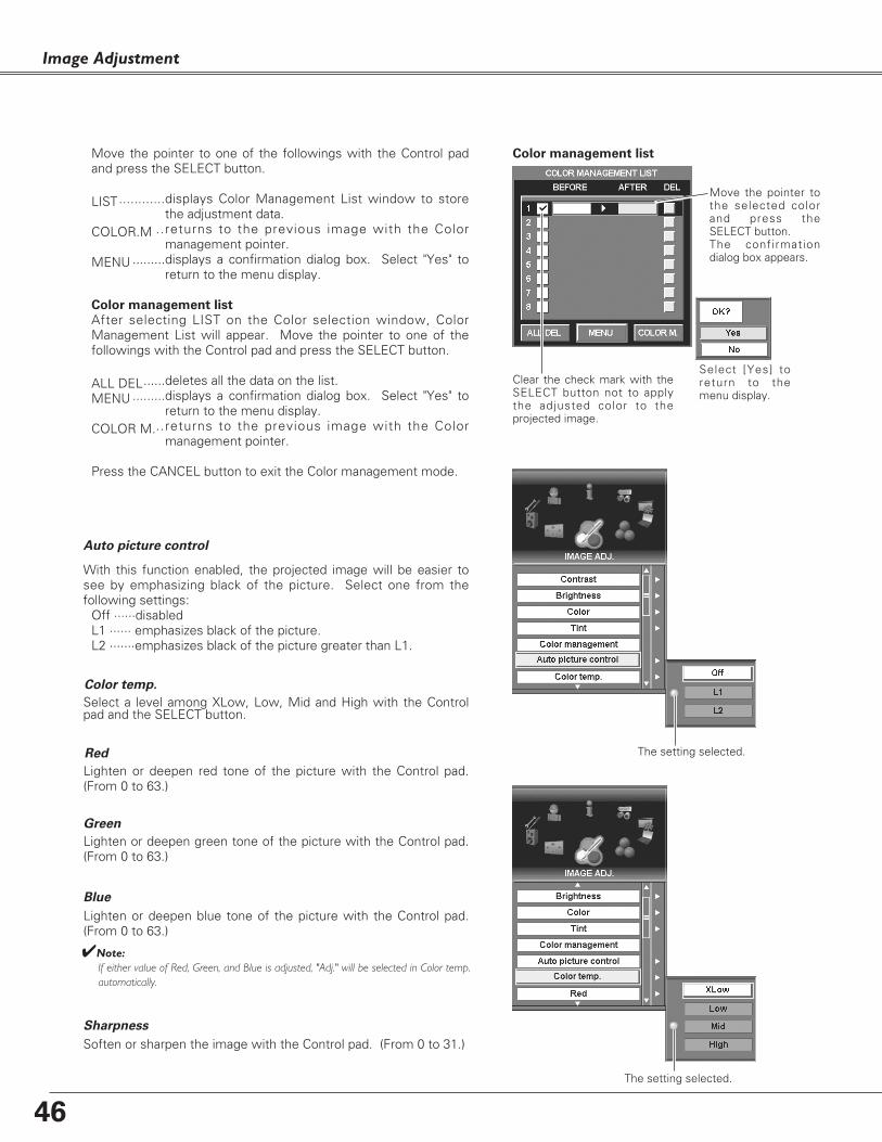
46
Image Adjustment
Move the pointer to one of the followings with the Control padand press the SELECT button.
LIST............displays Color Management List window to storethe adjustment data.
COLOR.M ..returns to the previous image with the Colormanagement pointer.
MENU .........displays a confirmation dialog box. Select "Yes" toreturn to the menu display.
Color management list
After selecting LIST on the Color selection window, ColorManagement List will appear. Move the pointer to one of thefollowings with the Control pad and press the SELECT button.
ALL DEL......deletes all the data on the list.MENU .........displays a confirmation dialog box. Select "Yes" to
return to the menu display.COLOR M...returns to the previous image with the Color
management pointer.
Press the CANCEL button to exit the Color management mode.
Move the pointer tothe selected colorand press theSELECT button.The confirmationdialog box appears.
Color management list
Clear the check mark with theSELECT button not to applythe adjusted color to theprojected image.
Soften or sharpen the image with the Control pad. (From 0 to 31.)Sharpness
Lighten or deepen green tone of the picture with the Control pad.(From 0 to 63.)
Green
Lighten or deepen blue tone of the picture with the Control pad.(From 0 to 63.)
Blue
Auto picture control
With this function enabled, the projected image will be easier tosee by emphasizing black of the picture. Select one from thefollowing settings:
Off ······disabledL1 ······ emphasizes black of the picture.L2 ·······emphasizes black of the picture greater than L1.
Lighten or deepen red tone of the picture with the Control pad.(From 0 to 63.)
Red
Color temp.
Select a level among XLow, Low, Mid and High with the Controlpad and the SELECT button.
Select [Yes] toreturn to themenu display.
The setting selected.
The setting selected.
✔Note:If either value of Red, Green, and Blue is adjusted, "Adj." will be selected in Color temp.automatically.
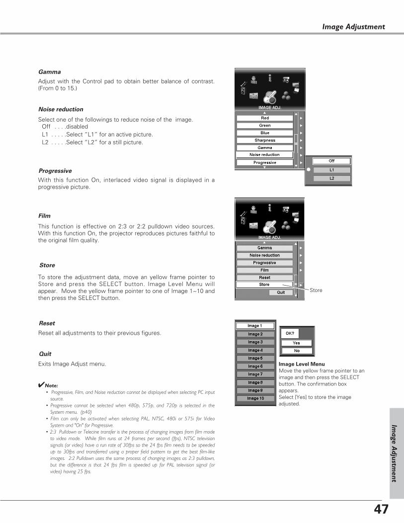
47
Image Adjustment
Reset all adjustments to their previous figures.
Reset
Store
Exits Image Adjust menu.
Quit
To store the adjustment data, move an yellow frame pointer toStore and press the SELECT button. Image Level Menu willappear. Move the yellow frame pointer to one of Image 1~10 andthen press the SELECT button.
With this function On, interlaced video signal is displayed in aprogressive picture.
Progressive
This function is effective on 2:3 or 2:2 pulldown video sources.With this function On, the projector reproduces pictures faithful tothe original film quality.
Film
✔Note:• Progressive, Film, and Noise reduction cannot be displayed when selecting PC input
source.• Progressive cannot be selected when 480p, 575p, and 720p is selected in the
System menu. (p40)• Film can only be activated when selecting PAL, NTSC, 480i or 575i for Video
System and "On" for Progressive. • 2:3 Pulldown or Telecine transfer is the process of changing images from film mode
to video mode. While film runs at 24 frames per second (fps), NTSC televisionsignals (or video) have a run rate of 30fps so the 24 fps film needs to be speededup to 30fps and transferred using a proper field pattern to get the best film-likeimages. 2:2 Pulldown uses the same process of changing images as 2:3 pulldown,but the difference is that 24 fps film is speeded up for PAL television signal (orvideo) having 25 fps.
Store
Image Level Menu
Move the yellow frame pointer to animage and then press the SELECTbutton. The confirmation boxappears.Select [Yes] to store the imageadjusted.
Select one of the followings to reduce noise of the image.Off . . . .disabledL1 . . . . .Select “L1” for an active picture.L2 . . . . .Select “L2” for a still picture.
Noise reduction
Adjust with the Control pad to obtain better balance of contrast.(From 0 to 15.)
Gamma
Image A
djustment
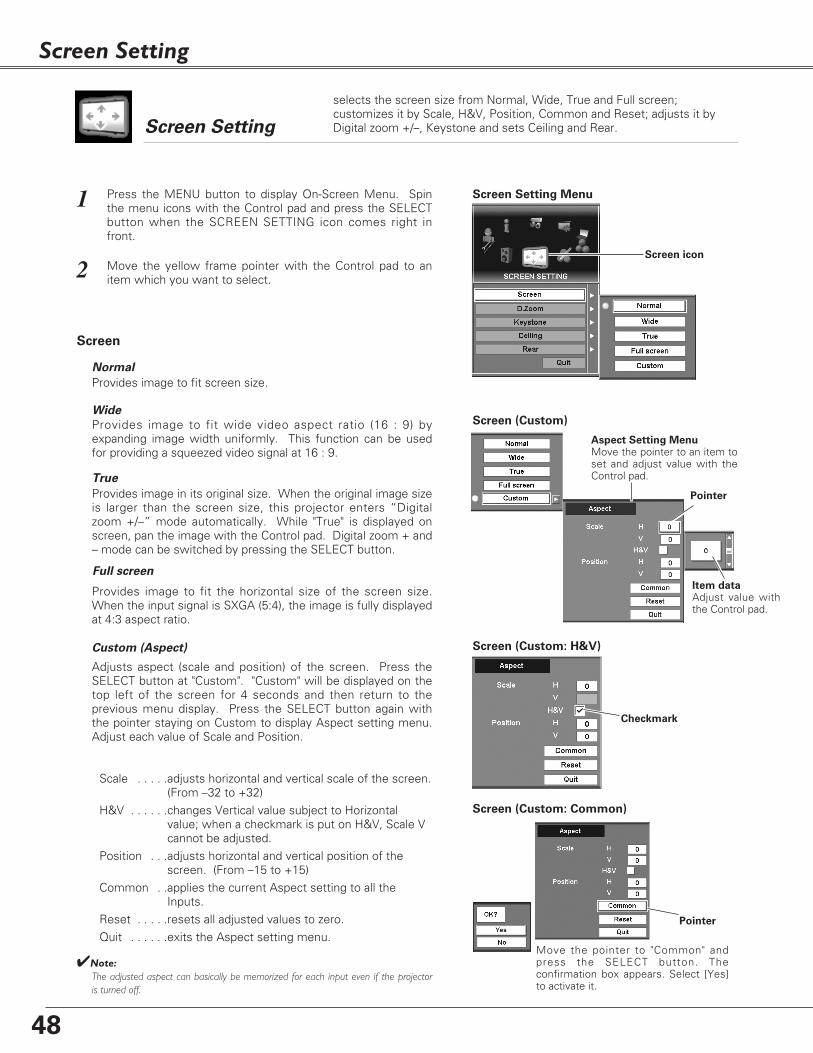
48
Provides image to fit the horizontal size of the screen size.When the input signal is SXGA (5:4), the image is fully displayedat 4:3 aspect ratio.
Full screen
Adjusts aspect (scale and position) of the screen. Press theSELECT button at "Custom". "Custom" will be displayed on thetop left of the screen for 4 seconds and then return to theprevious menu display. Press the SELECT button again withthe pointer staying on Custom to display Aspect setting menu.Adjust each value of Scale and Position.
Scale . . . . .adjusts horizontal and vertical scale of the screen.(From –32 to +32)
H&V . . . . . .changes Vertical value subject to Horizontalvalue; when a checkmark is put on H&V, Scale Vcannot be adjusted.
Position . . .adjusts horizontal and vertical position of thescreen. (From –15 to +15)
Common . .applies the current Aspect setting to all theInputs.
Reset . . . . .resets all adjusted values to zero. Quit . . . . . .exits the Aspect setting menu.
1
2
Screen Setting Menu
Wide
Provides image to fit screen size.Normal
True
Custom (Aspect)
Provides image in its original size. When the original image sizeis larger than the screen size, this projector enters “Digitalzoom +/–” mode automatically. While "True" is displayed onscreen, pan the image with the Control pad. Digital zoom + and– mode can be switched by pressing the SELECT button.
Provides image to fit wide video aspect ratio (16 : 9) byexpanding image width uniformly. This function can be usedfor providing a squeezed video signal at 16 : 9.
selects the screen size from Normal, Wide, True and Full screen;customizes it by Scale, H&V, Position, Common and Reset; adjusts it byDigital zoom +/–, Keystone and sets Ceiling and Rear.
Screen
Press the MENU button to display On-Screen Menu. Spinthe menu icons with the Control pad and press the SELECTbutton when the SCREEN SETTING icon comes right infront.
Move the yellow frame pointer with the Control pad to anitem which you want to select.
Screen (Custom: H&V)
Screen Setting
Screen Setting
Screen (Custom)
Item dataAdjust value withthe Control pad.
Screen (Custom: Common)
Screen icon
Aspect Setting MenuMove the pointer to an item toset and adjust value with theControl pad.
Pointer
Checkmark
Move the pointer to "Common" andpress the SELECT button. Theconfirmation box appears. Select [Yes]to activate it.
Pointer
✔Note:The adjusted aspect can basically be memorized for each input even if the projectoris turned off.
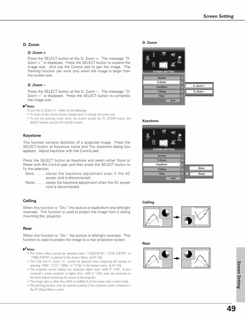
49
Screen Setting
Press the SELECT button at the D. Zoom –. The message “D.Zoom –” is displayed. Press the SELECT button to compressthe image size.
D. Zoom –
Ceiling
Rear
When this function is “On,” the picture is top/bottom and left/rightreversed. This function is used to project the image from a ceilingmounting the projector.
When this function is “On,” the picture is left/right reversed. Thisfunction is used to project the image to a rear projection screen.
Press the SELECT button at the D. Zoom +. The message “D.Zoom +” is displayed. Press the SELECT button to expand theimage size. And use the Control pad to pan the image. ThePanning function can work only when the image is larger thanthe screen size.
D. Zoom +
Ceiling
Rear
✔Note:• This Screen Menu cannot be operated when “720p(HDTV)”, “1035i (HDTV)”, or
“1080i (HDTV)” is selected in the System Menu (p39~40).• The True and D. Zoom +/– cannot be selected when projecting AV sources or
selecting “480i”, “575i”, “480p”, or “575p” in the System menu (p39~40).• This projector cannot display any resolution higher than 1600 X 1200. If your
computer’s screen resolution is higher than 1600 X 1200, reset the resolution tothe lower before connecting the source to the projector.
• The image data in other than XGA is modified to fit the screen size in initial mode.• The panning function may not operate properly if the computer system prepared in
the PC Adjust Menu is used.
D. ZoomD. Zoom
This function corrects distortion of a projected image. Press theSELECT button at Keystone twice and The keystone dialog boxappears. Adjust keystone with the Control pad.
Press the SELECT button at Keystone and select either Store orReset with the Control pad, and then press the SELECT button tofix the selection.
Store . . . .stores the keystone adjustment even if the ACpower cord is disconnected.
Reset . . . . .resets the keystone adjustment when the AC powercord is disconnected.
Keystone
Keystone
Screen Setting
✔Note:To exit the D. Zoom +/– mode, try the followings:• To return to the normal screen, change Input, or change the screen size.• To exit the panning mode, press any button except the D. ZOOM button, the
SELECT button, and the CH and ID buttons.
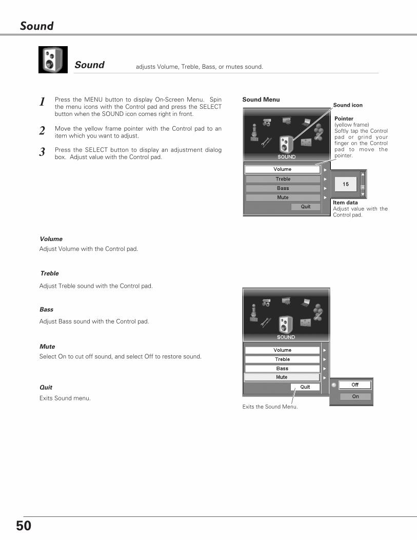
50
Exits Sound menu.
Quit
1
Adjust Volume with the Control pad.
Select On to cut off sound, and select Off to restore sound.
Volume
Mute
Sound Menu
Treble
Adjust Treble sound with the Control pad.
Bass
Adjust Bass sound with the Control pad.
Sound adjusts Volume, Treble, Bass, or mutes sound.
Press the MENU button to display On-Screen Menu. Spinthe menu icons with the Control pad and press the SELECTbutton when the SOUND icon comes right in front.
2 Move the yellow frame pointer with the Control pad to anitem which you want to adjust.
Press the SELECT button to display an adjustment dialogbox. Adjust value with the Control pad.3
Pointer (yellow frame)Softly tap the Controlpad or grind yourfinger on the Controlpad to move thepointer.
Item dataAdjust value with theControl pad.
Exits the Sound Menu.
Sound
Sound icon
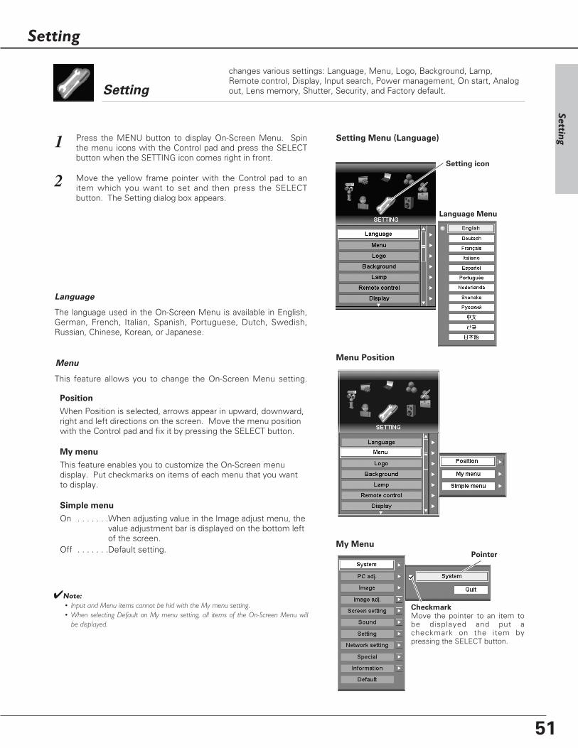
51
Menu
1
2
Setting
Setting
Language
The language used in the On-Screen Menu is available in English,German, French, Italian, Spanish, Portuguese, Dutch, Swedish,Russian, Chinese, Korean, or Japanese.
This feature allows you to change the On-Screen Menu setting.
Position
When Position is selected, arrows appear in upward, downward,right and left directions on the screen. Move the menu positionwith the Control pad and fix it by pressing the SELECT button.
My menu
This feature enables you to customize the On-Screen menudisplay. Put checkmarks on items of each menu that you wantto display.
Simple menu
On . . . . . . .When adjusting value in the Image adjust menu, thevalue adjustment bar is displayed on the bottom leftof the screen.
Off . . . . . . .Default setting.
Setting Menu (Language)
changes various settings: Language, Menu, Logo, Background, Lamp,Remote control, Display, Input search, Power management, On start, Analogout, Lens memory, Shutter, Security, and Factory default.
Press the MENU button to display On-Screen Menu. Spinthe menu icons with the Control pad and press the SELECTbutton when the SETTING icon comes right in front.
Move the yellow frame pointer with the Control pad to anitem which you want to set and then press the SELECTbutton. The Setting dialog box appears.
Menu Position
Setting
Setting icon
Language Menu
✔Note:• Input and Menu items cannot be hid with the My menu setting.• When selecting Default on My menu setting, all items of the On-Screen Menu will
be displayed.
My Menu
CheckmarkMove the pointer to an item tobe displayed and put acheckmark on the item bypressing the SELECT button.
Pointer
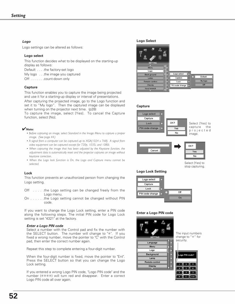
52
Setting
Logo
Logo settings can be altered as follows:
Logo select
This function decides what to be displayed on the starting-updisplay as follows:Default . . . .the factory-set logoMy logo . . .the image you captured Off . . . . . . .count-down only
Capture
This function enables you to capture the image being projectedand use it for a starting-up display or interval of presentations. After capturing the projected image, go to the Logo function andset it to “My logo”. Then the captured image can be displayedwhen turning on the projector next time. (p28) To capture the image, select [Yes]. To cancel the Capturefunction, select [No].
✔Note:• Before capturing an image, select Standard in the Image Menu to capture a proper
image. (See page 44.)• A signal from a computer can be captured up to XGA(1024 x 768). A signal from
video equipment can be captured except for 720p, 1035i, and 1080i.• When capturing the image that has been adjusted by the Keystone function, the
adjustment data is automatically reset and the projector captures an image withoutkeystone correction.
• When the Logo lock function is On, the Logo and Capture menu cannot beselected.
Logo Lock SettingLock
This function prevents an unauthorized person from changing theLogo setting.
Off . . . . .the Logo setting can be changed freely from theLogo menu.
On . . . . . .the Logo setting cannot be changed without PINcode.
If you want to change the Logo Lock setting, enter a PIN codealong the following steps. The initial PIN code for Logo Locksetting is set "4321" at the factory.
Select [Yes] tocapture thep r o j e c t e dimage.
Select [Yes] tostop capturing.
Capture
Logo Select
Enter a Logo PIN code Select a number with the Control pad and fix the number withthe SELECT button. The number will change to "✳". If youfixed a wrong number, move the pointer to "C" with the Controlpad, then enter the correct number again.
Repeat this step to complete entering a four-digit number.
When the four-digit number is fixed, move the pointer to "Ent".Press the SELECT button so that you can change the LogoLock setting.
If you entered a wrong Logo PIN code, "Logo PIN code" and thenumber (✳✳✳✳) will turn red and disappear. Enter a correctLogo PIN code all over again.
Enter a Logo PIN code
The input numberschange to “✳” forsecurity.
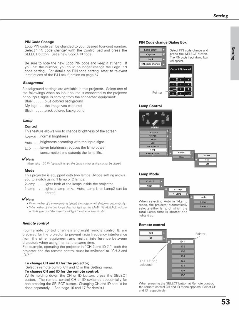
53
Setting
PIN Code Change
Logo PIN code can be changed to your desired four-digit number.Select "PIN code change" with the Control pad and press theSELECT button. Set a new Logo PIN code.
Be sure to note the new Logo PIN code and keep it at hand. Ifyou lost the number, you could no longer change the Logo PINcode setting. For details on PIN code setting, refer to relevantinstructions of the PJ Lock function on page 57.
Background
3 background settings are available in this projector. Select one ofthe followings when no input source is connected to the projectoror no input signal is coming from the connected equipment:
Blue . . . . . .blue colored backgroundMy logo . . .the image you captured Black . . . . .black colored background
Lamp
Control
This feature allows you to change brightness of the screen.
Normal . .normal brightness
Auto . . . .brightness according with the input signal
Eco . . . .lower brightness reduces the lamp power consumption and extends the lamp life.
Mode
This projector is equipped with two lamps. Mode setting allowsyou to switch using 1 lamp or 2 lamps. 2-lamp . . . .lights both of the lamps inside the projector.1-lamp . . .lights a lamp only. Auto, Lamp1, or Lamp2 can be
altered.
PIN Code change Dialog Box
Pointer
Select PIN code change andpress the SELECT button.The PIN code input dialog boxwill appear.
Lamp Control
✔Note:• When neither of the two lamps is lighted, the projector will shutdown automatically. • When either of the two lamps does not light up, the LAMP 1/2 REPLACE indicator
is blinking red and the projector will light the other automatically.
Setting
Lamp Mode
When selecting Auto in 1-Lampmode, the projector automaticallyselects either lamp of which thetotal Lamp time is shorter andlights it up.
✔Note:When using 100 W (optional) lamps, the Lamp control setting cannot be altered.
Remote control
Four remote control channels and eight remote control ID areprepared for the projector to prevent radio frequency interferencefrom the other equipment and mutual interference betweenprojectors when using them at the same time.For example, operating the projector in “CH-2 and ID-7,” both theprojector and the remote control must be switched to “CH-2 andID-7.”
To change CH and ID for the projector;
Select a remote control CH and ID in this Setting menu.To change CH and ID for the remote control;
While holding down the CH or ID button, press the SELECTbutton. The remote control CH or ID switches sequentially forone pressing the SELECT button. Changing CH and ID should bedone separately. (See page 16 and 17 for details.)
Remote control
When pressing the SELECT button at Remote control,the remote control CH and ID menu appears. Select CHand ID respectively.
The settingselected.
Pointer
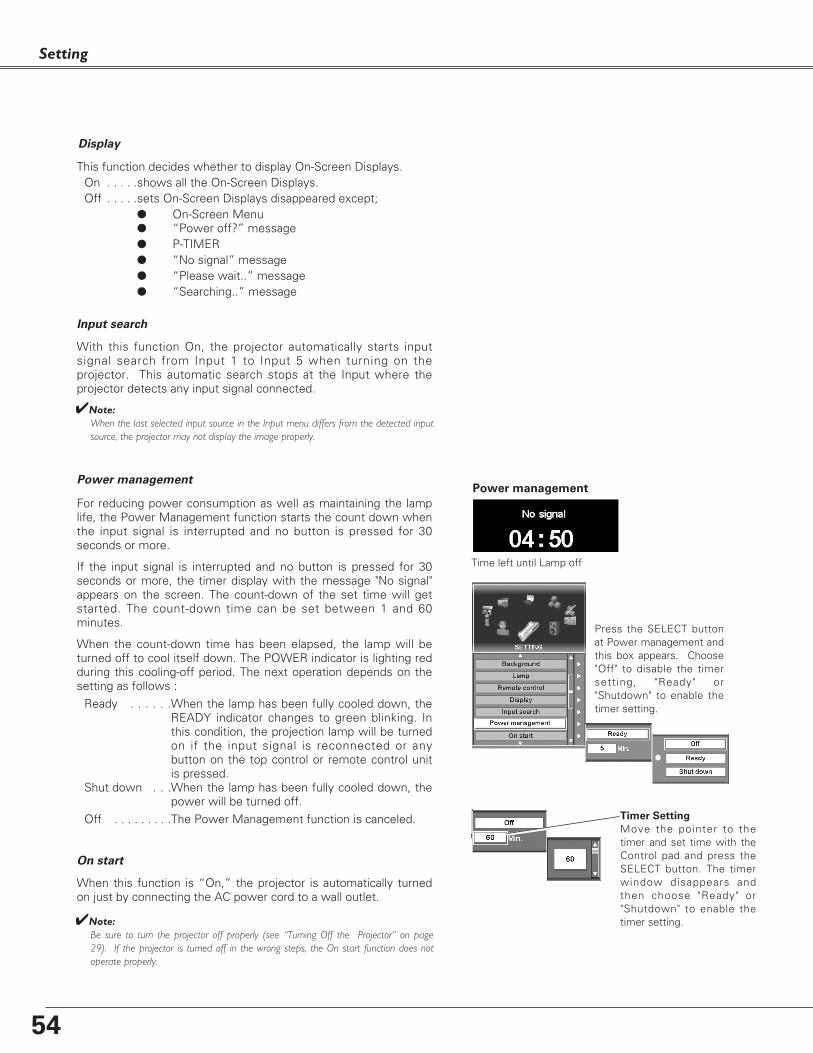
54
On start
When this function is “On,” the projector is automatically turnedon just by connecting the AC power cord to a wall outlet.
✔Note:Be sure to turn the projector off properly (see “Turning Off the Projector” on page29). If the projector is turned off in the wrong steps, the On start function does notoperate properly.
Setting
Display
This function decides whether to display On-Screen Displays.On . . . . .shows all the On-Screen Displays.Off . . . . .sets On-Screen Displays disappeared except;
● On-Screen Menu ● “Power off?” message● P-TIMER● “No signal” message ● “Please wait..” message ● “Searching..” message
Input search
With this function On, the projector automatically starts inputsignal search from Input 1 to Input 5 when turning on theprojector. This automatic search stops at the Input where theprojector detects any input signal connected.
Power management
Time left until Lamp off
Press the SELECT buttonat Power management andthis box appears. Choose"Off" to disable the timersetting, "Ready" or"Shutdown" to enable thetimer setting.
Power management
For reducing power consumption as well as maintaining the lamplife, the Power Management function starts the count down whenthe input signal is interrupted and no button is pressed for 30seconds or more.
If the input signal is interrupted and no button is pressed for 30seconds or more, the timer display with the message "No signal"appears on the screen. The count-down of the set time will getstarted. The count-down time can be set between 1 and 60minutes.
When the count-down time has been elapsed, the lamp will beturned off to cool itself down. The POWER indicator is lighting redduring this cooling-off period. The next operation depends on thesetting as follows :
Ready . . . . . .When the lamp has been fully cooled down, theREADY indicator changes to green blinking. Inthis condition, the projection lamp will be turnedon if the input signal is reconnected or anybutton on the top control or remote control unitis pressed.
Shut down . . .When the lamp has been fully cooled down, thepower will be turned off.
Off . . . . . . . . .The Power Management function is canceled. Timer Setting
Move the pointer to thetimer and set time with theControl pad and press theSELECT button. The timerwindow disappears andthen choose "Ready" or"Shutdown" to enable thetimer setting.
✔Note:When the last selected input source in the Input menu differs from the detected inputsource, the projector may not display the image properly.
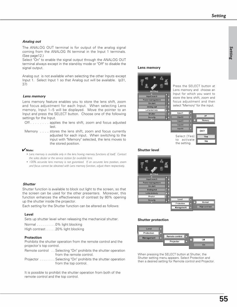
55
Setting
Analog out
The ANALOG OUT terminal is for output of the analog signalcoming from the ANALOG IN terminal in the Input 1 terminals.(See page12.)Select "On" to enable the signal output through the ANALOG OUTterminal always except in the stand-by mode or "Off" to disable thesignal output.
Analog out is not available when selecting the other Inputs exceptInput 1. Select Input 1 so that Analog out will be available. (p31,37)
Lens memory
Lens memory feature enables you to store the lens shift, zoomand focus adjustment for each Input. When selecting Lensmemory, Input 1~5 will be displayed. Move the pointer to anInput and press the SELECT button. Choose one of the followingsettings for the Input.
Off . . . . . . . . applies the lens shift, zoom and focus adjustedlast.
Memory . . . . stores the lens shift, zoom and focus currentlyadjusted for each input. When switching to theinput with "Memory" selected, the lens moves tothe stored position.
Lens memory
Shutter function is available to block out light to the screen, so thatthe screen can be used for the other presenters. Moreover, thisfunction enhances the effectiveness of contrast by 80% openingup the shutter inside the projector.Each setting for the Shutter function can be altered as follows:
Level
Sets up shutter level when releasing the mechanical shutter.
Normal . . . . . . . . . .0% light blocking High contrast . . . . .20% light blocking
Protection
Prohibits the shutter operation from the remote control and theprojector's top control.Remote control . . Selecting "On" prohibits the shutter operation
from the remote control.Projector . . . . . . . . Selecting "On" prohibits the shutter operation
from the top control.
It is possible to prohibit the shutter operation from both of theremote control and the top control.
Shutter
Shutter level
Shutter protection
Setting
Select [Yes]to activatethe setting.
Press the SELECT button atLens memory and choose anInput for which you want tostore the lens shift, zoom andfocus adjustment and thenselect "Memory" for the input.
When pressing the SELECT button at Shutter, theShutter setting menu appears. Select Protection andthen a desired setting for Remote control and Projector.
✔Note:• Lens memory is available only in the lens having memory functions of itself. Contact
the sales dealer or the service station for available lens.• 100% accurate lens memory is not guranteed. If an accurate lens position, zoom
and focus cannot be obtained with Lens memory function, adjust them respectively.
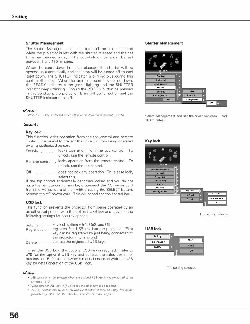
56
Setting
Security
Key lock
This function locks operation from the top control and remotecontrol. It is useful to prevent the projector from being operatedby an unauthorized person. Projector . . . . . . .locks operation from the top control. To
unlock, use the remote control.
Remote control . .locks operation from the remote control. Tounlock, use the top control.
Off . . . . . . . . . . . .does not lock any operation. To release lock,select this.
If the top control accidentally becomes locked and you do nothave the remote control nearby, disconnect the AC power cordfrom the AC outlet, and then with pressing the SELECT button,reinsert the AC power cord. This will cancel the top control lock.
Key lock
Shutter Management
The Shutter Management function turns off the projection lampwhen the projector is left with the shutter released and the settime has passed away. The count-down time can be setbetween 5 and 180 minutes.
When the count-down time has elapsed, the shutter will beopened up automatically and the lamp will be turned off to coolitself down. The SHUTTER indicator is blinking blue during thiscooling-off period. When the lamp has been fully cooled down,the READY indicator turns green lighting and the SHUTTERindicator keeps blinking. Should the POWER button be pressedin this condition, the projection lamp will be turned on and theSHUTTER indicator turns off.
Shutter Management
USB lock
This function prevents the projector from being operated by anunauthorized person with the optional USB key and provides thefollowing settings for security options.
Setting . . . . . .key lock setting (On1, On2, and Off)Registration . .registers 2nd USB key into the projector. (First
key can be registered by just being connected tothe projector in turning on.)
Delete . . . . . . .deletes the registered USB keys.
To set the USB lock, the optional USB key is required. Refer top75 for the optional USB key and contact the sales dealer forpurchasing. Refer to the owner's manual enclosed with the USBkey for detail operation of the USB lock.
USB lock
✔Note:• USB lock cannot be selected when the optional USB key is not connected to the
projector. (p13)• When either of USB lock or PJ lock is set, the other cannot be selected.• USB key function can be used only with our specified optional USB key. We do not
guarantee operation with the other USB keys commarcially supplied.
Select Management and set the timer between 5 and180 minutes.
The setting selected.
The setting selected.
✔Note:While the Shutter is released, timer setting of the Power management is invalid.
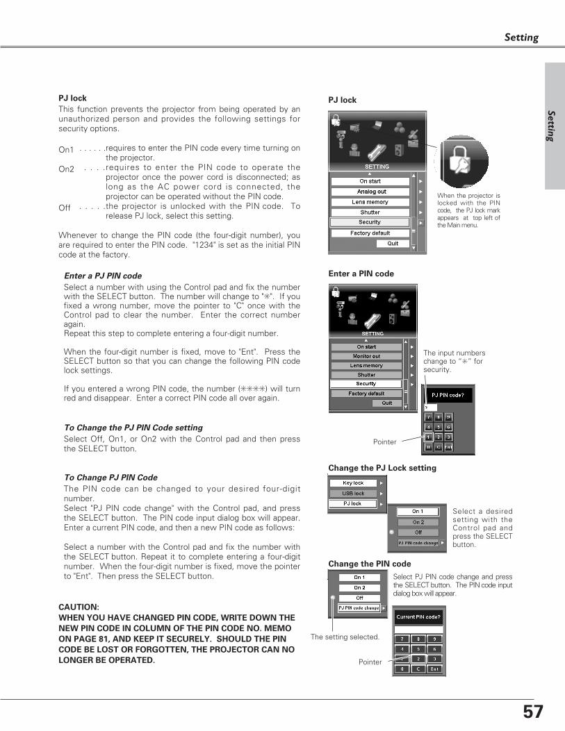
57
Setting
The PIN code can be changed to your desired four-digitnumber.Select "PJ PIN code change" with the Control pad, and pressthe SELECT button. The PIN code input dialog box will appear.Enter a current PIN code, and then a new PIN code as follows:
Select a number with the Control pad and fix the number withthe SELECT button. Repeat it to complete entering a four-digitnumber. When the four-digit number is fixed, move the pointerto "Ent". Then press the SELECT button.
To Change PJ PIN Code
Select Off, On1, or On2 with the Control pad and then pressthe SELECT button.
To Change the PJ PIN Code setting
CAUTION:
WHEN YOU HAVE CHANGED PIN CODE, WRITE DOWN THE
NEW PIN CODE IN COLUMN OF THE PIN CODE NO. MEMO
ON PAGE 81, AND KEEP IT SECURELY. SHOULD THE PIN
CODE BE LOST OR FORGOTTEN, THE PROJECTOR CAN NO
LONGER BE OPERATED.
Enter a PIN codeEnter a PJ PIN code
Select a number with using the Control pad and fix the numberwith the SELECT button. The number will change to "✳". If youfixed a wrong number, move the pointer to "C" once with theControl pad to clear the number. Enter the correct numberagain.Repeat this step to complete entering a four-digit number.
When the four-digit number is fixed, move to "Ent". Press theSELECT button so that you can change the following PIN codelock settings.
If you entered a wrong PIN code, the number (✳✳✳✳) will turnred and disappear. Enter a correct PIN code all over again.
Change the PIN code
Select PJ PIN code change and pressthe SELECT button. The PIN code inputdialog box will appear.
Select a desiredsetting with theControl pad andpress the SELECTbutton.
Change the PJ Lock setting
The input numberschange to “✳” forsecurity.
PJ lock
This function prevents the projector from being operated by anunauthorized person and provides the following settings forsecurity options.
On1 . . . . . .requires to enter the PIN code every time turning onthe projector.
On2 . . . .requires to enter the PIN code to operate theprojector once the power cord is disconnected; aslong as the AC power cord is connected, theprojector can be operated without the PIN code.
Off . . . . .the projector is unlocked with the PIN code. Torelease PJ lock, select this setting.
Whenever to change the PIN code (the four-digit number), youare required to enter the PIN code. "1234" is set as the initial PINcode at the factory.
PJ lock
When the projector islocked with the PINcode, the PJ lock markappears at top left ofthe Main menu.
Setting
Pointer
Pointer
The setting selected.
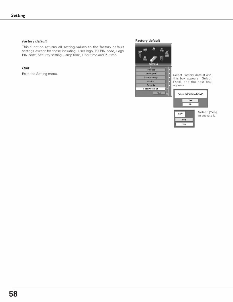
58
Setting
Factory default
This function returns all setting values to the factory defaultsettings except for those including: User logo, PJ PIN code, LogoPIN code, Security setting, Lamp time, Filter time and PJ time.
Select Factory default andthis box appears. Select[Yes], and the next boxappears.
Factory default
Quit
Exits the Setting menu.
Select [Yes]to activate it.
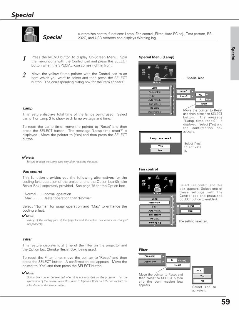
59
Special customizes control functions: Lamp, Fan control, Filter, Auto PC adj., Test pattern, RS-232C, and USB memory and displays Warning log.
✔Note:Be sure to reset the Lamp time only after replacing the lamp.
1
2
Press the MENU button to display On-Screen Menu. Spinthe menu icons with the Control pad and press the SELECTbutton when the SPECIAL icon comes right in front.
Move the yellow frame pointer with the Control pad to anitem which you want to select and then press the SELECTbutton. The corresponding dialog box for the item appears.
Lamp
This feature displays total time of the lamps being used. SelectLamp 1 or Lamp 2 to show each lamp wattage and time.
To reset the Lamp time, move the pointer to "Reset" and thenpress the SELECT button. The message "Lamp time reset?" isdisplayed. Move the pointer to [Yes] and then press the SELECTbutton.
Move the pointer to Resetand then press the SELECTbutton. The message“Lamp time reset?” isdisplayed. Select [Yes] andthe confirmation boxappears.
Special Menu (Lamp)
Fan controlFan control
This function provides you the following alternatives for thecooling fans operation of the projector and the Option box (SmokeResist Box ) separately provided. See page 75 for the Option box.
Normal . . .normal operation Max . . . . . .faster operation than "Normal".
Select "Normal" for usual operation and "Max" to enhance thecooling effect.
Filter
This feature displays total time of the filter on the projector andthe Option box (Smoke Resist Box) being used.
To reset the Filter time, move the pointer to "Reset" and thenpress the SELECT button. A confirmation box appears. Move thepointer to [Yes] and then press the SELECT button.
Filter
SpecialSp
ecial
Special icon
Select [Yes]to activateit.
✔Note:Setting of the cooling fans of the projector and the option box cannot be changedindependently.
✔Note:Option box cannot be selected when it is not mounted on the projector. For theinformation of the Smoke Resist Box, refer to Optional Parts on p75 and contact thesales dealer or the service station.
Select Fan control and thisbox appears. Select one ofthese settings with theControl pad and press theSELECT button to enable it.
The setting selected.
Move the pointer to Reset andthen press the SELECT buttonand the confirmation boxappears. Select [Yes] to
activate it.
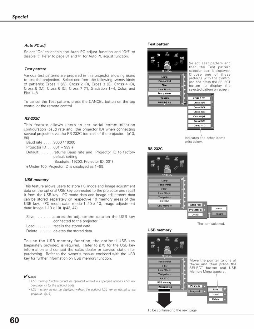
60
Special
Auto PC adj.
Select "On" to enable the Auto PC adjust function and "Off" todisable it. Refer to page 31 and 41 for Auto PC adjust function.
Test pattern
Various test patterns are prepared in this projector allowing usersto test the projection. Select one from the following twenty kindsof patterns: Cross 1 (W), Cross 2 (R), Cross 3 (G), Cross 4 (B),Cross 5 (M), Cross 6 (C), Cross 7 (Y), Gradation 1~4, Color, andFlat 1~8.
To cancel the Test pattern, press the CANCEL button on the topcontrol or the remote control.
Select Test pattern andthen the Test patternselection box is displayed.Choose one of thesepatterns with the Controlpad and press the SELECTbutton to display theselected pattern on screen.
Test pattern
Indicates the other itemsexist below.
RS-232C
This feature al lows users to set serial communicationconfiguration (baud rate and the projector ID) when connectingseveral projectors via the RS-232C terminal of the projector. (p13,80)
Baud rate . . . . .9600 / 19200Projector ID . . .001 ~ 999 ✽Default . . . . .returns Baud rate and Projector ID to factory
default setting (Baudrate: 19200, Projector ID: 001)
✽ Under 100, Projector ID is displayed as 1~99.
USB memory
This feature allows users to store PC mode and Image adjustmentdata on the optional USB key connected to the projector and recallit from the USB key. PC mode data and Image adjustment datacan be stored separately on respective 10 memory areas of theUSB key. (PC mode data: mode 1–50 x 10, Image adjustmentdata: Image 1-10 x 10) (p43, 47)
Save . . . . . .stores the adjustment data on the USB keyconnected to the projector.
Load . . . . . . . . .recalls the stored data.Delete . . . . . . .deletes the stored data.
To use the USB memory function, the optional USB key(separately provided) is required. Refer to p75 for the USB keyinformation and contact the sales dealer or service station forpurchasing. Refer to the owner's manual enclosed with the USBkey for further information on USB memory function.
RS-232C
USB memory
✔Note:• USB memory function cannot be operated without our specified optional USB key.
See page 75 for the optional parts.• USB memory cannot be displayed without the optional USB key connected to the
projector. (p13)
The item selected.
Move the pointer to one ofthese and then press theSELECT button and USBMemory Menu appears .
To be continued to the next page.
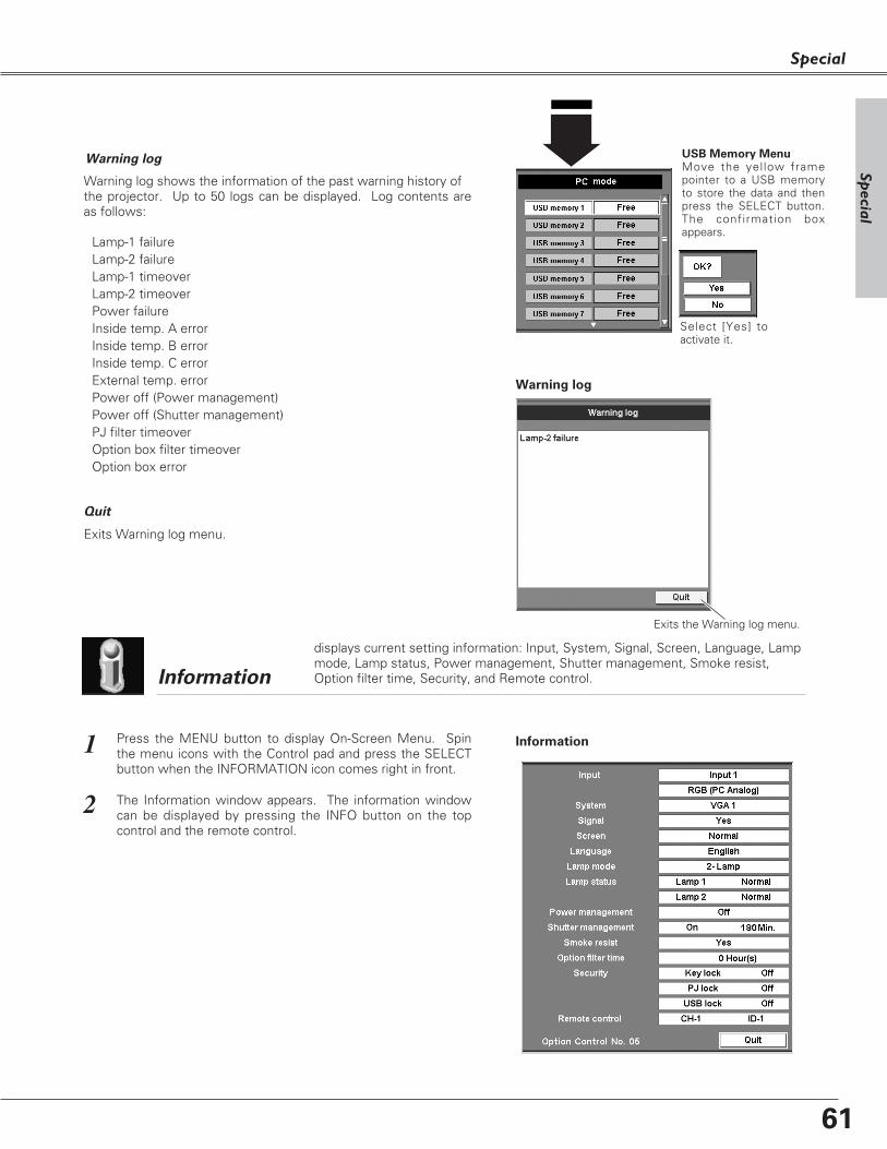
61
Special
Warning log
Warning log shows the information of the past warning history of the projector. Up to 50 logs can be displayed. Log contents areas follows:
Lamp-1 failureLamp-2 failureLamp-1 timeoverLamp-2 timeoverPower failureInside temp. A errorInside temp. B errorInside temp. C errorExternal temp. errorPower off (Power management)Power off (Shutter management)PJ filter timeoverOption box filter timeoverOption box error
Warning log
Exits Warning log menu.
Quit
Information
displays current setting information: Input, System, Signal, Screen, Language, Lampmode, Lamp status, Power management, Shutter management, Smoke resist,Option filter time, Security, and Remote control.
Information1
2
Press the MENU button to display On-Screen Menu. Spinthe menu icons with the Control pad and press the SELECTbutton when the INFORMATION icon comes right in front.
The Information window appears. The information windowcan be displayed by pressing the INFO button on the topcontrol and the remote control.
Special
Select [Yes] toactivate it.
USB Memory MenuMove the yellow framepointer to a USB memoryto store the data and thenpress the SELECT button.The confirmation boxappears.
Exits the Warning log menu.
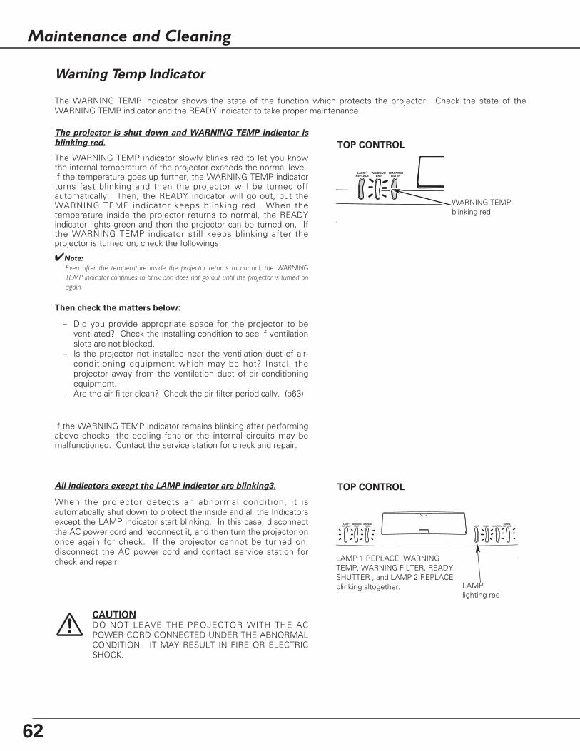
62
If the WARNING TEMP indicator remains blinking after performingabove checks, the cooling fans or the internal circuits may bemalfunctioned. Contact the service station for check and repair.
Warning Temp Indicator
The WARNING TEMP indicator shows the state of the function which protects the projector. Check the state of theWARNING TEMP indicator and the READY indicator to take proper maintenance.
TOP CONTROL
The projector is shut down and WARNING TEMP indicator is
blinking red.
The WARNING TEMP indicator slowly blinks red to let you knowthe internal temperature of the projector exceeds the normal level.If the temperature goes up further, the WARNING TEMP indicatorturns fast blinking and then the projector will be turned offautomatically. Then, the READY indicator will go out, but theWARNING TEMP indicator keeps blinking red. When thetemperature inside the projector returns to normal, the READYindicator lights green and then the projector can be turned on. Ifthe WARNING TEMP indicator still keeps blinking after theprojector is turned on, check the followings;
✔Note:Even after the temperature inside the projector returns to normal, the WARNINGTEMP indicator continues to blink and does not go out until the projector is turned onagain.
Then check the matters below:
– Did you provide appropriate space for the projector to beventilated? Check the installing condition to see if ventilationslots are not blocked.
– Is the projector not installed near the ventilation duct of air-conditioning equipment which may be hot? Install theprojector away from the ventilation duct of air-conditioningequipment.
– Are the air filter clean? Check the air filter periodically. (p63)
LAMP 1 REPLACE, WARNINGTEMP, WARNING FILTER, READY,SHUTTER , and LAMP 2 REPLACEblinking altogether.
TOP CONTROLAll indicators except the LAMP indicator are blinking3.
When the projector detects an abnormal condition, it isautomatically shut down to protect the inside and all the Indicatorsexcept the LAMP indicator start blinking. In this case, disconnectthe AC power cord and reconnect it, and then turn the projector ononce again for check. If the projector cannot be turned on,disconnect the AC power cord and contact service station forcheck and repair.
CAUTIONDO NOT LEAVE THE PROJECTOR WITH THE ACPOWER CORD CONNECTED UNDER THE ABNORMALCONDITION. IT MAY RESULT IN FIRE OR ELECTRICSHOCK.
WARNING TEMPblinking red
LAMP lighting red
Maintenance and Cleaning
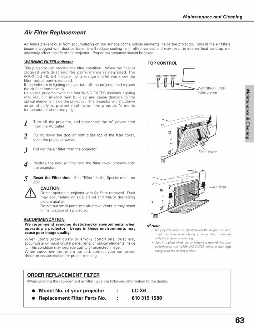
63
Maintenance and Cleaning
Turn off the projector, and disconnect the AC power cordfrom the AC outlet.1
2
3
4
RECOMMENDATIONWe recommend avoiding dusty/smoky environments whenoperating a projector. Usage in these environments maycause poor image quality.
When using under dusty or smoky conditions, dust mayaccumulate on liquid crystal panel, lens, or optical elements insideit. This condition may degrade quality of projected image.When above symptoms are noticed, contact your authorizeddealer or service station for proper cleaning.
Pulling down the tabs on both sides top of the filter cover,open the projector cover.
Pull out the air filter from the projector.
Replace the new air filter and the filter cover properly ontothe projector.
Reset the Filter time. See “Filter” in the Special menu onp59.
5
Filter cover
CAUTIONDo not operate a projector with Air Filter removed. Dustmay accumulate on LCD Panel and Mirror degradingpicture quality.Do not put small parts into Air Intake Vents. It may resultin malfunction of a projector.
Air Filter Replacement
Air filter
Air filters prevent dust from accumulating on the surface of the optical elements inside the projector. Should the air filtersbecome clogged with dust particles, it will reduce cooling fans’ effectiveness and may result in internal heat build up andadversely affect the life of the projector. Proper maintenance should be taken.
TOP CONTROL
WARNING FILTERlights orange
This projector can monitor the filter condition. When the filter isclogged with dust and the performance is degraded, theWARNING FILTER indicator lights orange and let you know thefilter replacement is required. If the indicator is lighting orange, turn off the projector and replacethe air filter immediately.Using the projector with the WARNING FILTER indicator lightingmay result in internal heat build up and cause damage to theoptical elements inside the projector. The projector will shutdownautomatically to protect itself when the projector's insidetemperature is abnormally high.
WARNING FILTER Indicator
Maintenance &
Cleaning
✔Note:• The projector cannot be operated with the air filter removed;
it will shut down automatically if the air filter is removedwhile the projector is operating.
• Used in a place where the air pressure is relatively low suchas highlands, the WARNING FILTER indicator may lightorange even the air filter is clean.
ORDER REPLACEMENT FILTER
When ordering the replacement air filter, give the following information to the dealer.
● Model No. of your projector : LC-X6
● Replacement Filter Parts No. : 610 315 1588
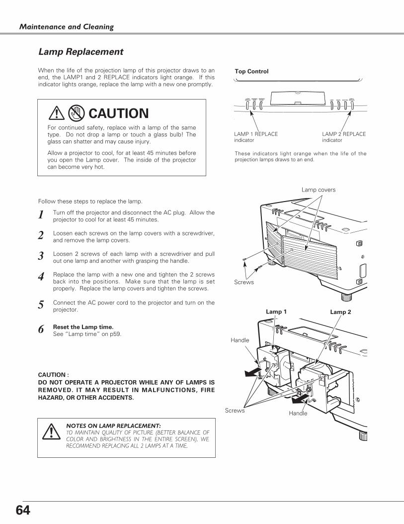
64
Maintenance and Cleaning
CAUTION :
DO NOT OPERATE A PROJECTOR WHILE ANY OF LAMPS IS
REMOVED. IT MAY RESULT IN MALFUNCTIONS, FIRE
HAZARD, OR OTHER ACCIDENTS.
Lamp Replacement
When the life of the projection lamp of this projector draws to anend, the LAMP1 and 2 REPLACE indicators light orange. If thisindicator lights orange, replace the lamp with a new one promptly.
Follow these steps to replace the lamp.
Handle
Lamp covers
For continued safety, replace with a lamp of the sametype. Do not drop a lamp or touch a glass bulb! Theglass can shatter and may cause injury.
Allow a projector to cool, for at least 45 minutes beforeyou open the Lamp cover. The inside of the projectorcan become very hot.
Top Control
CAUTION
Screws
Turn off the projector and disconnect the AC plug. Allow theprojector to cool for at least 45 minutes.
Loosen 2 screws of each lamp with a screwdriver and pullout one lamp and another with grasping the handle.
1
3Replace the lamp with a new one and tighten the 2 screwsback into the positions. Make sure that the lamp is setproperly. Replace the lamp covers and tighten the screws.
4
Loosen each screws on the lamp covers with a screwdriver,and remove the lamp covers.2
Connect the AC power cord to the projector and turn on theprojector.
6 Reset the Lamp time.
See “Lamp time” on p59.
5
HandleScrews
NOTES ON LAMP REPLACEMENT:TO MAINTAIN QUALITY OF PICTURE (BETTER BALANCE OFCOLOR AND BRIGHTNESS IN THE ENTIRE SCREEN), WERECOMMEND REPLACING ALL 2 LAMPS AT A TIME.
These indicators light orange when the life of theprojection lamps draws to an end.
Lamp 1
LAMP 2 REPLACEindicator
LAMP 1 REPLACEindicator
Lamp 2
65
Maintenance and Cleaning
This projector uses a high-pressure lamp which must be handled carefully and properly. Improper handling may resultin accidents, injury, or create a fire hazard.
● Lamp lifetime may differ from lamp to lamp and according to the environment of use. There is no guarantee of thesame lifetime for each lamp. Some lamps may fail or terminate their lifetime in a shorter period of time than othersimilar lamps.
● If the projector indicates that the lamp should be replaced, i.e., if the LAMP REPLACE INDICATOR lights up,replace the lamp with a new one IMMEDIATELY after the projector has cooled down. ( Follow carefully the instructions in the LAMP REPLACEMENT section of this manual.) Continuous use of thelamp with the LAMP REPLACE INDICATOR lighted may increase the risk of lamp explosion.
● A Lamp may explode as a result of vibration, shock or degradation as a result of hours of use as its lifetime drawsto an end. Risk of explosion may differ according to the environment or conditions in which the projector and lampare being used.
IF A LAMP EXPLODES, THE FOLLOWING SAFETY PRECAUTIONS SHOULD BE TAKEN.
If a lamp explodes, disconnect the projector’s AC plug from the AC outlet immediately. Contact an authorized servicestation for a checkup of the unit and replacement of the lamp. Additionally, check carefully to ensure that there areno broken shards or pieces of glass around the projector or coming out from the cooling air circulation holes. Anybroken shards found should be cleaned up carefully. No one should check the inside of the projector except thosewho are authorized trained technicians and who are familiar with projector service. Inappropriate attempts to servicethe unit by anyone, especially those who are not appropriately trained to do so, may result in an accident or injurycaused by pieces of broken glass.
ORDER REPLACEMENT LAMP
Replacement Lamp can be ordered through your dealer. When ordering a Projection Lamp, give the followinginformation to the dealer.
● Model No. of your projector : LC-X6
● Replacement Lamp Type No. : POA-LMP80(Service Parts No. 610 315 7689)
LAMP HANDLING PRECAUTIONS
Maintenance &
Cleaning
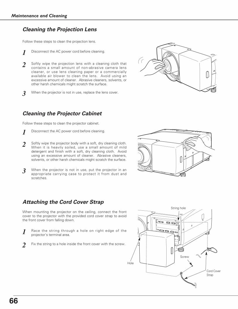
66
Maintenance and Cleaning
Disconnect the AC power cord before cleaning.
When the projector is not in use, replace the lens cover.
1
3
2
Follow these steps to clean the projection lens.
Disconnect the AC power cord before cleaning.1Softly wipe the projector body with a soft, dry cleaning cloth.When it is heavily soiled, use a small amount of milddetergent and finish with a soft, dry cleaning cloth. Avoidusing an excessive amount of cleaner. Abrasive cleaners,solvents, or other harsh chemicals might scratch the surface.
2
Follow these steps to clean the projector cabinet.
When the projector is not in use, put the projector in anappropriate carrying case to protect it from dust andscratches.
3
Softly wipe the projection lens with a cleaning cloth thatcontains a small amount of non-abrasive camera lenscleaner, or use lens cleaning paper or a commerciallyavailable air blower to clean the lens. Avoid using anexcessive amount of cleaner. Abrasive cleaners, solvents, orother harsh chemicals might scratch the surface.
When mounting the projector on the ceiling, connect the frontcover to the projector with the provided cord cover strap to avoidthe front cover from falling down.
Race the string through a hole on right edge of theprojector's terminal area.1
2 Fix the string to a hole inside the front cover with the screw.
Screw
Cord CoverStrap
Hole
Attaching the Cord Cover StrapString hole
Cleaning the Projector Cabinet
Cleaning the Projection Lens
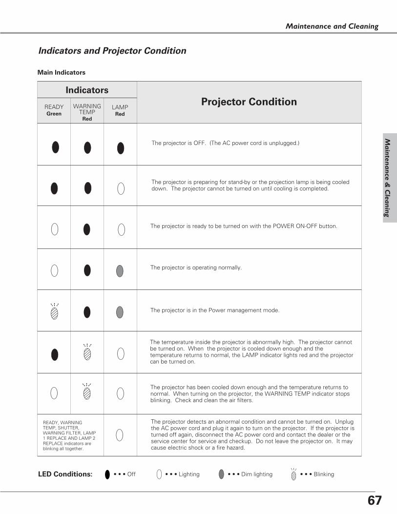
67
Maintenance and Cleaning
Maintenance &
Cleaning
READYGreen
LAMP Red
WARNINGTEMP
Red
Indicators
The projector is OFF. (The AC power cord is unplugged.)
The projector is preparing for stand-by or the projection lamp is being cooleddown. The projector cannot be turned on until cooling is completed.
The projector is operating normally.
The projector is in the Power management mode.
The temperature inside the projector is abnormally high. The projector cannotbe turned on. When the projector is cooled down enough and thetemperature returns to normal, the LAMP indicator lights red and the projectorcan be turned on.
The projector detects an abnormal condition and cannot be turned on. Unplugthe AC power cord and plug it again to turn on the projector. If the projector isturned off again, disconnect the AC power cord and contact the dealer or theservice center for service and checkup. Do not leave the projector on. It maycause electric shock or a fire hazard.
The projector is ready to be turned on with the POWER ON-OFF button.
The projector has been cooled down enough and the temperature returns tonormal. When turning on the projector, the WARNING TEMP indicator stopsblinking. Check and clean the air filters.
Projector Condition
• • • Off • • • Dim lighting• • • Lighting • • • BlinkingLED Conditions:
Main Indicators
Indicators and Projector Condition
READY, WARNINGTEMP, SHUTTER,WARNING FILTER, LAMP1 REPLACE AND LAMP 2REPLACE indicators areblinking all together.
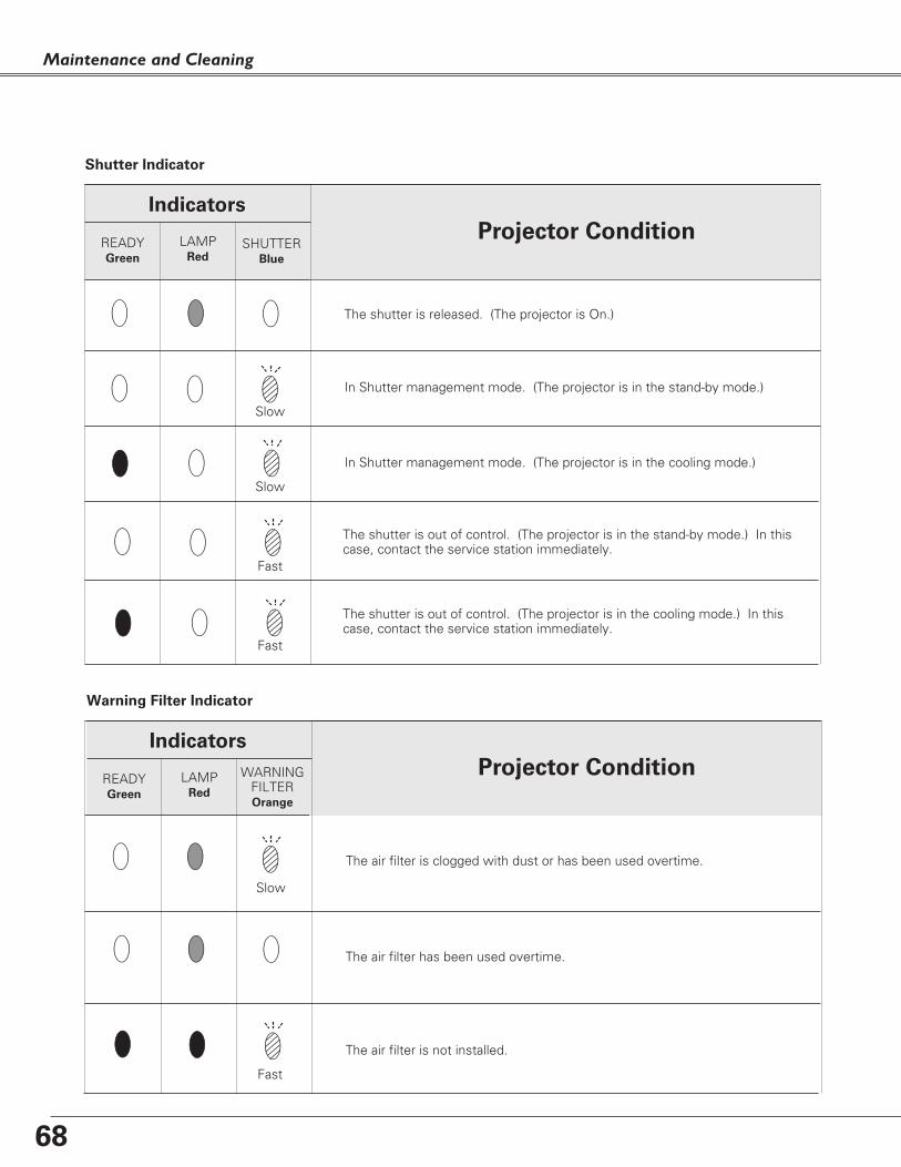
68
Maintenance and Cleaning
READYGreen
SHUTTERBlue
LAMPRed
Indicators
The shutter is released. (The projector is On.)
The shutter is out of control. (The projector is in the stand-by mode.) In thiscase, contact the service station immediately.
Projector Condition
Slow
Fast
READYGreen
WARNINGFILTEROrange
LAMPRed
Indicators
The air filter is clogged with dust or has been used overtime.
The air filter has been used overtime.
Projector Condition
Fast
Warning Filter Indicator
In Shutter management mode. (The projector is in the stand-by mode.)
Slow
The air filter is not installed.
Slow
Fast
The shutter is out of control. (The projector is in the cooling mode.) In thiscase, contact the service station immediately.
In Shutter management mode. (The projector is in the cooling mode.)
Shutter Indicator
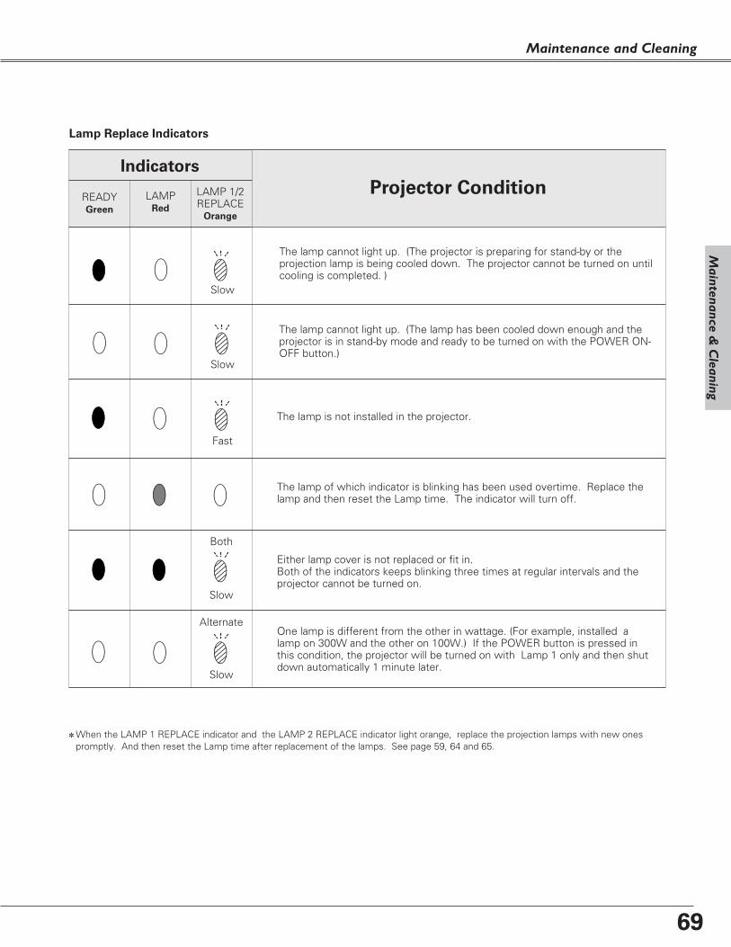
69
Maintenance and Cleaning
✽ When the LAMP 1 REPLACE indicator and the LAMP 2 REPLACE indicator light orange, replace the projection lamps with new onespromptly. And then reset the Lamp time after replacement of the lamps. See page 59, 64 and 65.
Maintenance &
Cleaning
Lamp Replace Indicators
READYGreen
LAMP 1/2REPLACE
Orange
LAMPRed
Indicators
The lamp cannot light up. (The projector is preparing for stand-by or theprojection lamp is being cooled down. The projector cannot be turned on untilcooling is completed. )
The lamp cannot light up. (The lamp has been cooled down enough and theprojector is in stand-by mode and ready to be turned on with the POWER ON-OFF button.)
The lamp of which indicator is blinking has been used overtime. Replace thelamp and then reset the Lamp time. The indicator will turn off.
Either lamp cover is not replaced or fit in. Both of the indicators keeps blinking three times at regular intervals and theprojector cannot be turned on.
The lamp is not installed in the projector.
Projector Condition
Slow
Slow
Fast
Slow
One lamp is different from the other in wattage. (For example, installed alamp on 300W and the other on 100W.) If the POWER button is pressed inthis condition, the projector will be turned on with Lamp 1 only and then shutdown automatically 1 minute later.
Both
Slow
Alternate
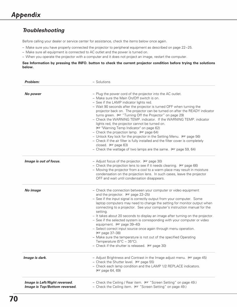
70
Troubleshooting
Before calling your dealer or service center for assistance, check the items below once again.
– Make sure you have properly connected the projector to peripheral equipment as described on page 22~25. – Make sure all equipment is connected to AC outlet and the power is turned on.– When you operate the projector with a computer and it does not project an image, restart the computer.
See Information by pressing the INFO. button to check the current projector condition before trying the solutions
below.
Problem: – Solutions
No power – Plug the power cord of the projector into the AC outlet.– Make sure the Main On/Off switch is on.– See if the LAMP indicator lights red.– Wait 90 seconds after the projector is turned OFF when turning the
projector back on. The projector can be turned on after the READY indicatorturns green. (☞ “Turning Off the Projector” on page 29)
– Check the WARNING TEMP. indicator. If the WARNING TEMP. indicator lights red, the projector cannot be turned on. (☞ "Warning Temp Indicator" on page 62)
– Check the projection lamp. (☞ page 64)– Unlock Key lock for the projector in the Setting Menu. (☞ page 56)– Check if the air filter is fully installed and the filter cover is completely
closed. (☞ page 63)– Check the wattage of two lamps are the same. (☞ page 59, 64)
Image is out of focus. – Adjust focus of the projector. (☞ page 30)– Check the projection lens to see if it needs cleaning. (☞ page 66)– Moving the projector from a cool to a warm place may result in moisture
condensation on the projection lens. In such cases, leave the projector OFF and wait until condensation disappears.
No image – Check the connection between your computer or video equipment and the projector. (☞ page 22–25)
– See if the input signal is correctly output from your computer. Some laptop computers may need to change the setting for monitor output when connecting to a projector. See your computer’s instruction manual for thesetting.
– It takes about 20 seconds to display an image after turning on the projector.– See if the selected system is corresponding with your computer or video
equipment. (☞ page 39–40)– Select correct input source once again through menu operation.
(☞ page 37–38)– Make sure the temperature is not out of the specified Operating
Temperature (5°C ~ 35°C).– Check if the shutter is released. (☞ page 30)
Image is dark. – Adjust Brightness and Contrast in the Image adjust menu. (☞ page 45)– Check the Shutter level. (☞ page 55)– Check each lamp condition and the LAMP 1/2 REPLACE indicators.
(☞ page 64, 69)
Image is Left/Right reversed. – Check the Ceiling / Rear item. (☞ “Screen Setting” on page 49.)Image is Top/Bottom reversed. – Check the Ceiling item. (☞ “Screen Setting” on page 49.)
Appendix
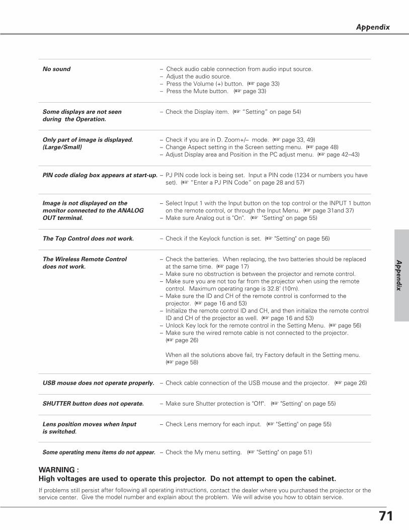
71
Appendix
No sound – Check audio cable connection from audio input source.– Adjust the audio source.– Press the Volume (+) button. (☞ page 33)– Press the Mute button. (☞ page 33)
Some displays are not seen – Check the Display item. (☞ “Setting” on page 54)during the Operation.
Only part of image is displayed. – Check if you are in D. Zoom+/– mode. (☞ page 33, 49)(Large/Small) – Change Aspect setting in the Screen setting menu. (☞ page 48)
– Adjust Display area and Position in the PC adjust menu. (☞ page 42–43)
PIN code dialog box appears at start-up. – PJ PIN code lock is being set. Input a PIN code (1234 or numbers you have set). (☞ “Enter a PJ PIN Code” on page 28 and 57)
Image is not displayed on the – Select Input 1 with the Input button on the top control or the INPUT 1 buttonmonitor connected to the ANALOG on the remote control, or through the Input Menu. (☞ page 31and 37) OUT terminal. – Make sure Analog out is "On". (☞ "Setting" on page 55)
The Top Control does not work. – Check if the Keylock function is set. (☞ "Setting" on page 56)
The Wireless Remote Control – Check the batteries. When replacing, the two batteries should be replaced does not work. at the same time. (☞ page 17)
– Make sure no obstruction is between the projector and remote control.– Make sure you are not too far from the projector when using the remote
control. Maximum operating range is 32.8’ (10m).– Make sure the ID and CH of the remote control is conformed to the
projector. (☞ page 16 and 53)– Initialize the remote control ID and CH, and then initialize the remote control
ID and CH of the projector as well. (☞ page 16 and 53)– Unlock Key lock for the remote control in the Setting Menu. (☞ page 56)– Make sure the wired remote cable is not connected to the projector.
(☞ page 26)
When all the solutions above fail, try Factory default in the Setting menu. (☞ page 58)
USB mouse does not operate properly. – Check cable connection of the USB mouse and the projector. (☞ page 26)
SHUTTER button does not operate. – Make sure Shutter protection is "Off". (☞ "Setting" on page 55)
Lens position moves when Input – Check Lens memory for each input. (☞ "Setting" on page 55)is switched.
Some operating menu items do not appear. – Check the My menu setting. (☞ "Setting" on page 51)
WARNING :
High voltages are used to operate this projector. Do not attempt to open the cabinet.
If problems still persist after following all operating instructions, contact the dealer where you purchased the projector or theservice center. Give the model number and explain about the problem. We will advise you how to obtain service.
Ap
pendix
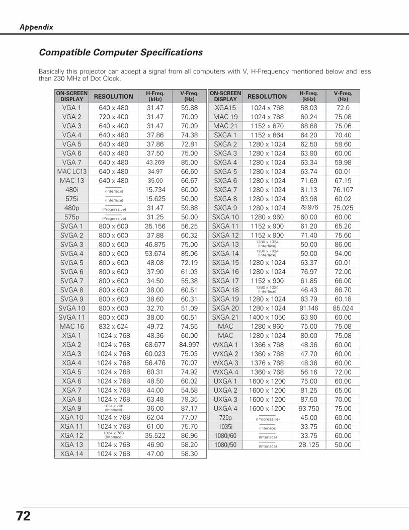
72
Appendix
Basically this projector can accept a signal from all computers with V, H-Frequency mentioned below and lessthan 230 MHz of Dot Clock.
–––––––– (Interlace)
1024 x 768(Interlace)
ON-SCREENDISPLAY
RESOLUTIONH-Freq.(kHz)
V-Freq.(Hz)
VGA 1 640 x 480 31.47 59.88VGA 2 720 x 400 31.47 70.09VGA 3 640 x 400 31.47 70.09VGA 4 640 x 480 37.86 74.38VGA 5 640 x 480 37.86 72.81VGA 6 640 x 480 37.50 75.00
MAC LC13 640 x 480 34.97 66.60MAC 13 640 x 480 35.00 66.67
MAC 16 832 x 624 49.72 74.55
MAC 19 1024 x 768 60.24 75.08MAC 21 1152 x 870 68.68 75.06
UXGA 3 1600 x 1200 87.50 70.00UXGA 4 1600 x 1200 93.750 75.00
SVGA 1 800 x 600 35.156 56.25SVGA 2 800 x 600 37.88 60.32SVGA 3 800 x 600 46.875 75.00SVGA 4 800 x 600 53.674 85.06SVGA 5 800 x 600 48.08 72.19SVGA 6 800 x 600 37.90 61.03SVGA 7 800 x 600 34.50 55.38SVGA 8 800 x 600 38.00 60.51SVGA 9 800 x 600 38.60 60.31
SVGA 11 800 x 600 38.00 60.51
ON-SCREENDISPLAY
RESOLUTIONH-Freq.(kHz)
V-Freq.(Hz)
XGA 11 1024 x 768
XGA 13 1024 x 768XGA 14 1024 x 768
61.00 75.70
XGA15 1024 x 768
46.90 58.20
XGA 8 1024 x 768
47.00 58.30
XGA 9 1024 x 768(Interlace)
58.03 72.0
SXGA 1 1152 x 864SXGA 2 1280 x 1024
63.48 79.35
SXGA 3 1280 x 1024
36.00 87.17
SXGA 4 1280 x 1024
64.20 70.40
SXGA 5 1280 x 1024
62.50 58.60
SXGA 6 1280 x 1024
63.90 60.00
SXGA 7 1280 x 1024
63.34 59.98
SXGA 8 1280 x 1024
63.74 60.01
SXGA 11 1152 x 900
71.69 67.19
SXGA 12 1152 x 900
81.13 76.107
SXGA 13 1280 x 1024(Interlace)
63.98 60.02
SXGA 14 1280 x 1024(Interlace)
61.20 65.2071.40 75.6050.00 86.00
720p –––––––– (Progressive)
50.00 94.00
45.00 60.00
XGA 1 1024 x 768XGA 2 1024 x 768XGA 3 1024 x 768XGA 4 1024 x 768
48.36 60.0068.677 84.997
XGA 6 1024 x 768
60.023 75.03
XGA 7 1024 x 768
56.476 70.07
48.50 60.0244.00 54.58
SXGA 9 1280 x 1024SXGA 10 1280 x 960
79.976 75.02560.00 60.00
SXGA 15 1280 x 1024SXGA 16 1280 x 1024SXGA 17 1152 x 900SXGA 18 1280 x 1024
(Interlace)
63.37 60.0176.97 72.0061.85 66.0046.43 86.70
SXGA 19 1280 x 1024 63.79 60.18
XGA 5 1024 x 768 60.31 74.92
VGA 7 640 x 480 43.269 85.00
575i –––––––– (Interlace) 15.625 50.00
480i –––––––– (Interlace) 15.734 60.00
1080i/60 –––––––– (Interlace) 33.75 60.00
1035i –––––––– (Interlace) 33.75 60.00
SVGA 10 800 x 600 32.70 51.09 SXGA 20 1280 x 1024 91.146 85.024
480p –––––––– (Progressive) 31.47 59.88
XGA 10 1024 x 768 62.04 77.07
1080i/50 28.125 50.00
SXGA 21 1400 x 1050 63.90 60.00MAC 1280 x 960 75.00 75.08
UXGA 1 1600 x 1200 75.00 60.00UXGA 2 1600 x 1200 81.25 65.00
XGA 12 35.522 86.96
575p –––––––– (Progressive) 31.25 50.00
MAC 1280 x 1024 80.00 75.08
WXGA 3 1376 x 768 48.36 60.00WXGA 4 1360 x 768 56.16 72.00
WXGA 1 1366 x 768 48.36 60.00WXGA 2 1360 x 768 47.70 60.00
Compatible Computer Specifications
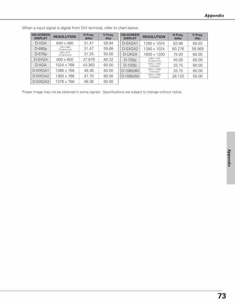
73
Appendix
Proper image may not be obtained in some signals. Specifications are subject to change without notice.
ON-SCREENDISPLAY
RESOLUTIONH-Freq.(kHz)
V-Freq.(Hz)
D-VGA 640 x 480 31.47 59.94D-480p 720 x 480
(Progressive) 31.47 59.88D-575p 768 x 575
(Progressive) 31.25 50.00D-SVGA 800 x 600 37.879 60.32D-XGA 1024 x 768 43.363 60.00
ON-SCREENDISPLAY
RESOLUTIONH-Freq.(kHz)
V-Freq.(Hz)
D-SXGA1 1280 x 1024 63.98 60.02D-SXGA2 1280 x 1024 60.276 58.069
When a input signal is digital from DVI terminal, refer to chart below.
D-WXGA1 1366 x 768 48.36 60.00D-WXGA2 1360 x 768 47.70 60.00D-WXGA3 1376 x 768 48.36 60.00
D-UXGA 1600 x 1200 75.00 60.00
Ap
pendix
D-720p 1280 x 720(Progressive) 45.00 60.00
D-1035i 1920 x 1035(Interlace) 33.75 60.00
D-1080i/60 1920 x 1080(Interlace) 33.75 60.00
D-1080i/50 1920 x 1080(Interlace) 28.125 50.00
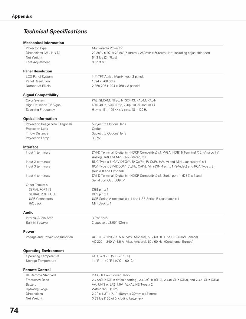
74
Appendix
Technical Specifications
Mechanical Information
Projector Type Multi-media ProjectorDimensions (W x H x D) 20.39" x 9.92" x 23.86" (518mm x 252mm x 606mm) (Not including adjustable feet)Net Weight 54.3 lbs (24.7kgs)Feet Adjustment 0˚ to 3.65˚
Panel Resolution
LCD Panel System 1.4" TFT Active Matrix type, 3 panelsPanel Resolution 1024 x 768 dotsNumber of Pixels 2,359,296 (1024 x 768 x 3 panels)
Signal Compatibility
Color System PAL, SECAM, NTSC, NTSC4.43, PAL-M, PAL-NHigh Definition TV Signal 480i, 480p, 575i, 575p, 720p, 1035i, and 1080iScanning Frequency H-sync. 15 ~ 120 KHz, V-sync. 48 ~ 120 Hz
Optical Information
Projection Image Size (Diagonal) Subject to Optional lensProjection Lens OptionThrow Distance Subject to Optional lensProjection Lamp 300W
Interface
Input 1 terminals DVI-D Terminal (Digital in) (HDCP Compatible) x1, (VGA) HDB15 Terminal X 2 (Analog In/ Analog Out) and Mini Jack (stereo) x 1
Input 2 terminals BNC Type x 5 (G/ VIDEO/Y, B/ Cb/Pb, R/ Cr/Pr, H/V, V) and Mini Jack (stereo) x 1Input 3 terminals RCA Type x 3 (VIDEO/Y, Cb/Pb, Cr/Pr), Mini DIN 4 pin x 1 (S-Video) and RCA Type x 2
(Audio R and L(mono))Input 4 terminals DVI-D Terminal (Digital in) (HDCP Compatible) x1, Serial port In (DB9) x 1 and
Serial port Out (DB9) x1Other Terminals
SERIAL PORT IN DB9 pin x 1SERIAL PORT OUT DB9 pin x 1USB Connectors USB Series A receptacle x 1 and USB Series B receptacle x 1R/C Jack Mini Jack x 1
Audio
Internal Audio Amp 3.0W RMSBuilt-in Speaker 2 speaker, ø2.05" (52mm)
Power
Voltage and Power Consumption AC 100 ~ 120 V (9.5 A Max. Ampere), 50 / 60 Hz (The U.S.A and Canada)AC 200 ~ 240 V (4.5 A Max. Ampere), 50 / 60 Hz (Continental Europe)
Operating Environment
Operating Temperature 41 ˚F ~ 95 ˚F (5 ˚C ~ 35 ˚C)Storage Temperature 14 ˚F ~ 140 ˚F (-10˚C ~ 60 ˚C)
Remote Control
RF Remote Standard 2.4 GHz Low Power Radio Frequency Band 2.472GHz (CH1: default setting), 2.403GHz (CH2), 2.446 GHz (CH3), and 2.421GHz (CH4)Battery AA, UM3 or LR6 1.5V ALKALINE Type x 2Operating Range Within 32.8' (10m)Dimensions 2.0” x 1.2” x 7.1” (50mm x 30mm x 181mm)Net Weight 0.33 lbs (150 g) (including batteries)
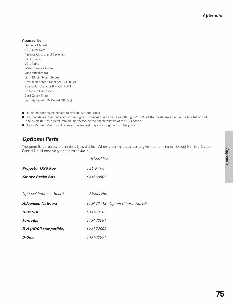
75
Appendix
Model No.
Projector USB Key : EUB-100
Smoke Resist Box : AH-69601
Optional Interface Board Model No.
Advanced Network : AH-72143 (Option Control No. 06)
Dual SDI : AH-72162
Faroudja : AH-72091
DVI (HDCP compatible) : AH-72003
D-Sub : AH-72031
The parts listed below are optionally available. When ordering those parts, give the item name, Model No. and OptionControl No. (if necessary) to the sales dealer.
Optional Parts
Accessories
Owner's ManualAC Power CordRemote Control and BatteriesDVI-D CableVGA CableWired Remote CableLens Attachment Light Block Plates (2types)Advanced Screen Manager (CD-ROM)Real Color Manager Pro (CD-ROM)Protective Dust CoverCord Cover StrapSecurity Label (PIN Code/USB Key)
● The specifications are subject to change without notice.● LCD panels are manufactured to the highest possible standards. Even though 99.99% of the pixels are effective, a tiny fraction of
the pixels (0.01% or less) may be ineffective by the characteristics of the LCD panels.● The On-Screen Menu and figures in this manual may differ slightly from the product.
Ap
pendix
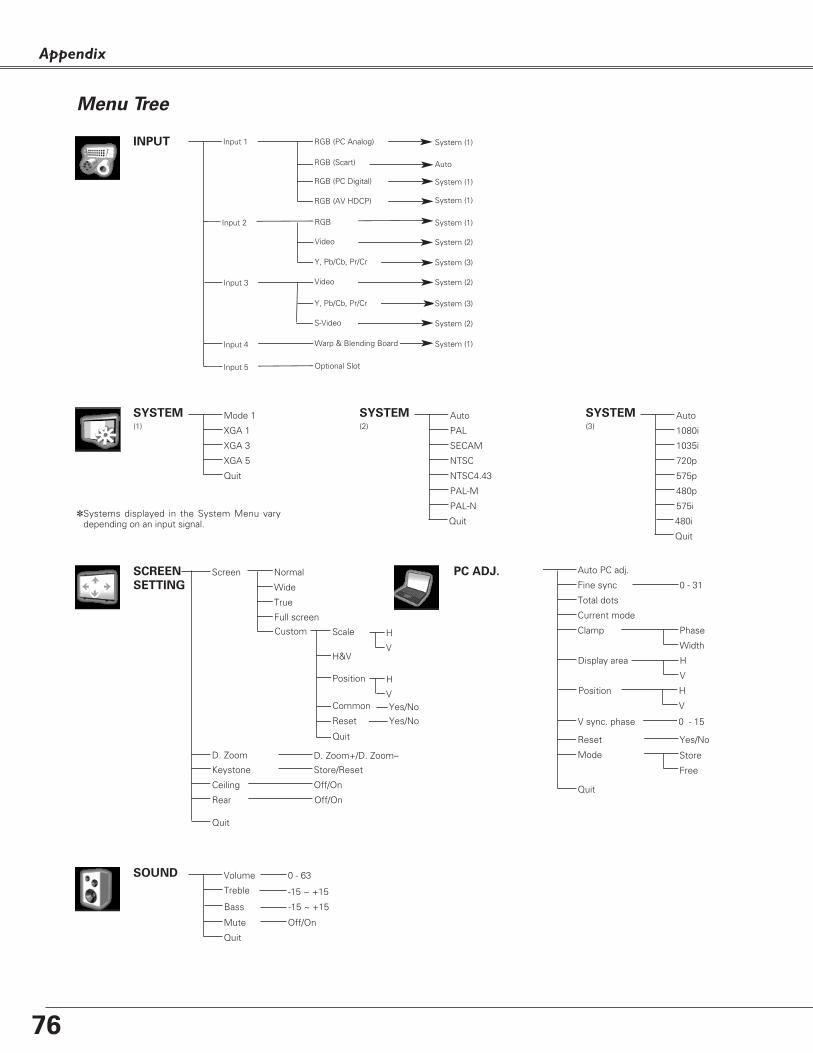
76
Appendix
System (1)
Input 2
Video
System (1)
Input 1
RGB
INPUT
(2)
SYSTEMSYSTEM
XGA 5
Mode 1
XGA 1
XGA 3
Auto PC adj.
Fine sync
Total dots
Current mode
Clamp
Position
Display area
Store
Quit
0 - 31
V
Yes/No
(1)
SECAM
NTSC
Auto
PAL
PAL-M
PAL-N
NTSC4.43
Quit
H
Reset
System (2)
Input 3 System (2)
System (3)
System (2)
Auto
Mode
Menu Tree
RGB (PC Analog)
RGB (Scart)
RGB (PC Digital) System (1)
RGB (AV HDCP) System (1)
Video
Y, Pb/Cb, Pr/Cr
Y, Pb/Cb, Pr/Cr System (3)
S-Video
Input 4 Warp & Blending Board
Input 5 Optional Slot
Quit
✽Systems displayed in the System Menu varydepending on an input signal.
SCREEN
SETTING
Screen
Wide
True
Normal
Scale
Position
Full screen
H
V
H
V
PC ADJ.
Off/OnCeiling
Off/OnRear
Quit
D. Zoom+/D. Zoom–
Keystone
Width
Phase
V
H
0 - 15
SOUND
Mute
Quit
Volume
Off/On
0 - 63
Treble -15 ~ +15
Bass -15 ~ +15
Custom
H&V
Common
Reset Yes/No
Quit
D. Zoom
(3)
SYSTEM
1035i
720p
Auto
1080i
480p
575i
575p
480i
System (1)
Quit
V sync. phase
Yes/No
Store/Reset Free
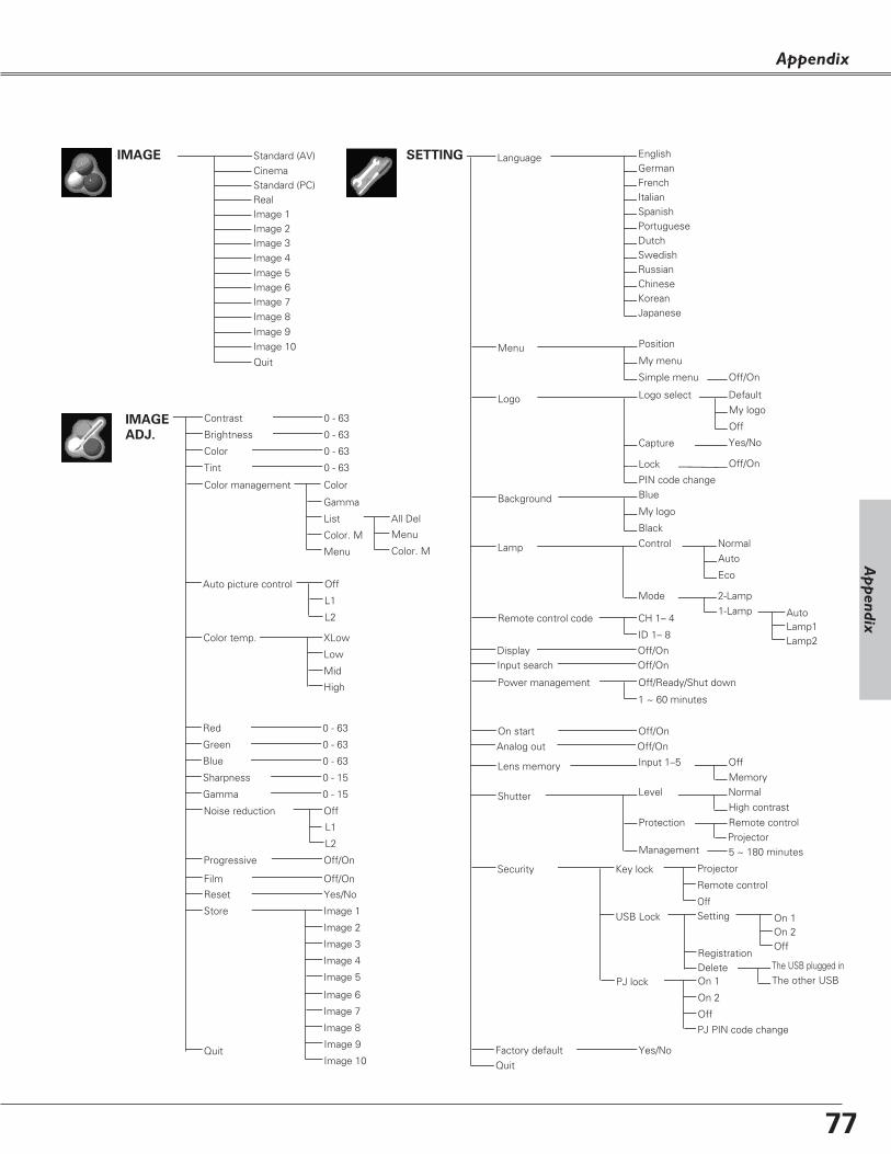
77
Appendix
LanguageSETTING
Power management
Remote control code
Key lock
Contrast
Brightness
Color
Red
Green
Blue
Sharpness
Store
Quit
0 - 63
0 - 63
0 - 63
0 - 63
0 - 63
0 - 63
0 - 15
Image 1
Image 2
Image 3
Image 4
Image 5
Tint 0 - 63
Gamma
Noise reduction
0 - 15
Off
Reset Yes/No
Film Off/On
Progressive Off/On
Color temp.
Image 6
Image 7
Image 8
Image 9
Image 10 Quit
Standard (AV)
Standard (PC)RealImage 1Image 2Image 3
IMAGE
Image 4
Cinema
Image 5Image 6Image 7Image 8Image 9Image 10
Quit
IMAGE
ADJ.
Color management
Gamma
All Del
Menu
Color. M
L1
Auto picture control
L2
Off
Low
Mid
XLow
L2
L1
Menu
Off/Ready/Shut down
CH 1– 4
Remote control
Off
Projector
ID 1– 8
1 ~ 60 minutes
Yes/No
EnglishGermanFrenchItalianSpanishPortugueseDutchSwedish
ChineseKoreanJapanese
Russian
Position
Simple menu
My menu
Factory default
Off/On
Logo Logo select
Capture Yes/No
Default
Off
My logo
Lock Off/On
PIN code change
Background Blue
Black
My logo
Lamp Control
Mode 2-Lamp1-Lamp
Normal
Eco
Auto
Display Off/OnInput search Off/On
On start Off/OnAnalog out Off/On
Lens memory Input 1–5 OffMemory
Shutter Level
Remote control
NormalHigh contrast
Protection
5 ~ 180 minutesManagement
Security
On 2
Off
PJ lock On 1
RegistrationDelete
USB Lock Setting
PJ PIN code change
On 2Off
On 1
Lamp1Lamp2
Auto
Color
Ap
pendix
High
Projector
The other USBThe USB plugged in
Color. M
Menu
List
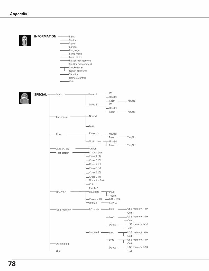
78
Appendix
Input
SignalScreenLanguageLamp modeLamp status
INFORMATION
Power management
System
Shutter managementSmoke resistOption filter timeSecurityRemote control Quit
LampSPECIAL
Quit
Filter
Lamp 1
Lamp 2
Option box
RS–232C Baud rate
Projector ID
9600
19200
Warning log
USB memory PC mode Save
Delete
Load
W
Reset
Hour(s)
Yes/NoW
Reset
Hour(s)
Yes/No
Fan control
Max
Hour(s)
Reset
Hour(s)
Reset
Yes/No
Yes/No
001 – 999
USB memory 1–10
Quit
Projector
USB memory 1–10
Quit
USB memory 1–10Quit
Image adj. Save
Load
USB memory 1–10Quit
USB memory 1–10
USB memory 1–10
Quit
Quit
Normal
Delete
Auto PC adj. Off/On
Test pattern Cross 1 (W)
Cross 3 (G)
Cross 2 (R)
Cross 4 (B)
Cross 6 (C)
Cross 5 (M)
Cross 7 (Y)
Color
Gradation 1~4
Flat 1~8
Default Yes/No
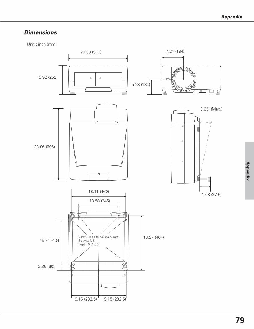
79
Appendix
20.39 (518)
23.86 (606)
Unit : inch (mm)
3.65˚ (Max.)
9.92 (252)
7.24 (184)
5.28 (134)
Dimensions
1.08 (27.5)
Ap
pendix
18.11 (460)
13.58 (345)
18.27 (464)
9.15 (232.5)9.15 (232.5)
15.91 (404)
2.36 (60)
Screw Holes for Ceiling MountScrews: M8Depth: 0.31(8.0)
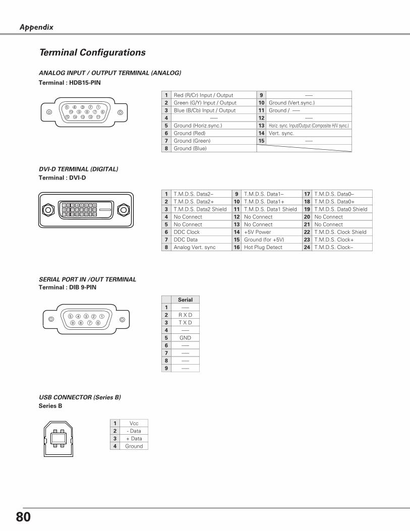
80
Appendix
Terminal Configurations
Terminal : DIB 9-PIN
35 4 2 1
79 8 6
SERIAL PORT IN /OUT TERMINAL
ANALOG INPUT / OUTPUT TERMINAL (ANALOG)
Terminal : HDB15-PIN
5 123410 9 678
15 14 13 1112
USB CONNECTOR (Series B)
-----R X DT X D-----
GND---------------
Serial
1
2
3
4
5
6
7
8
Red (R/Cr) Input / Output
Ground (Horiz.sync.)
Green (G/Y) Input / Output
-----Blue (B/Cb) Input / Output
Ground (Red)Ground (Green)Ground (Blue)
1
5
2
4
3
6
7
8
-----
Horiz. sync. Input/Output (Composite H/V sync.)
Ground (Vert.sync.)
-----Ground / -----
Vert. sync.-----
9
13
10
12
11
14
15
1917
21018
31119
41220
51321
61422
71523
81624
T.M.D.S. Data2–
No Connect
T.M.D.S. Data2+
No ConnectT.M.D.S. Data2 Shield
DDC ClockDDC DataAnalog Vert. sync
1
5
2
4
3
6
7
8
T.M.D.S. Data1–
No Connect
T.M.D.S. Data1+
No ConnectT.M.D.S. Data1 Shield
+5V PowerGround (for +5V)Hot Plug Detect
9
13
10
12
11
14
15
16
T.M.D.S. Data0–
No Connect
T.M.D.S. Data0+
No ConnectT.M.D.S. Data0 Shield
T.M.D.S. Clock ShieldT.M.D.S. Clock+T.M.D.S. Clock–
17
21
18
20
19
22
23
24
DVI-D TERMINAL (DIGITAL)
Terminal : DVI-D
-----9
Vcc- Data+ DataGround
1
2
3
4
2
3 4
1
Series B
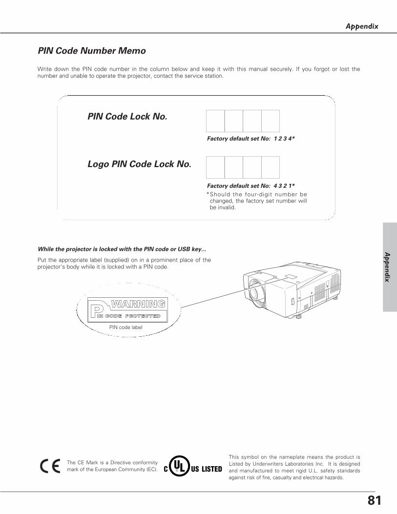
81
Appendix
Write down the PIN code number in the column below and keep it with this manual securely. If you forgot or lost thenumber and unable to operate the projector, contact the service station.
Factory default set No: 1 2 3 4*
Factory default set No: 4 3 2 1*
*Should the four-digit number bechanged, the factory set number willbe invalid.
PIN Code Lock No.
Logo PIN Code Lock No.
PIN Code Number Memo
Put the appropriate label (supplied) on in a prominent place of theprojector's body while it is locked with a PIN code.
While the projector is locked with the PIN code or USB key... Ap
pendix
This symbol on the nameplate means the product isListed by Underwriters Laboratories Inc. It is designedand manufactured to meet rigid U.L. safety standardsagainst risk of fire, casualty and electrical hazards.
The CE Mark is a Directive conformitymark of the European Community (EC).
PIN code label
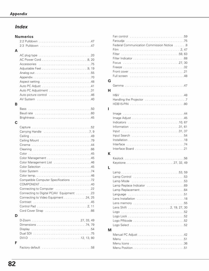
82
Appendix
Numerics
2:2 Pulldown . . . . . . . . . . . . . . . . . . . . . . . . . . . . . . .472:3 Pulldown . . . . . . . . . . . . . . . . . . . . . . . . . . . . . .47
A
AC plug type . . . . . . . . . . . . . . . . . . . . . . . . . . . . . . .20AC Power Cord . . . . . . . . . . . . . . . . . . . . . . . . . . .8, 20Accessories . . . . . . . . . . . . . . . . . . . . . . . . . . . . . . .75Adjustable Feet . . . . . . . . . . . . . . . . . . . . . . . . . . .9, 19Analog out . . . . . . . . . . . . . . . . . . . . . . . . . . . . . . . . .55Appendix . . . . . . . . . . . . . . . . . . . . . . . . . . . . . . . . . .70Aspect setting . . . . . . . . . . . . . . . . . . . . . . . . . . . . . .48Auto PC Adjust . . . . . . . . . . . . . . . . . . . . . . . . . . . . .41Auto PC Adjustment . . . . . . . . . . . . . . . . . . . . . . . . .31Auto picture control . . . . . . . . . . . . . . . . . . . . . . . . .46AV System . . . . . . . . . . . . . . . . . . . . . . . . . . . . . . . .40
B
Bass . . . . . . . . . . . . . . . . . . . . . . . . . . . . . . . . . . . . .50Baud rate . . . . . . . . . . . . . . . . . . . . . . . . . . . . . . . . .60Brightness . . . . . . . . . . . . . . . . . . . . . . . . . . . . . . . . .45
C
Capture . . . . . . . . . . . . . . . . . . . . . . . . . . . . . . . . . . .52Carrying Handle . . . . . . . . . . . . . . . . . . . . . . . . . . .7, 9Ceiling . . . . . . . . . . . . . . . . . . . . . . . . . . . . . . . . . . . .49Ceiling Mount . . . . . . . . . . . . . . . . . . . . . . . . . . . . . .79Cinema . . . . . . . . . . . . . . . . . . . . . . . . . . . . . . . . . . .44Cleaning . . . . . . . . . . . . . . . . . . . . . . . . . . . . . . . . . .66Color . . . . . . . . . . . . . . . . . . . . . . . . . . . . . . . . . . . . .45Color Management . . . . . . . . . . . . . . . . . . . . . . . . . .45Color Management List . . . . . . . . . . . . . . . . . . . . . .46Color Selection . . . . . . . . . . . . . . . . . . . . . . . . . . . . .45Color System . . . . . . . . . . . . . . . . . . . . . . . . . . . . . .74Color temp. . . . . . . . . . . . . . . . . . . . . . . . . . . . . . . . .46Compatible Computer Specifications . . . . . . . . . . . .72COMPONENT . . . . . . . . . . . . . . . . . . . . . . . . . . . . . .40Connecting to Computer . . . . . . . . . . . . . . . . . . . . .22Connecting to Digital PC/AV Equipment . . . . . . . . .23Connecting to Video Equipment . . . . . . . . . . . . .24, 25Contrast . . . . . . . . . . . . . . . . . . . . . . . . . . . . . . . . . .45Control Pad . . . . . . . . . . . . . . . . . . . . . . . . . . . . . .2, 11Cord Cover Strap . . . . . . . . . . . . . . . . . . . . . . . . . . .66
D
D-Zoom . . . . . . . . . . . . . . . . . . . . . . . . . . . . .27, 33, 49Dimensions . . . . . . . . . . . . . . . . . . . . . . . . . . . . .74, 79Display . . . . . . . . . . . . . . . . . . . . . . . . . . . . . . . . . . .54Dual SDI . . . . . . . . . . . . . . . . . . . . . . . . . . . . . . . . . .75DVI-D . . . . . . . . . . . . . . . . . . . . . . . . . . . . . .12, 13, 80
F
Factory default . . . . . . . . . . . . . . . . . . . . . . . . . . . . .58
Fan control . . . . . . . . . . . . . . . . . . . . . . . . . . . . . . . .59Faroudja . . . . . . . . . . . . . . . . . . . . . . . . . . . . . . . . . .75Federal Communication Commission Notice . . . . . . .8Film . . . . . . . . . . . . . . . . . . . . . . . . . . . . . . . . . . . .2, 47Filter . . . . . . . . . . . . . . . . . . . . . . . . . . . . . . . . . .59, 63Filter Indicator . . . . . . . . . . . . . . . . . . . . . . . . . . . . . .68Focus . . . . . . . . . . . . . . . . . . . . . . . . . . . . . . . . .27, 30Freeze . . . . . . . . . . . . . . . . . . . . . . . . . . . . . . . . . . . .32Front cover . . . . . . . . . . . . . . . . . . . . . . . . . . . . . . . .21Full screen . . . . . . . . . . . . . . . . . . . . . . . . . . . . . . . .48
G
Gamma . . . . . . . . . . . . . . . . . . . . . . . . . . . . . . . . . . .47
H
H&V . . . . . . . . . . . . . . . . . . . . . . . . . . . . . . . . . . . . .48Handling the Projector . . . . . . . . . . . . . . . . . . . . . . . .7HDB15-PIN . . . . . . . . . . . . . . . . . . . . . . . . . . . . . . . .80
I
Image . . . . . . . . . . . . . . . . . . . . . . . . . . . . . . . . . . . .44Image Adjust . . . . . . . . . . . . . . . . . . . . . . . . . . . . . . .45Indicators . . . . . . . . . . . . . . . . . . . . . . . . . . . . . .10, 67Information . . . . . . . . . . . . . . . . . . . . . . . . . . . . .31, 61Input . . . . . . . . . . . . . . . . . . . . . . . . . . . . . . . . . .31, 37Input Search . . . . . . . . . . . . . . . . . . . . . . . . . . . . . . .54Installation . . . . . . . . . . . . . . . . . . . . . . . . . . . . . . . . .18Interface . . . . . . . . . . . . . . . . . . . . . . . . . . . . . . . . . .74Interface Board . . . . . . . . . . . . . . . . . . . . . . . . . . . . .21
K
Keylock . . . . . . . . . . . . . . . . . . . . . . . . . . . . . . . . . . .56Keystone . . . . . . . . . . . . . . . . . . . . . . . . . . . .27, 32, 49
L
Lamp . . . . . . . . . . . . . . . . . . . . . . . . . . . . . . . . . .53, 59Lamp Control . . . . . . . . . . . . . . . . . . . . . . . . . . . . . .53Lamp Mode . . . . . . . . . . . . . . . . . . . . . . . . . . . . . . .53Lamp Replace Indicator . . . . . . . . . . . . . . . . . . . . . .69Lamp Replacement . . . . . . . . . . . . . . . . . . . . . . . . . .64Language . . . . . . . . . . . . . . . . . . . . . . . . . . . . . . . . .51Lens Installation . . . . . . . . . . . . . . . . . . . . . . . . . . . .18Lens memory . . . . . . . . . . . . . . . . . . . . . . . . . . . . . .55Lens Shift . . . . . . . . . . . . . . . . . . . . . . . . .2, 19, 27, 30Logo . . . . . . . . . . . . . . . . . . . . . . . . . . . . . . . . . . . . .52Logo Lock . . . . . . . . . . . . . . . . . . . . . . . . . . . . . . . . .52Logo PINcode . . . . . . . . . . . . . . . . . . . . . . . . . . . . . .52Logo Select . . . . . . . . . . . . . . . . . . . . . . . . . . . . . . . .52
M
Manual PC Adjust . . . . . . . . . . . . . . . . . . . . . . . . . . .42Menu . . . . . . . . . . . . . . . . . . . . . . . . . . . . . . . . . . . .51Menu Icons . . . . . . . . . . . . . . . . . . . . . . . . . . . . . . . .36Menu Position . . . . . . . . . . . . . . . . . . . . . . . . . . . . . .51
Index
83
Appendix
Menu Tree . . . . . . . . . . . . . . . . . . . . . . . . . . . . . . . .76Mouse Operation . . . . . . . . . . . . . . . . . . . . . . . .26, 34Moving the Projector . . . . . . . . . . . . . . . . . . . . . . . . .7Mute . . . . . . . . . . . . . . . . . . . . . . . . . . . . . . . . . . . . .50My Menu . . . . . . . . . . . . . . . . . . . . . . . . . . . . . . . . . .2My menu . . . . . . . . . . . . . . . . . . . . . . . . . . . . . . . . .51
N
Network Manager . . . . . . . . . . . . . . . . . . . . . . . . . . .75Noise reduction . . . . . . . . . . . . . . . . . . . . . . . . . . . . .47Normal . . . . . . . . . . . . . . . . . . . . . . . . . . . . . . . . . . .48
O
On start . . . . . . . . . . . . . . . . . . . . . . . . . . . . . . . . . . .54On-Screen Menu . . . . . . . . . . . . . . . . . . . . .34, 35, 36Option Control No. . . . . . . . . . . . . . . . . . . . . . . .21, 75Optional Parts . . . . . . . . . . . . . . . . . . . . . . . . . . . . . .75
P
P-Timer . . . . . . . . . . . . . . . . . . . . . . . . . . . . . . . . . . .32Panel Resolution . . . . . . . . . . . . . . . . . . . . . . . . . . . .74Parts Name . . . . . . . . . . . . . . . . . . . . . . . . . . . . . . . . .9PC Adjustment . . . . . . . . . . . . . . . . . . . . . . . . . . . . .41PC System . . . . . . . . . . . . . . . . . . . . . . . . . . . . . . . .39PIN code . . . . . . . . . . . . . . . . . . . . . . . . . . . .28, 57, 81PJ lock . . . . . . . . . . . . . . . . . . . . . . . . . . . . . . . . . . .57Position . . . . . . . . . . . . . . . . . . . . . . . . . . . . . . . . . . .48Positioning . . . . . . . . . . . . . . . . . . . . . . . . . . . . . .6, 18Power management . . . . . . . . . . . . . . . . . . . . . . . . .54Progressive . . . . . . . . . . . . . . . . . . . . . . . . . . . . . . . .47Projector Condition . . . . . . . . . . . . . . . . . . . . . . . . . .67Projector ID . . . . . . . . . . . . . . . . . . . . . . . . . . . . . . . .60
R
Radio Wave . . . . . . . . . . . . . . . . . . . . . . . . . . . . . . . .17READY indicator . . . . . . . . . . . . . . . . . . . . . . . . . . . .10Real . . . . . . . . . . . . . . . . . . . . . . . . . . . . . . . . . . . . . .44Rear . . . . . . . . . . . . . . . . . . . . . . . . . . . . . . . . . . . . .49Reference Buttons . . . . . . . . . . . . . . . . . . . . . . . . . .27Remote Control . . . . . . . . . . . . . . . . . . . . . .14, 16, 74Remote control . . . . . . . . . . . . . . . . . . . . . . . . . . . . .53Remote Control Battery Installation . . . . . . . . . . . . .17Remote Control Channel and ID . . . . . . . . . . . . . . . .16REPLACEMENT LAMP . . . . . . . . . . . . . . . . . . . .63, 65RESET . . . . . . . . . . . . . . . . . . . . . . . . . . . . . . . . . . . .13RS-232C . . . . . . . . . . . . . . . . . . . . . . . . . . . . . . . . . .60
S
Scale . . . . . . . . . . . . . . . . . . . . . . . . . . . . . . . . . . . . .48Scanning Frequency . . . . . . . . . . . . . . . . . . . . . . . . .74Screen . . . . . . . . . . . . . . . . . . . . . . . . . . . . . . . . .32, 48Security . . . . . . . . . . . . . . . . . . . . . . . . . . . . . . . . . . .56SERIAL PORT . . . . . . . . . . . . . . . . . . . . . . . . . . .13, 80
Setting . . . . . . . . . . . . . . . . . . . . . . . . . . . . . . . . . . .51Shutter . . . . . . . . . . . . . . . . . . . . . . . . . . . . . .2, 30, 55SHUTTER indicator . . . . . . . . . . . . . . . . . . . . . . . . . .10Shutter Indicator . . . . . . . . . . . . . . . . . . . . . . . . . . . .68Shutter level . . . . . . . . . . . . . . . . . . . . . . . . . . . . . . .55Shutter Management . . . . . . . . . . . . . . . . . . . . . . . .56Shutter protection . . . . . . . . . . . . . . . . . . . . . . . . . . .55Simple menu . . . . . . . . . . . . . . . . . . . . . . . . . . . . . . .51Smoke Resist Box . . . . . . . . . . . . . . . . . . . . . . . . . .75Sound . . . . . . . . . . . . . . . . . . . . . . . . . . . . . . . . . . . .50Speaker . . . . . . . . . . . . . . . . . . . . . . . . . . . . . . . . . . . .9Special . . . . . . . . . . . . . . . . . . . . . . . . . . . . . . . . . . .59Specifications . . . . . . . . . . . . . . . . . . . . . . . . . . . . . .74
T
Telecine . . . . . . . . . . . . . . . . . . . . . . . . . . . . . . . . . .47Terminal Configurations . . . . . . . . . . . . . . . . . . . . . .80Terminals . . . . . . . . . . . . . . . . . . . . . . . . . . . . . .12, 21Test pattern . . . . . . . . . . . . . . . . . . . . . . . . . . . . . . .60Top Control . . . . . . . . . . . . . . . . . . . . . . . . . . . . . .9, 11Treble . . . . . . . . . . . . . . . . . . . . . . . . . . . . . . . . . . . .50Troubleshooting . . . . . . . . . . . . . . . . . . . . . . . . . . . .70True . . . . . . . . . . . . . . . . . . . . . . . . . . . . . . . . . . . . . .48Turning Off the Projector . . . . . . . . . . . . . . . . . . . . .29Turning On the Projector . . . . . . . . . . . . . . . . . . . . .28
U
USB CONNECTOR . . . . . . . . . . . . . . . . . . . . . . . . . .80USB Key . . . . . . . . . . . . . . . . . . . . . . . . . . . . . . . . . .75USB lock . . . . . . . . . . . . . . . . . . . . . . . . . . . . . . . . . .56USB memory . . . . . . . . . . . . . . . . . . . . . . . . . . . . . .60
V
Volume . . . . . . . . . . . . . . . . . . . . . . . . . . . . . . . .33, 50
W
Warning log . . . . . . . . . . . . . . . . . . . . . . . . . . . . . . . .61WARNING TEMP indicator . . . . . . . . . . . . . . . . .10, 62Warp & Blending . . . . . . . . . . . . . . . . . . . . . . . . . .2, 23Wide . . . . . . . . . . . . . . . . . . . . . . . . . . . . . . . . . . . . .48Wired Remote Control . . . . . . . . . . . . . . . . . . . .16, 26
Z
Zoom . . . . . . . . . . . . . . . . . . . . . . . . . . . . . . . . . .27, 30
Ap
pendix

Part No. 610 315 6316 (1AA6P1P4593-- MM7B)Printed in Japan
© 2004 Eiki International, Inc.
A-key to better communications
U.S.A.EIKI International, Inc.30251 EsperanzaRancho Santa MargaritaCA 92688-2132U.S.A.Tel : 800-242-3454 (949)-457-0200 Fax : 800-457-3454 (949)-457-7878E-Mail : [email protected]
Canada
Deutschland & ÖsterreichEIKI Deutschland GmbHAm Frauwald 12 65510 IdsteinDeutschlandTel : 06126-9371-0 Fax : 06126-9371-14E-Mail : [email protected]
Eastern EuropeEIKI CZECH spol. s.r.o.Umelecká 15170 00 Praha 7 Czech RepublicTel : +42 02 20570024
+42 02 20571413 Fax : +42 02 20571411E-Mail : [email protected]
Japan & WorldwideEIKI Industrial Company Limited.4-12 Banzai-Cho, Kita-Ku, Osaka, 530-0028 JapanTel : +81-6-6311-9479 Fax : +81-6-6311-8486E-Mail : [email protected]
WorldWide Website http://www.eiki.com
ˆ
EIKI CANADA - Eiki International, Inc.P.O. Box 156, 310 First St. - Unit 2,Midland, ON, L4R 4K8, Canada Tel : 800-563-3454 (705)-527-4084Fax : 800-567-4069 (705)-527-4087E-Mail : [email protected]