Embed Size (px)
Citation preview

© 2010 Microchip Technology Inc. DS61160A
Multimedia Expansion BoardUser’s Guide
Note the following details of the code protection feature on Microchip devices:• Microchip products meet the specification contained in their particular Microchip Data Sheet.
• Microchip believes that its family of products is one of the most secure families of its kind on the market today, when used in the intended manner and under normal conditions.
• There are dishonest and possibly illegal methods used to breach the code protection feature. All of these methods, to our knowledge, require using the Microchip products in a manner outside the operating specifications contained in Microchip’s Data Sheets. Most likely, the person doing so is engaged in theft of intellectual property.
• Microchip is willing to work with the customer who is concerned about the integrity of their code.
• Neither Microchip nor any other semiconductor manufacturer can guarantee the security of their code. Code protection does not mean that we are guaranteeing the product as “unbreakable.”
Code protection is constantly evolving. We at Microchip are committed to continuously improving the code protection features of ourproducts. Attempts to break Microchip’s code protection feature may be a violation of the Digital Millennium Copyright Act. If such actsallow unauthorized access to your software or other copyrighted work, you may have a right to sue for relief under that Act.
Information contained in this publication regarding deviceapplications and the like is provided only for your convenienceand may be superseded by updates. It is your responsibility toensure that your application meets with your specifications.MICROCHIP MAKES NO REPRESENTATIONS ORWARRANTIES OF ANY KIND WHETHER EXPRESS ORIMPLIED, WRITTEN OR ORAL, STATUTORY OROTHERWISE, RELATED TO THE INFORMATION,INCLUDING BUT NOT LIMITED TO ITS CONDITION,QUALITY, PERFORMANCE, MERCHANTABILITY ORFITNESS FOR PURPOSE. Microchip disclaims all liabilityarising from this information and its use. Use of Microchipdevices in life support and/or safety applications is entirely atthe buyer’s risk, and the buyer agrees to defend, indemnify andhold harmless Microchip from any and all damages, claims,suits, or expenses resulting from such use. No licenses areconveyed, implicitly or otherwise, under any Microchipintellectual property rights.
DS61160A-page 2
Trademarks
The Microchip name and logo, the Microchip logo, dsPIC, KEELOQ, KEELOQ logo, MPLAB, PIC, PICmicro, PICSTART, PIC32 logo, rfPIC and UNI/O are registered trademarks of Microchip Technology Incorporated in the U.S.A. and other countries.
FilterLab, Hampshire, HI-TECH C, Linear Active Thermistor, MXDEV, MXLAB, SEEVAL and The Embedded Control Solutions Company are registered trademarks of Microchip Technology Incorporated in the U.S.A.
Analog-for-the-Digital Age, Application Maestro, CodeGuard, dsPICDEM, dsPICDEM.net, dsPICworks, dsSPEAK, ECAN, ECONOMONITOR, FanSense, HI-TIDE, In-Circuit Serial Programming, ICSP, Mindi, MiWi, MPASM, MPLAB Certified logo, MPLIB, MPLINK, mTouch, Octopus, Omniscient Code Generation, PICC, PICC-18, PICDEM, PICDEM.net, PICkit, PICtail, REAL ICE, rfLAB, Select Mode, Total Endurance, TSHARC, UniWinDriver, WiperLock and ZENA are trademarks of Microchip Technology Incorporated in the U.S.A. and other countries.
SQTP is a service mark of Microchip Technology Incorporated in the U.S.A.
All other trademarks mentioned herein are property of their respective companies.
© 2010, Microchip Technology Incorporated, Printed in the U.S.A., All Rights Reserved.
Printed on recycled paper.
ISBN: 978-1-60932-270-0Microchip received ISO/TS-16949:2002 certification for its worldwide
© 2010 Microchip Technology Inc.
headquarters, design and wafer fabrication facilities in Chandler and Tempe, Arizona; Gresham, Oregon and design centers in California and India. The Company’s quality system processes and procedures are for its PIC® MCUs and dsPIC® DSCs, KEELOQ® code hopping devices, Serial EEPROMs, microperipherals, nonvolatile memory and analog products. In addition, Microchip’s quality system for the design and manufacture of development systems is ISO 9001:2000 certified.
MULTIMEDIA EXPANSIONBOARD USER’S GUIDE
Table of Contents
Preface ........................................................................................................................... 5Chapter 1. Introduction
1.1 Kit Contents .................................................................................................. 111.2 Multimedia Features ..................................................................................... 11
Chapter 2. Hardware2.1 Power Supply ............................................................................................... 152.2 Starter Kit Connector .................................................................................... 162.3 Display ......................................................................................................... 192.4 microSD Card Slot ........................................................................................ 232.5 Joystick and Fire Button ............................................................................... 242.6 User-Controlled LEDs .................................................................................. 252.7 Accelerometer and Temperature Sensor ..................................................... 262.8 External Memory .......................................................................................... 272.9 24-bit Audio Codec ....................................................................................... 292.10 802.11 Wireless Connectivity ..................................................................... 322.11 I/O Expansion Connector ........................................................................... 332.12 CPLD .......................................................................................................... 34
Appendix A. Board Layout and SchematicsA.1 Multimedia Expansion Board Block Diagram ............................................... 37A.2 Multimedia Expansion Board Layout ........................................................... 38A.3 Multimedia Expansion Board Schematics .................................................... 40
Appendix B. Bill of Materials (BOM)Index ............................................................................................................................. 57Worldwide Sales and Service .................................................................................... 58
© 2010 Microchip Technology Inc. DS61160A-page 3

Multimedia Expansion Board User’s Guide
DS61160A-page 4 © 2010 Microchip Technology Inc.
MULTIMEDIA EXPANSIONBOARD USER’S GUIDE
Preface
INTRODUCTIONThis chapter contains general information that will be useful to know before using the starter kit. Items discussed in this chapter include:• Document Layout• Conventions Used in this Guide• Recommended Reading• The Microchip Web Site• Development Systems Customer Change Notification Service• Customer Support• Document Revision History
DOCUMENT LAYOUTThis user’s guide describes how to use the Multimedia Expansion Board and consists of the following chapters:• Chapter 1. “Introduction” provides a brief overview of each starter kit,
highlighting their features and uses. • Chapter 2. “Hardware” provides the hardware descriptions of each starter kit.• Appendix A. “Board Layout and Schematics” provides a block diagram, board
layouts and detailed schematics of each starter kit.
NOTICE TO CUSTOMERS
All documentation becomes dated, and this manual is no exception. Microchip tools and documentation are constantly evolving to meet customer needs, so some actual dialogs and/or tool descriptions may differ from those in this document. Please refer to our web site (www.microchip.com) to obtain the latest documentation available.
Documents are identified with a “DS” number. This number is located on the bottom of each page, in front of the page number. The numbering convention for the DS number is “DSXXXXXA”, where “XXXXX” is the document number and “A” is the revision level of the document.
For the most up-to-date information on development tools, see the MPLAB® IDE online help. Select the Help menu, and then Topics to open a list of available online help files.
© 2010 Microchip Technology Inc. DS61160A-page 5
Multimedia Expansion Board User’s Guide
CONVENTIONS USED IN THIS GUIDEThis manual uses the following documentation conventions:
DOCUMENTATION CONVENTIONSDescription Represents Examples
Arial font:Italic characters Referenced books MPLAB® IDE User’s Guide
Emphasized text ...is the only compiler...Initial caps A window the Output window
A dialog the Settings dialogA menu selection select Enable Programmer
Quotes A field name in a window or dialog “Save project before build”Underlined, italic text with right angle bracket
A menu path File>Save
Bold characters A dialog button Click OKA tab Click the Power tab
Text in angle brackets < > A key on the keyboard Press <Enter>, <F1>Courier New font:Plain Courier New Sample source code #define START
Filenames autoexec.bat
File paths C:\mcc18\h
Keywords _asm, _endasm, static
Command-line options -Opa+, -Opa-
Bit values 0, 1
Constants (in source code) 0xFF, ‘A’
Italic Courier New A variable argument file.o, where file can be any valid filename
Square brackets [ ] Optional arguments mcc18 [options] file [options]
Curly brackets and pipe character: { | }
Choice of mutually exclusive arguments; an OR selection
errorlevel {0|1}
Ellipses... Replaces repeated text var_name [, var_name...]
Represents code supplied by user void main (void){ ...}
DS61160A-page 6 © 2010 Microchip Technology Inc.
Preface
RECOMMENDED READINGThe following Microchip documents are available and recommended as supplemental reference resources.
Release Notes for the Multimedia Expansion Board For the latest information, Microchip has a dedicated web page for the Multimedia Expansion Board, which can be accessed at: http://www.microchip.com/PIC32
PIC32MX3XX/4XX Family Data Sheet (DS61143) and PIC32MX5XX/6XX/7XX Family Data Sheet (DS61156)Refer these documents for detailed information on PIC32 32-bit devices. Reference information found in these data sheets includes:• Device memory maps• Device pinout and packaging details• Device electrical specifications• List of peripherals included on the devices
MPLAB® C Compiler for PIC32 User’s Guide (DS51686)This document, formerly the MPLAB C32 C Compiler for PIC32 User’s Guide, details the use of Microchip’s MPLAB C Compiler for PIC32 to develop an application.
MPLAB® IDE User’s Guide (DS51519)Refer this document for more information pertaining to the installation and implementation of the MPLAB IDE software, as well as the MPLAB Editor and MPLAB SIM Simulator software that are included with it.
THE MICROCHIP WEB SITEMicrochip provides online support through our web site at http://www.microchip.com. This web site makes files and information easily available to customers. Accessible by most Internet browsers, the web site contains the following information:• Product Support – Data sheets and errata, application notes and sample
programs, design resources, user’s guides and hardware support documents, latest software releases and archived software
• General Technical Support – Frequently Asked Questions (FAQs), technical support requests, online discussion groups, Microchip consultant program member listings
• Business of Microchip – Product selector and ordering guides, latest Microchip press releases, listings of seminars and events; and listings of Microchip sales offices, distributors and factory representatives
© 2010 Microchip Technology Inc. DS61160A-page 7
Multimedia Expansion Board User’s Guide
DEVELOPMENT SYSTEMS CUSTOMER CHANGE NOTIFICATION SERVICEMicrochip’s customer notification service helps keep customers current on Microchip products. Subscribers will receive e-mail notification whenever there are changes, updates, revisions or errata related to a specified product family or development tool of interest.To register, access the Microchip web site at http://www.microchip.com, click Customer Change Notification and follow the registration instructions.The Development Systems product group categories are:• Compilers – The latest information on Microchip C compilers and other language
tools. These include the MPLAB C18 and MPLAB C30 C compilers, and MPLAB C Compiler for PIC32; ASM32, MPASM™ and MPLAB ASM30 assemblers; MPLINK™, and MPLAB LINK30, MPLAB LINK32 object linkers; and MPLIB™ and MPLAB LIB30 object librarians.
• Emulators – The latest information on Microchip in-circuit emulators. This includes the MPLAB REAL ICE™ and MPLAB ICE 2000 in-circuit emulators.
• In-Circuit Debuggers – The latest information on the Microchip in-circuit debuggers. This includes the MPLAB ICD 3 and PICkit™ 2.
• MPLAB IDE – The latest information on Microchip MPLAB IDE, the Windows® Integrated Development Environment for development systems tools. This list is focused on the MPLAB IDE, MPLAB IDE Project Manager, MPLAB Editor and MPLAB SIM simulator, as well as general editing and debugging features.
• Programmers – The latest information on Microchip programmers. These include the MPLAB PM3 device programmer and the PICSTART® Plus, PICkit™ 1 and PICkit 2 development programmers.
CUSTOMER SUPPORTSeveral channels are available to assist the users of Microchip products:• Distributor or Representative• Local Sales Office• Field Application Engineer (FAE)• Technical Support• Development Systems Information LineCustomers should contact their distributor, representative, or FAE for support. Local sales offices are also available to help customers. A list of sales offices and locations is included in the back of this document.Technical support is available through our web site at http://support.microchip.com.
DS61160A-page 8 © 2010 Microchip Technology Inc.
Preface
DOCUMENT REVISION HISTORY
Revision A (June 2010)This is the initial release of the Multimedia Expansion Board User’s Guide.
© 2010 Microchip Technology Inc. DS61160A-page 9

Multimedia Expansion Board User’s Guide
NOTES:
DS61160A-page 10 © 2010 Microchip Technology Inc.
MULTIMEDIA EXPANSIONBOARD USER’S GUIDE
Chapter 1. Introduction
Thank you for purchasing Microchip Technology Multimedia Expansion Board. This compact, highly versatile board can be connected to any PIC32MX starter kit for the purpose of developing multimedia applications, such as audio, graphics and touch screen.This chapter includes the following topics:• Kit Contents• Multimedia Features
1.1 KIT CONTENTSThe Multimedia Expansion Board kit contains the following items:• Multimedia Expansion Board• Multimedia Expansion Board Information Sheet
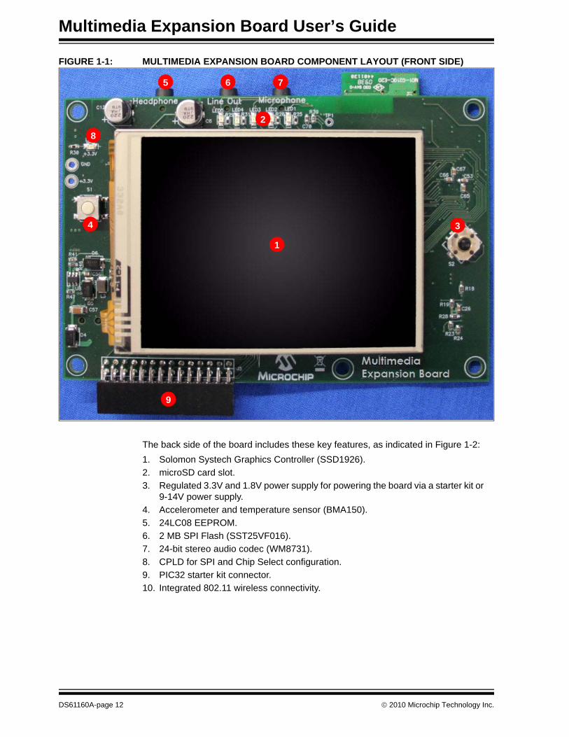
1.2 MULTIMEDIA FEATURESThe component layout of the Multimedia Expansion Board is shown in Figure 1-1 (front side) and Figure 1-2 (back side). The front side of the board includes these key features, as shown in Figure 1-1:1. 3.2 inch (8.1 cm) QVGA touch screen display with backlight.2. Five user-controlled LEDs.3. Four-way joystick (S2).4. Fire button (S1).5. Headphone jack.6. Line output jack.7. Microphone input jack.8. Power LED.9. I/O expansion connector.
© 2010 Microchip Technology Inc. DS61160A-page 11
Multimedia Expansion Board User’s Guide
FIGURE 1-1: MULTIMEDIA EXPANSION BOARD COMPONENT LAYOUT (FRONT SIDE)
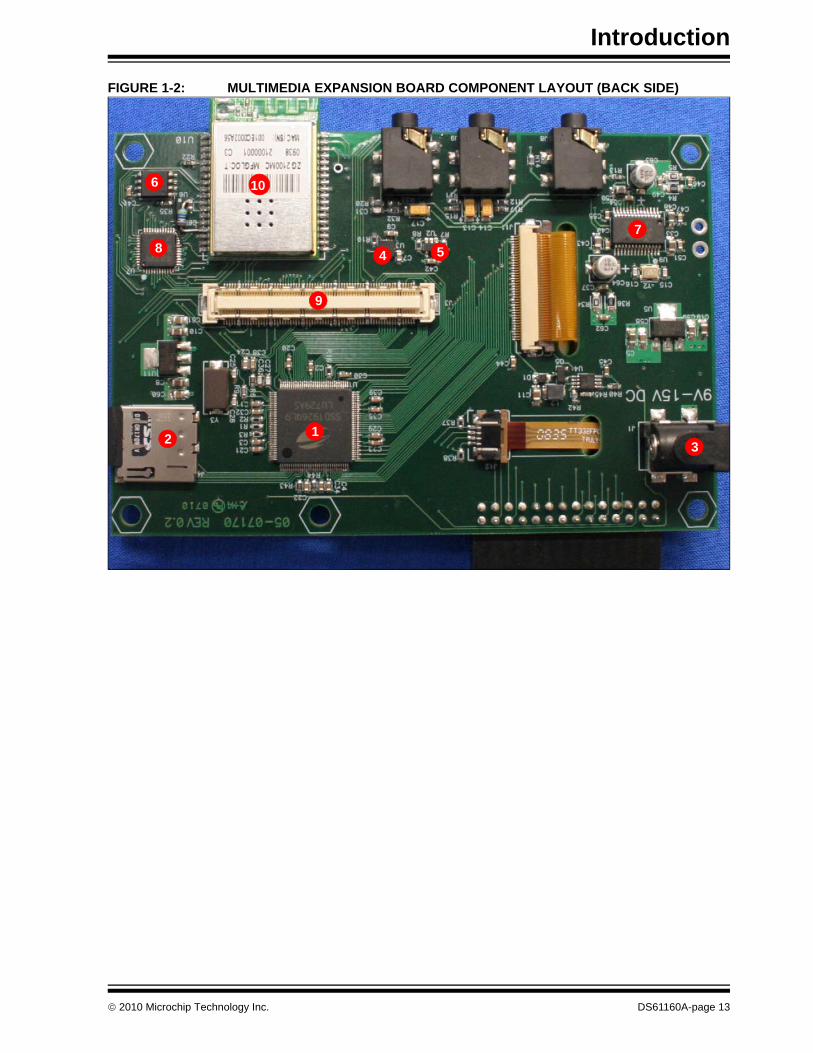
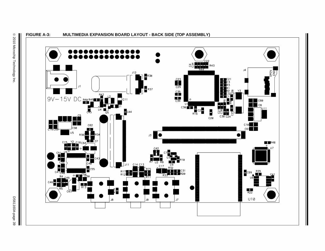
The back side of the board includes these key features, as indicated in Figure 1-2:1. Solomon Systech Graphics Controller (SSD1926).2. microSD card slot.3. Regulated 3.3V and 1.8V power supply for powering the board via a starter kit or
9-14V power supply.4. Accelerometer and temperature sensor (BMA150).5. 24LC08 EEPROM.6. 2 MB SPI Flash (SST25VF016).7. 24-bit stereo audio codec (WM8731).8. CPLD for SPI and Chip Select configuration.9. PIC32 starter kit connector.10. Integrated 802.11 wireless connectivity.
1
5 6 7
2
34
8
9
DS61160A-page 12 © 2010 Microchip Technology Inc.
Introduction
FIGURE 1-2: MULTIMEDIA EXPANSION BOARD COMPONENT LAYOUT (BACK SIDE)
2
10
3
9
1
4 5
6
78
© 2010 Microchip Technology Inc. DS61160A-page 13

Multimedia Expansion Board User’s Guide
NOTES:
DS61160A-page 14 © 2010 Microchip Technology Inc.
MULTIMEDIA EXPANSIONBOARD USER’S GUIDE
Chapter 2. Hardware
This chapter describes the hardware used in the Multimedia Expansion Board. Topics covered include:• Power Supply• Starter Kit Connector• Display • microSD Card Slot• Joystick and Fire Button• User-Controlled LEDs• Accelerometer and Temperature Sensor• External Memory• 24-bit Audio Codec• 802.11 Wireless Connectivity• I/O Expansion Connector• CPLD
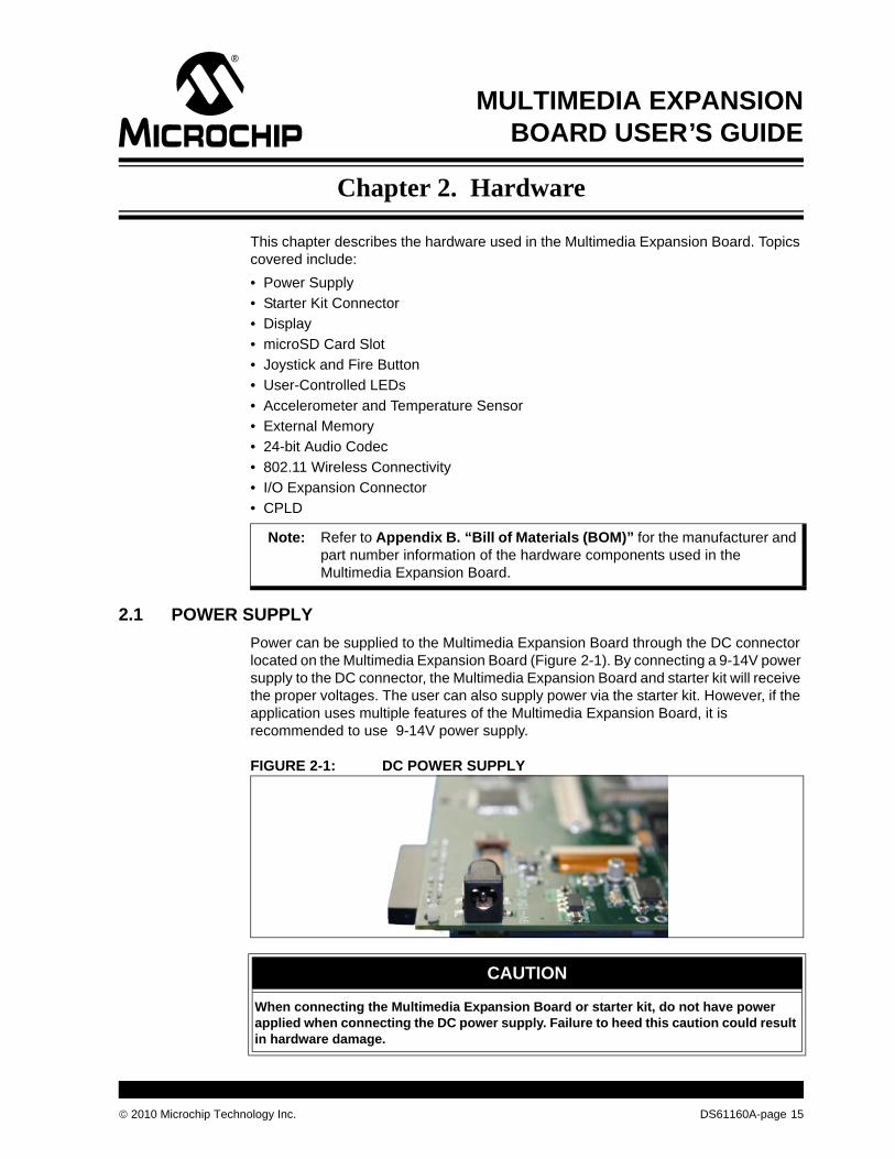
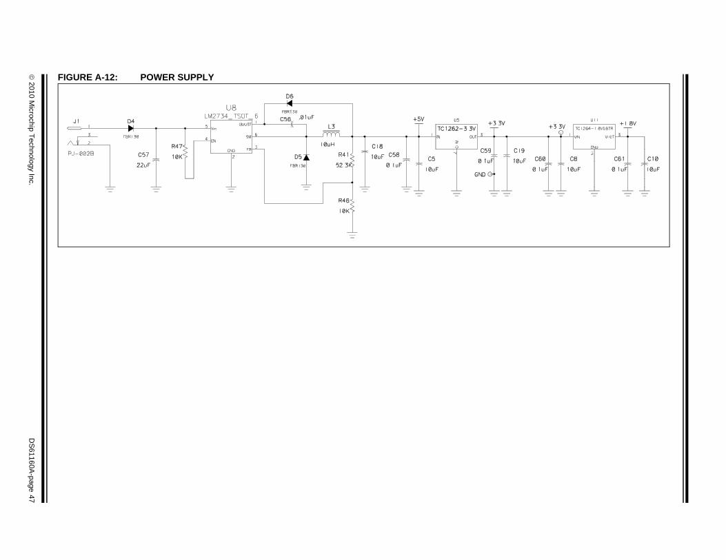
2.1 POWER SUPPLYPower can be supplied to the Multimedia Expansion Board through the DC connector located on the Multimedia Expansion Board (Figure 2-1). By connecting a 9-14V power supply to the DC connector, the Multimedia Expansion Board and starter kit will receive the proper voltages. The user can also supply power via the starter kit. However, if the application uses multiple features of the Multimedia Expansion Board, it is recommended to use 9-14V power supply.
FIGURE 2-1: DC POWER SUPPLY
Note: Refer to Appendix B. “Bill of Materials (BOM)” for the manufacturer and part number information of the hardware components used in the Multimedia Expansion Board.
CAUTION
When connecting the Multimedia Expansion Board or starter kit, do not have power applied when connecting the DC power supply. Failure to heed this caution could result in hardware damage.
© 2010 Microchip Technology Inc. DS61160A-page 15
Multimedia Expansion Board User’s Guide
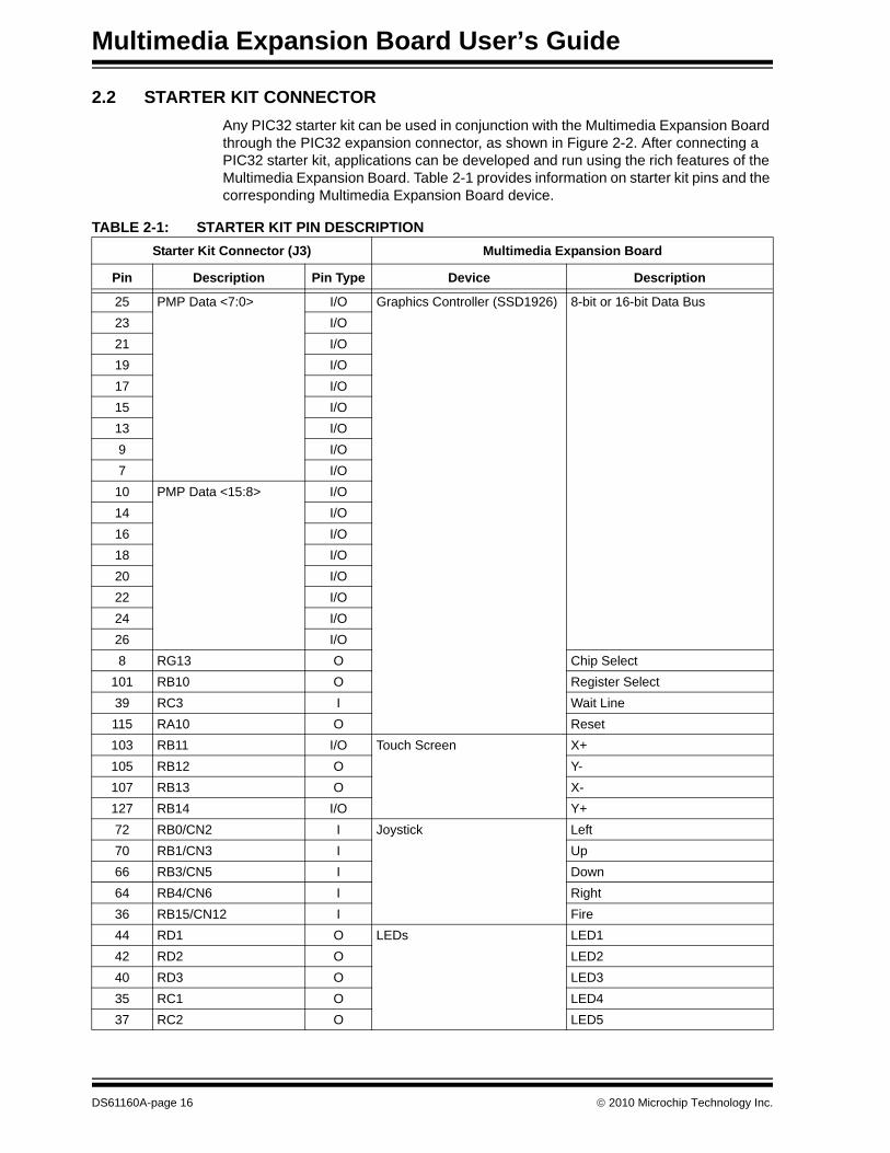
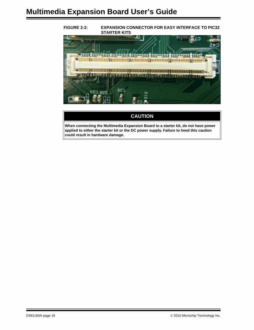
2.2 STARTER KIT CONNECTORAny PIC32 starter kit can be used in conjunction with the Multimedia Expansion Board through the PIC32 expansion connector, as shown in Figure 2-2. After connecting a PIC32 starter kit, applications can be developed and run using the rich features of the Multimedia Expansion Board. Table 2-1 provides information on starter kit pins and the corresponding Multimedia Expansion Board device.
TABLE 2-1: STARTER KIT PIN DESCRIPTIONStarter Kit Connector (J3) Multimedia Expansion Board
Pin Description Pin Type Device Description
25 PMP Data <7:0> I/O Graphics Controller (SSD1926) 8-bit or 16-bit Data Bus23 I/O21 I/O19 I/O17 I/O15 I/O13 I/O9 I/O7 I/O
10 PMP Data <15:8> I/O14 I/O16 I/O18 I/O20 I/O22 I/O24 I/O26 I/O8 RG13 O Chip Select
101 RB10 O Register Select39 RC3 I Wait Line115 RA10 O Reset103 RB11 I/O Touch Screen X+105 RB12 O Y-107 RB13 O X-127 RB14 I/O Y+72 RB0/CN2 I Joystick Left70 RB1/CN3 I Up66 RB3/CN5 I Down64 RB4/CN6 I Right36 RB15/CN12 I Fire44 RD1 O LEDs LED142 RD2 O LED240 RD3 O LED335 RC1 O LED437 RC2 O LED5
DS61160A-page 16 © 2010 Microchip Technology Inc.
Hardware
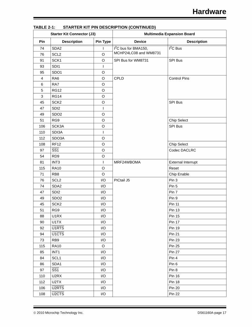
74 SDA2 I I2C bus for BMA150, MCHP24LC08 and WM8731
I2C Bus76 SCL2 O91 SCK1 O SPI Bus for WM8731 SPI Bus93 SDI1 I95 SDO1 O4 RA6 O CPLD Control Pins6 RA7 O5 RG12 O3 RG14 O
45 SCK2 O SPI Bus47 SDI2 I49 SDO2 O51 RG9 O Chip Select
106 SCK3A O SPI Bus110 SDI3A I112 SDO3A O108 RF12 O Chip Select97 SS1 O Codec DACLRC54 RD9 O81 INT3 I MRF24WBOMA External Interrupt115 RA10 O Reset71 RB8 O Chip Enable76 SCL2 I/O PICtail J5 Pin 374 SDA2 I/O Pin 547 SDI2 I/O Pin 749 SDO2 I/O Pin 945 SCK2 I/O Pin 1151 RG9 I/O Pin 1388 U1RX I/O Pin 1590 U1TX I/O Pin 1792 U1RTS I/O Pin 1994 U1CTS I/O Pin 2173 RB9 I/O Pin 23115 RA10 O Pin 2585 INT1 I/O Pin 2784 SCL1 I/O Pin 486 SDA1 I/O Pin 697 SS1 I/O Pin 8110 U2RX I/O Pin 16112 U2TX I/O Pin 18106 U2RTS I/O Pin 20108 U2CTS I/O Pin 22
TABLE 2-1: STARTER KIT PIN DESCRIPTION (CONTINUED)Starter Kit Connector (J3) Multimedia Expansion Board
Pin Description Pin Type Device Description
© 2010 Microchip Technology Inc. DS61160A-page 17
Multimedia Expansion Board User’s Guide
FIGURE 2-2: EXPANSION CONNECTOR FOR EASY INTERFACE TO PIC32 STARTER KITS
CAUTION
When connecting the Multimedia Expansion Board to a starter kit, do not have power applied to either the starter kit or the DC power supply. Failure to heed this caution could result in hardware damage.
DS61160A-page 18 © 2010 Microchip Technology Inc.
Hardware
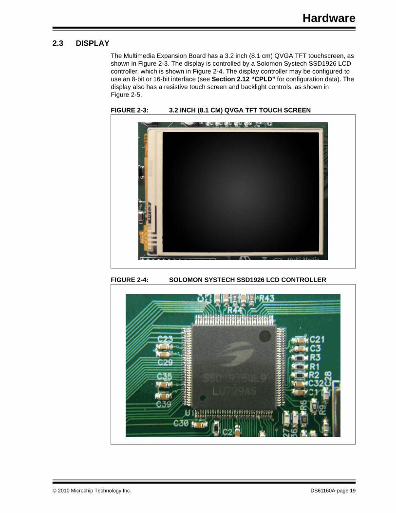
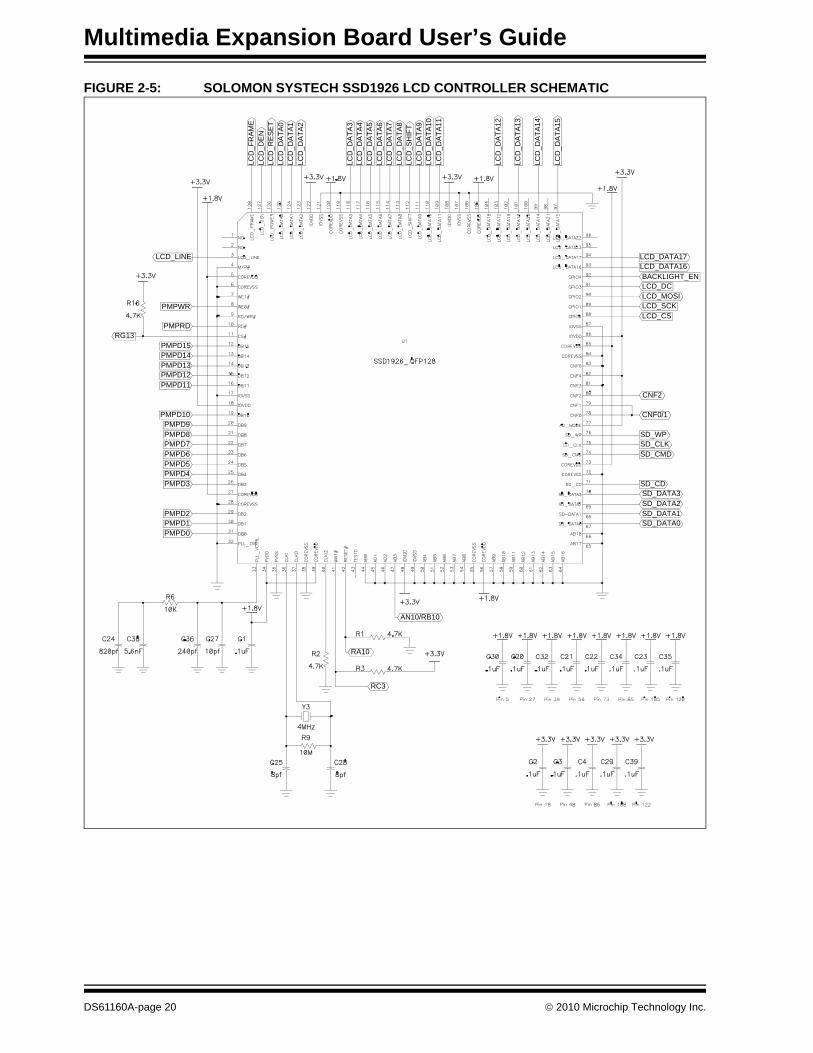
2.3 DISPLAY The Multimedia Expansion Board has a 3.2 inch (8.1 cm) QVGA TFT touchscreen, as shown in Figure 2-3. The display is controlled by a Solomon Systech SSD1926 LCD controller, which is shown in Figure 2-4. The display controller may be configured to use an 8-bit or 16-bit interface (see Section 2.12 “CPLD” for configuration data). The display also has a resistive touch screen and backlight controls, as shown in Figure 2-5.
FIGURE 2-3: 3.2 INCH (8.1 CM) QVGA TFT TOUCH SCREEN
FIGURE 2-4: SOLOMON SYSTECH SSD1926 LCD CONTROLLER
© 2010 Microchip Technology Inc. DS61160A-page 19
Multimedia Expansion Board User’s Guide
FIGURE 2-5: SOLOMON SYSTECH SSD1926 LCD CONTROLLER SCHEMATIC
LCD
_FR
AM
E
LCD
_RE
SE
TLC
D_D
ATA
0
LCD
_DA
TA2
LCD
_DA
TA4
LCD
_DA
TA5
LCD
_DA
TA7
LCD
_DA
TA8
LCD
_DA
TA9
LCD
_DA
TA10
LCD
_DA
TA13
LCD
_DA
TA14
RG13
PMPD1PMPD2
PMPD3
PMPD5PMPD6
PMPD8PMPD9
RC3
PMPD0
PMPD4
PMPD7
PMPRD
RA10
LCD
_DE
N
LCD
_DA
TA1
LCD
_DA
TA3
LCD
_DA
TA6
LCD
_SH
IFT
LCD
_DA
TA11
LCD
_DA
TA12
LCD
_DA
TA15
PMPD12PMPD13
PMPD15
PMPWR
LCD_LINE
AN10/RB10
SD_DATA0SD_DATA1
SD_DATA3SD_CD
SD_CMD
SD_WP
CNF2
LCD_CSLCD_SCK
LCD_DCBACKLIGHT_EN
LCD_DATA17
PMPD10
PMPD11
PMPD14
SD_DATA2
SD_CLK
CNF0/1
LCD_MOSI
LCD_DATA16
DS61160A-page 20 © 2010 Microchip Technology Inc.
Hardware
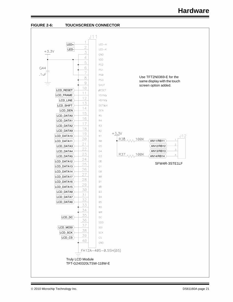
FIGURE 2-6: TOUCHSCREEN CONNECTOR
LCD_SCK
LCD_MOSI
LCD_DC
LCD_DATA6
LCD_DATA7
LCD_DATA15
LCD_DATA16
LCD_DATA14
LCD_DATA13
LCD_DATA5
LCD_DATA4
LCD_DATA11
LCD_DATA10
LCD_DATA2
LCD_DATA1
LCD_DEN
LCD_SHIFT
LCD_FRAME
LCD_RESET
LED-
LED+
LCD_CS
LCD_DATA8
LCD_DATA17
LCD_DATA12
LCD_DATA3
LCD_DATA9
LCD_DATA0
LCD_LINE
AN13/RB13
AN12/RB12
AN14/RB14
AN11/RB11
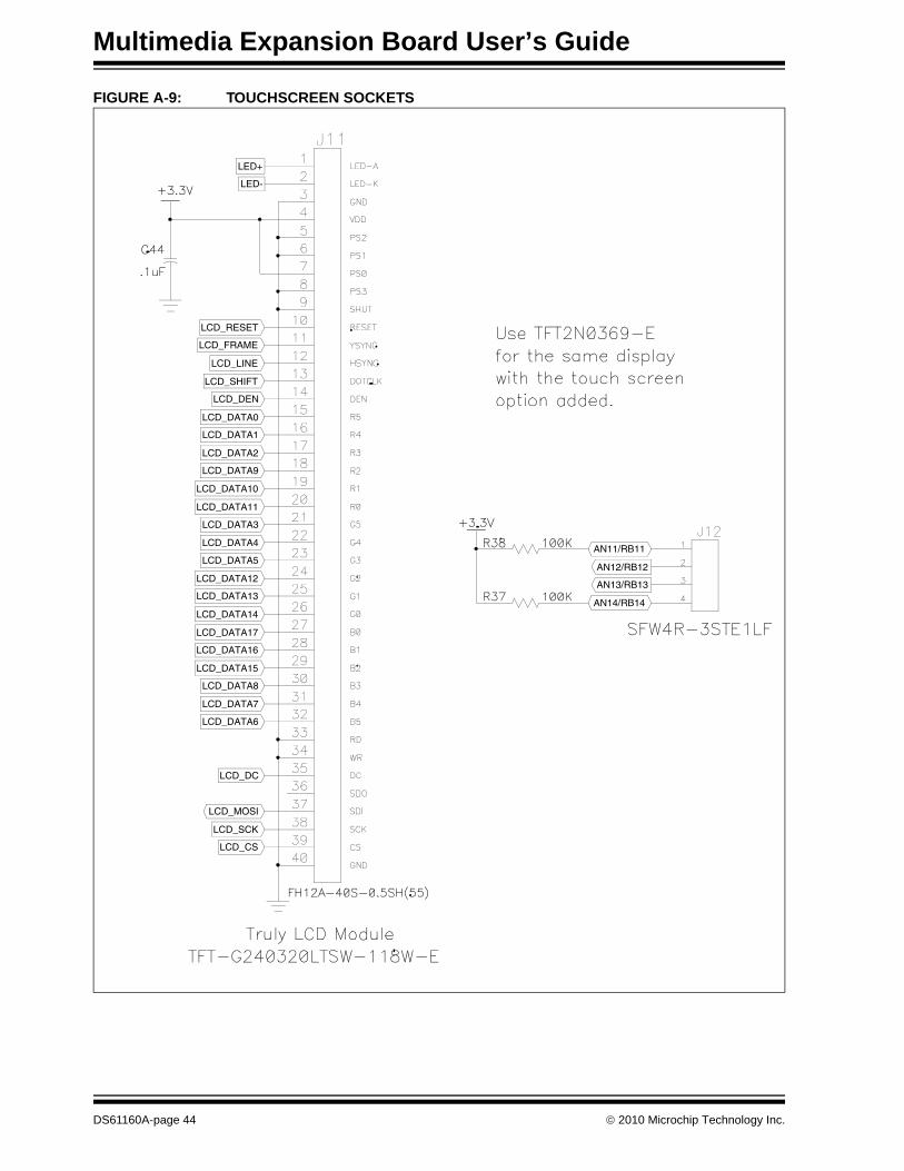
Use TFT2N0369-E for the same display with the touch screen option added.
SFW4R-3STE1LF
Truly LCD Module TFT-G240320LTSW-118W-E
© 2010 Microchip Technology Inc. DS61160A-page 21
Multimedia Expansion Board User’s Guide
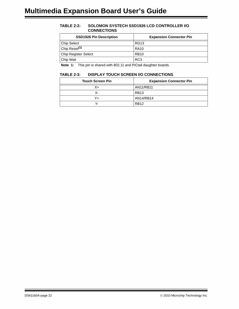
TABLE 2-2: SOLOMON SYSTECH SSD1926 LCD CONTROLLER I/O CONNECTIONS
TABLE 2-3: DISPLAY TOUCH SCREEN I/O CONNECTIONS
SSD1926 Pin Description Expansion Connector Pin
Chip Select RG13Chip Reset(1) RA10Chip Register Select RB10Chip Wait RC3Note 1: This pin is shared with 802.11 and PICtail daughter boards.
Touch Screen Pin Expansion Connector Pin
X+ AN11/RB11X- RB13Y+ AN14/RB14Y- RB12
DS61160A-page 22 © 2010 Microchip Technology Inc.
Hardware
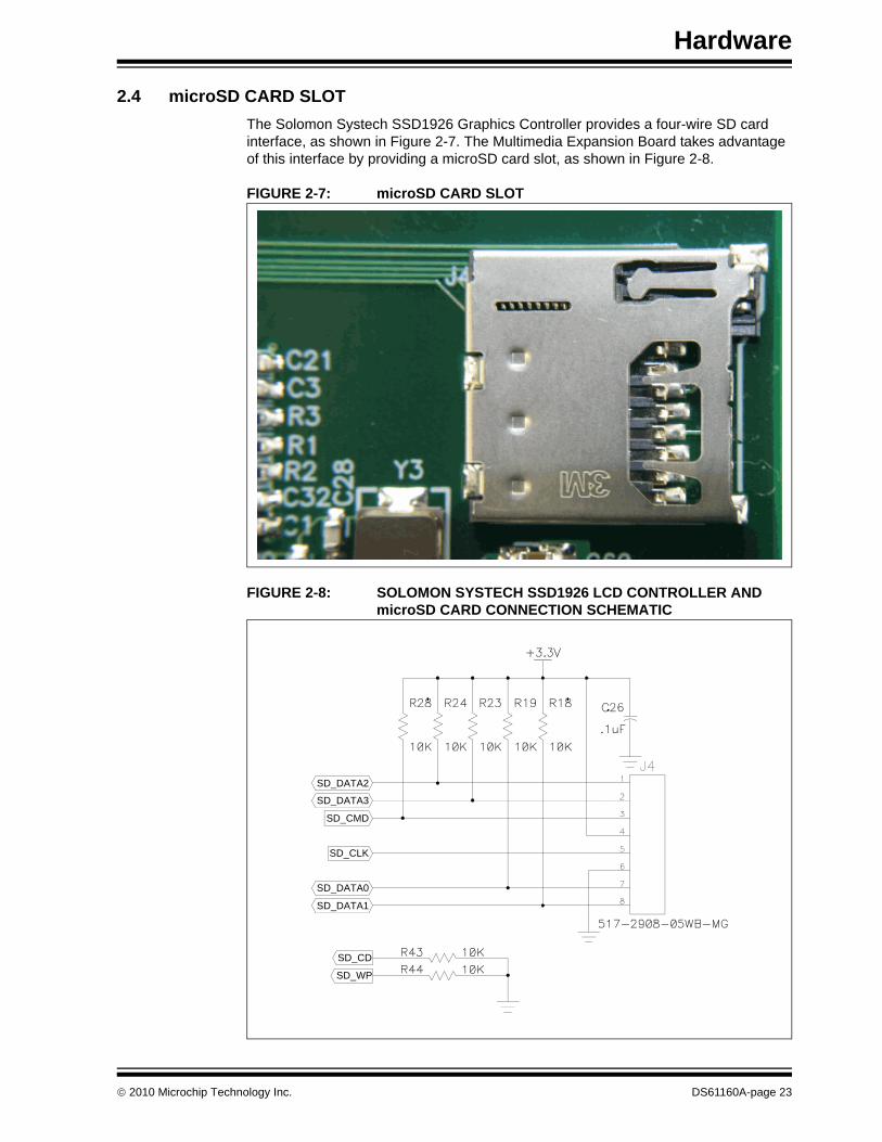
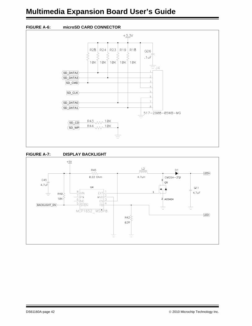
2.4 microSD CARD SLOTThe Solomon Systech SSD1926 Graphics Controller provides a four-wire SD card interface, as shown in Figure 2-7. The Multimedia Expansion Board takes advantage of this interface by providing a microSD card slot, as shown in Figure 2-8.
FIGURE 2-7: microSD CARD SLOT
FIGURE 2-8: SOLOMON SYSTECH SSD1926 LCD CONTROLLER AND microSD CARD CONNECTION SCHEMATIC
SD_WP
SD_DATA0
SD_CMD
SD_DATA2
SD_CD
SD_DATA1
SD_CLK
SD_DATA3
© 2010 Microchip Technology Inc. DS61160A-page 23
Multimedia Expansion Board User’s Guide
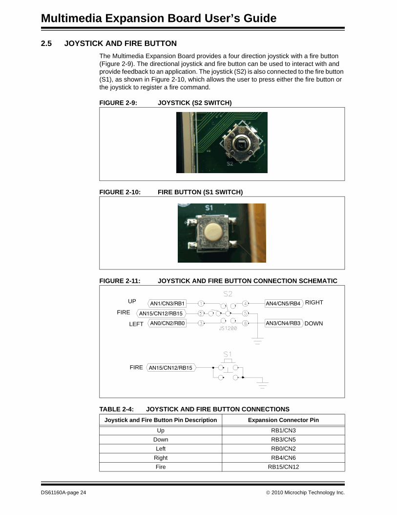
2.5 JOYSTICK AND FIRE BUTTONThe Multimedia Expansion Board provides a four direction joystick with a fire button (Figure 2-9). The directional joystick and fire button can be used to interact with and provide feedback to an application. The joystick (S2) is also connected to the fire button (S1), as shown in Figure 2-10, which allows the user to press either the fire button or the joystick to register a fire command.
FIGURE 2-9: JOYSTICK (S2 SWITCH)
FIGURE 2-10: FIRE BUTTON (S1 SWITCH)
FIGURE 2-11: JOYSTICK AND FIRE BUTTON CONNECTION SCHEMATIC
TABLE 2-4: JOYSTICK AND FIRE BUTTON CONNECTIONSJoystick and Fire Button Pin Description Expansion Connector Pin
Up RB1/CN3Down RB3/CN5Left RB0/CN2
Right RB4/CN6Fire RB15/CN12
AN1/CN3/RB1 AN4/CN5/RB4
AN0/CN2/RB0 AN3/CN4/RB3
AN15/CN12/RB15
AN15/CN12/RB15
UP
FIRE
LEFT
FIRE
RIGHT
DOWN
DS61160A-page 24 © 2010 Microchip Technology Inc.
Hardware
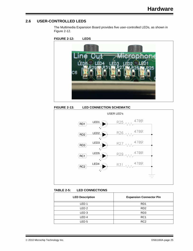
2.6 USER-CONTROLLED LEDSThe Multimedia Expansion Board provides five user-controlled LEDs, as shown in Figure 2-12.
FIGURE 2-12: LEDS
FIGURE 2-13: LED CONNECTION SCHEMATIC
TABLE 2-5: LED CONNECTIONS
LED Description Expansion Connector Pin
LED 1 RD1LED 2 RD2LED 3 RD3LED 4 RC1LED 5 RC2
RC2
RD3
RD2
RC1
RD1
USER LED’s
LED1
LED2
LED3
LED5
LED4
© 2010 Microchip Technology Inc. DS61160A-page 25
Multimedia Expansion Board User’s Guide
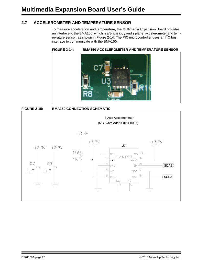
2.7 ACCELEROMETER AND TEMPERATURE SENSORTo measure acceleration and temperature, the Multimedia Expansion Board provides an interface to the BMA150, which is a 3-axis (x, y and z plane) accelerometer and tem-perature sensor, as shown in Figure 2-14. The PIC microcontroller uses an I2C bus interface to communicate with the BMA150.
FIGURE 2-14: BMA150 ACCELEROMETER AND TEMPERATURE SENSOR
FIGURE 2-15: BMA150 CONNECTION SCHEMATIC
SDA2
SCL2
U3
3 Axis Accelerometer
(I2C Slave Addr = 0111 000X)
DS61160A-page 26 © 2010 Microchip Technology Inc.
Hardware
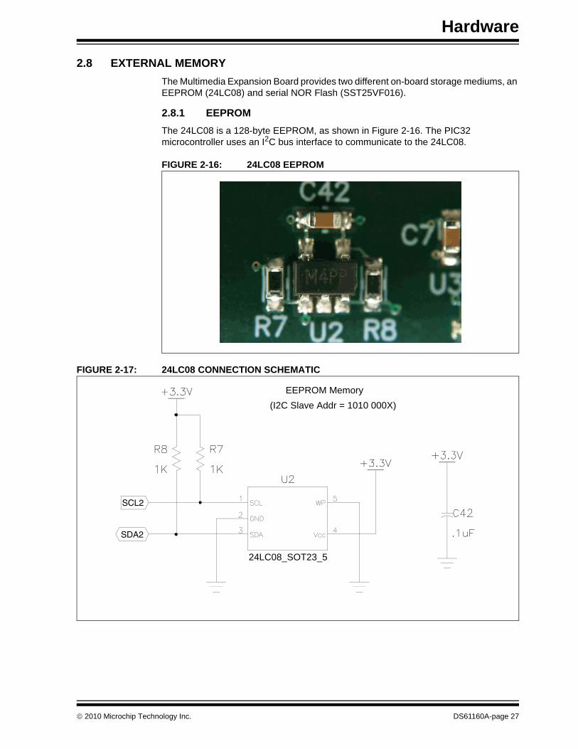
2.8 EXTERNAL MEMORYThe Multimedia Expansion Board provides two different on-board storage mediums, an EEPROM (24LC08) and serial NOR Flash (SST25VF016).
2.8.1 EEPROMThe 24LC08 is a 128-byte EEPROM, as shown in Figure 2-16. The PIC32 microcontroller uses an I2C bus interface to communicate to the 24LC08.
FIGURE 2-16: 24LC08 EEPROM
FIGURE 2-17: 24LC08 CONNECTION SCHEMATIC
SDA2
SCL2
EEPROM Memory (I2C Slave Addr = 1010 000X)
24LC08_SOT23_5
© 2010 Microchip Technology Inc. DS61160A-page 27
Multimedia Expansion Board User’s Guide
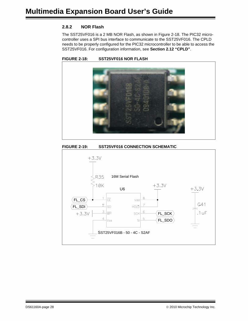
2.8.2 NOR FlashThe SST25VF016 is a 2 MB NOR Flash, as shown in Figure 2-18. The PIC32 micro-controller uses a SPI bus interface to communicate to the SST25VF016. The CPLD needs to be properly configured for the PIC32 microcontroller to be able to access the SST25VF016. For configuration information, see Section 2.12 “CPLD”.
FIGURE 2-18: SST25VF016 NOR FLASH
FIGURE 2-19: SST25VF016 CONNECTION SCHEMATIC
FL_SDI
FL_SCK
FL_CS
FL_SDO
16M Serial Flash
U6
SST25VF016B - 50 - 4C - S2AF
DS61160A-page 28 © 2010 Microchip Technology Inc.
Hardware
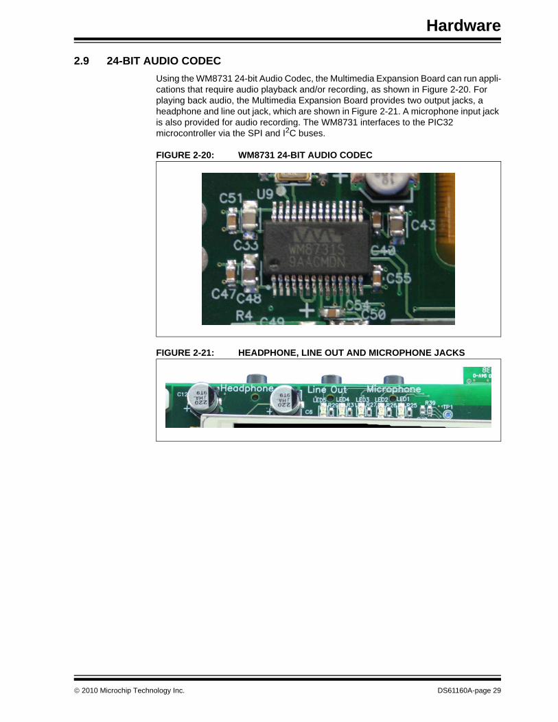
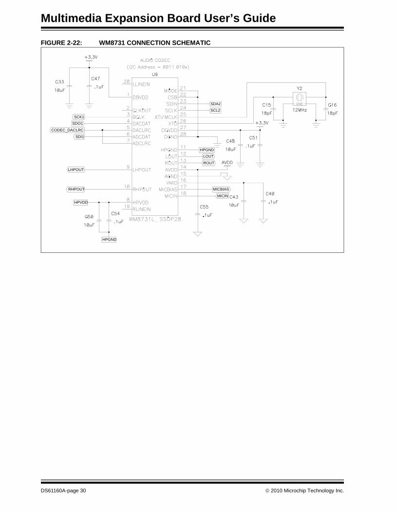
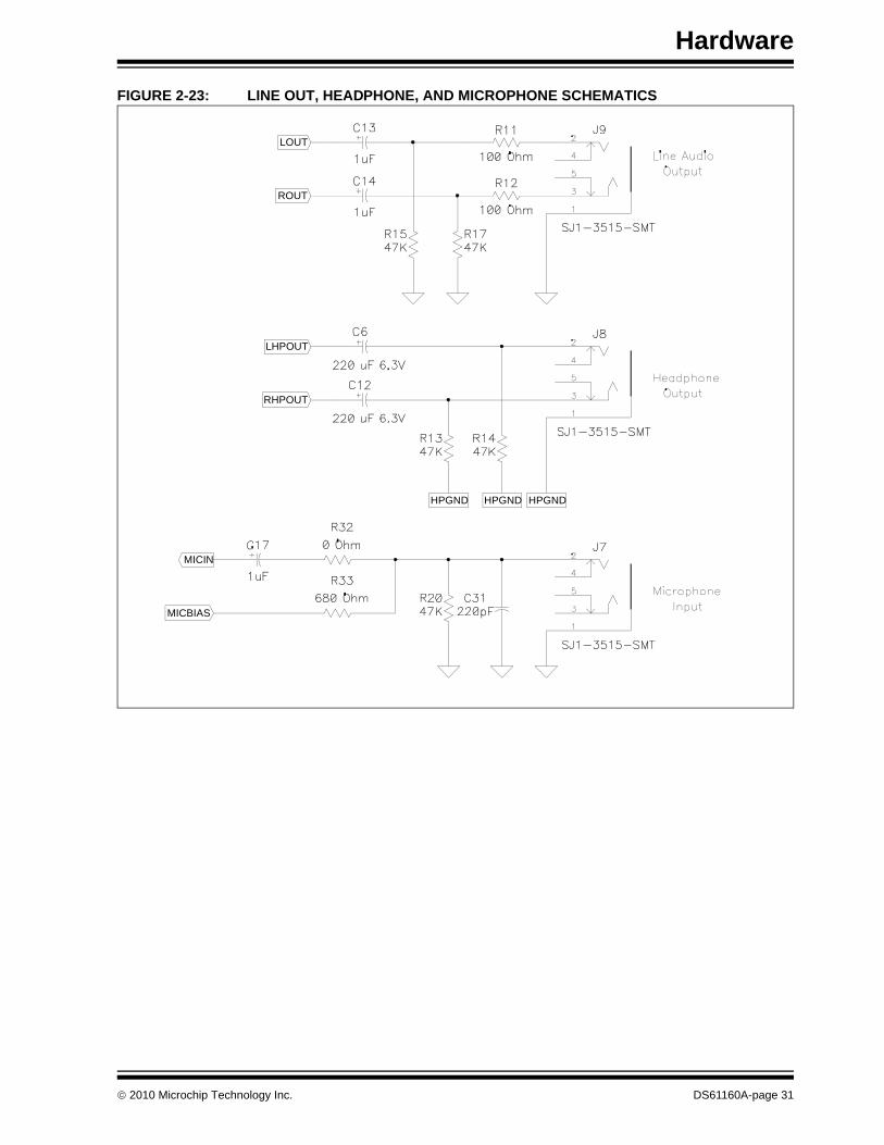
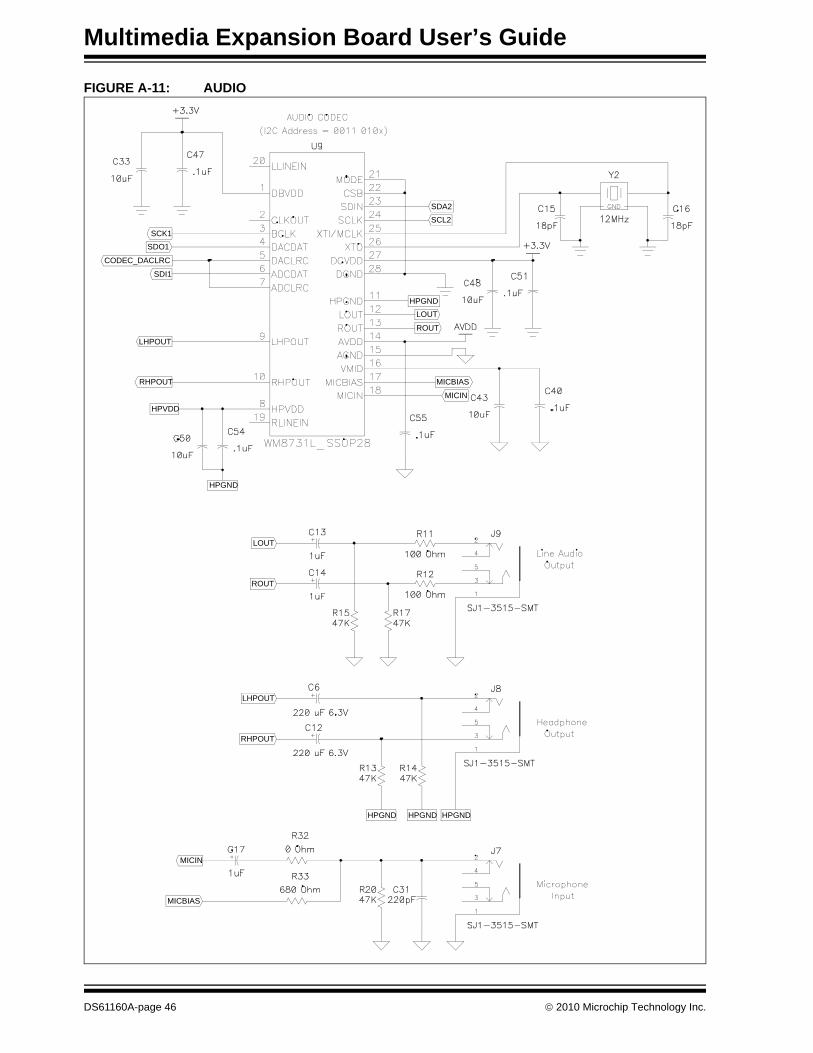
2.9 24-BIT AUDIO CODECUsing the WM8731 24-bit Audio Codec, the Multimedia Expansion Board can run appli-cations that require audio playback and/or recording, as shown in Figure 2-20. For playing back audio, the Multimedia Expansion Board provides two output jacks, a headphone and line out jack, which are shown in Figure 2-21. A microphone input jack is also provided for audio recording. The WM8731 interfaces to the PIC32 microcontroller via the SPI and I2C buses.
FIGURE 2-20: WM8731 24-BIT AUDIO CODEC
FIGURE 2-21: HEADPHONE, LINE OUT AND MICROPHONE JACKS
© 2010 Microchip Technology Inc. DS61160A-page 29
Multimedia Expansion Board User’s Guide
FIGURE 2-22: WM8731 CONNECTION SCHEMATIC
RHPOUT
LHPOUT
SDI1
SCK1
LOUTHPGND
SCL2
HPVDD
SDO1
ROUT
SDA2
MICIN
MICBIAS
HPGND
CODEC_DACLRC
DS61160A-page 30 © 2010 Microchip Technology Inc.
Hardware
FIGURE 2-23: LINE OUT, HEADPHONE, AND MICROPHONE SCHEMATICS
MICBIAS
MICIN
RHPOUT
LHPOUT
ROUT
LOUT
HPGND HPGNDHPGND
© 2010 Microchip Technology Inc. DS61160A-page 31
Multimedia Expansion Board User’s Guide
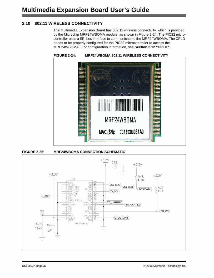
2.10 802.11 WIRELESS CONNECTIVITYThe Multimedia Expansion Board has 802.11 wireless connectivity, which is provided by the Microchip MRF24WBOMA module, as shown in Figure 2-24. The PIC32 micro-controller uses a SPI bus interface to communicate to the MRF24WBOMA. The CPLD needs to be properly configured for the PIC32 microcontroller to access the MRF24WBOMA. For configuration information, see Section 2.12 “CPLD”.
FIGURE 2-24: MRF24WBOMA 802.11 WIRELESS CONNECTIVITY
FIGURE 2-25: MRF24WBOMA CONNECTION SCHEMATIC
RA10
C1OUT/AN8
ZG_SCK
ZG_CS
ZG_UARTTXZG_UARTRX
ZG_SDIINT3/RA14
ZG_SDO
DS61160A-page 32 © 2010 Microchip Technology Inc.
Hardware
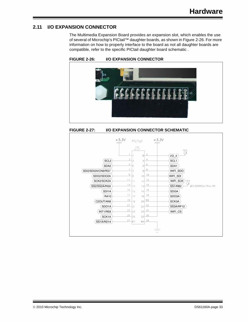
2.11 I/O EXPANSION CONNECTORThe Multimedia Expansion Board provides an expansion slot, which enables the use of several of Microchip’s PICtail™ daughter boards, as shown in Figure 2-26. For more information on how to properly interface to the board as not all daughter boards are compatible, refer to the specific PICtail daughter board schematic .
FIGURE 2-26: I/O EXPANSION CONNECTOR
FIGURE 2-27: I/O EXPANSION CONNECTOR SCHEMATIC
RA10
SCL2
WIFI_CS
SS3A/RF12
SDO3A
SDI3A
WIFI_SCK
WIFI_SDI
SDA1
SCL1
SCK3A
WIFI_SDO
SS1/RB2
I/O_4
SS1A/RD14
INT1/RE8
SDO1A
SDI1A
SCK2/SCK2A
SDO2/SDO2A
SDA2
C2OUT/AN9
SCK1A
SS2/SS2A/RG9
SDI2/SDI2A/CN9/RG7
© 2010 Microchip Technology Inc. DS61160A-page 33
Multimedia Expansion Board User’s Guide
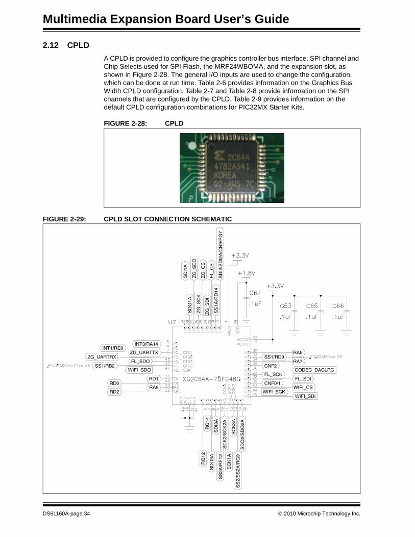
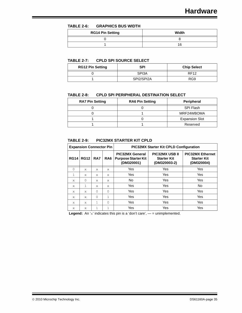
2.12 CPLDA CPLD is provided to configure the graphics controller bus interface, SPI channel and Chip Selects used for SPI Flash, the MRF24WBOMA, and the expansion slot, as shown in Figure 2-28. The general I/O inputs are used to change the configuration, which can be done at run time. Table 2-6 provides information on the Graphics Bus Width CPLD configuration. Table 2-7 and Table 2-8 provide information on the SPI channels that are configured by the CPLD. Table 2-9 provides information on the default CPLD configuration combinations for PIC32MX Starter Kits.
FIGURE 2-28: CPLD
FIGURE 2-29: CPLD SLOT CONNECTION SCHEMATIC
SD
I1A
RG
12Z
G_C
S
FL_
CS
SD
O1A
ZG
_SC
K
SD
I3A
SD
O3A
SS
1A/R
D14
SC
K2/
SC
K2A
SC
K1A
SD
O2/
SD
O2A
SS
2/S
S2A
/RG
9
SS1/RB2
RA9
RD1
FL_SDO
ZG_UARTTX
WIFI_CS
FL_SDI
RA7
RA6ZG_UARTRX
WIFI_SDO
INT3/RA14
WIFI_SDI
RG
14
SS
3A/R
F12
ZG
_SD
I
ZG
_SD
O
SD
I2/S
DI2
A/C
N9/
RG
7
SC
K3A
RD2
INT1/RE8
WIFI_SCK
FL_SCK
CNF2
RD0 CNF0/1
CODEC_DACLRC
SS1/RD9
DS61160A-page 34 © 2010 Microchip Technology Inc.
Hardware
TABLE 2-6: GRAPHICS BUS WIDTH
TABLE 2-7: CPLD SPI SOURCE SELECT
TABLE 2-8: CPLD SPI PERIPHERAL DESTINATION SELECT
TABLE 2-9: PIC32MX STARTER KIT CPLD
RG14 Pin Setting Width
0 81 16
RG12 Pin Setting SPI Chip Select
0 SPI3A RF121 SPI2/SPI2A RG9
RA7 Pin Setting RA6 Pin Setting Peripheral
0 0 SPI Flash0 1 MRF24WBOMA1 0 Expansion Slot1 1 Reserved
Expansion Connector Pin PIC32MX Starter Kit CPLD Configuration
RG14 RG12 RA7 RA6PIC32MX General
Purpose Starter Kit (DM320001)
PIC32MX USB II Starter Kit
(DM320003-2)
PIC32MX Ethernet Starter Kit
(DM320004)
0 x x x Yes Yes Yes1 x x x Yes Yes Yesx 0 x x No Yes Yesx 1 x x Yes Yes Nox x 0 0 Yes Yes Yesx x 0 1 Yes Yes Yesx x 1 0 Yes Yes Yesx x 1 1 Yes Yes Yes
Legend: An ‘x’ indicates this pin is a ‘don’t care’, — = unimplemented.
© 2010 Microchip Technology Inc. DS61160A-page 35

Multimedia Expansion Board User’s Guide
NOTES:
DS61160A-page 36 © 2010 Microchip Technology Inc.
MULTIMEDIA EXPANSIONBOARD USER’S GUIDE
Appendix A. Board Layout and Schematics
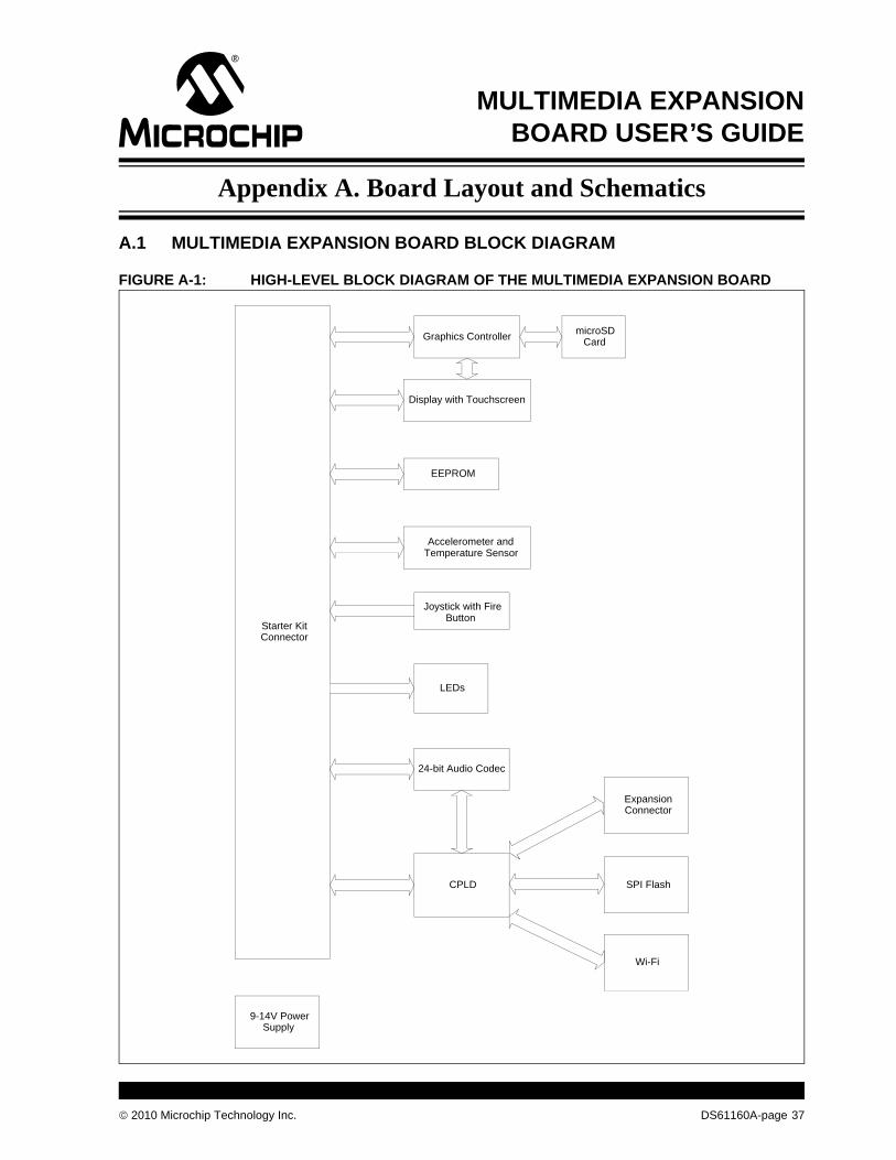
A.1 MULTIMEDIA EXPANSION BOARD BLOCK DIAGRAM
FIGURE A-1: HIGH-LEVEL BLOCK DIAGRAM OF THE MULTIMEDIA EXPANSION BOARD
Starter Kit Connector
Graphics Controller
Accelerometer and Temperature Sensor
microSD Card
EEPROM
SPI FlashCPLD
Wi-Fi
Expansion Connector
Display with Touchscreen
Joystick with Fire Button
24-bit Audio Codec
LEDs
9-14V Power Supply
© 2010 Microchip Technology Inc. DS61160A-page 37
© 2010 M
icrochip Technology Inc.D
S61160A
-page 38
A.
FIG
ediasion Board
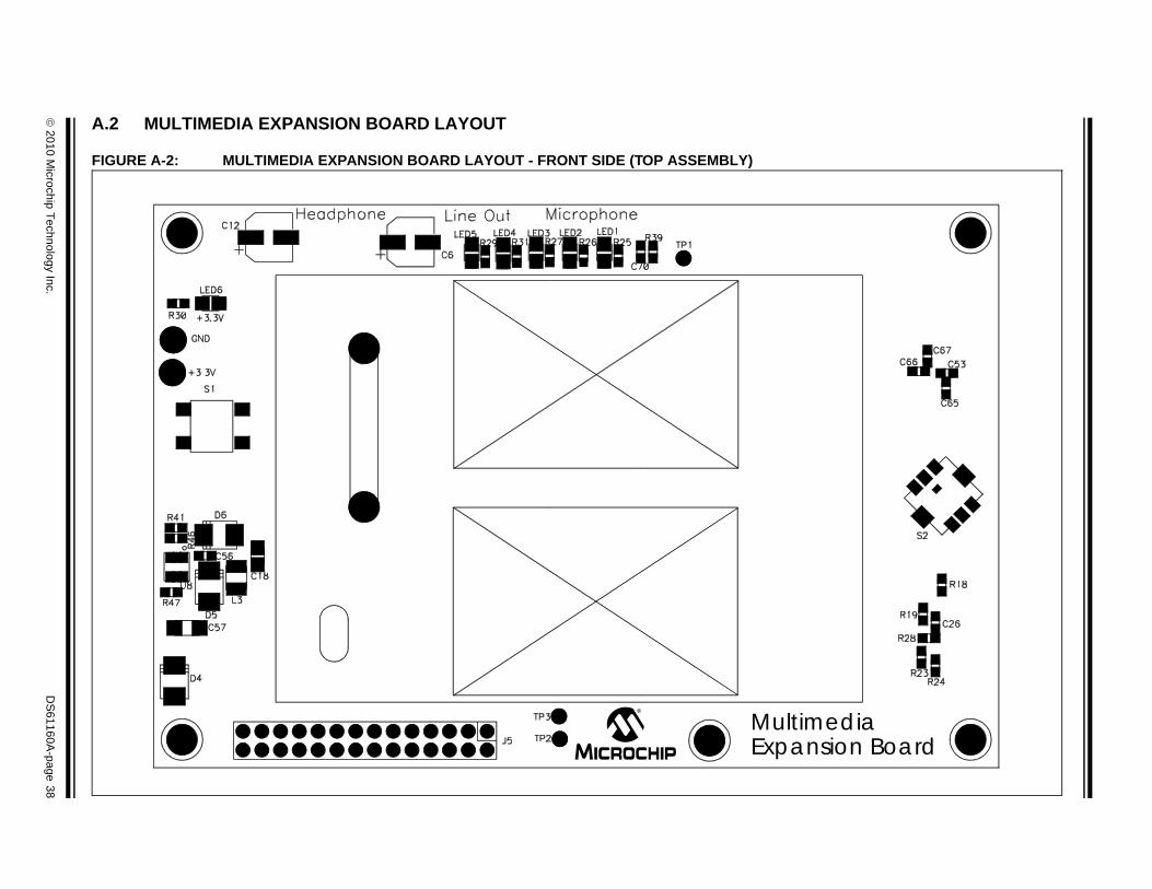
2 MULTIMEDIA EXPANSION BOARD LAYOUT
URE A-2: MULTIMEDIA EXPANSION BOARD LAYOUT - FRONT SIDE (TOP ASSEMBLY)
MultimExpan
© 2010 M
icrochip Technology Inc.D
S61160A
-page 39
FIG
URE A-3: MULTIMEDIA EXPANSION BOARD LAYOUT - BACK SIDE (TOP ASSEMBLY)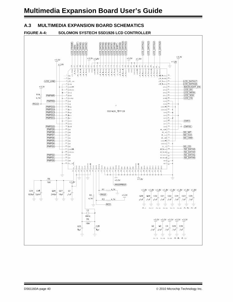
Multimedia Expansion Board User’s Guide
A.3 MULTIMEDIA EXPANSION BOARD SCHEMATICSFIGURE A-4: SOLOMON SYSTECH SSD1926 LCD CONTROLLER
LCD
_FR
AM
E
LCD
_RE
SE
TLC
D_D
ATA
0
LCD
_DA
TA2
LCD
_DA
TA4
LCD
_DA
TA5
LCD
_DA
TA7
LCD
_DA
TA8
LCD
_DA
TA9
LCD
_DA
TA10
LCD
_DA
TA13
LCD
_DA
TA14
RG13
PMPD1PMPD2
PMPD3
PMPD5PMPD6
PMPD8PMPD9
RC3
PMPD0
PMPD4
PMPD7
PMPRD
RA10
LCD
_DE
N
LCD
_DA
TA1
LCD
_DA
TA3
LCD
_DA
TA6
LCD
_SH
IFT
LCD
_DA
TA11
LCD
_DA
TA12
LCD
_DA
TA15
PMPD12PMPD13
PMPD15
PMPWR
LCD_LINE
AN10/RB10
SD_DATA0SD_DATA1
SD_DATA3SD_CD
SD_CMD
SD_WP
CNF2
LCD_CSLCD_SCK
LCD_DCBACKLIGHT_EN
LCD_DATA17
PMPD10
PMPD11
PMPD14
SD_DATA2
SD_CLK
CNF0/1
LCD_MOSI
LCD_DATA16
DS61160A-page 40 © 2010 Microchip Technology Inc.
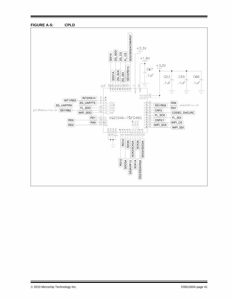
FIGURE A-5: CPLD
SD
I1A
RG
12Z
G_C
S
FL_
CS
SD
O1A
ZG
_SC
K
SD
I3A
SD
O3A
SS
1A/R
D14
SC
K2/
SC
K2A
SC
K1A
SD
O2/
SD
O2A
SS
2/S
S2A
/RG
9
SS1/RB2
RA9
RD1
FL_SDO
ZG_UARTTX
WIFI_CS
FL_SDI
RA7
RA6ZG_UARTRX
WIFI_SDO
INT3/RA14
WIFI_SDI
RG
14
SS
3A/R
F12
ZG
_SD
I
ZG
_SD
O
SD
I2/S
DI2
A/C
N9/
RG
7
SC
K3A
RD2
INT1/RE8
WIFI_SCK
FL_SCK
CNF2
RD0 CNF0/1
CODEC_DACLRC
SS1/RD9
© 2010 Microchip Technology Inc. DS61160A-page 41
Multimedia Expansion Board User’s Guide
FIGURE A-6: microSD CARD CONNECTOR
FIGURE A-7: DISPLAY BACKLIGHT
SD_WP
SD_DATA0
SD_CMD
SD_DATA2
SD_CD
SD_DATA1
SD_CLK
SD_DATA3
BACKLIGHT_EN
LED-
LED+
U4
2
3
1
Q5
AO3424
DS61160A-page 42 © 2010 Microchip Technology Inc.
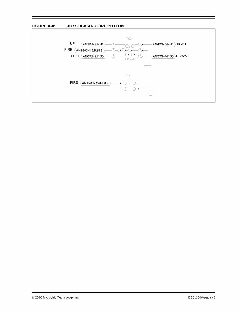
FIGURE A-8: JOYSTICK AND FIRE BUTTON
AN1/CN3/RB1 AN4/CN5/RB4
AN0/CN2/RB0 AN3/CN4/RB3
AN15/CN12/RB15
AN15/CN12/RB15
UP
FIRE
LEFT
RIGHT
DOWN
FIRE
© 2010 Microchip Technology Inc. DS61160A-page 43
Multimedia Expansion Board User’s Guide
FIGURE A-9: TOUCHSCREEN SOCKETS
LCD_SCK
LCD_MOSI
LCD_DC
LCD_DATA6
LCD_DATA7
LCD_DATA15
LCD_DATA16
LCD_DATA14
LCD_DATA13
LCD_DATA5
LCD_DATA4
LCD_DATA11
LCD_DATA10
LCD_DATA2
LCD_DATA1
LCD_DEN
LCD_SHIFT
LCD_FRAME
LCD_RESET
LED-
LED+
LCD_CS
LCD_DATA8
LCD_DATA17
LCD_DATA12
LCD_DATA3
LCD_DATA9
LCD_DATA0
LCD_LINE
AN13/RB13
AN12/RB12
AN14/RB14
AN11/RB11
DS61160A-page 44 © 2010 Microchip Technology Inc.
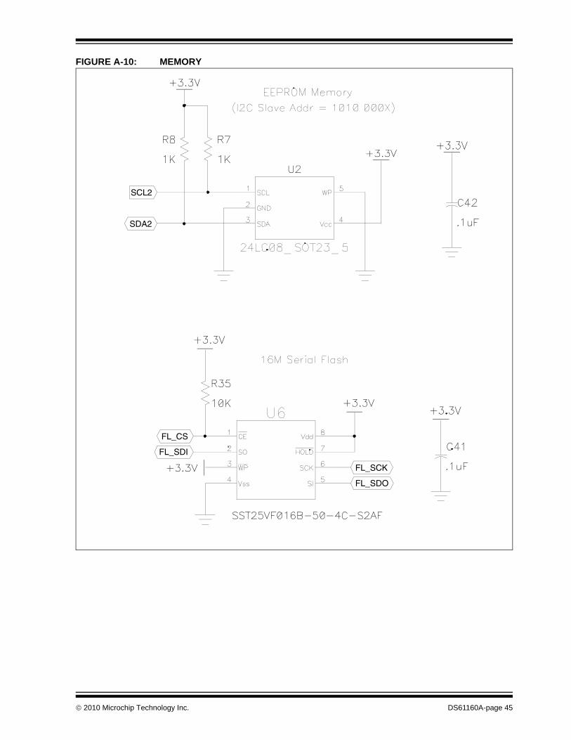
FIGURE A-10: MEMORY
SDA2
FL_SDI
FL_SCK
SCL2
FL_CS
FL_SDO
© 2010 Microchip Technology Inc. DS61160A-page 45
Multimedia Expansion Board User’s Guide
FIGURE A-11: AUDIO
RHPOUT
LHPOUT
SDI1
SCK1
LOUTHPGND
SCL2
MICBIAS
MICIN
RHPOUT
LHPOUT
ROUT
LOUT
HPVDD
SDO1
ROUT
SDA2
HPGND HPGND
MICIN
MICBIAS
HPGND
HPGND
CODEC_DACLRC
DS61160A-page 46 © 2010 Microchip Technology Inc.
© 2010 M
icrochip Technology Inc.D
S61160A
-page 47
FIG
URE A-12: POWER SUPPLY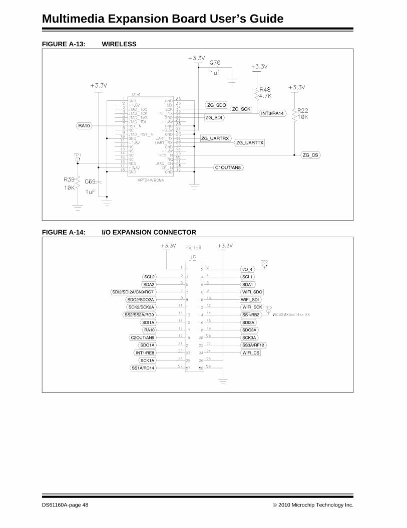
Multimedia Expansion Board User’s Guide
FIGURE A-13: WIRELESS
FIGURE A-14: I/O EXPANSION CONNECTOR
RA10
C1OUT/AN8
ZG_SCK
ZG_CS
ZG_UARTTXZG_UARTRX
ZG_SDIINT3/RA14
ZG_SDO
RA10
SCL2
WIFI_CS
SS3A/RF12
SDO3A
SDI3A
WIFI_SCK
WIFI_SDI
SDA1
SCL1
SCK3A
WIFI_SDO
SS1/RB2
I/O_4
SS1A/RD14
INT1/RE8
SDO1A
SDI1A
SCK2/SCK2A
SDO2/SDO2A
SDA2
C2OUT/AN9
SCK1A
SS2/SS2A/RG9
SDI2/SDI2A/CN9/RG7
DS61160A-page 48 © 2010 Microchip Technology Inc.
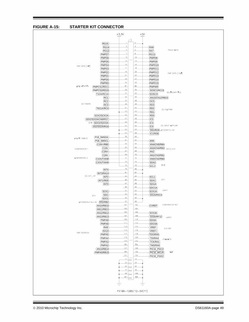
FIGURE A-15: STARTER KIT CONNECTOR
PMPA0/RB15
PMPA2PMPA3
PMPA5RA10
PMPA8PMPA9
AN12/RB12AN11/RB11
SS1/RB2SDO1
SCK1
INT1/RE8INT2
INT4
C1OUT/AN8C2IN-
C1IN-C1IN+/RB5
P18_SMSDA
SS2/SS2A/RG9SDO2/SDO2A
SCK2/SCK2A
RC3RC2
T1CK/RC14PMPCS2/RD10
PMPRDPMPD0
PMPD2PMPD3
PMPD5PMPD6
RG12RG14
PIC32_PGD2PIC32_MCLR
TMS/RA0TCK/RA1
TDO/RA5VREF+
SDO3ASDI3A
SCK3A
SCK1ASDO1A
SDA1SCL1
SCL2
AN0/CN2/RB0AN1/CN3/RB1
AN3/CN4/RB3AN4/CN5/RB4
IC1/RD8
IC3IC4
RD0RD1
RD3OC5
SOSCOSOSC1/RC13
PMPD15PMPD14
PMPD12PMPD11
PMPD9PMPD8
RA7RA6
PMPA4
AN14/RB14
AN13/RB13
RA9
SDI1
AN10/RB10
INT0
INT3/RA14
C2OUT/AN9
C2IN+
P18_SMSCL
T5CLK/RC4
SDI2/SDI2A/CN9/RG7
PMPCS1/RD11
RC1
PMPD4
PMPD1
RG15
PMPD7
TDI/RA4
PIC32_PGC2
VREF-
SS3A/RF12
CVREF
SS1A/RD14
SDI1A
SDA2
AN2
AN5
SS1/RD9
IC5
RD2
PMPWR
AN15/CN12/RB15
PMPD10
PMPD13
RG13
© 2010 Microchip Technology Inc. DS61160A-page 49
Multimedia Expansion Board User’s Guide
FIGURE A-16: ANALOG PLANES
FIGURE A-17: DIGITAL PLANES
HPGND
HPVDD
DS61160A-page 50 © 2010 Microchip Technology Inc.
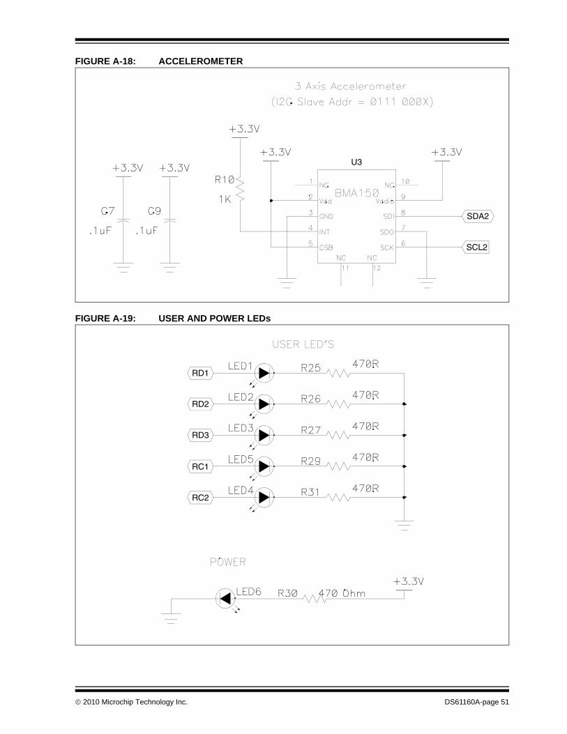
FIGURE A-18: ACCELEROMETER
FIGURE A-19: USER AND POWER LEDs
SDA2
SCL2
U3
RC2
RD3
RD2
RC1
RD1
© 2010 Microchip Technology Inc. DS61160A-page 51
Multimedia Expansion Board User’s Guide
NOTES:
DS61160A-page 52 © 2010 Microchip Technology Inc.
MULTIMEDIA EXPANSIONBOARD USER’S GUIDE
Appendix B. Bill of Materials (BOM)
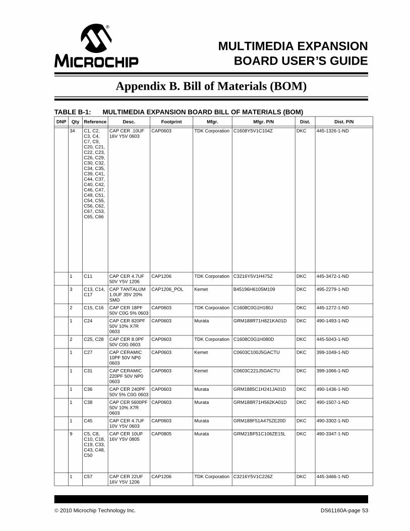
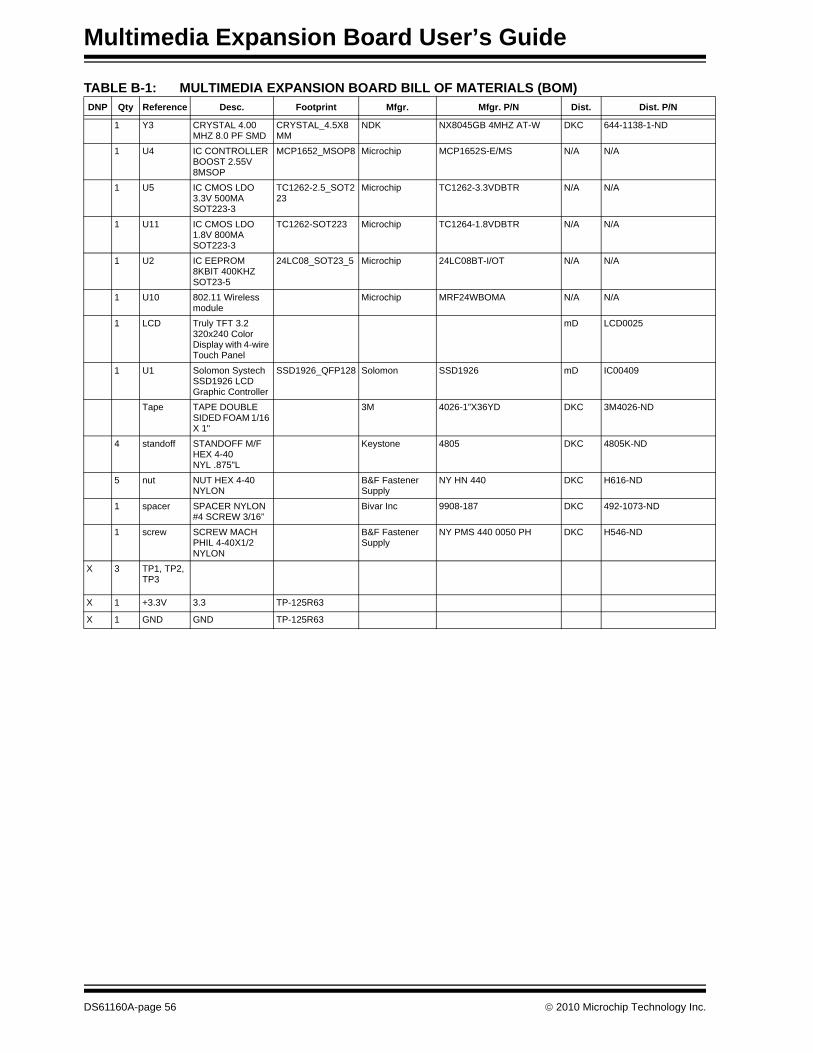
TABLE B-1: MULTIMEDIA EXPANSION BOARD BILL OF MATERIALS (BOM)DNP Qty Reference Desc. Footprint Mfgr. Mfgr. P/N Dist. Dist. P/N
34 C1, C2, C3, C4, C7, C9, C20, C21, C22, C23, C26, C29, C30, C32, C34, C35, C39, C41, C44, C37, C40, C42, C46, C47, C49, C51, C54, C55, C56, C62, C67, C53, C65, C66
CAP CER .10UF 16V Y5V 0603
CAP0603 TDK Corporation C1608Y5V1C104Z DKC 445-1326-1-ND
1 C11 CAP CER 4.7UF 50V Y5V 1206
CAP1206 TDK Corporation C3216Y5V1H475Z DKC 445-3472-1-ND
3 C13, C14, C17
CAP TANTALUM 1.0UF 35V 20% SMD
CAP1206_POL Kemet B45196H6105M109 DKC 495-2279-1-ND
2 C15, C16 CAP CER 18PF 50V C0G 5% 0603
CAP0603 TDK Corporation C1608C0G1H180J DKC 445-1272-1-ND
1 C24 CAP CER 820PF 50V 10% X7R 0603
CAP0603 Murata GRM188R71H821KA01D DKC 490-1493-1-ND
2 C25, C28 CAP CER 8.0PF 50V C0G 0603
CAP0603 TDK Corporation C1608C0G1H080D DKC 445-5043-1-ND
1 C27 CAP CERAMIC 10PF 50V NP0 0603
CAP0603 Kemet C0603C100J5GACTU DKC 399-1049-1-ND
1 C31 CAP CERAMIC 220PF 50V NP0 0603
CAP0603 Kemet C0603C221J5GACTU DKC 399-1066-1-ND
1 C36 CAP CER 240PF 50V 5% C0G 0603
CAP0603 Murata GRM1885C1H241JA01D DKC 490-1436-1-ND
1 C38 CAP CER 5600PF 50V 10% X7R 0603
CAP0603 Murata GRM188R71H562KA01D DKC 490-1507-1-ND
1 C45 CAP CER 4.7UF 10V Y5V 0603
CAP0603 Murata GRM188F51A475ZE20D DKC 490-3302-1-ND
9 C5, C8, C10, C18, C19, C33, C43, C48, C50
CAP CER 10UF 16V Y5V 0805
CAP0805 Murata GRM21BF51C106ZE15L DKC 490-3347-1-ND
1 C57 CAP CER 22UF 16V Y5V 1206
CAP1206 TDK Corporation C3216Y5V1C226Z DKC 445-3466-1-ND
© 2010 Microchip Technology Inc. DS61160A-page 53
Multimedia Expansion Board User’s Guide
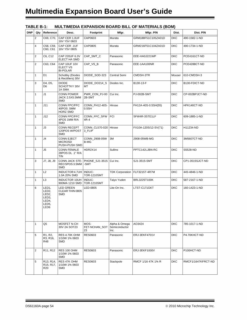
2 C69, C70, CAP CER 1.0UF 16V Y5V 0603
CAP0603 Murata GRM188F51C105ZA01D DKC 490-1582-1-ND
4 C58, C59, C60, C61
CAP CER .1UF 16V Y5V 0805
CAP0805 Murata GRM216F51C104ZA01D DKC 490-1734-1-ND
2 C6, C12 CAP 220UF 6.3V ELECT HA SMD
CAP_SMT_C Panasonic EEE-HA0J221WP DKC PCE4161CT-ND
2 C63, C64 CAP 10UF 10V ELECT VS BI-POLAR
CAP_VS_B Panasonic EEE-1AA100NR DKC PCE4288CT-ND
1 D1 Schottky (Diodes & Rectifiers) 30V
DIODE_SOD-323 Central Semi CMDSH-3TR Mouser 610-CMDSH-3
3 D4, D5, D6
DIODE SCHOTTKY 30V 1A SMA
DIODE_DO214_SMT
Diodes Inc. B130-13-F DKC B130-FDICT-ND
1 J1 CONN POWER JACK 2.5X5.5MM SMD
PWR_CON_PJ-002B-SMT
Cui Inc. PJ-002B-SMT DKC CP-002BPJCT-ND
1 J11 CONN FPC/FFC 40POS .5MM HORZ SMD
CONN_FH12-40S-0.5SH
Hirose FH12A-40S-0.5SH(55) DKC HFK140CT-ND
1 J12 CONN FPC/FFC 4POS 1MM R/A SMD
CONN_FFC_SFW4R-4
FCI SFW4R-3STE1LF DKC 609-1885-1-ND
1 J3 CONN RECEPT 120POS W/POST SMD
CONN_CL570-0203_FLIP
Hirose FX10A-120S/12-SV(71) DKC H11234-ND
1 J4 CONN EJECT MICROSD PUSH-PUSH SMD
CONN_2908-05WB-MG
3M 2908-05WB-MG DKC 3M5607CT-ND
1 J5 CONN FEMALE 28POS DL .1" R/A TIN
HDR2X14 Sullins PPTC142LJBN-RC DKC S5528-ND
3 J7, J8, J9 CONN JACK STE-REO 5POS 3.5MM SMD
PHONE_SJ1-3515-SMT
Cui Inc. SJ1-3515-SMT DKC CP1-3515SJCT-ND
1 L2 INDUCTOR 4.7UH 1.0A 20% SMD
INDUC-TOR-1210SMT
TDK Corporation FLF3215T-4R7M DKC 445-4846-1-ND
1 L3 INDUCTOR 10UH 900MA 1210 SMD
INDUC-TOR-1210SMT
Taiyo Yuden BRL3225T100K DKC 587-2167-1-ND
6 LED1, LED2, LED2, LED3, LED4, LED5, LED6
LED GREEN CLEAR THIN 0805 SMD
LED-0805 Lite-On Inc. LTST-C171GKT DKC 160-1423-1-ND
1 Q5 MOSFET N-CH 30V 2A SOT23
MOS-FET-NCHAN_SOT23
Alpha & Omega Semiconductor Inc.
AO3424 DKC 785-1017-1-ND
5 R1, R2, R3, R16, R48
RES 4.70K OHM 1/10W 1% 0603 SMD
RES0603 Panasonic ERJ-3EKF4701V DKC P4.70KHCT-ND
2 R11, R12 RES 100 OHM 1/10W 1% 0603 SMD
RES0603 Panasonic ERJ-3EKF1000V DKC P100HCT-ND
5 R13, R14, R15, R17, R20
RES 47K OHM 1/10W 1% 0603 SMD
RES0603 Stackpole RMCF 1/16 47K 1% R DKC RMCF1/1647KFRCT-ND
TABLE B-1: MULTIMEDIA EXPANSION BOARD BILL OF MATERIALS (BOM)DNP Qty Reference Desc. Footprint Mfgr. Mfgr. P/N Dist. Dist. P/N
DS61160A-page 54 © 2010 Microchip Technology Inc.
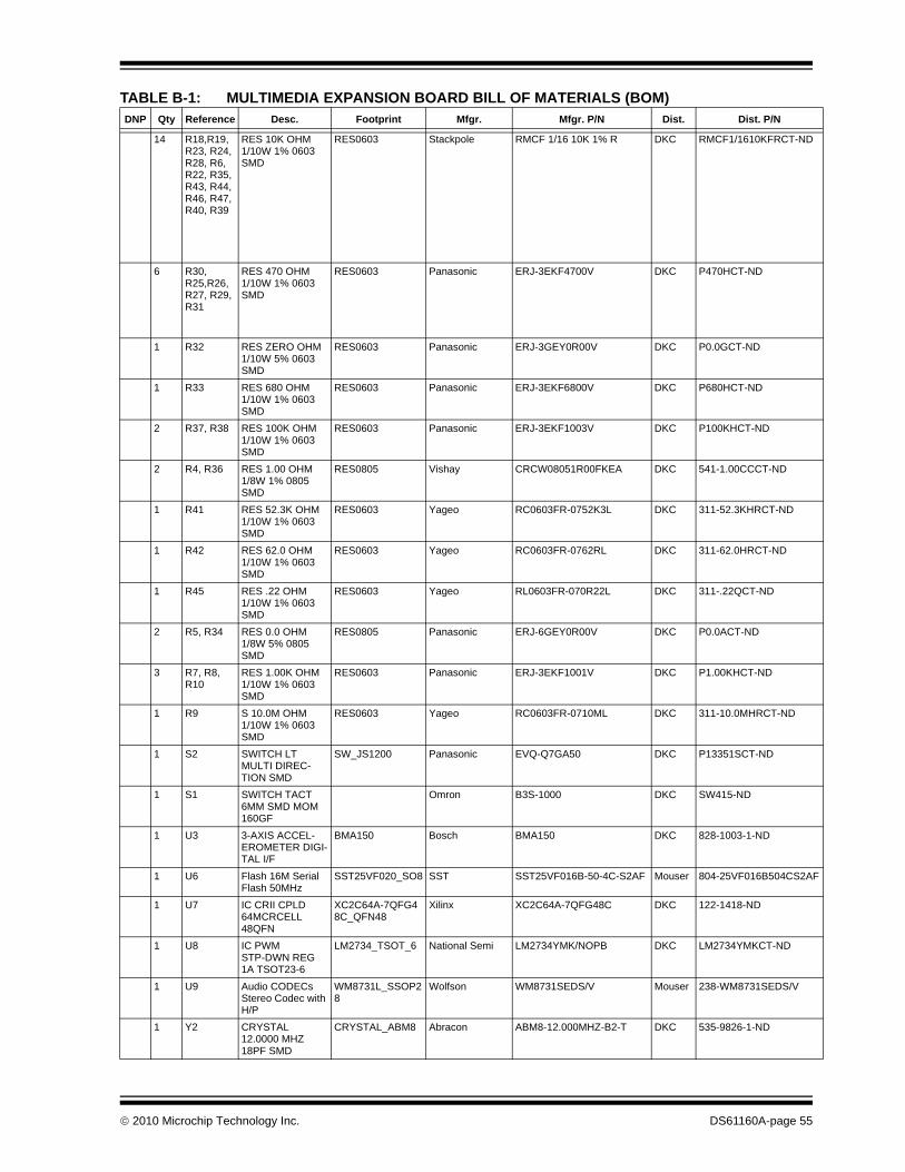
14 R18,R19, R23, R24, R28, R6, R22, R35, R43, R44, R46, R47, R40, R39
RES 10K OHM 1/10W 1% 0603 SMD
RES0603 Stackpole RMCF 1/16 10K 1% R DKC RMCF1/1610KFRCT-ND
6 R30, R25,R26, R27, R29, R31
RES 470 OHM 1/10W 1% 0603 SMD
RES0603 Panasonic ERJ-3EKF4700V DKC P470HCT-ND
1 R32 RES ZERO OHM 1/10W 5% 0603 SMD
RES0603 Panasonic ERJ-3GEY0R00V DKC P0.0GCT-ND
1 R33 RES 680 OHM 1/10W 1% 0603 SMD
RES0603 Panasonic ERJ-3EKF6800V DKC P680HCT-ND
2 R37, R38 RES 100K OHM 1/10W 1% 0603 SMD
RES0603 Panasonic ERJ-3EKF1003V DKC P100KHCT-ND
2 R4, R36 RES 1.00 OHM 1/8W 1% 0805 SMD
RES0805 Vishay CRCW08051R00FKEA DKC 541-1.00CCCT-ND
1 R41 RES 52.3K OHM 1/10W 1% 0603 SMD
RES0603 Yageo RC0603FR-0752K3L DKC 311-52.3KHRCT-ND
1 R42 RES 62.0 OHM 1/10W 1% 0603 SMD
RES0603 Yageo RC0603FR-0762RL DKC 311-62.0HRCT-ND
1 R45 RES .22 OHM 1/10W 1% 0603 SMD
RES0603 Yageo RL0603FR-070R22L DKC 311-.22QCT-ND
2 R5, R34 RES 0.0 OHM 1/8W 5% 0805 SMD
RES0805 Panasonic ERJ-6GEY0R00V DKC P0.0ACT-ND
3 R7, R8, R10
RES 1.00K OHM 1/10W 1% 0603 SMD
RES0603 Panasonic ERJ-3EKF1001V DKC P1.00KHCT-ND
1 R9 S 10.0M OHM 1/10W 1% 0603 SMD
RES0603 Yageo RC0603FR-0710ML DKC 311-10.0MHRCT-ND
1 S2 SWITCH LT MULTI DIREC-TION SMD
SW_JS1200 Panasonic EVQ-Q7GA50 DKC P13351SCT-ND
1 S1 SWITCH TACT 6MM SMD MOM 160GF
Omron B3S-1000 DKC SW415-ND
1 U3 3-AXIS ACCEL-EROMETER DIGI-TAL I/F
BMA150 Bosch BMA150 DKC 828-1003-1-ND
1 U6 Flash 16M Serial Flash 50MHz
SST25VF020_SO8 SST SST25VF016B-50-4C-S2AF Mouser 804-25VF016B504CS2AF
1 U7 IC CRII CPLD 64MCRCELL 48QFN
XC2C64A-7QFG48C_QFN48
Xilinx XC2C64A-7QFG48C DKC 122-1418-ND
1 U8 IC PWM STP-DWN REG 1A TSOT23-6
LM2734_TSOT_6 National Semi LM2734YMK/NOPB DKC LM2734YMKCT-ND
1 U9 Audio CODECs Stereo Codec with H/P
WM8731L_SSOP28
Wolfson WM8731SEDS/V Mouser 238-WM8731SEDS/V
1 Y2 CRYSTAL 12.0000 MHZ 18PF SMD
CRYSTAL_ABM8 Abracon ABM8-12.000MHZ-B2-T DKC 535-9826-1-ND
TABLE B-1: MULTIMEDIA EXPANSION BOARD BILL OF MATERIALS (BOM)DNP Qty Reference Desc. Footprint Mfgr. Mfgr. P/N Dist. Dist. P/N
© 2010 Microchip Technology Inc. DS61160A-page 55
Multimedia Expansion Board User’s Guide
1 Y3 CRYSTAL 4.00 MHZ 8.0 PF SMD
CRYSTAL_4.5X8MM
NDK NX8045GB 4MHZ AT-W DKC 644-1138-1-ND
1 U4 IC CONTROLLER BOOST 2.55V 8MSOP
MCP1652_MSOP8 Microchip MCP1652S-E/MS N/A N/A
1 U5 IC CMOS LDO 3.3V 500MA SOT223-3
TC1262-2.5_SOT223
Microchip TC1262-3.3VDBTR N/A N/A
1 U11 IC CMOS LDO 1.8V 800MA SOT223-3
TC1262-SOT223 Microchip TC1264-1.8VDBTR N/A N/A
1 U2 IC EEPROM 8KBIT 400KHZ SOT23-5
24LC08_SOT23_5 Microchip 24LC08BT-I/OT N/A N/A
1 U10 802.11 Wireless module
Microchip MRF24WBOMA N/A N/A
1 LCD Truly TFT 3.2 320x240 Color Display with 4-wire Touch Panel
mD LCD0025
1 U1 Solomon Systech SSD1926 LCD Graphic Controller
SSD1926_QFP128 Solomon SSD1926 mD IC00409
Tape TAPE DOUBLE SIDED FOAM 1/16 X 1"
3M 4026-1”X36YD DKC 3M4026-ND
4 standoff STANDOFF M/F HEX 4-40 NYL .875"L
Keystone 4805 DKC 4805K-ND
5 nut NUT HEX 4-40 NYLON
B&F Fastener Supply
NY HN 440 DKC H616-ND
1 spacer SPACER NYLON #4 SCREW 3/16”
Bivar Inc 9908-187 DKC 492-1073-ND
1 screw SCREW MACH PHIL 4-40X1/2 NYLON
B&F Fastener Supply
NY PMS 440 0050 PH DKC H546-ND
X 3 TP1, TP2, TP3
X 1 +3.3V 3.3 TP-125R63
X 1 GND GND TP-125R63
TABLE B-1: MULTIMEDIA EXPANSION BOARD BILL OF MATERIALS (BOM)DNP Qty Reference Desc. Footprint Mfgr. Mfgr. P/N Dist. Dist. P/N
DS61160A-page 56 © 2010 Microchip Technology Inc.
MULTIMEDIA EXPANSIONBOARD USER’S GUIDE
Index
BBill of Materials (BOM) ............................................. 53Block Diagrams
High-level .......................................................... 37Board Layout
Back side components...................................... 12Front side components ..................................... 11Top Assembly (Back of Board) ......................... 39Top Assembly (Front Side of Board)................. 38
CCustomer Change Notification Service ...................... 8Customer Support ...................................................... 8
DDocumentation
Conventions........................................................ 6
HHardware
Accelerometer and temperature sensor............ 26Audio codec ...................................................... 29CPLD ................................................................ 34External memory............................................... 27I/O Expansion Connector.................................. 33Joystick and Fire Button ................................... 24LCD controller ................................................... 19microSD card interface ..................................... 23PIC32 expansion connector.............................. 16Power supply .................................................... 15QVGA TFT touchscreen ................................... 19User-controlled LEDs........................................ 25Wireless connectivity ........................................ 32
IInternet Address......................................................... 7
MMicrochip Internet Web Site ....................................... 7MPLAB IDE Simulator, Editor User’s Guide............... 7Multimedia Expansion Board
Kit contents ....................................................... 11
RReadme ..................................................................... 7
SSchematics
Accelerometer................................................... 51Analog Planes................................................... 50Audio................................................................. 46CPLD ................................................................ 41Digital planes .................................................... 50
Display backlight ............................................... 42Joystick and fire button ..................................... 43Memory ............................................................. 45microSD card connector ................................... 42PICtail™ expansion connector.......................... 48Power supply .................................................... 47Solomon Systech SSD1926 LCD Controller..... 40Starter Kit connector ......................................... 49Touchscreen sockets ........................................ 44User and power LEDs....................................... 51Wireless ............................................................ 48
WWWW Address........................................................... 7
© 2010 Microchip Technology Inc. DS61160A-page 57
DS61160A-page 58 © 2010 Microchip Technology Inc.
AMERICASCorporate Office2355 West Chandler Blvd.Chandler, AZ 85224-6199Tel: 480-792-7200 Fax: 480-792-7277Technical Support: http://support.microchip.comWeb Address: www.microchip.comAtlantaDuluth, GA Tel: 678-957-9614 Fax: 678-957-1455BostonWestborough, MA Tel: 774-760-0087 Fax: 774-760-0088ChicagoItasca, IL Tel: 630-285-0071 Fax: 630-285-0075ClevelandIndependence, OH Tel: 216-447-0464 Fax: 216-447-0643DallasAddison, TX Tel: 972-818-7423 Fax: 972-818-2924DetroitFarmington Hills, MI Tel: 248-538-2250Fax: 248-538-2260KokomoKokomo, IN Tel: 765-864-8360Fax: 765-864-8387Los AngelesMission Viejo, CA Tel: 949-462-9523 Fax: 949-462-9608Santa ClaraSanta Clara, CA Tel: 408-961-6444Fax: 408-961-6445TorontoMississauga, Ontario, CanadaTel: 905-673-0699 Fax: 905-673-6509
ASIA/PACIFICAsia Pacific OfficeSuites 3707-14, 37th FloorTower 6, The GatewayHarbour City, KowloonHong KongTel: 852-2401-1200Fax: 852-2401-3431Australia - SydneyTel: 61-2-9868-6733Fax: 61-2-9868-6755China - BeijingTel: 86-10-8528-2100 Fax: 86-10-8528-2104China - ChengduTel: 86-28-8665-5511Fax: 86-28-8665-7889China - ChongqingTel: 86-23-8980-9588Fax: 86-23-8980-9500China - Hong Kong SARTel: 852-2401-1200 Fax: 852-2401-3431China - NanjingTel: 86-25-8473-2460Fax: 86-25-8473-2470China - QingdaoTel: 86-532-8502-7355Fax: 86-532-8502-7205China - ShanghaiTel: 86-21-5407-5533 Fax: 86-21-5407-5066China - ShenyangTel: 86-24-2334-2829Fax: 86-24-2334-2393China - ShenzhenTel: 86-755-8203-2660 Fax: 86-755-8203-1760China - WuhanTel: 86-27-5980-5300Fax: 86-27-5980-5118China - XianTel: 86-29-8833-7252Fax: 86-29-8833-7256China - XiamenTel: 86-592-2388138 Fax: 86-592-2388130China - ZhuhaiTel: 86-756-3210040 Fax: 86-756-3210049
ASIA/PACIFICIndia - BangaloreTel: 91-80-3090-4444 Fax: 91-80-3090-4123India - New DelhiTel: 91-11-4160-8631Fax: 91-11-4160-8632India - PuneTel: 91-20-2566-1512Fax: 91-20-2566-1513Japan - YokohamaTel: 81-45-471- 6166 Fax: 81-45-471-6122Korea - DaeguTel: 82-53-744-4301Fax: 82-53-744-4302Korea - SeoulTel: 82-2-554-7200Fax: 82-2-558-5932 or 82-2-558-5934Malaysia - Kuala LumpurTel: 60-3-6201-9857Fax: 60-3-6201-9859Malaysia - PenangTel: 60-4-227-8870Fax: 60-4-227-4068Philippines - ManilaTel: 63-2-634-9065Fax: 63-2-634-9069SingaporeTel: 65-6334-8870Fax: 65-6334-8850Taiwan - Hsin ChuTel: 886-3-6578-300Fax: 886-3-6578-370Taiwan - KaohsiungTel: 886-7-536-4818Fax: 886-7-536-4803Taiwan - TaipeiTel: 886-2-2500-6610 Fax: 886-2-2508-0102Thailand - BangkokTel: 66-2-694-1351Fax: 66-2-694-1350
EUROPEAustria - WelsTel: 43-7242-2244-39Fax: 43-7242-2244-393Denmark - CopenhagenTel: 45-4450-2828 Fax: 45-4485-2829France - ParisTel: 33-1-69-53-63-20 Fax: 33-1-69-30-90-79Germany - MunichTel: 49-89-627-144-0 Fax: 49-89-627-144-44Italy - Milan Tel: 39-0331-742611 Fax: 39-0331-466781Netherlands - DrunenTel: 31-416-690399 Fax: 31-416-690340Spain - MadridTel: 34-91-708-08-90Fax: 34-91-708-08-91UK - WokinghamTel: 44-118-921-5869Fax: 44-118-921-5820
Worldwide Sales and Service
01/05/10