Embed Size (px)
Citation preview

aettcra
mstai
Multilayer-coating-induced aberrations inextreme-ultraviolet lithography optics
Chen Liang, Michael R. Descour, Jose M. Sasian, and Scott A. Lerner
A multilayer coating alters the amplitude and phase of a reflected wave front. The amplitude effects aremultiplicative and well understood. We present a mathematical formalism that can be used to describethe phase effects of coating in a general case. On the basis of this formalism we have developed ananalytical method of estimating the wave-front aberrations introduced by the multilayer coating. Forthe case of field-independent aberrations, we studied both uniform and graded multilayer coatings. Forthe case of field-dependent aberrations, we studied only the effects of a uniform multilayer coating. Ouranalysis is based on a coated plane mirror tilted with respect to an incident converging beam. Altogetherwe have found, up to the second order, the following aberrations: a field-dependent piston, a field-squared-dependent piston, defocus, field-independent tilt, field-independent astigmatism, and anamor-phic magnification. To obtain numerical results we apply our analysis to the specific case of a planemirror tilted 8.2 deg with respect to an incident converging beam with a numerical aperture of 0.1. Wefind that the magnitudes of the field-independent aberration coefficients for the graded coating areapproximately ten times smaller than those for the uniform coating. We show that a coating canintroduce anamorphic magnification. © 2001 Optical Society of America
OCIS codes: 310.1620, 310.6860, 230.4170, 220.3740, 110.3960.
1. Introduction
A multilayer coating is designed to either enhance orsuppress reflection of radiation from a surface. Acoating that suppresses reflection is called an antire-flection coating. In the context of extreme-ultraviolet lithography ~EUVL!, multilayer coatingsre designed to have an opposite effect, that is, tonhance the surface reflectance to maximize the totalransmission of a multimirror system. In additiono changing the reflectance of a surface, a multilayeroating also introduces a phase shift to the reflectedadiation. This phase shift is related to aberrationsnd thus to image quality.The effects of multilayer coatings on the perfor-ance of an optical system have been studied by
everal authors. Reiley and Chipman have studiedhe effects of multilayer coatings on image quality forCassegrain telescope configuration using a numer-
cal method.1 In the context of EUVL projection
The authors are with the Optical Sciences Center, University ofArizona, Tucson, Arizona 85721-001. C. Liang’s e-mail address [email protected].
Received 21 January 2000; revised manuscript received 10 Au-gust 2000.
0003-6935y01y010129-07$15.00y0© 2001 Optical Society of America
cameras, the effects of multilayer coatings have beenmodeled in cases of specific camera designs by Jewell2and Duddles.3 Numerical values for the aberrationcoefficients that are due to coating were calculated byJewell using ray trace software Code V4; the effect onperformance of multilayer coating in an EUVL sys-tem analyzed by Duddles was also done using Code V.Watanabe et al. have studied the effect of coatingsdirectly on the point-spread function of an EUVLprojection camera.5 In this paper, to provide an an-alytical solution to accomplish similar tasks, wepresent an analytical method of estimating aberra-tions that are introduced by a multilayer coating.An analytical solution offers a better understandingon how aberrations are related to different parame-ters of the multilayer coating design. An exagger-ated parallel would be the Seidel coefficients in lensdesign. The limitation of this analytical method liesin the symbolic manipulations of mathematical ex-pressions related to complex multilayer and opticalgeometry.
The amplitude attenuation and the phase shift in-troduced by a multilayer coating depend on the localangle of incidence. To put the effects of a multilayercoating in the context of an optical system, we modelthe angle of incidence on a multilayer-coated surfaceas a function of pupil position and field position.Next we develop a second-order approximation to the
1 January 2001 y Vol. 40, No. 1 y APPLIED OPTICS 129

bmsotifb8fi
isosmit1p
vi
1
dependence of phase shift on angle of incidence for amultilayer coating design. Finally, the two resultsare combined to relate the phase shift introduced onreflection from a multilayer coating to the pupil andfield positions. In this fashion, we develop analyti-cal expressions for wave-front aberrations caused bya multilayer coating.
We begin our analysis with the field-independentaberrations case in which the field coordinate is set tozero. The required analysis is simpler and serves tointroduce our approach. A specific consequence ofthe zero field is a simple mathematical expression forthe angle of incidence. This simplicity is lost in thefield-dependent aberrations case, and the mathemat-ical expressions and derivations became much morecumbersome. For lithography systems the field-dependent case is more relevant, and this is alsodiscussed.
In this paper we analyze two kinds of multilayercoatings. A uniform coating has a uniform thick-ness across the entire optical surface, whereas agraded coating has a thickness that varies with re-spect to position on the optical surface. Figure 1shows the difference between the two coating types.At a given field position, uniform coating can be op-timized only for one specific angle of incidence. Onthe other hand, a graded coating can be optimized forall angles of incidence associated with a given fieldposition. As a result, a graded coating offers a sig-nificant advantage over a uniform coating at thesame field position. In our example calculations, theaberration coefficients introduced by the graded coat-ing are approximately ten times smaller than thoseintroduced by the uniform coating.
We begin by studying a multilayer-coated planemirror. A plane mirror represents a simple case inwhich it is easier to interpret the analytical and nu-merical results. A multilayer-coated plane mirrorcan also serve as a model of the photomask in a EUVLsystem to estimate the condenser aberrations intro-duced by the multilayer coating on the photomask.To obtain numerical results in the case of field-independent aberration, a specific optical system con-figuration is studied: a plane mirror tilted 8.2 degwith respect to a converging incident beam with anumerical aperture ~NA! of 0.1. This configurationis illustrated in Fig. 2~a!. In the case of field-dependent aberrations, we study a similar configura-
Fig. 1. Schematic comparison of a uniform coating versus agraded coating. Only one layer pair is drawn here and the dia-grams are not to scale.
30 APPLIED OPTICS y Vol. 40, No. 1 y 1 January 2001
tion. For the given value of NA, the mirror tilt angleand maximum field angle ~chief ray angle! are limitedy the reflectance of the multilayer coating and theirror geometry. The mirror tilt angle needs to be
mall to sustain a high reflectance, e.g., above 45%,ver a wide range of angles of incidence. However,he geometry of the optical system and the field anglempose a lower limit on the mirror tilt angle for theocal spot to clear the cone of the incident convergingeam. For this paper we chose a mirror tilt angle of.2 deg and a chief ray angle of 1.43 deg. This con-guration is illustrated in Fig. 2~b!.The example of the plane mirror tilt case analyzed
n this paper was selected to exclude considerations ofignificantly different polarization-dependent effectsn the reflection from the multilayer-coated sub-trate. At the tilt angle of 8.2°, the effect of theultilayer coating is still approximately the same for
ncident radiation of s and p polarizations. Even athe maximum angle of incidence there is less than a0% difference between the phase shift of the s and polarized light.
2. Modeling of Multilayer Coatings
The multilayer coating design for the uniform coatingand the optical constants of silicon ~Si!, molybdenum~Mo!, and silica ~SiO2! were obtained from the Centerfor X-Ray Optics website.6 The nominal coating de-sign consists of 40 Mo–Si layer pairs. Mo is theabsorber layer and Si is the spacer layer.7 The Molayer thickness ~da! is 2.8 nm, and the Si layer thick-ness ~ds! is 4.2 nm. This translates to a period ~L! of7 nm and a parameter G 5 dayL 5 0.4 in multilayercoating terms. The mirror substrate is SiO2. Forthe above materials the complex optical admittancesat the wavelength of 13.4 nm are
ySi 5 0.999934 2 j1.8211 3 1023,
yMo 5 0.92275 2 j6.2189 3 1023,
ysubstrate 5 0.978713 2 j1.05687 3 1022.
The above thickness values, or L, are chosen fornormal incidence. We derived multilayer coatingdesigns for a mean angle of incidence imean other than0° from the normal-incidence design of the Center forX-Ray Optics by modifying the period according to
L~imean! 5L~0!
cos imean. (1)
Fig. 2. Multilayer-coated plane mirror configurations consideredin this paper. ~a! Multilayer-coated mirror tilted 8.2° with respectto a converging wave for the field-independent aberrations case.~b! Multilayer-coated mirror tilted at 8.2° with respect to a con-erging wave and a chief ray angle of 1.43 deg. The NA equals 0.1n ~a! and ~b!.
aet
bcpa
w
For the uniform coating, the angle imean is held con-stant in Eq. ~1! across the mirror’s surface. For agraded coating, the angle imean is equal to the localangle of incidence and is a function of position on themirror surface. Therefore L varies as a function ofposition on the mirror surface @see Fig. 1~b!#.
3. Angle of Incidence as a Function of Pupil and FieldCoordinates
Wave-front aberration is defined as the phase differencebetween the actual wave front and the reference spheri-cal wave front. The amount of wave-front aberrationdetermines the image quality in an optical system. Tomap the wave-front aberrations introduced by a multi-layer coating, we follow a two-step procedure. First wedevelop an expression for the angle of incidence i as afunction of polar pupil coordinates and polar field coordi-nates. Next we express the phase shift f introduced by
multilayer coating in terms of i. By taking the seriesxpansion of the phase shift f, we intend to arrive aterms in the familiar form hmr̂n cosk u whose coefficients
are calculated based on the geometry of the case understudy and the properties of the corresponding multilayercoating.
A. Field-Independent Aberrations
The exact expression for the incident angle at thetilted plane mirror surface for the case of field-independent aberrations, i.e., the zero field, is
i~r̂, u, g, NA! 5
cos21Hr̂NA sin~u!sin~g! 1 Î1 2 NA2 cos~g!
@NA2~r̂2 2 1! 1 1#1y2 J , (2)
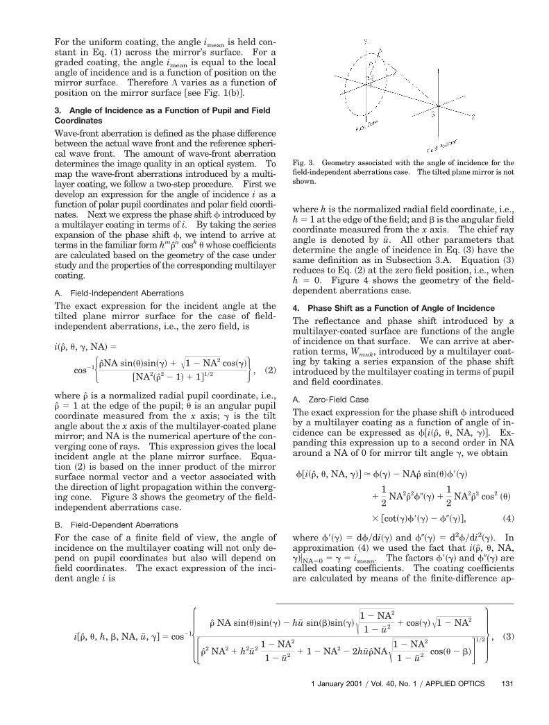
where r̂ is a normalized radial pupil coordinate, i.e.,r̂ 5 1 at the edge of the pupil; u is an angular pupilcoordinate measured from the x axis; g is the tiltangle about the x axis of the multilayer-coated planemirror; and NA is the numerical aperture of the con-verging cone of rays. This expression gives the localincident angle at the plane mirror surface. Equa-tion ~2! is based on the inner product of the mirrorsurface normal vector and a vector associated withthe direction of light propagation within the converg-ing cone. Figure 3 shows the geometry of the field-independent aberrations case.
B. Field-Dependent Aberrations
For the case of a finite field of view, the angle ofincidence on the multilayer coating will not only de-pend on pupil coordinates but also will depend onfield coordinates. The exact expression of the inci-dent angle i is
i@r̂, u, h, b, NA, u# , g# 5 cos215 r̂ NA sin~u!sin~g
Fr̂2 NA2 1 h2u# 2 1 2
1 2
where h is the normalized radial field coordinate, i.e.,h 5 1 at the edge of the field; and b is the angular fieldcoordinate measured from the x axis. The chief rayangle is denoted by u# . All other parameters thatdetermine the angle of incidence in Eq. ~3! have thesame definition as in Subsection 3.A. Equation ~3!reduces to Eq. ~2! at the zero field position, i.e., whenh 5 0. Figure 4 shows the geometry of the field-dependent aberrations case.
4. Phase Shift as a Function of Angle of Incidence
The reflectance and phase shift introduced by amultilayer-coated surface are functions of the angleof incidence on that surface. We can arrive at aber-ration terms, Wmnk, introduced by a multilayer coat-ing by taking a series expansion of the phase shiftintroduced by the multilayer coating in terms of pupiland field coordinates.
A. Zero-Field Case
The exact expression for the phase shift f introducedy a multilayer coating as a function of angle of in-idence can be expressed as f@i~r̂, u, NA, g!#. Ex-anding this expression up to a second order in NAround a NA of 0 for mirror tilt angle g, we obtain
f@i~r̂, u, NA, g!# < f~g! 2 NAr̂ sin~u!f9~g!
112
NA2r̂2f0~g! 112
NA2r̂2 cos2 ~u!
3 @cot~g!f9~g! 2 f0~g!#, (4)
here f9~g! 5 dfydi~g! and f0~g! 5 d2fydi2~g!. Inapproximation ~4! we used the fact that i~r̂, u, NA,g!uNA50 5 g 5 imean. The factors f9~g! and f0~g! arecalled coating coefficients. The coating coefficientsare calculated by means of the finite-difference ap-
u# sin~b!sin~g!Î1 2 NA2
1 2 u# 2 1 cos~g!Î1 2 NA2
1 1 2 NA2 2 2hu# r̂NAÎ1 2 NA2
1 2 u# 2 cos~u 2 b!G1y26 , (3)
Fig. 3. Geometry associated with the angle of incidence for thefield-independent aberrations case. The tilted plane mirror is notshown.
! 2 h
NA2
u# 2
1 January 2001 y Vol. 40, No. 1 y APPLIED OPTICS 131

w
i
wp
tawapi
1
proximation. The required values of f~i! are com-puted with a matrix formalism for the modeling ofthin-film coatings.8
B. Finite-Field Case
For the case of a finite field of view, the phase shiftintroduced by the multilayer coating as a function ofthe incidence angle can be expressed as f@i~r̂, u, h, b,NA, u# , g!#. Taking the series expansion around botha NA of 0 and u# 5 0 at a plane mirror tilt angle g, weobtain
f@i~r̂, u, h, b, NA, u# , g!# <
f~g! 2 NAr̂ sin~u!f9~g! 112
NA2r̂2f0~g!
112
NA2r̂2 cos2~u!@cot~g!f9~g! 2 f0~g!#
1 hu# sin~b!f9~g! 112
h2u# 2@cot~g!cos2~b!f9~g!
1 sin2~b!f0~g!# 2 NAhu# r̂@cot~g!cos~b!cos~u!f9~g!
1 sin~b!sin~u!f0~g!#, (5)
here we used the fact that i~r̂, u, h, b, NA, u# ,g!uNA50,u# 50 5 g 5 imean. The coating coefficients
Fig. 4. Geometry associated with the angle of incidence for thefield-dependent aberrations case. The tilted plane mirror is notshown.
Fig. 5. Surface plots of W011, W020, and W022. ~a! The axis labeledat the edge of the pupil. A similar interpretation is applied to ~b
32 APPLIED OPTICS y Vol. 40, No. 1 y 1 January 2001
f9~g! and f0~g! have the same definition as in approx-mation ~4!.
5. Aberrations Introduced by a Multilayer Coating
A. Zero-Field Case
For the zero-field case we derived three field-independent aberration terms up to the second order:W011, a field-independent tilt; W020, a defocus term;and W022, a field-independent astigmatism. Begin-ning with the expansion of the phase shift in approx-imation ~4!,
W~r̂, u! 5 F2 l
2pNAf9~g!Gr̂ sin u 5 W011r̂ sin u, (6)
W~r̂, u! 5 F l
4pNA2f0~g!Gr̂2 5 W020r̂
2, (7)
W~r̂, u! 5 H l
4pNA2@cot~g!f9~g! 2 f0~g!#Jr̂2 cos2~u!
5 W022r̂2 cos2~u!. (8)
The parametric plots of these three aberration termsare shown in Fig. 5. Note that these plots show onlythe form of each aberration and not the magnitude ofeach aberration.
1. Uniform CoatingThe uniform coating is designed for a mean angle ofincidence, i.e., the period L is determined from Eq. ~1!
ith the mean angle of incidence independent of theosition on the optical surface.Figure 6 shows the variation of phase and reflec-
ance for both s and p polarizations as a function ofngle of incidence on a plane mirror tilted at 8.2 degith respect to the optical axis @see Fig. 2~a!#. Thengle of incidence is simply related to the normalizedupil variable r̂ by Eq. ~2!. Furthermore, we use
mean 5 8.2° in Eq. ~1!. The coating coefficients forthis case are calculated as described in Subsection4.A and are shown in Table 1.
Evaluation of Eqs. ~6!–~8! using the values in Table1, a NA of 0.1, at the edge of the pupil r̂ 5 1, awavelength of 13.4 nm, and the configuration in Fig.
measured in units of W011, the wave-front departure from a sphere~c!. The x and y axes represent normalized pupil coordinates.
W is! and

Trfp2tw
qFrvmg
circa
2~a!, we obtain the aberration coefficients for the uni-form multilayer coating. The results are listed inTable 2.
Fig. 7. Phase and reflectance introduced by a graded multilayershown as a solid curve, and the effect on p-polarized light is show
Table 1. Taylor-Series Expansion Coefficients of the Phase-ShiftDependence on Angle of Incidence for a Uniform Coating at a Mirror
Tilt Angle of 8.2-deg
Series CoefficientCoating Coefficient Value
~uniform coating!
f9~8.2°! 7.21 ~s!, 7.24 ~p!f0~8.2°!y2! 14.77 ~s!, 18.59 ~p! ~rad
21!
Table 2. Field-Independent Aberration Coefficients for a UniformCoating at an 8.2-deg Tilta
Coefficient
8.2-deg Mirror Tilt
s Polarized ~nm! p Polarized ~nm!
W011 21.538 21.544W020 0.315 0.397W022 0.219 0.139
aSee Fig. 2~a!.
Fig. 6. Phase and reflectance introduced by a uniform multilayera solid curve, and p-polarized light is shown as a dashed curve.
2. Graded CoatingFor a graded coating the angle imean is set to matchthe local incident angle i so that imean 5 i in Eq. ~1!.
he series expansions of f in i are taken around theeference angle of i 5 8.2°. The coating coefficients9 and f0 are calculated with a finite-difference ap-roximation. For the configuration shown in Fig.~b!, the phase shift and reflectance associated withhe graded multilayer coating are plotted in Fig. 7hich shows plots for both s- and p-polarized light.The advantage of graded multilayer coating is
ualitatively apparent when Fig. 7 is compared withig. 6. The reflectance stays high for a greaterange of incidence angles, and the phase-shift curvearies more slowly with angle of incidence. The nu-erical values of the coating coefficients for the
raded coating are shown in Table 3.The aberration coefficients for the graded coating
an be calculated by use of Eqs. ~6!–~8! with the datan Table 3. At a NA of 0.1, at the edge of the pupilˆ 5 1, and a wavelength of 13.4 nm, the aberrationoefficients for the graded coating at a mirror tiltngle of g 5 8.2° are given in Table 4.
ng. The graded multilayer coating’s effect on s-polarized light isa dashed curve.
ing at a mirror tilt angle of 8.2 deg. s-polarized light is shown as
coatin as
coat
1 January 2001 y Vol. 40, No. 1 y APPLIED OPTICS 133

sfimv
h
t
N
Table 3. Taylor-Series Expansion Coefficients of the Phase-Shift Table 5. Field-Dependent Aberration Coefficients for a Uniform
1
B. Finite-Field-of-View Case
For the case of a finite field of view, we studied onlythe uniform coating. We derived six aberrationterms up to the second order. In addition to thethree field-independent aberration terms already dis-cussed, we now also have a field-dependent pistonterm W100, a field-squared-dependent piston termW200, and an anamorphic magnification term that webreak into two parts, W111C and W111S. By manip-ulating the expression for the phase shift in approx-imation ~5!, we find that the terms have the followingforms:
W~r̂, u, h, b! 5 F l
2pu# f9~g!Gh sin~b! 5 W100h sin~b!,
(9)
W~r̂, u, h, b! 5 H l
4pu# 2@f9~g!cot~g!cos2~b!
1 f0~g!sin2~b!#Jh2
5 W200h2, (10)
W~r̂, u, h, b! 5 F2l
2pNAu# f9~g!cot~g!Ghr̂ cos~b!cos~u!
5 W111Chr̂ cos~b!cos~u!, (11)
W~r̂, u, h, b! 5 F2l
2pNAu# f0~g!Ghr̂ sin~b!sin~u!
5 W111Shr̂ sin~b!sin~u!. (12)
Using the values for the coating coefficients from Ta-ble 1 in Eqs. ~9!–~12!, h 5 1, u# 5 0.025 rad, a NA of0.1, and a wavelength of 13.4 nm, we obtain the ab-erration coefficients that are listed in Table 5.
6. Analysis
We have obtained analytical expression for the first-and second-order aberrations that are due to multi-
Dependence on Angle of Incidence for a Graded Coating at a Mirror TiltAngle of g 5 8.2°
Series CoefficientCoating Coefficient Value
~uniform coating!
f9~8.2°! 0.574 ~s!, 0.308 ~p!f0~8.2°!y2! 3.810 ~s!, 2.427 ~p! ~rad
21!
Table 4. Field-Independent Aberration Coefficients for the GradedCoating on a Plane Mirror and g 5 8.2°
Coefficient
8.2-deg Mirror Tilt
s Polarized ~nm! p Polarized ~nm!
W011 20.122 20.066W020 0.041 0.026W022 0.002 20.003
34 APPLIED OPTICS y Vol. 40, No. 1 y 1 January 2001
layer coatings. For the field-independent case, weanalyzed both a uniform and a graded multilayercoating. For the field-dependent case, we analyzedonly the uniform coating. Numerical results of ouranalysis in terms of the aberration coefficient mag-nitudes are given in Tables 2, 4, and 5 in Section 5.In this section we interpret and analyze some of thoseresults.
A. Uniform Coating versus Graded Coating
In the field-independent case the graded coating of-fers a superior performance to that of the uniformcoating. Aberration coefficients for both uniformand graded coatings are given in Tables 2 and 4.Note that the aberration coefficients for the gradedcoating are approximately ten times smaller thanthose associated with the uniform coating in the caseof the simple configuration of Fig. 2~a!.
B. Anamorphic Magnification
In the field-dependent case, we found two aberrationterms, W111C and W111S, that we collectively calledmultilayer anamorphic magnification. The effect ofthis multilayer anamorphic magnification is a differ-ence in transverse ray error ~deviation from theGaussian image point! in the horizontal directionalong the x axis versus the vertical direction along they axis ~see Fig. 4!. In general, if one starts with aquare grid then anamorphic magnification trans-orms the square grid into a rectangular grid. Tollustrate the effect of the multilayer anamorphic
agnification we calculated the associated trans-erse ray error in both the x and the y directions. Dx
is the maximum transverse ray error in the x ~ororizontal! direction, and Dy is the maximum trans-
verse ray error in the y ~or vertical! direction. Theransverse ray errors are
Dx 51
NAW111Ch, (13)
Dy 51
NAW111Sh. (14)
ote that Eqs. ~13! and ~14! correspond to the anglesb 5 0°, u 5 0° and b 5 90°, u 5 90°, respectively @seeFig. 4 and Eqs. ~11! and ~12!#.
To obtain a quantitative estimate of the differencebetween the transverse ray errors in the horizontal
Coating on a Plane Mirror Tilted at g 5 8.2°a
Coefficient
8.2-deg Mirror Tilt
s Polarized ~nm! p Polarized ~nm!
W100 0.384 0.386W200 0.033 0.033W111C 20.267 20.268W111S 20.157 20.198
aSee Fig. 2~b!.

1o
ul
ciFcmbv
psqo
aeawa
winistpm
e
1
i
s
direction and in the vertical direction, we again relyon the example configuration shown in Fig. 2~b!.Using the values of NA equaling 0.1, u# 5 0.025, h 5, i.e., edge of field, and a wavelength of 13.4 nm, webtain W111C 5 20.157, W111S 5 20.267, Dx~nm! 5
21.57, and Dy ~nm! 5 22.67.
C. Comparison with Lens Design Software
To test the analytical expressions for aberration co-efficients that we developed, we modeled the caseshown in Fig. 2~a!, i.e., the field-independent case,
sing both our analytical method and a commercialens design program ZEMAX.9
We first calculated the aberration coefficients usingthe analytical method developed in this paper. Nextwe modeled the nominal multilayer coating modifiedfor imean 5 8.2° in ZEMAX and obtained the aberrationcoefficients numerically. Figures 8 and 9 show plotsof the tangential and sagittal wave-front error as afunction of radial pupil position, respectively, calcu-lated by the analytical method and by ZEMAX. Onaverage, the results from our analytical methods andthe results from ZEMAX agreed within 2% of error.
7. Conclusions and Future Research
We have presented an analytical method of estimatingthe aberration coefficients for EUVL multilayer reflec-tion coatings deposited on a plane mirror. We studiedboth uniform and graded coatings in the case of a zerofield and derived the associated field-independent aber-rations. We also studied the uniform coating with afinite field of view and obtained the associated field-dependent aberrations. Using a simple optical system
Fig. 8. Tangential wave-front error versus pupil position. TheZEMAX result is shown as a dashed curve, and the analytical results shown as a solid curve.
Fig. 9. Sagittal wave-front error versus pupil position. The ZE-MAX result is shown as a dashed curve, and the analytical result ishown as a solid curve.
configuration @see Fig. 2~a!# for the field-independentase, we found that a graded coating introduced approx-mately ten times less aberration than a uniform coating.or the field-dependent case we showed that a multilayeroating can introduce anamorphic magnification. Theultilayer anamorphic magnification causes a difference
etween the transverse ray error in the horizontal andertical directions.The approach presented in this paper can be ap-
lied to a variety of geometries to estimate first- andecond-order effects of multilayer coatings on imageuality, distortion, and alignment associated with anptical system.One can model third- and higher-order effects an-
lytically using the method we have described byxtending the series expansion in approximations ~4!nd ~5! to higher-order terms. Although straightfor-ard conceptually, the calculation required is at leastn order of magnitude more complex.Powered surfaces can also be modeled by this methodith some modifications. An additional local angle of
ncidence and sag that are due to the radius of curvatureeed to be accounted for in the expression for the angle of
ncidence. Once the modified angle of incidence expres-ion is obtained, the aberration terms can be foundhrough exactly the same method as that used with alane mirror. The associated mathematical develop-ent is outside this scope of this paper.Mathematical derivations and calculations were
xecuted with the aid of a computer and the softwareMATHEMATICA.10 MATHEMATICA notebook files that con-tain the detailed derivations and calculations can beobtained by directly contacting the author.
In the future, we plan to expand the analysis presentedhere to include powered mirrors and mirror systems thatcontain multiple multilayer-coated mirrors.
References1. D. J. Reiley and R. A. Chipman, “Coating-induced wave-front
aberrations: on-axis astigmatism and chromatic aberrationin all-reflecting systems,” Appl. Opt. 33, 2002–2012 ~1994!.
2. T. E. Jewell, “Effect of amplitude and phase dispersion onimages in multilayer-coated soft-x-ray projection systems,” inSoft-X-Ray Projection Lithography, J. Bokor, ed., Vol. 12 ofOSA Proceedings Series ~Optical Society of America, Washing-ton, D.C., 1991!, pp. 113–188.
3. N. J. Duddles, “Effects of MoySi multilayer coatings on theimaging characteristics of an extreme-ultraviolet lithographysystem,” Appl. Opt. 37, 3533–3538 ~1998!.
4. Code V is a product of Optical Research Associates, Pasadena,Calif. ~1999!.
5. Y. Watanabe, M. Suzuki, N. Mochizuki, M. Niibe, and Y.Fukuda, “Optical design for soft x-ray projection lithography,”Jpn. J. Appl. Phys. 30, 3053–3057 ~1991!.
6. Center for X-Ray Optics ~CXRO!, http:yycindy.lbl.govyoptical_constants ~1998!.
7. J. E. Bjorkholm, “Reduction imaging at 14 nm usingmultilayer-coated optics: printing of features smaller than0.1 um,” J. Vac. Sci. Technol. B 8, 1509–1513 ~1990!.
8. A. H. Macleod, Thin-Film Optical Filters, 2nd ed. ~Hilger, Lon-don, 1986!.
9. ZEMAX is a product of Focus Software, Inc., Tucson, Ariz. ~1999!.0. MATHEMATICA is a product of Wolfram Research, Inc., Cham-
paign, Ill. ~1999!.
1 January 2001 y Vol. 40, No. 1 y APPLIED OPTICS 135