Embed Size (px)
Citation preview
Multigram synthesis of copper nanowires using ac electrodeposition intoporous aluminium oxide templates
Genaro A. Gelves, Zakari T. M. Murakami, Matthew J. Krantz and Joel A. Haber*
Received 7th March 2006, Accepted 15th May 2006
First published as an Advance Article on the web 31st May 2006
DOI: 10.1039/b603442j
Multigram quantities of Cu nanowires ca. 25 nm in diameter and mm in length have been
produced by AC electrodeposition into porous aluminium oxide (PAO) templates. Multiple,
large-area Al electrodes (5 6 11 cm or 10 6 25 cm) are anodized in parallel at 25.0 V in 0.3 M
H2SO4(aq) using custom built baths. The pores are efficiently filled by applying 200 Hz sine waves
at 10 Vrms between the anodized Al and Cu plate counter electrodes immersed in a 0.50 M
CuSO4(aq) solution. Dissolution of the PAO template in 0.6 M H3PO4 to free the Cu nanowires
results in significant coarsening of the nanowires, whereas dissolution of the PAO template in
1.0 M NaOH(aq) results in retention of the Cu nanowire diameters corresponding to the pore
diameter of the PAO template. Liberated Cu nanowires were characterized by scanning electron
microscopy, X-ray diffraction, and X-ray photoelectron spectroscopy.
Introduction
The synthesis and applications of nanowires, nanobelts, nano-
rods, and related nanostructures has recently been reviewed.1
In the past few years, significant advances have been made in
the solution-based synthesis of metal nanorods and nanowires.
In particular, Murphy and co-workers have demonstrated
great control over the aspect ratio and surface chemistry of
gold nanorods and nanowires, using a surfactant mediated
technique.2–6 Xia’s and several other groups have developed
solution based techniques to synthesize high aspect ratio silver
nanowires.1,7–17 The relative rarity and expense of these
metals may preclude the widespread use of these nanowires
in engineering polymer composites, for instance. Recently, a
solution-based synthesis of high aspect-ratio copper nanowires
has been reported.18 This method appears promising, but
relatively large nanowire diameters (90–120 nm) are obtained.
Template-directed syntheses in the pores of porous alumi-
nium oxide (PAO) or track-etched polymer membranes have
been widely used to produce uniformly sized nanofibers and
nanowires of many materials and composite structures.19–22 As
described in the references given below, DC and AC
electrodeposition of metals into PAO templates has been
investigated for decades. Liberation of the metal nanoparticles
by dissolution of the alumina has been used to produce small
quantities (¡1 mg) of metal nanoparticles or metal nanowires
whose fundamental properties and applications have been
investigated (notably by Moskovits, Martin, Masuda,
Mallouk, and Gosele, as well as others). The well-developed
approach of DC electrodeposition of metals into PAO
template membranes affords control over the crystallinity of
nanowires23–28 and enables precise modulation of the compo-
sition along the length of the nanowire.29–36 These nanowires
display a plethora of interesting properties with diverse
applications.26,29–42 Unfortunately, the multiple processing
steps required to produce the rather fragile free-standing
PAO membranes and then to prepare electrodes suitable for
DC electrodeposition may prevent this method from being
used to produce metal nanowires in sufficient quantity for
many potential applications.
The less developed approach of AC electrodeposition into
PAO templates through the resistive, rectifying barrier layer
without separation from the Al substrate also affords good
quality filling of the pores with single metals, if optimized
electrodeposition conditions are used.43–54 High uniformity of
deposition has been demonstrated by the group of Gosele
using current-controlled deposition sequences.45,49,52 We have
elected to develop voltage-controlled deposition sequences,
due to this method’s insensitivity to electrode area. We have
previously reported a detailed study of the effect of electro-
deposition parameters upon the uniformity of pore-filling of
PAO templates with copper,55 and have communicated the
preparation of polymer nanocomposites containing Cu nano-
wires prepared using AC electrodeposition into PAO tem-
plates.56 We believe that it is technically feasible to produce kg
quantities of metal nanowires using the ac electrodeposition
process, as the anodization and electrodeposition processes are
fundamentally similar to the Anolok1 process (a trademark
of Alcan International Ltd) that is used to anodize and
then colorize by metal deposition large Al pieces (7 6 1.8 m)
for architectural applications (http://www.hmfltd.co.uk).
Although the Anolok1 process does not produce well-ordered
pores and the quantity of metal deposited is small (little metal
is required for colorization), straightforward adoption of the
processes reported herein could be implemented.
Polymer matrix nanocomposites containing nanodisperse
fillers such as exfoliated clays, carbon black, multi-walled and
single-walled fullerene nanotubes, and metal nanoparticles
have received great and increasing attention due to their
combination of processibility with enhanced or unique barrier,
electrical, mechanical, or bioactive properties.57–64 RelativelyDepartment of Chemistry, University of Alberta, Edmonton, Alberta,Canada T6G 2G2. E-mail: [email protected]
PAPER www.rsc.org/materials | Journal of Materials Chemistry
This journal is � The Royal Society of Chemistry 2006 J. Mater. Chem., 2006, 16, 3075–3083 | 3075
Dow
nloa
ded
by U
nive
rsity
of
Ten
ness
ee a
t Kno
xvill
e on
07
Mar
ch 2
013
Publ
ishe
d on
31
May
200
6 on
http
://pu
bs.r
sc.o
rg |
doi:1
0.10
39/B
6034
42J
View Article Online / Journal Homepage / Table of Contents for this issue
little investigated are polymer matrix nanocomposites contain-
ing nanowires composed of metals, likely due to the lack of
synthetic methods suitable for producing even gram quantities
of nanowires. Were gram quantities of metal nanowires
available inexpensively, the combination of their high thermal
and electrical conductivity and the potential ease of modifying
their surface properties by surface functionalization with small
molecule thiols, amines, and carboxylates would afford
numerous opportunities for tuning and enhancing properties
in applications such as polymer matrix nanocomposites. We
have developed a simple, scalable, versatile, bench-top electro-
synthesis of gram quantities of high-aspect ratio Cu nanowires.
With appropriate modification of the electrodeposition condi-
tions, the process described here could be applied to the
multigram synthesis of other metals and compound nanowires.
Experimental
Herein we describe somewhat different processing conditions
for two differently sized Al electrodes for growth of the PAO
films and for electrodeposition to deposit the Cu nanowires.
Electrode preparation
For the smaller scale process, aluminium electrodes were pre-
pared by cutting Al plate (99.99+%, Alfa Aesar, 1 mm thick)
into 5 6 11 cm pieces, which were annealed at 500 uC in air for
24 h. The electrodes were etched in 60 uC, 1.0 M NaOH(aq) for
2 min, and both faces immediately electropolished in a 1 uCdouble-walled, cooled cylindrical bath containing 500 mL of
solution consisting of a mixture of 115 mL 70% perchloric
acid, 90 mL 2-butoxyethanol, 600 mL ethanol and 150 mL
water. Graphite foil (99%, Alfa Aesar, 1 mm thick) was used
for the counter electrodes (one on each side of the Al, 2 cm
from and parallel to the Al face), with electrical contacts made
using copper alligator clips. Three pulses with a current density
of 280 mA cm22 and 15 s duration were applied with a 5 min
period between pulses to allow the bath to cool to 1 uC.
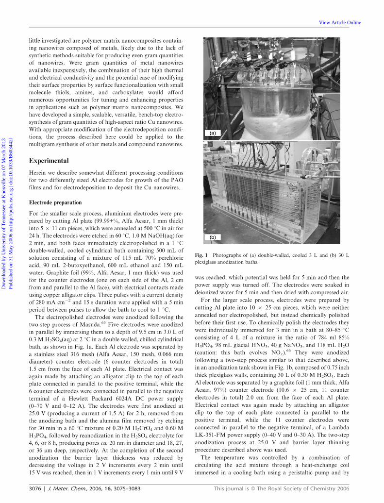
The electropolished electrodes were anodized following the
two-step process of Masuda.65 Five electrodes were anodized
in parallel by immersing them to a depth of 9.5 cm in 3.0 L of
0.3 M H2SO4(aq) at 2 uC in a double walled, chilled cylindrical
bath, as shown in Fig. 1a. Each Al electrode was separated by
a stainless steel 316 mesh (Alfa Aesar, 150 mesh, 0.066 mm
diameter) counter electrode (6 counter electrodes in total)
1.5 cm from the face of each Al plate. Electrical contact was
again made by attaching an alligator clip to the top of each
plate connected in parallel to the positive terminal, while the
6 counter electrodes were connected in parallel to the negative
terminal of a Hewlett Packard 6024A DC power supply
(0–70 V and 0–12 A). The electrodes were first anodized at
25.0 V (producing a current of 1.5 A) for 2 h, removed from
the anodizing bath and the alumina film removed by etching
for 30 min in a 60 uC mixture of 0.20 M H2CrO4 and 0.60 M
H3PO4, followed by reanodization in the H2SO4 electrolyte for
4, 6, or 8 h, producing pores ca. 20 nm in diameter and 18, 27,
or 36 mm deep, respectively. At the completion of the second
anodization the barrier layer thickness was reduced by
decreasing the voltage in 2 V increments every 2 min until
15 V was reached, then in 1 V increments every 1 min until 9 V
was reached, which potential was held for 5 min and then the
power supply was turned off. The electrodes were soaked in
deionized water for 5 min and then dried with compressed air.
For the larger scale process, electrodes were prepared by
cutting Al plate into 10 6 25 cm pieces, which were neither
annealed nor electropolished, but instead chemically polished
before their first use. To chemically polish the electrodes they
were individually immersed for 3 min in a bath at 80–85 uCconsisting of 4 L of a mixture in the ratio of 784 ml 85%
H3PO4, 98 mL glacial HNO3, 40 g NaNO3, and 118 mL H2O
(caution: this bath evolves NOx).66 They were anodized
following a two-step process similar to that described above,
in an anodization tank shown in Fig. 1b, composed of 0.75 inch
thick plexiglass walls, containing 30 L of 0.30 M H2SO4. Each
Al electrode was separated by a graphite foil (1 mm thick, Alfa
Aesar, 97%) counter electrode (10.6 6 25 cm, 11 counter
electrodes in total) 2.0 cm from the face of each Al plate.
Electrical contact was again made by attaching an alligator
clip to the top of each plate connected in parallel to the
positive terminal, while the 11 counter electrodes were
connected in parallel to the negative terminal, of a Lambda
LK-351-FM power supply (0–40 V and 0–30 A). The two-step
anodization process at 25.0 V and barrier layer thinning
procedure described above was used.
The temperature was controlled by a combination of
circulating the acid mixture through a heat-exchange coil
immersed in a cooling bath using a peristaltic pump and by
Fig. 1 Photographs of (a) double-walled, cooled 3 L and (b) 30 L
plexiglass anodization baths.
3076 | J. Mater. Chem., 2006, 16, 3075–3083 This journal is � The Royal Society of Chemistry 2006
Dow
nloa
ded
by U
nive
rsity
of
Ten
ness
ee a
t Kno
xvill
e on
07
Mar
ch 2
013
Publ
ishe
d on
31
May
200
6 on
http
://pu
bs.r
sc.o
rg |
doi:1
0.10
39/B
6034
42J
View Article Online
circulating cooling fluid through glass radiators immersed on
both sides of the anodizing tank. Keeping the bath at 0–4 uCis critical to maintain a constant anodization current. If the
bath heats up to above 4 uC, the chemical etch rate at the
pore bottom increases, reducing the barrier layer thickness,
enabling the anodization current to increase and producing a
runaway feedback loop, until the current limit of the power
supply is reached. At this point the voltage decreases and
moves away from the conditions that enable attainment of
good pore-ordering. Extra circulation of the anodizing
solution was provided by two mechanical stirrers in addition
to the circulation of the solution with the peristaltic pump.
Electrodeposition of Cu
The pores of the alumina films were filled with Cu using ac
electrodeposition. The edges and top boundary of the anodized
electrodes were coated with nail polish. This is necessary
because micrometer sized cracks formed at all 90u edges
provide a low resistance deposition pathway that prevents
deposition into the 25 nm diameter pores, if exposed to the
deposition solution. Previously, ultrasound was used to
improve wetting of the pores prior to electrodeposition;55
however, this step was eliminated because we found it
damaged the surface of the electrodes and reduced our ability
to reuse the Al plates. Electrodes were wet with distilled water
and then individually immersed for 5 min in the deposition
solution consisting of 600 mL (for 5 6 11 cm electrodes) or 4 L
(for 10 6 25 cm electrodes) of 0.50 M CuSO4–0.285 M
H3BO3(aq). Each electrode was filled by applying a continuous
200 Hz sine wave at 10 Vrms for 10–15 min between the
anodized Al and Cu plate (99.999%, Alfa Aesar) counter
electrodes 2 cm from both faces of the Al electrode. The
deposition signal was generated using a Tabor Electronics
8023 function generator, the output of which was amplified
with a 1600 W Pyramid PB1281X car stereo amplifier powered
with a LOKO 45 A, 16 V DC power supply or a car battery.
The nail polish was removed from the edges of the electrodes
with acetone. Bulk Cu deposition was removed by immersing
the electrode in 60 uC, 0.6 M H3PO4 for 1 min, followed by
cleaning the surface with a Kimwipe.
Liberation of Cu nanowires
Two methods for dissolving the PAO template to liberate the
nanowires have been used. The first method attempted was
dissolution of the alumina in 60 uC, 0.6 M H3PO4(aq) for
30 min; however, this method produced significant coarsening
of the nanowires. Therefore, the second method of dissolving
the alumina in 40 uC, 1.0 M NaOH(aq) for 3 min is preferred.
The nanowires were cleaned for 10 min in a 1 : 1 mixture
of 0.10 M NaOH(aq)–MeOH, filtered using filter paper
(Whatman, ,1 mm pore size), rinsed with methanol, and
transferred to a volume of 100 or 250 ml of methanol. The
nanowires were then sonicated for a period of 1 h in a
sonication bath of 135 W average power and 38.5–40.5 kHz
frequency by applying the ultrasound for 5 min with a 5-min
rest period between sonications. After sonication, dispersed
copper nanowires were collected by filtration on Osmonics Inc.
nylon membranes (0.45 mm pore size) and dried under reduced
pressure. Yield: 0.87 mg cm22 (ca. 0.39 g per batch of
5 electrodes) for 4 h anodized and 1.68 mg cm22 (ca. 0.75 g per
batch of 5 electrodes) for the 8 h anodized 5 6 11 cm
electrodes and ca. 0.8–1.4 mg cm22 (ca. 3.5–6.2 g per batch of
10 electrodes) for the 10 6 25 cm electrodes anodized for 8 h.
Length distribution of NaOH-liberated Cu nanowires
Copper nanowires were grown in pores anodized for 8 h using
5 6 11 cm electrodes, and liberated using 1.0 M NaOH(aq).
The Cu nanowires were cleaned and sonicated as described
above. The resultant suspension of Cu nanowires in MeOH
was spin cast at 3000 rpm on 2.5 6 2.5 cm glass slides. SEM
images were collected of the well-dispersed nanowires and the
lengths of >1000 individual nanowires was measured using the
Image J image analysis software program (Wayne Rasband,
National Institutes of Health, USA, http://rsb.info.nih.gov/ij).
Preparation of nanowire samples for XPS and XRD analysis
Suspensions of Cu nanowires in MeOH obtained from the
liberation process were dried under reduced pressure in glass
vials containing 1 6 1 cm silicon wafers on the bottom. The
nanowires sedimented and dried onto the Si slide. The X-ray
photoelectron spectra (XPS) and XRD patterns were imme-
diately collected, limiting air exposure to ,30 min. The
diffraction peak of the silicon wafer was removed by excluding
the diffraction spot arising from the single crystal silicon
from the integration of the 2D image of X-ray diffraction to
produce the 2h plot.
Depth profiling of pore-filling
Following electrodeposition into 5 6 11 cm electrodes the
surfaces were cleaned (0.5 mm removed from the surface) or
ion-milled (10 mm removed from the surface) using an Oxford
Ion Fab 300+ ion mill. The surfaces were characterized by
SEM, and the percentage of pores filled to the top of the new
surface was determined using the cell counter plugin developed
for ImageJ 1.35j image analysis software (Wayne Rasband,
National Institutes of Health, USA, http://rsb.info.nih.gov/ij).
Instrumentation
Characterization of the liberated nanowires was accomplished
by scanning electron microscopy (SEM) using a JEOL 6301F
FESEM equipped with an energy dispersive X-ray spectro-
meter (EDX), X-ray diffraction (XRD) using a Bruker AXS
D8 Discover with GADDS detector, X-ray photoelectron
spectroscopy (XPS) with a Kratos Axis Ultra or Kratos Axis
165 spectrometer, and transmission electron microscopy
(TEM) using a JEOL 2010 equipped with a CCD camera
and EDX spectrometer.
Results and discussion
Results
As briefly described previously,56 gram quantities of ca. 25 nm
diameter Cu nanowires are produced by AC electrodeposition
into porous aluminium oxide (PAO) films followed by
dissolution of the alumina in 1.0 M NaOH(aq) (preferred) or
This journal is � The Royal Society of Chemistry 2006 J. Mater. Chem., 2006, 16, 3075–3083 | 3077
Dow
nloa
ded
by U
nive
rsity
of
Ten
ness
ee a
t Kno
xvill
e on
07
Mar
ch 2
013
Publ
ishe
d on
31
May
200
6 on
http
://pu
bs.r
sc.o
rg |
doi:1
0.10
39/B
6034
42J
View Article Online
in 0.6 M H3PO4(aq). Slightly different processes have been
developed for two different size Al electrodes (see the
Experimental section for details). In the smaller scale process
both faces of five 5 6 11 cm, 1.0 mm thick Al electrodes
interdigitated between stainless steel mesh counter electrodes
are anodized in a chilled 3.0 L bath using the method of
Masuda,65 Fig. 1a. In the larger scale process, both faces of
ten 10 6 25 cm, 1.0 mm thick Al electrodes interdigitated
between graphite foil counter electrodes were anodized in a
chilled 30 L bath, Fig. 1b.
Anodization of large-area electrodes. In previous work
anodizing small-area Al electrodes (1 6 1.5 cm),55 we observed
that these electrodes would frequently ‘‘burn-out’’; that is,
anodize rapidly at a defect by shunting all current to that
point, resulting in formation of a pit, and preventing uniform
anodization of the remainder of the electrode. This was an
especially common occurrence at the solution/air interface
when anodizing bare Al plate electrodes. To prevent this,
we found it helpful to make sure that the electrodes were free
of deep scratches or other obvious defects and to paint a
protective line of epoxy or nail-polish around the Al plate
at the level of the solution/air interface. In contrast, the
large-area electrodes described here are far less susceptible to
‘‘burn-out’’, so it is not necessary to protect the electrodes at
the solution/air interface.
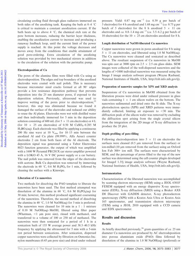
AC electrodeposition into PAO on large area electrodes.
Micrometer-sized edge cracks. Anodization of both faces of
bare Al plate results in the formation of ca. 10 micrometer
sized cracks on all 90u edges as a result of the volume
expansion accompanying conversion of Al to Al2O3 (Fig. 2a).
If these edge-cracks are not coated before electrodepositon
under continuous ac conditions, most Cu will be deposited in
them, because the diffusion limitation into the ca. 10 mm
diameter cracks is far less than the diffusion limitation into the
ca. 20 nm diameter, 18 or 36 mm deep pores (Fig. 2b). Pulsed
electrodeposition conditions may be used to minimize the
effect of this parasitic pathway by introducing a ‘‘hold-time’’
between deposition pulses to allow diffusion of Cu2+ into the
pores, but at the expense of greatly increasing the time
required for the electrodeposition to be completed. We have
found it to be more efficient to coat the edges of the electrodes
with nail polish to cover the cracks and prevent electro-
deposition and enable continuous AC conditions to be used.
The nail polish is easily removed with acetone after the
electrodeposition.
Effect of counter electrode on stability of deposition solution
and yield. In prior work using small-area electrodes we utilized
platinum or stainless steel counter-electrodes immersed in a
similar CuSO4(aq) solution (the H3BO3 was 0.57 vs. 0.285 M in
the present work).55 However, for these large-area electrodes
we observed that the deposition solution could only be used
once or twice before deposition quality was adversely affected
and the yield of Cu nanowires decreased substantially. We
observed that the pH decreased with each electrode filled with
Cu, we believe as a result of oxidation of water occurring at
the counter electrode during the reduction of Cu in the PAO.
By using Cu counter electrodes, we do not deplete the Cu2+
concentration in the solution and the pH is stable for
deposition into tens of electrodes, as dissolution of Cu is the
most favorable electrochemical process. In addition, the
deposition time is shorter using Cu counter electrodes than
when using stainless steel counter electrodes.
Effect of pore depth on yield. The fraction of pores filled as a
function of depth beneath the initial electrode surface is
comparable to that reported previously for small-area electro-
des (1 6 1.5 cm) filled using pulsed sine wave electrodeposition
conditions, except that the pores described here are deeper.
The fraction of pores filled 0.5 mm below the surface of 8 h
anodized (ca. 36 mm deep pores) is ca. 20% (Fig. 3a), while the
fraction filled to a level 10 mm below the initial surface is 60%
(Fig. 3b). As shown in Fig. 4, for the 5 6 11 cm electrodes,
the mass of nanowires produced per cm2 of electrode area
increases approximately linearly with pore depth, over the
range of anodization times investigated (4, 6 and 8 h corres-
ponding to 18, 27 and 36 mm deep pores, respectively).
Fig. 2 SEM of (a) micron size crack that forms on 90 degree edges
and (b) the bulk deposition of Cu that occurs at the crack if it is not
covered.
3078 | J. Mater. Chem., 2006, 16, 3075–3083 This journal is � The Royal Society of Chemistry 2006
Dow
nloa
ded
by U
nive
rsity
of
Ten
ness
ee a
t Kno
xvill
e on
07
Mar
ch 2
013
Publ
ishe
d on
31
May
200
6 on
http
://pu
bs.r
sc.o
rg |
doi:1
0.10
39/B
6034
42J
View Article Online

Effect of electrode size on yield. One of the limitations we
have encountered in the scale-up of the process is our ability to
supply sufficient current during each deposition pulse. In
particular, during the first seconds of electrodeposition a much
higher current is required, because the bulk concentration
of Cu2+ is present at the pore bottoms. As the deposition
continues, the Cu2+ concentration decreases to some steady-
state value and a lower current is required. However, it
appears that this initial, high-current period is critical to
nucleating and depositing Cu in all of the pore bottoms. The
amplifier we used is limited to Irms 30 A peak current (before it
goes into protection mode). The smaller 5 6 11 cm electrodes
initially require Idc 15 A current (measured dc current supplied
to the amplifier) which declines to a steady-state Idc 5 A
current after 60 s. The larger 10 6 25 cm electrodes required
Idc > 30 A current initially, and declined to a steady-state
current of Idc 15–20 A after 60 s. We observe a higher yield
with the 5 6 11 cm electrodes (1.68 mg cm22, ca. 0.15 g per
electrode, ca. 0.75 g per batch) than for the larger 10 6 25 cm
electrodes (0.8–1.4 mg cm22, ca. 0.35–0.62 g per electrode, ca.
3.5–6.2 g per batch)—the yield per cm2 for the 10 6 25 cm
electrodes was only 50–80% of the yield obtained for the
smaller electrodes.
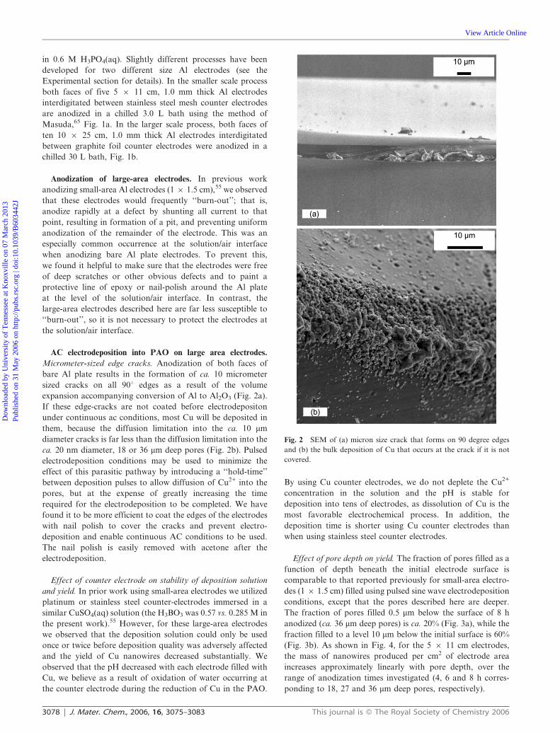
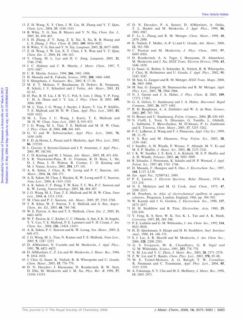
Effect of liberation process on morphology and dispersion.
Scanning electron microscopy indicates that the nanowires
liberated by dissolving the PAO template in 0.6 M H3PO4
[Fig. 5 (a–b)] are significantly less well dispersed than those
liberated by dissolving the PAO template in 1.0 M NaOH(aq)
[Fig. 5 (c–d)]. In addition, the morphology of copper
nanowires liberated using H3PO4 does not replicate that of
the porous alumina templates used. An average diameter of
69 ¡ 19 nm for H3PO4-liberated nanowires indicates a
significant increase in diameter (coarsening) when compared
to the average diameter of 25 ¡ 4 nm for nanowires liberated
in NaOH. In addition, the H3PO4-liberated nanowires display
noticeable oscillations in diameter along the nanowire length.
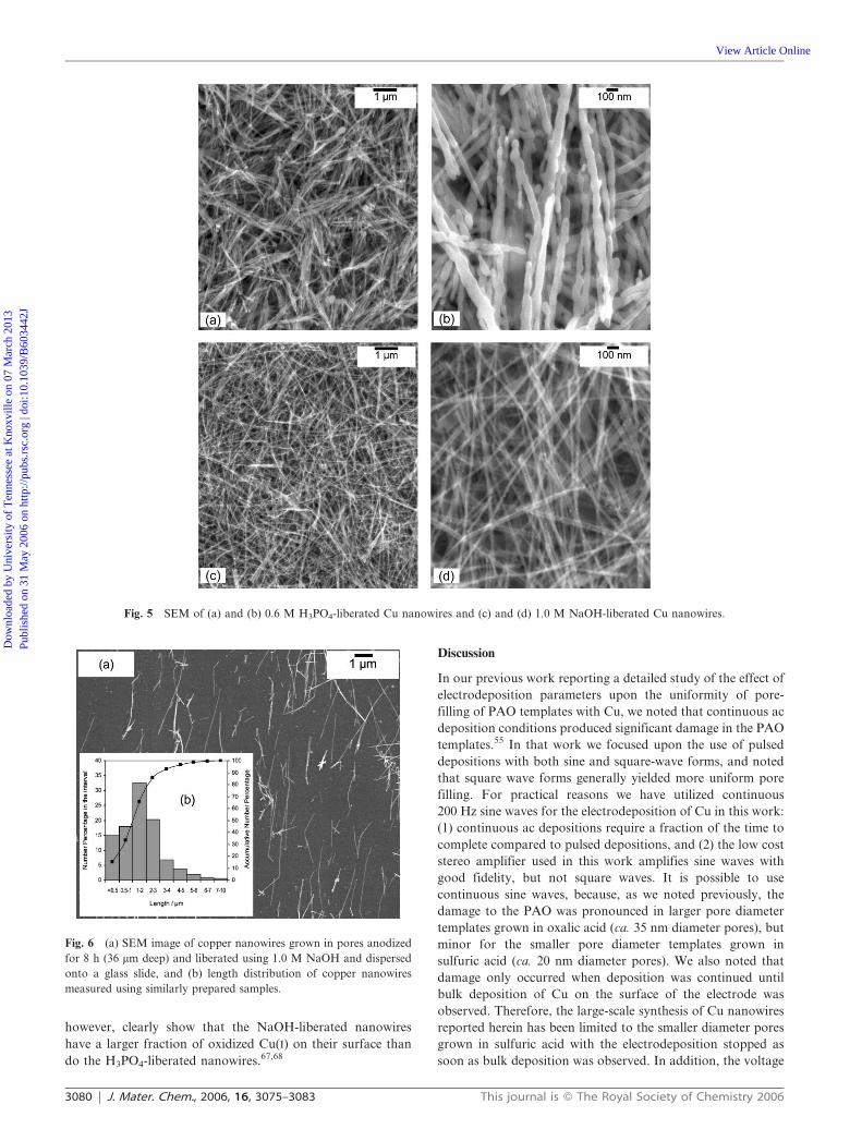
Although the pores of the PAO template are quite well filled
to depths of 30 mm, the length of the liberated nanowires is
significantly less. As shown in Fig. 6, even when grown in
pores ca. 36 mm deep, after fragmentation during the liberation
process the average nanowire length is ca. 2 mm and 90% of the
nanowires are ,3 mm in length. For these 25 nm diameter
wires, however, this still translates into an average aspect ratio
of ca. 80.
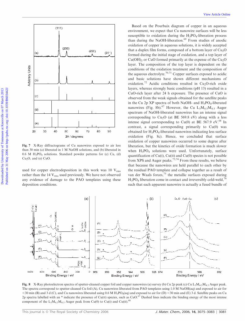
XRD patterns collected of nanowires immediately after
liberation (,30 min of air exposure) by both methods show no
evidence of oxides, CuO or Cu2O (Fig. 7). XPS collected
immediately after liberation (,30 min air exposure) indicates
little surface oxidation of the nanowires liberated by either
method (Fig. 8). The presence of surface oxide (CuO) is more
evident, as detected by XPS, after exposure of the liberated
copper nanowires to atmosphere for 3 d, but the nanowires
remain largely unoxidized. The Cu L3M4.5M4.5 Auger spectra
in Fig. 8c for nanowires exposed to air for ,30 min or 3 d,
Fig. 3 SEM images of top surfaces of ion-milled Cu-filled templates
(5 6 11 cm electrodes) to show degree of pore-filling as a function
of depth: (a) 0.5 and (b) 10 mm removed from the top of the 36 mm
deep-pores.
Fig. 4 Yield of Cu nanowires from PAO templates prepared by
anodization for different time in 0.3 M H2SO4 solutions (4, 6 or 8 h).
This journal is � The Royal Society of Chemistry 2006 J. Mater. Chem., 2006, 16, 3075–3083 | 3079
Dow
nloa
ded
by U
nive
rsity
of
Ten
ness
ee a
t Kno
xvill
e on
07
Mar
ch 2
013
Publ
ishe
d on
31
May
200
6 on
http
://pu
bs.r
sc.o
rg |
doi:1
0.10
39/B
6034
42J
View Article Online
however, clearly show that the NaOH-liberated nanowires
have a larger fraction of oxidized Cu(I) on their surface than
do the H3PO4-liberated nanowires.67,68
Discussion
In our previous work reporting a detailed study of the effect of
electrodeposition parameters upon the uniformity of pore-
filling of PAO templates with Cu, we noted that continuous ac
deposition conditions produced significant damage in the PAO
templates.55 In that work we focused upon the use of pulsed
depositions with both sine and square-wave forms, and noted
that square wave forms generally yielded more uniform pore
filling. For practical reasons we have utilized continuous
200 Hz sine waves for the electrodeposition of Cu in this work:
(1) continuous ac depositions require a fraction of the time to
complete compared to pulsed depositions, and (2) the low cost
stereo amplifier used in this work amplifies sine waves with
good fidelity, but not square waves. It is possible to use
continuous sine waves, because, as we noted previously, the
damage to the PAO was pronounced in larger pore diameter
templates grown in oxalic acid (ca. 35 nm diameter pores), but
minor for the smaller pore diameter templates grown in
sulfuric acid (ca. 20 nm diameter pores). We also noted that
damage only occurred when deposition was continued until
bulk deposition of Cu on the surface of the electrode was
observed. Therefore, the large-scale synthesis of Cu nanowires
reported herein has been limited to the smaller diameter pores
grown in sulfuric acid with the electrodeposition stopped as
soon as bulk deposition was observed. In addition, the voltage
Fig. 5 SEM of (a) and (b) 0.6 M H3PO4-liberated Cu nanowires and (c) and (d) 1.0 M NaOH-liberated Cu nanowires.
Fig. 6 (a) SEM image of copper nanowires grown in pores anodized
for 8 h (36 mm deep) and liberated using 1.0 M NaOH and dispersed
onto a glass slide, and (b) length distribution of copper nanowires
measured using similarly prepared samples.
3080 | J. Mater. Chem., 2006, 16, 3075–3083 This journal is � The Royal Society of Chemistry 2006
Dow
nloa
ded
by U
nive
rsity
of
Ten
ness
ee a
t Kno
xvill
e on
07
Mar
ch 2
013
Publ
ishe
d on
31
May
200
6 on
http
://pu
bs.r
sc.o
rg |
doi:1
0.10
39/B
6034
42J
View Article Online
used for copper electrodeposition in this work was 10 Vrms
rather than the 14 Vrms used previously. We have not observed
any evidence of damage to the PAO templates using these
deposition conditions.
Based on the Pourbaix diagram of copper in an aqueous
environment, we expect that Cu nanowire surfaces will be less
susceptible to oxidation during the H3PO4-liberation process
than during the NaOH-liberation.69 From studies of anodic
oxidation of copper in aqueous solutions, it is widely accepted
that a duplex film forms, composed of a bottom layer of Cu2O
formed during the initial stage of oxidation, and a top layer of
Cu(OH)2 or CuO formed primarily at the expense of the Cu2O
layer. The composition of the top layer is dependent on the
conditions of the oxidation treatment and the composition of
the aqueous electrolyte.70,71 Copper surfaces exposed to acidic
and basic solutions have shown different mechanisms of
oxidation.72 Acidic conditions resulted in Cu2O-rich oxide
layers, whereas strongly basic conditions (pH 13) resulted in a
CuO-rich layer after 24 h exposure. The presence of CuO is
observed from the weak signals obtained for the satellite peaks
in the Cu 2p XP spectra of both NaOH- and H3PO4-liberated
nanowires (Fig. 8b).67 However, the Cu L3M4.5M4.5 Auger
spectrum of NaOH-liberated nanowires has an intense signal
corresponding to Cu2O (at BE 569.8 eV) along with a less
intense signal corresponding to Cu(0) at BE 567.9 eV.68 In
contrast, a signal corresponding primarily to Cu(0) was
obtained for H3PO4-liberated nanowires indicating less surface
oxidation (Fig. 8c). Hence, we concluded that surface
oxidation of copper nanowires occurred to some degree after
liberation, but the kinetics of oxide formation is much slower
when H3PO4 solutions were used. Unfortunately, surface
quantification of Cu(I), Cu(II) and Cu(0) species is not possible
from XPS and Auger peaks.73,74 From these results, we believe
that because the nanowires are held parallel to each other by
the residual PAO template and collapse together as a result of
van der Waals forces,75 the metallic surfaces exposed during
H3PO4 liberation come in contact and irreversibly cold-weld,76
such that each apparent nanowire is actually a fused bundle of
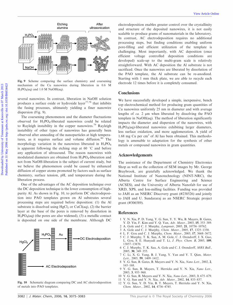
Fig. 8 X-Ray photoelectron spectra of sputter-cleaned copper foil and copper nanowires (a) survey (b) Cu 2p peak (c) Cu L3M4.5M4.5 Auger peak.
The spectra correspond to sputter-cleaned Cu foil (A), Cu nanowires liberated from PAO templates using 1.0 M NaOH(aq) and exposed to air for
,30 min (B) and 3 d (C), and Cu nanowires liberated using 0.6 M H3PO4(aq) and exposed to air for (D) ,30 min and (E) 3 d. Satellite peaks on Cu
2p spectra labelled with an * indicate the presence of Cu(II) species, such as CuO.67 Dashed lines indicate the binding energy of the most intense
component of the L3M4.5M4.5 Auger peak from Cu(0) to Cu(I) and Cu(II).68
Fig. 7 X-Ray diffractograms of Cu nanowires exposed to air less
than 30 min (a) liberated in 1 M NaOH solutions, and (b) liberated in
0.6 M H3PO4 solutions. Standard powder patterns for (c) Cu, (d)
Cu2O, and (e) CuO.
This journal is � The Royal Society of Chemistry 2006 J. Mater. Chem., 2006, 16, 3075–3083 | 3081
Dow
nloa
ded
by U
nive
rsity
of
Ten
ness
ee a
t Kno
xvill
e on
07
Mar
ch 2
013
Publ
ishe
d on
31
May
200
6 on
http
://pu
bs.r
sc.o
rg |
doi:1
0.10
39/B
6034
42J
View Article Online
several nanowires. In contrast, liberation in NaOH solution
produces a surface oxide or hydroxide layer77,78 that inhibits
the fusing processes, ultimately yielding a finer nanowire
dispersion (Fig. 9).
The coarsening phenomenon and the diameter fluctuations
observed for H3PO4-liberated nanowires could be related
to Rayleigh instability in the copper nanowires.79 Rayleigh
instability of other types of nanowires has generally been
observed after annealing of the nanoparticles at high tempera-
tures, as it requires surface and volume diffusion.80 The
morphology variation in the nanowires liberated in H3PO4
is apparent following the etching step at 60 uC and before
any application of ultrasound. The reason nanowires with
modulated diameters are obtained from H3PO4-liberation and
not from NaOH-liberation is the subject of current study, but
we believe the phenomenon could be caused by enhanced
diffusion of copper atoms promoted by factors such as surface
chemistry, surface tension, pH, and temperature during the
liberation process.
One of the advantages of the AC deposition technique over
the DC deposition technique is the lower consumption of high-
purity Al. As shown in Fig. 10, to perform DC electrodeposi-
tion into PAO templates grown on Al substrates several
processing steps are required before deposition: (1) the Al
substrate is dissolved using HgCl2 or CuCl(aq), (2) the barrier
layer at the base of the pores is removed by dissolution in
H3PO4(aq) (the pores are also widened), (3) a metallic contact
is deposited on one side of the membrane. Although DC
electrodeposition enables greater control over the crystallinity
and structure of the deposited nanowires, it is not easily
scalable to produce grams of nanomaterials in the laboratory.
In contrast, AC electrodeposition requires no additional
processing steps, but finding conditions enabling uniform
pore-filling and efficient utilization of the template is
challenging. Most importantly, with AC deposition (once
efficient voltage controlled deposition conditions are
developed) scale-up to the multi-gram scale is relatively
straightforward. With AC deposition the Al substrate is not
sacrificed. Once the nanowires are liberated by dissolution of
the PAO template, the Al substrate can be re-anodized.
Starting with 1 mm thick plate, we are able to recycle each
electrode 12 times before it is completely consumed.
Conclusions
We have successfully developed a simple, inexpensive, bench
top electrochemical method for producing gram quantities of
Cu nanowires uniformly 25 nm in diameter and with average
lengths of ca. 2 mm when liberated by dissolving the PAO
template in NaOH(aq). The method of liberation significantly
impacts the diameter and dispersion of the nanowires, with
H3PO4(aq)-liberated nanowires exhibiting larger diameters,
less surface oxidation, and more agglomeration. A yield of
1.68 mg Cu per cm2 of Al has been obtained. This methodo-
logy is amenable to adaptation for the synthesis of other
metals or compound nanowires in gram quantities.
Acknowledgements
The assistance of the Department of Chemistry Electronics
Shop as well as the collection of SEM images by Mr. George
Braybrook, are gratefully acknowledged. We thank the
National Institute of Nanotechnology (NINT-NRC), the
Alberta Centre for Surface Engineering and Science
(ACSES), and the University of Alberta Nanofab for use of
XRD, XPS, and Ion-milling facilities. Funding was provided
to JAH as an NSERC Discovery grant (#238526) and jointly
to JAH and U. Sundararaj as an NSERC Strategic project
grant (#306589).
References
1 Y. N. Xia, P. D. Yang, Y. G. Sun, Y. Y. Wu, B. Mayers, B. Gates,Y. D. Yin, F. Kim and Y. Q. Yan, Adv. Mater., 2003, 15, 353–389.
2 A. Gole and C. J. Murphy, Langmuir, 2005, 21, 10756–10762.3 A. Gole and C. J. Murphy, Chem. Mater., 2005, 17, 1325–1330.4 L. F. Gou and C. J. Murphy, Chem. Mater., 2005, 17, 3668–3672.5 C. J. Murphy, T. K. San, A. M. Gole, C. J. Orendorff, J. X. Gao,
L. Gou, S. E. Hunyadi and T. Li, J. Phys. Chem. B, 2005, 109,13857–13870.
6 C. J. Murphy, T. K. Sau, A. Gole and C. J. Orendorff, MRS Bull.,2005, 30, 349–355.
7 C. Li, X. G. Yang, B. J. Yang, Y. Yan and Y. T. Qian, Mater.Lett., 2005, 59, 1409–1412.
8 Y. G. Sun, B. Gates, B. Mayers and Y. N. Xia, Nano Lett., 2002, 2,165–168.
9 Y. G. Sun, B. Mayers, T. Herricks and Y. N. Xia, Nano Lett.,2003, 3, 955–960.
10 Y. G. Sun, B. Mayers and Y. N. Xia, Nano Lett., 2003, 3, 675–679.11 Y. G. Sun and Y. N. Xia, Adv. Mater., 2002, 14, 833–837.12 Y. G. Sun, Y. D. Yin, B. T. Mayers, T. Herricks and Y. N. Xia,
Chem. Mater., 2002, 14, 4736–4745.
Fig. 9 Scheme comparing the surface chemistry and coarsening
mechanism of the Cu nanowires during liberation in 0.6 M
H3PO4(aq) and 1.0 M NaOH(aq).
Fig. 10 Schematic diagram comparing DC and AC electrodeposition
of metals into PAO templates.
3082 | J. Mater. Chem., 2006, 16, 3075–3083 This journal is � The Royal Society of Chemistry 2006
Dow
nloa
ded
by U
nive
rsity
of
Ten
ness
ee a
t Kno
xvill
e on
07
Mar
ch 2
013
Publ
ishe
d on
31
May
200
6 on
http
://pu
bs.r
sc.o
rg |
doi:1
0.10
39/B
6034
42J
View Article Online
13 Z. H. Wang, X. Y. Chen, J. W. Liu, M. Zhang and Y. T. Qian,Chem. Lett., 2004, 33, 1160–1161.
14 B. Wiley, Y. G. Sun, B. Mayers and Y. N. Xia, Chem. Eur. J.,2005, 11, 454–463.
15 S. H. Zhang, Z. Y. Jiang, Z. X. Xie, X. Xu, R. B. Huang andL. S. Zheng, J. Phys. Chem. B, 2005, 109, 9416–9421.
16 B. Wiley, Y. G. Sun and Y. N. Xia, Langmuir, 2005, 21, 8077–8080.17 Z. H. Wang, J. W. Liu, X. Y. Chen, J. X. Wan and Y. T. Qian,
Chem. Eur. J., 2004, 11, 160–163.18 Y. Chang, M. L. Lye and H. C. Zeng, Langmuir, 2005, 21,
3746–3748.19 J. C. Hulteen and C. R. Martin, J. Mater. Chem., 1997, 7,
1075–1087.20 C. R. Martin, Science, 1994, 266, 1961–1966.21 H. Masuda and K. Fukuda, Science, 1995, 268, 1466–1468.22 S. Shingubara, J. Nanopart. Res., 2003, 5, 17–30.23 M. E. T. Molares, V. Buschmann, D. Dobrev, R. Neumann,
R. Scholz, I. U. Schuchert and J. Vetter, Adv. Mater., 2001, 13,62–65.
24 H. Pan, B. H. Liu, J. B. Yi, C. Poh, S. Lim, J. Ding, Y. P. Feng,C. H. A. Huan and J. Y. Lin, J. Phys. Chem. B, 2005, 109,3094–3098.
25 M. L. Tian, J. G. Wang, J. Snyder, J. Kurtz, Y. Liu, P. Schiffer,T. E. Mallouk and M. H. W. Chan, Appl. Phys. Lett., 2003, 83,1620–1622.
26 M. L. Tian, J. U. Wang, J. Kurtz, T. E. Mallouk andM. H. W. Chan, Nano Lett., 2003, 3, 919–923.
27 J. G. Wang, M. L. Tian, T. E. Mallouk and M. H. W. Chan,J. Phys. Chem. B, 2004, 108, 841–845.
28 G. Yi and W. Schwarzacher, Appl. Phys. Lett., 2000, 76,1630–1630.
29 F. D. de Horne, L. Piraux and S. Michotte, Appl. Phys. Lett., 2005,86, 152510.
30 L. Gravier, S. Serrano-Guisan and J. P. Ansermet, J. Appl. Phys.,2005, 97, 10C501.
31 C. D. Keating and M. J. Natan, Adv. Mater., 2003, 15, 451–454.32 S. R. Nicewarner-Pena, R. G. Freeman, B. D. Reiss, L. He,
D. J. Pena, I. D. Walton, R. Cromer, C. D. Keating andM. J. Natan, Science, 2001, 294, 137–141.
33 A. K. Salem, J. Chao, K. W. Leong and P. C. Searson, Adv.Mater., 2004, 16, 268–271.
34 A. K. Salem, M. Chen, J. Hayden, K. W. Leong and P. C. Searson,Nano Lett., 2004, 4, 1163–1165.
35 A. K. Salem, C. F. Hung, T. W. Kim, T. C. Wu, P. C. Searson andK. W. Leong, Nanotechnology, 2005, 16, 484–487.
36 J. G. Wang, M. L. Tian, T. E. Mallouk and M. H. W. Chan, NanoLett., 2004, 4, 1313–1318.
37 M. Chen and P. C. Searson, Adv. Mater., 2005, 17, 2765–2768.38 T. R. Kline, W. F. Paxton, T. E. Mallouk and A. Sen, Angew.
Chem., Int. Ed., 2005, 44, 744–746.39 W. E. Paxton, A. Sen and T. E. Mallouk, Chem. Eur. J., 2005, 11,
6462–6470.40 W. F. Paxton, K. C. Kistler, C. C. Olmeda, A. Sen, S. K. St Angelo,
Y. Y. Cao, T. E. Mallouk, P. E. Lammert and V. H. Crespi, J. Am.Chem. Soc., 2004, 126, 13424–13431.
41 A. K. Salem, P. C. Searson and K. W. Leong, Nat. Mater., 2003, 2,668–671.
42 J. G. Wang, M. L. Tian, N. Kumar and T. E. Mallouk, Nano Lett.,2005, 5, 1247–1253.
43 D. AlMawlawi, N. Coombs and M. Moskovits, J. Appl. Phys.,1991, 70, 4421–4425.
44 D. AlMawlawi, C. Z. Liu and M. Moskovits, J. Mater. Res., 1994,9, 1014–1018.
45 J. Choi, G. Sauer, K. Nielsch, R. B. Wherspohn and U. Gosele,Chem. Mater., 2003, 15, 776–779.
46 D. N. Davydov, J. Haruyama, D. Routkevitch, B. W. Statt,D. Ellis, M. Moskovits and J. M. Xu, Phys. Rev. B, 1998, 57,13550–13553.
47 D. N. Davydov, P. A. Sattari, D. AlMawlawi, A. Osika,T. L. Haslett and M. Moskovits, J. Appl. Phys., 1999, 86,3983–3987.
48 F. Li, L. Zhang and R. M. Metzger, Chem. Mater., 1998, 10,2470–2480.
49 K. Nielsch, F. Muller, A.-P. Li and U. Gosele, Adv. Mater., 2000,12, 582–586.
50 C. Preston and M. Moskovits, J. Phys. Chem., 1993, 97,8495–8503.
51 D. Routkevitch, A. A. Tager, J. Haruyama, D. Almawlawi,M. Moskovits and J. Xu, IEEE Trans. Electron Devices, 1996, 43,1646–1658.
52 G. Sauer, G. Brehm, S. Schneider, K. Nielsch, R. B. Wherspohn,J. Choi, H. Hofmeister and U. Gosele, J. Appl. Phys., 2002, 91,3243–3247.
53 M. Sun, G. Zangari and R. M. Metzger, IEEE Trans. Magn., 2000,36, 3005–3008.
54 M. Sun, G. Zangari, M. Shamsuzzoha and R. M. Metzger, Appl.Phys. Lett., 2001, 78, 2964–2966.
55 N. J. Gerein and J. A. Haber, J. Phys. Chem. B, 2005, 109,17372–17385.
56 G. A. Gelves, U. Sundararaj and J. A. Haber, Macromol. RapidCommun., 2005, 26, 1677–1681.
57 R. H. Baughman, A. A. Zakhidov and W. A. de Heer, Science,2002, 297, 787–792.
58 O. Breuer and U. Sundararaj, Polym. Compos., 2004, 25, 630–645.59 N. Cioffi, L. Torsi, N. Ditaranto, G. Tantillo, L. Ghibelli,
L. Sabbatini, T. Bleve-Zacheo, M. D’Alessio, P. G. Zamboninand E. Traversa, Chem. Mater., 2005, 17, 5255–5262.
60 P. C. LeBaron, Z. Wang and T. J. Pinnavaia, Appl. Clay Sci., 1999,15, 11–29.
61 S. S. Ray and M. Okamoto, Prog. Polym. Sci., 2003, 28,1539–1641.
62 J. Sandler, A. H. Windle, P. Werner, V. Altstadt, M. V. Es andM. S. P. Shaffer, J. Mater. Sci., 2003, 38, 2135–2141.
63 J. K. W. Sandler, J. E. Kirk, I. A. Kinloch, M. S. P. Shaffer andA. H. Windle, Polymer, 2003, 44, 5893–5899.
64 R. Schueler, J. Petermann, K. Schulte and H. P. Wentzel, J. Appl.Polym. Sci., 1997, 63, 1741–1746.
65 H. Masuda, F. Hasegwa and S. Ono, J. Electrochem. Soc., 1997,144, L127–L130.
66 Eur. Appl. Pat., 325097A1, 1989.67 P. E. Larson, J. Electron Spectrosc. Relat. Phenom., 1974, 4,
213–218.68 N. S. McIntyre and M. G. Cook, Anal. Chem., 1975, 47,
2208–2213.69 M. Pourbaix, in Atlas of electrochemical equlibria in aqueous
solutions., Pergamon, London, England, 1966, pp. 384–392.70 W. Kautek and J. G. Gordon, J. Electrochem. Soc., 1990, 137,
2672–2677.71 H. H. Strehblow and B. Titze, Electrochim. Acta, 1980, 25,
839–850.72 Y. Feng, K. S. Siow, W. K. Teo, K. L. Tan and A. K. Hsieh,
Corrosion, 1997, 53, 389–398.73 P. E. Laibinis and G. M. Whitesides, J. Am. Chem. Soc., 1992, 114,
9022–9028.74 H. D. Speckmann, S. Haupt and H. H. Strehblow, Surf. Interface
Anal., 1988, 11, 148–155.75 S. J. Lee, A. R. Morrill and M. Moskovits, J. Am. Chem. Soc.,
2006, 128, 2200–2201.76 G. S. Ferguson, M. K. Chaudhury, G. B. Sigal and
G. M. Whitesides, Science, 1991, 253, 776–778.77 X. M. Liu and Y. C. Zhou, J. Mater. Res., 2005, 20, 2371–2378.78 Z. W. Liu and Y. Bando, Chem. Phys. Lett., 2003, 378, 85–88.79 M. E. Toimil-Molares, A. G. Balogh, T. W. Cornelius,
R. Neumann and C. Trautmann, Appl. Phys. Lett., 2004, 85,5337–5339.
80 A. Fukunaga, S. Y. Chu and M. E. McHenry, J. Mater. Res., 1998,13, 2465–2471.
This journal is � The Royal Society of Chemistry 2006 J. Mater. Chem., 2006, 16, 3075–3083 | 3083
Dow
nloa
ded
by U
nive
rsity
of
Ten
ness
ee a
t Kno
xvill
e on
07
Mar
ch 2
013
Publ
ishe
d on
31
May
200
6 on
http
://pu
bs.r
sc.o
rg |
doi:1
0.10
39/B
6034
42J
View Article Online

![119 Nanowires 4. Nanowires - UFAMhome.ufam.edu.br/berti/nanomateriais/Nanowires.pdf · 119 Nanowires 4. Nanowires ... written about carbon nanotubes [4.57–59], which can be](https://img.pdfslide.us/doc/110x75/5abfd11e7f8b9a5d718eba2b/119-nanowires-4-nanowires-nanowires-4-nanowires-written-about-carbon-nanotubes.jpg)


![Electrodeposition of Zn-Mn alloys from recycling battery leach … · 2014. 5. 20. · recovery by electrodeposition [1–4] is currently being studied in our laboratory [5]. Electrodeposition](https://img.pdfslide.us/doc/110x75/6112e3e4b1654c15ca54266d/electrodeposition-of-zn-mn-alloys-from-recycling-battery-leach-2014-5-20-recovery.jpg)