Embed Size (px)
Citation preview
Multifunctional serial to Ethernet module user manual www.usriot.com
Jinan USR IOT Technology Co., Ltd [email protected] Page1/9
Multifunctional Serial to Ethernet converter(Super Port)
(USR-K3)
File version: V1.0.8
Jinan USR IOT Technology Co., Ltd. works on LAN and WAN and wireless for MCU to
Ethernet Solutions, Ethernet, WIFI, GPRS, and Wireless modules, we can supply custom
design for those usage, looking forward to cooperate with you.
Multifunctional serial to Ethernet module user manual www.usriot.com
Jinan USR IOT Technology Co., Ltd [email protected] Page2/9
Contents
Multifunctional Serial to Ethernet converter(Super Port) ............................................................. 1
1. Introduction ........................................................................................................................... 4
1.1. Overview .................................................................................................................... 4
1.2 Features........................................................................................................................ 4
1.2. Applications ............................................................................................................... 5
1.3. Order information ....................................................................................................... 5
1.4. Electrical characteristics .............................................................................................. 5
2. Module Test........................................................................................................................... 7
2.1. Hardware connection .................................................................................................. 7
2.2. Login.......................................................................................................................... 8
2.3. Default parameter test ................................................................................................. 9
3. Work mode .......................................................................................................................... 11
3.1. UDP mode ................................................................................................................ 11
3.2. TCP Client mode ...................................................................................................... 12
3.3. UDP Server mode ..................................................................................................... 13
3.4. TCP Server mode ...................................................................................................... 14
3.5. Httpd Client mode ..................................................................................................... 15
4. Hardware ............................................................................................................................ 18
4.1. Hardware .................................................................................................................. 19
4.2. Pin definition ............................................................................................................ 19
4.3. Connection diagram .................................................................................................. 22
4.4. LED ......................................................................................................................... 22
4.5. RJ45 interface ........................................................................................................... 22
5. Paramters configuration ....................................................................................................... 23
5.1. Web page .................................................................................................................. 23
5.2. network command(setup software) ............................................................................ 23
6. Specific functions ................................................................................................................ 24
6.1. ModbusRTU to ModbusTCP ..................................................................................... 24
6.2. Hardware flow control(RTS/CTS) ............................................................................. 25
6.3. MAC address ............................................................................................................ 25
6.4. Packet time and Packet length ................................................................................... 26
6.5. Sync baud via net(2217) ............................................................................................ 26
6.6. Webserver port .......................................................................................................... 27
6.7. Module id and id type ............................................................................................... 27
6.8. Device name ............................................................................................................. 28
6.9. Buffer data before connected ..................................................................................... 29
6.10. Reset timeout .......................................................................................................... 30
Multifunctional serial to Ethernet module user manual www.usriot.com
Jinan USR IOT Technology Co., Ltd [email protected] Page3/9
6.11. Local IP config........................................................................................................ 30
6.11.1. Static IP......................................................................................................... 31
6.11.2. DHCP ........................................................................................................... 31
6.12. DNS ....................................................................................................................... 31
6.13. Comm param .......................................................................................................... 32
1.1. Username and password ............................................................................................ 32
6.14. Firmware revision ................................................................................................... 32
6.15. RS485 .................................................................................................................... 32
6.16. Firmupdate ............................................................................................................. 32
6.17. Common questions ................................................................................................. 36
6.17.1. Work across network segment ........................................................................ 36
6.17.2. Ping is OK but can not open web pages .......................................................... 36
6.17.3. After firm update, can not open web page ....................................................... 36
6.17.4. When connection established, server received serval chars .............................. 36
6.17.5. Every serval seconds, module reconnect ......................................................... 36
7. Contact us ........................................................................................................................... 37
8. Modified history .................................................................................................................. 38

Multifunctional serial to Ethernet module user manual www.usriot.com
Jinan USR IOT Technology Co., Ltd [email protected] Page4/9
1. Introduction
1.1. Overview
The USR-K3 product is an small package, intelligent plug-and-play UART to Ethernet
adapter. K3 enables any device or machine with a serial port(UART), to become Ethernet
network and Internet enabled, and have network data transmit ability. It features a
powerful built-in device server, so you can access your serial device from anywhere in the
world over internet! The USR-K3 is easily configured via local network, or through the
serial port and web pages.
We Provide Network products and the best service to our customers.
• Chips • Modules • Software • Products
1.2 Features
1. New Cortex-M4 kernel, industrial working temperature range(-40~85℃), elaborate
optimization TCPIP protocol stack, stable and reliable.
2. Auto-MIDX function, discretionarily connect cross-over or direct network cable,
automatic switching.
3. Support TCP Server, TCP Client, UDP, UDP Server, HTTPD Client,websocket,
various of ethernet protocols.
4. Support virtual serial port, provide corresponding software.
5. Serial port highest baud rate from 600bps to 1024Kbps.
6. Single DC3.3V supply.
7. Support DHCP. User can find the device within LAN network through the UDP
broadcast protocol(using software USR-TCP232-M4 Setup).
8. Provide PC TCP/IP SOCKET programming example, VB, C++, Delphi, Android, IOS.
9. A built-in web page, also parameter setting via web, can customize web pages for
users.
10. Can also set parameters via UDP broadcast, provide the set up protocol.
11. RJ45 status indicator light, RJ45 interface built-in isolation transformer, 2 KV
isolation.
12. The global unique MAC address bought from IEEE, the user can also use their own
mac(please state when you make order).
13. Support upgrade firmware via network.
14. Support visit IP and domain name at the same time
15. Support up to 8 link from client when act as TCP Server, same data will be send to all
client.
Multifunctional serial to Ethernet module user manual www.usriot.com
Jinan USR IOT Technology Co., Ltd [email protected] Page5/9
16. Can modify http server port from default port 80 for module built-in http server.
17. Support Keepalive, detect a dead link quickly and make connection more stable.
1.2. Applications
Fire and Security Panels
Vending Machines
Point of Sale Terminals
Remote equipment management
IT management services
Access Control
Industrial Control
Home Automation
Instrumentation
Building Control
Power Management
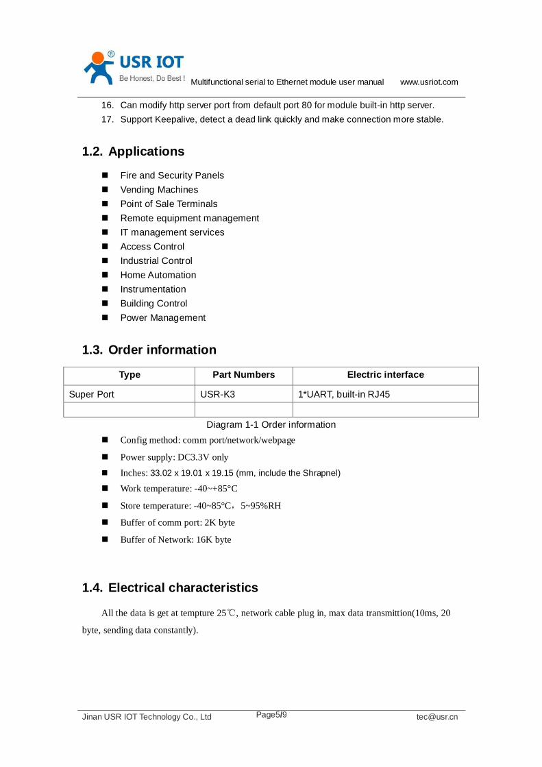
1.3. Order information
Type Part Numbers Electric interface
Super Port USR-K3 1*UART, built-in RJ45
Diagram 1-1 Order information
Config method: comm port/network/webpage
Power supply: DC3.3V only
Inches: 33.02 x 19.01 x 19.15 (mm, include the Shrapnel)
Work temperature: -40~+85°C
Store temperature: -40~85°C,5~95%RH
Buffer of comm port: 2K byte
Buffer of Network: 16K byte
1.4. Electrical characteristics
All the data is get at tempture 25℃, network cable plug in, max data transmittion(10ms, 20
byte, sending data constantly).
Multifunctional serial to Ethernet module user manual www.usriot.com
Jinan USR IOT Technology Co., Ltd [email protected] Page6/9
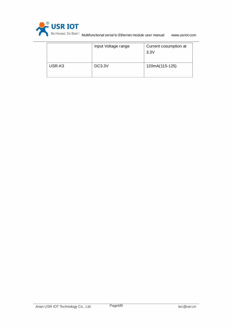
Input Voltage range Current cosumption at
3.3V
USR-K3 DC3.3V 120mA(115-125)

Multifunctional serial to Ethernet module user manual www.usriot.com
Jinan USR IOT Technology Co., Ltd [email protected] Page7/9
2. Module Test
If you have any question, please contact us the in the client support center:
http://h.usriot.com/index.php?c=frontTicket&m=sign
2.1. Hardware connection
The picture below is a serial device server of USR-K3. It have 1 UART to ethernet interafce.
Diagram 2-1 TCP232-410 with case
Power the eval board with DC5V adaptor(make sure you can supply at least 200mA current
at DC5V, USR-K3 only accept DC3.3V, but since we are using a eval board, DC5V will do)
Connect K3's RJ45 to PC directly with network cable(No need to distinguish cross or direct
connect cable), or connect the module and PC via switch or router and set the PC's ip address to
192.168.0.201(must be a format of 192.168.0.xxx), netmask 255.255.255.0.
Connect eval board's RS232 and PC's comm port together, with a standard male-female
extend cable(default no-cross-over cable).

Multifunctional serial to Ethernet module user manual www.usriot.com
Jinan USR IOT Technology Co., Ltd [email protected] Page8/9
Here is USR-K3's default net configuration,
IP address: 192.168.0.7
Subnet mask: 255.255.255.0
The default gateway: 192.168.0.1
2.2. Login
Open a browser, type and Login above IP address http://192.168.0.7, you will enter module's
setup web pages. There will be a windows login verify dialog.
User name and password are both “admin”, this can be modified after login into the system.
Default user name: admin
Default password: admin
After you login, you can see webpage as follow,
Diagram 2-2 webpage after login
Current Status: the module's name, current ip, firmware revision, and other status infomation
Local IP Config: the module's ip address, submask and gateway parameter
TTL1: the module's serial to ethernet parameter
Web to Serial: web to serial data transparent
Misc Config: some parameter such as user name and password parameter
Reboot: user can reboot/restart module from here
Multifunctional serial to Ethernet module user manual www.usriot.com
Jinan USR IOT Technology Co., Ltd [email protected] Page9/9
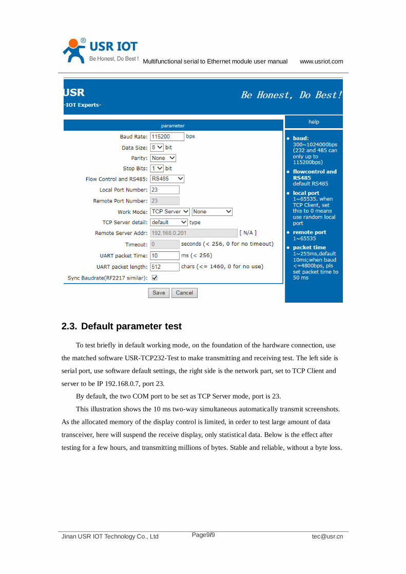
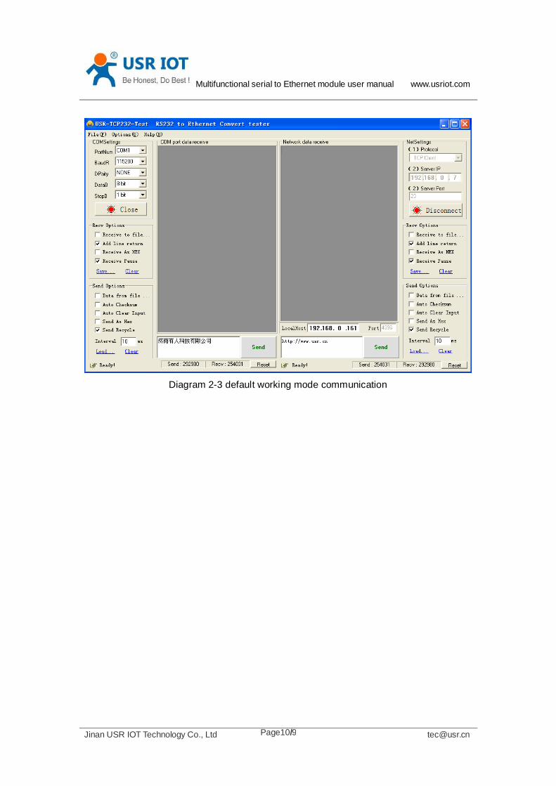
2.3. Default parameter test
To test briefly in default working mode, on the foundation of the hardware connection, use
the matched software USR-TCP232-Test to make transmitting and receiving test. The left side is
serial port, use software default settings, the right side is the network part, set to TCP Client and
server to be IP 192.168.0.7, port 23.
By default, the two COM port to be set as TCP Server mode, port is 23.
This illustration shows the 10 ms two-way simultaneous automatically transmit screenshots.
As the allocated memory of the display control is limited, in order to test large amount of data
transceiver, here will suspend the receive display, only statistical data. Below is the effect after
testing for a few hours, and transmitting millions of bytes. Stable and reliable, without a byte loss.
Multifunctional serial to Ethernet module user manual www.usriot.com
Jinan USR IOT Technology Co., Ltd [email protected] Page10/9
Diagram 2-3 default working mode communication
Multifunctional serial to Ethernet module user manual www.usriot.com
Jinan USR IOT Technology Co., Ltd [email protected] Page11/9
3. Work mode
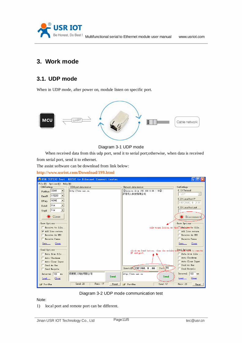
3.1. UDP mode
When in UDP mode, after power on, module listen on specific port.
Diagram 3-1 UDP mode
When received data from this udp port, send it to serial port;otherwise, when data is received
from serial port, send it to ethernet.
The assist software can be download from link below:
http://www.usriot.com/Download/199.html
Diagram 3-2 UDP mode communication test
Note:
1) local port and remote port can be different.
Multifunctional serial to Ethernet module user manual www.usriot.com
Jinan USR IOT Technology Co., Ltd [email protected] Page12/9
2) Max UDP send length(ethernet to serial) is 1472 bytes. If you want to send more than 1472
Bytes, please div it into shorter packet.
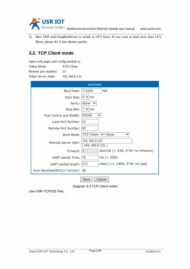
3.2. TCP Client mode
Open web pages and config module to
Telent Mode: TCP Client
Remote port number: 23
Telnet Server Addr: 192.168.0.131
Diagram 3-3 TCP Client mode
Use USR-TCP232-Test,

Multifunctional serial to Ethernet module user manual www.usriot.com
Jinan USR IOT Technology Co., Ltd [email protected] Page13/9
Diagram 3-4 TCP Client communication test
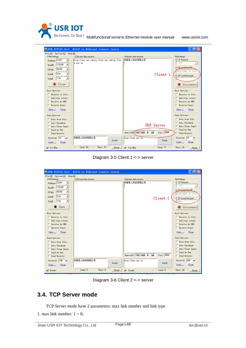
3.3. UDP Server mode
Like the socket UDP server in pc API. Many to one data transfer supported, the data
from uart part will be transformed to the last UDP packet’s address.
Here show 2 UDP client communicate with server, server send data to the last client
communicates with it.
Multifunctional serial to Ethernet module user manual www.usriot.com
Jinan USR IOT Technology Co., Ltd [email protected] Page14/9
Diagram 3-5 Client 1 <-> server
Diagram 3-6 Client 2 <-> server
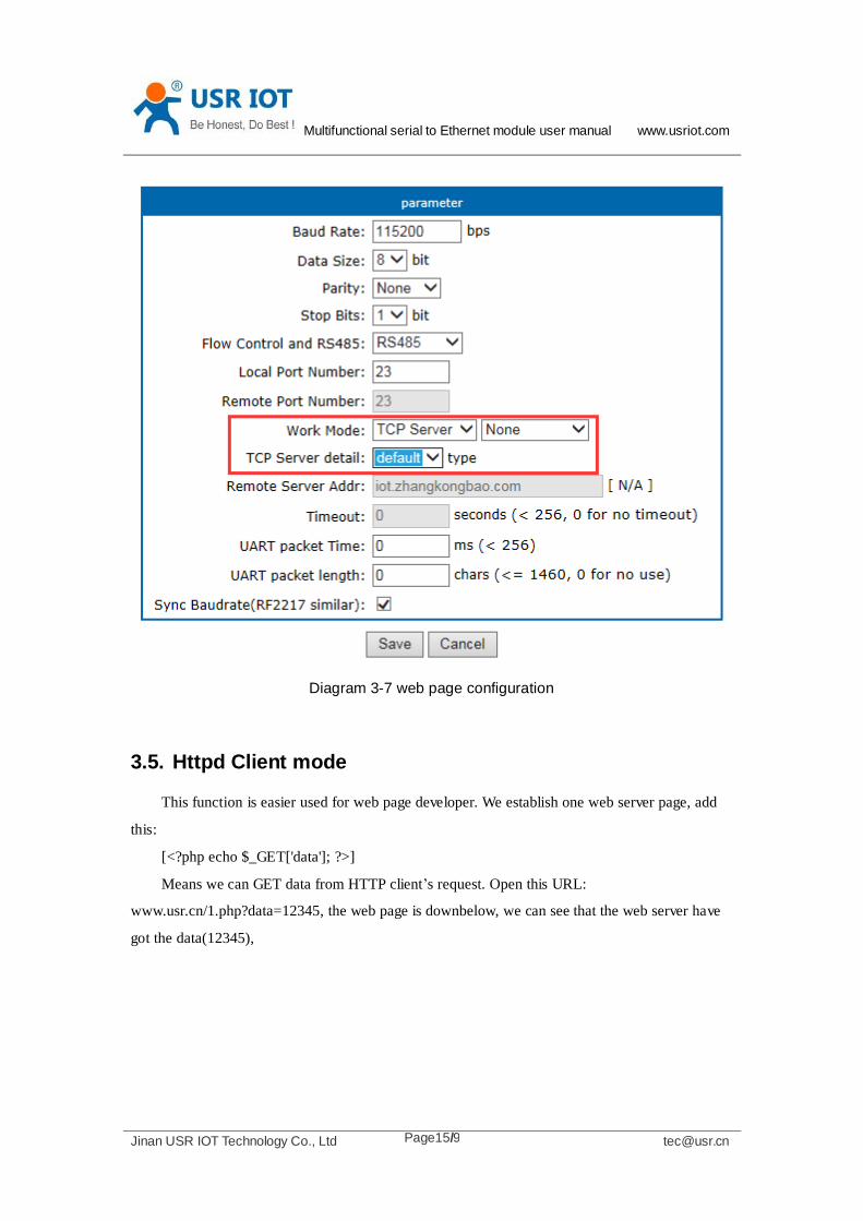
3.4. TCP Server mode
TCP Server mode have 2 parameters: max link number and link type
1. max link number: 1 ~ 8;
Multifunctional serial to Ethernet module user manual www.usriot.com
Jinan USR IOT Technology Co., Ltd [email protected] Page15/9
Diagram 3-7 web page configuration
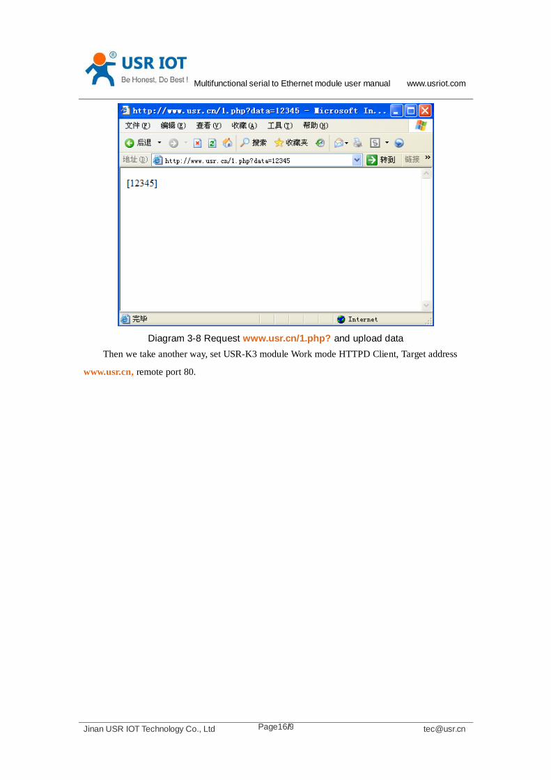
3.5. Httpd Client mode
This function is easier used for web page developer. We establish one web server page, add
this:
[<?php echo $_GET['data']; ?>]
Means we can GET data from HTTP client’s request. Open this URL:
www.usr.cn/1.php?data=12345, the web page is downbelow, we can see that the web server have
got the data(12345),
Multifunctional serial to Ethernet module user manual www.usriot.com
Jinan USR IOT Technology Co., Ltd [email protected] Page16/9
Diagram 3-8 Request www.usr.cn/1.php? and upload data
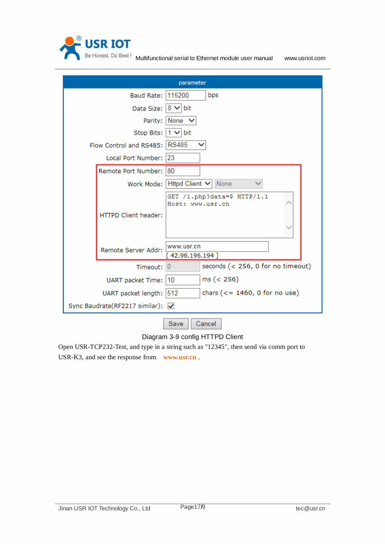
Then we take another way, set USR-K3 module Work mode HTTPD Client, Target address
www.usr.cn, remote port 80.
Multifunctional serial to Ethernet module user manual www.usriot.com
Jinan USR IOT Technology Co., Ltd [email protected] Page17/9
Diagram 3-9 config HTTPD Client
Open USR-TCP232-Test, and type in a string such as "12345", then send via comm port to
USR-K3, and see the response from www.usr.cn .

Multifunctional serial to Ethernet module user manual www.usriot.com
Jinan USR IOT Technology Co., Ltd [email protected] Page18/9
Diagram 3-10 module act as HTTPD Client
In the response, all the data returned, but the http header from server will be returned, too.
the user may need to parse this to get your data.
4. Hardware
About the new PCB libraries file, we can download it from website
http://www.usriot.com/Download/221.html .
Multifunctional serial to Ethernet module user manual www.usriot.com
Jinan USR IOT Technology Co., Ltd [email protected] Page19/9
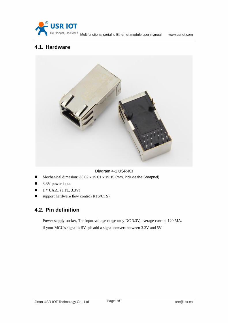
4.1. Hardware
Diagram 4-1 USR-K3
Mechanical dimesion: 33.02 x 19.01 x 19.15 (mm, include the Shrapnel)
3.3V power input
1 * UART (TTL, 3.3V)
support hardware flow control(RTS/CTS)
4.2. Pin definition
Power supply socket, The input voltage range only DC 3.3V, average current 120 MA.
if your MCU's signal is 5V, pls add a signal convert between 3.3V and 5V

Multifunctional serial to Ethernet module user manual www.usriot.com
Jinan USR IOT Technology Co., Ltd [email protected] Page20/9
Diagram 4-2 pin diagram of K3(left for top view, right for bottom view)
id name description
1 NC Unused, pls leave it to float
2 NC Unused, pls leave it to float
3 CTS Clear to send
4 RST Reset pin(give a constant 200ms low level make
module reset)
5 RTS Request to send(also muxed as RS485 enable tx pin,
enable it from software in )
6 Reload Unused, pls leave it to float
7 LED2 LED2, pls connect this pin to another LED2
8 RXD Data receive pin for comm port
9 TXD Data transmit pin for comm port
10 GND ground
11 3V3 DC3.3V(you must choose only one supply between
5V or 3.3V)
12 LED1 LED1, pls connect this pin to another LED1
13 LED2 LED2, pls connect this pin to another LED2
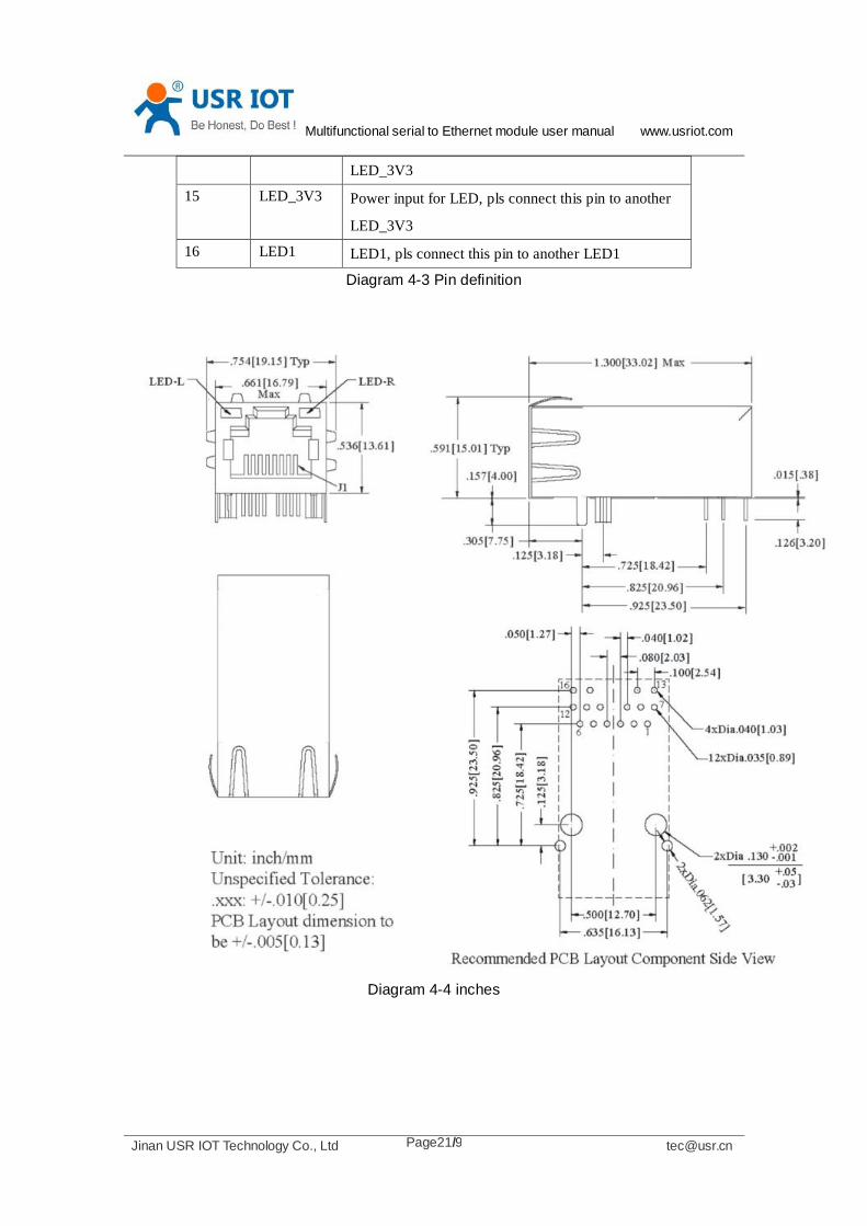
14 LED_3V3 Power input for LED, pls connect this pin to another
Multifunctional serial to Ethernet module user manual www.usriot.com
Jinan USR IOT Technology Co., Ltd [email protected] Page21/9
LED_3V3
15 LED_3V3 Power input for LED, pls connect this pin to another
LED_3V3
16 LED1 LED1, pls connect this pin to another LED1
Diagram 4-3 Pin definition
Diagram 4-4 inches
Multifunctional serial to Ethernet module user manual www.usriot.com
Jinan USR IOT Technology Co., Ltd [email protected] Page22/9
4.3. Connection diagram
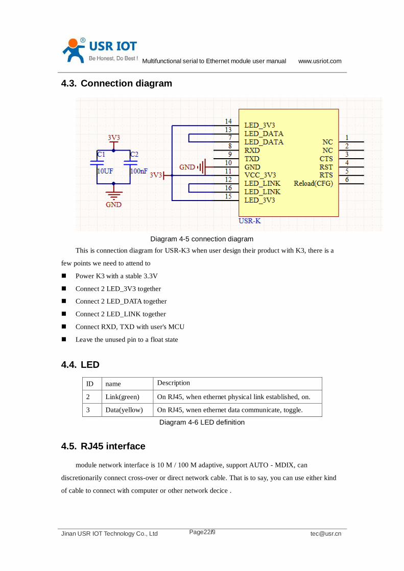
Diagram 4-5 connection diagram
This is connection diagram for USR-K3 when user design their product with K3, there is a
few points we need to attend to
Power K3 with a stable 3.3V
Connect 2 LED_3V3 together
Connect 2 LED_DATA together
Connect 2 LED_LINK together
Connect RXD, TXD with user's MCU
Leave the unused pin to a float state
4.4. LED
ID name Description
2 Link(green) On RJ45, when ethernet physical link established, on.
3 Data(yellow) On RJ45, wnen ethernet data communicate, toggle.
Diagram 4-6 LED definition
4.5. RJ45 interface
module network interface is 10 M / 100 M adaptive, support AUTO - MDIX, can
discretionarily connect cross-over or direct network cable. That is to say, you can use either kind
of cable to connect with computer or other network decice .
Multifunctional serial to Ethernet module user manual www.usriot.com
Jinan USR IOT Technology Co., Ltd [email protected] Page23/9
5. Paramters configuration
5.1. Web page
Usually, this module is configured through web pages.
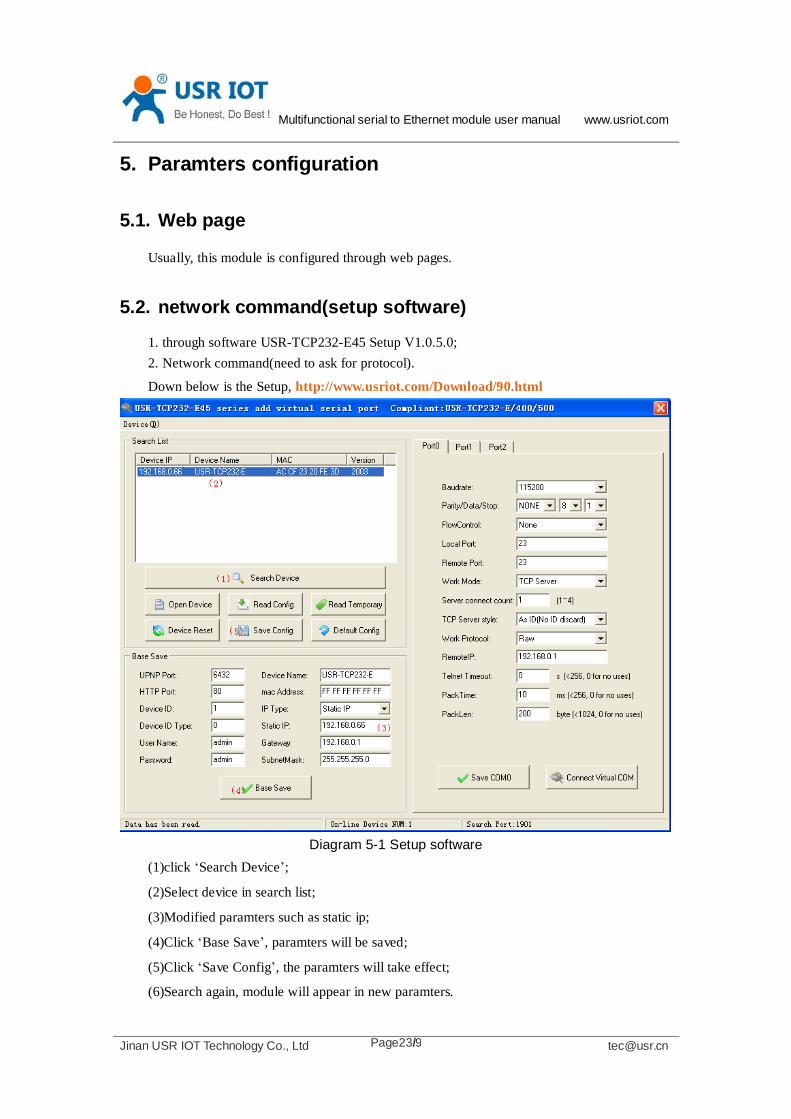
5.2. network command(setup software)
1. through software USR-TCP232-E45 Setup V1.0.5.0;
2. Network command(need to ask for protocol).
Down below is the Setup, http://www.usriot.com/Download/90.html
Diagram 5-1 Setup software
(1)click ‘Search Device’;
(2)Select device in search list;
(3)Modified paramters such as static ip;
(4)Click ‘Base Save’, paramters will be saved;
(5)Click ‘Save Config’, the paramters will take effect;
(6)Search again, module will appear in new paramters.
Multifunctional serial to Ethernet module user manual www.usriot.com
Jinan USR IOT Technology Co., Ltd [email protected] Page24/9
Note.
After modified paramters, need first ‘Base Save’ or ‘Save COMx’, then ‘Save Config’.
If not, the paramters will only be saved, but not take effect.
6. Specific functions
6.1. ModbusRTU to ModbusTCP
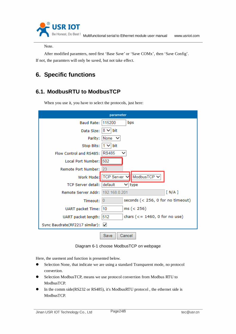
When you use it, you have to select the protocols, just here:
Diagram 6-1 choose ModbusTCP on webpage
Here, the usement and function is presented below.
Selection None, that indicate we are using a standard Transparent mode, no protocol
convertion.
Selection ModbusTCP, means we use protocol convertion from Modbus RTU to
ModbusTCP.
In the comm side(RS232 or RS485), it's ModbusRTU protocol , the ethernet side is
ModbusTCP.
Multifunctional serial to Ethernet module user manual www.usriot.com
Jinan USR IOT Technology Co., Ltd [email protected] Page25/9
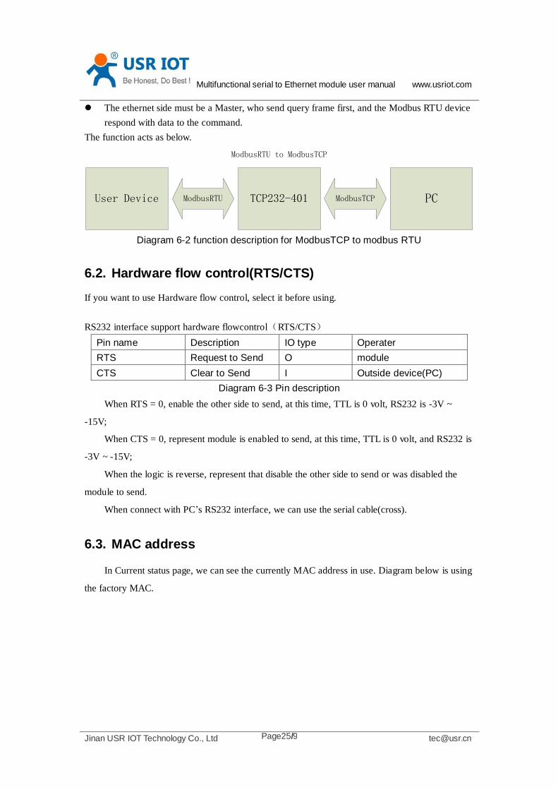
The ethernet side must be a Master, who send query frame first, and the Modbus RTU device
respond with data to the command.
The function acts as below.
PCTCP232-401User Device
ModbusRTU to ModbusTCP
ModbusRTU ModbusTCP
Diagram 6-2 function description for ModbusTCP to modbus RTU
6.2. Hardware flow control(RTS/CTS)
If you want to use Hardware flow control, select it before using.
RS232 interface support hardware flowcontrol(RTS/CTS)
Pin name Description IO type Operater
RTS Request to Send O module
CTS Clear to Send I Outside device(PC)
Diagram 6-3 Pin description
When RTS = 0, enable the other side to send, at this time, TTL is 0 volt, RS232 is -3V ~
-15V;
When CTS = 0, represent module is enabled to send, at this time, TTL is 0 volt, and RS232 is
-3V ~ -15V;
When the logic is reverse, represent that disable the other side to send or was disabled the
module to send.
When connect with PC’s RS232 interface, we can use the serial cable(cross).
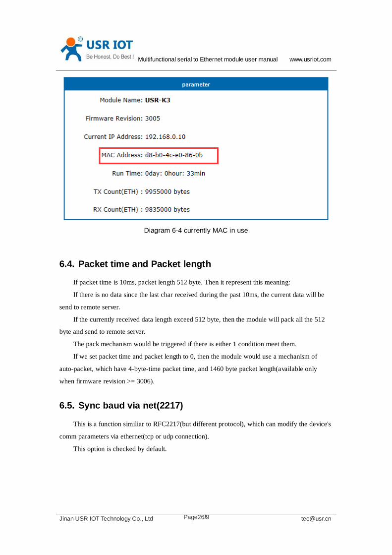
6.3. MAC address
In Current status page, we can see the currently MAC address in use. Diagram below is using
the factory MAC.
Multifunctional serial to Ethernet module user manual www.usriot.com
Jinan USR IOT Technology Co., Ltd [email protected] Page26/9
Diagram 6-4 currently MAC in use
6.4. Packet time and Packet length
If packet time is 10ms, packet length 512 byte. Then it represent this meaning:
If there is no data since the last char received during the past 10ms, the current data will be
send to remote server.
If the currently received data length exceed 512 byte, then the module will pack all the 512
byte and send to remote server.
The pack mechanism would be triggered if there is either 1 condition meet them.
If we set packet time and packet length to 0, then the module would use a mechanism of
auto-packet, which have 4-byte-time packet time, and 1460 byte packet length(available only
when firmware revision >= 3006).
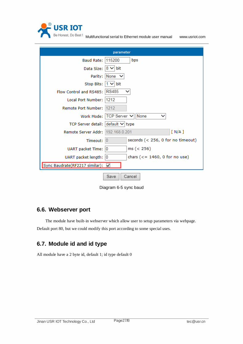
6.5. Sync baud via net(2217)
This is a function similiar to RFC2217(but different protocol), which can modify the device's
comm parameters via ethernet(tcp or udp connection).
This option is checked by default.
Multifunctional serial to Ethernet module user manual www.usriot.com
Jinan USR IOT Technology Co., Ltd [email protected] Page27/9
Diagram 6-5 sync baud
6.6. Webserver port
The module have built-in webserver which allow user to setup parameters via webpage.
Default port 80, but we could modify this port according to some special uses.
6.7. Module id and id type
All module have a 2 byte id, default 1; id type default 0

Multifunctional serial to Ethernet module user manual www.usriot.com
Jinan USR IOT Technology Co., Ltd [email protected] Page28/9
Diagram 6-6 module id and id type
The id type have a mean as below.
ID type description
0(by default) No use
1 When module act as client(tcp or udp), after it connect to server, send 4 byte
immediately(2 byte Id + 2 byte Id-Complement, 00 01 FF FE by default);
This can be used for USR-D2D service
2 add 4-byte before each frame send to server
3 Both 1 and 2
6.8. Device name
User can modify this name, 15 chars max.
Multifunctional serial to Ethernet module user manual www.usriot.com
Jinan USR IOT Technology Co., Ltd [email protected] Page29/9
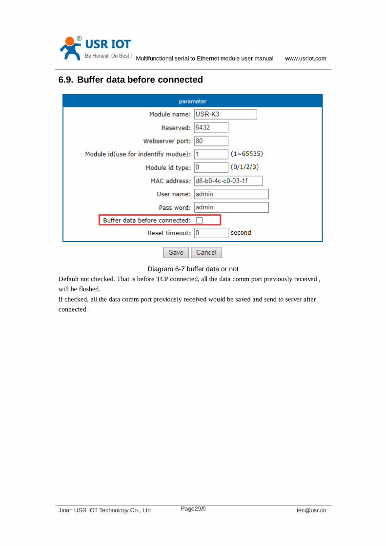
6.9. Buffer data before connected
Diagram 6-7 buffer data or not
Default not checked. That is before TCP connected, all the data comm port previously received ,
will be flushed.
If checked, all the data comm port previously received would be saved and send to server after
connected.

Multifunctional serial to Ethernet module user manual www.usriot.com
Jinan USR IOT Technology Co., Ltd [email protected] Page30/9
6.10. Reset timeout
Diagram 6-8 Reset timeout
Default 0, unit is second. When this value between 0~60, the reset timeout function would be no
use.
When this value is higher than 60, the module will restart if there is no data received during this
time.
6.11. Local IP config
There is Static IP and DHCP, Static IP by default.

Multifunctional serial to Ethernet module user manual www.usriot.com
Jinan USR IOT Technology Co., Ltd [email protected] Page31/9
Diagram 6-9 Local IP config
6.11.1. Static IP
Type in the ip address you want to config, such as 192.168.0.10 (192.168.0.7 by default);
Submask usually 255.255.255.0
Gateway usually 192.168.0.1 (your router's ip address)
6.11.2. DHCP
Choose DHCP and save, then reset to take effect. The module will get it's ip address in
5-10seconds, after that you can search for it in the setup software.
6.12. DNS
The module can visit both ip or remote domain name, user can type in the domain name in
the IP box. The domain name max length will be 30 chars.
Diagram 6-10 domain name or IP

Multifunctional serial to Ethernet module user manual www.usriot.com
Jinan USR IOT Technology Co., Ltd [email protected] Page32/9
6.13. Comm param
The baud ranges from 600bps to 1024kbps, user can define this to any value.
For the serial device server of RS232 interface, such as TCP232-410, the RS232 interface can
only up to 115200bps.
Databit range 5, 6, 7, 8;
Paritybit range None, Odd, Even, Mark, Space
Stopbit range 1, 2
1.1. Username and password
Default both "admin", max 5 chars.
6.14. Firmware revision
USR-K3 的固件版本从 V3000 开始递增。版本可以在网页的左上方看到,或者是在搜索
软件上看到。
Diagram 6-11 Firmware revision
6.15. RS485
The module's RTS pin, is configured as 485_EN pin, by default.
If you want to extend a RS485 interaface for TCP232-E or TCP232-ED2, you can connect
this RTS pin to the 485 IC's enable pin.
6.16. Firmupdate
Use search and config software to update firmware,
there is a few point need be be attention
Asking for the firmware from us

Multifunctional serial to Ethernet module user manual www.usriot.com
Jinan USR IOT Technology Co., Ltd [email protected] Page33/9
only one module for one time, can not cross network segment.
You must connect module directly with your PC with a single net cable, and set your PC with
a static IP in same segment with module
1. Search and select one module
Diagram 6-12 search and select
2. ‘Device’ -> firmware update
Multifunctional serial to Ethernet module user manual www.usriot.com
Jinan USR IOT Technology Co., Ltd [email protected] Page34/9
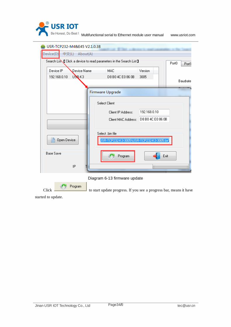
Diagram 6-13 firmware update
Click to start update progress. If you see a progress bar, means it have
started to update.
Multifunctional serial to Ethernet module user manual www.usriot.com
Jinan USR IOT Technology Co., Ltd [email protected] Page35/9
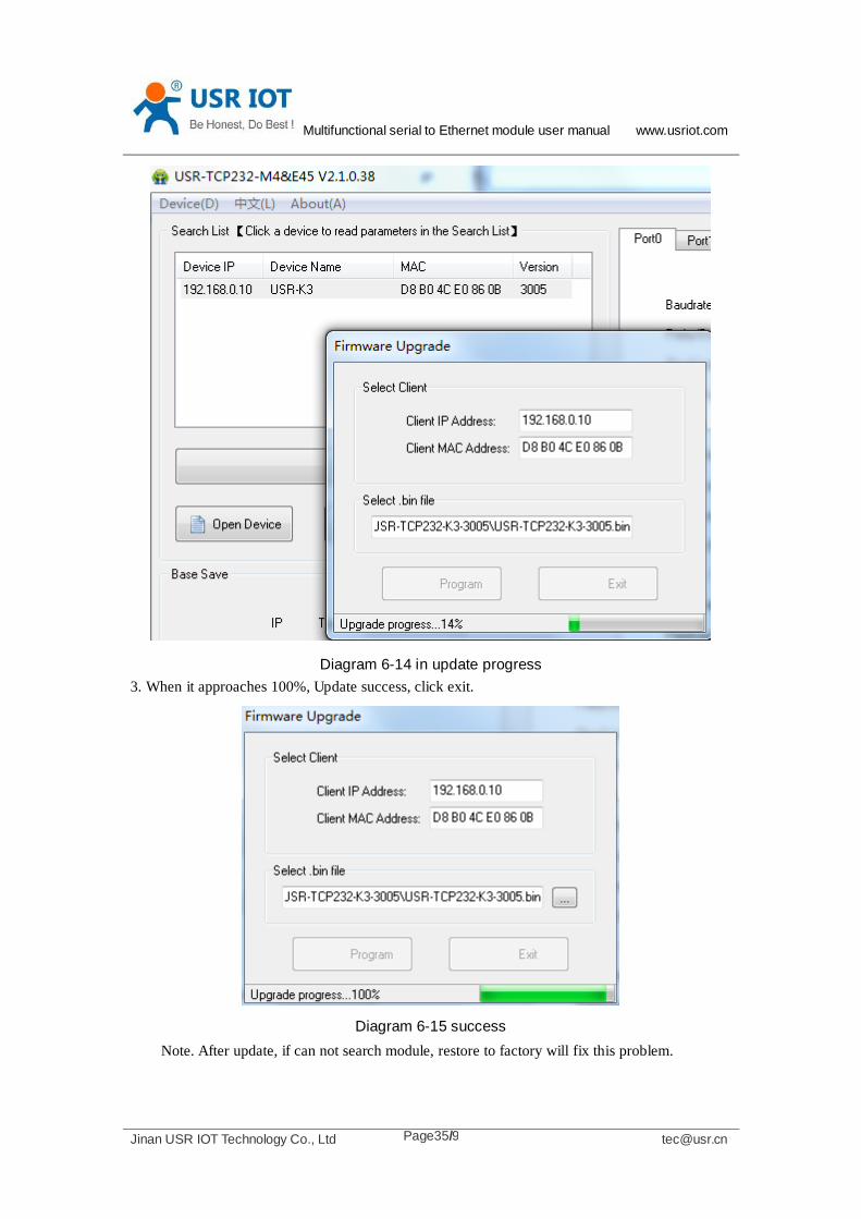
Diagram 6-14 in update progress
3. When it approaches 100%, Update success, click exit.
Diagram 6-15 success
Note. After update, if can not search module, restore to factory will fix this problem.

Multifunctional serial to Ethernet module user manual www.usriot.com
Jinan USR IOT Technology Co., Ltd [email protected] Page36/9
6.17. Common questions
6.17.1. Work across network segment
If your TCP232 device’s IP is 192.168.0.7, and remote PC’s IP is 192.168.1.7, we need to
config.
Subnet mask of TCP232 device, PC, and router to 255.255.0.0, if not ,the TCP232 module
will not communicate normally.
6.17.2. Ping is OK but can not open web pages
Some possible causes
1. Module is set a static ip and conflicts with another ethernet device.
2. Cross network and false subnet mask .
3. HTTP server port is modified(default 80).
Solutions:
1. Set another static or use DHCP.
2. Set correct subnet mask.
3. Set this port to 80 or open web page with correct port.
6.17.3. After firm update, can not open web page
Reload this module back to factory settings.
6.17.4. When connection established, server received serval chars
Possible causes.
1) Module id type is not 0.
Solutions.
1) Module id type set 0.
6.17.5. Every serval seconds, module reconnect
Maybe there is a network device which is same ip to module, pls check if ip conflict.
Multifunctional serial to Ethernet module user manual www.usriot.com
Jinan USR IOT Technology Co., Ltd [email protected] Page37/9
7. Contact us
Company: Jinan USR IOT Technology Co., Ltd
Address: Floor 11,Building1,No.1166 Xinluo Street,Gaoxin Distric,Jinan,Shandong,250101
China
Tel: 86-531-55507297 86-531-88826739-803
Web: http://www.usriot.com/
Skype: lisausr
Support: http://h.usriot.com/index.php?c=frontTicket&m=sign
Multifunctional serial to Ethernet module user manual www.usriot.com
Jinan USR IOT Technology Co., Ltd [email protected] Page38/9
8. Modified history
1) V1.0 .1 doc established by Huibin Li
2) V1.0.3 correct website link and picture mistake
3) V1.0.5 add support center website
4) V1.0.6 update pin definition picture for K3
5) V1.0.7 add reset timeout and buffer data
6) V1.0.8 new address