Embed Size (px)
Citation preview
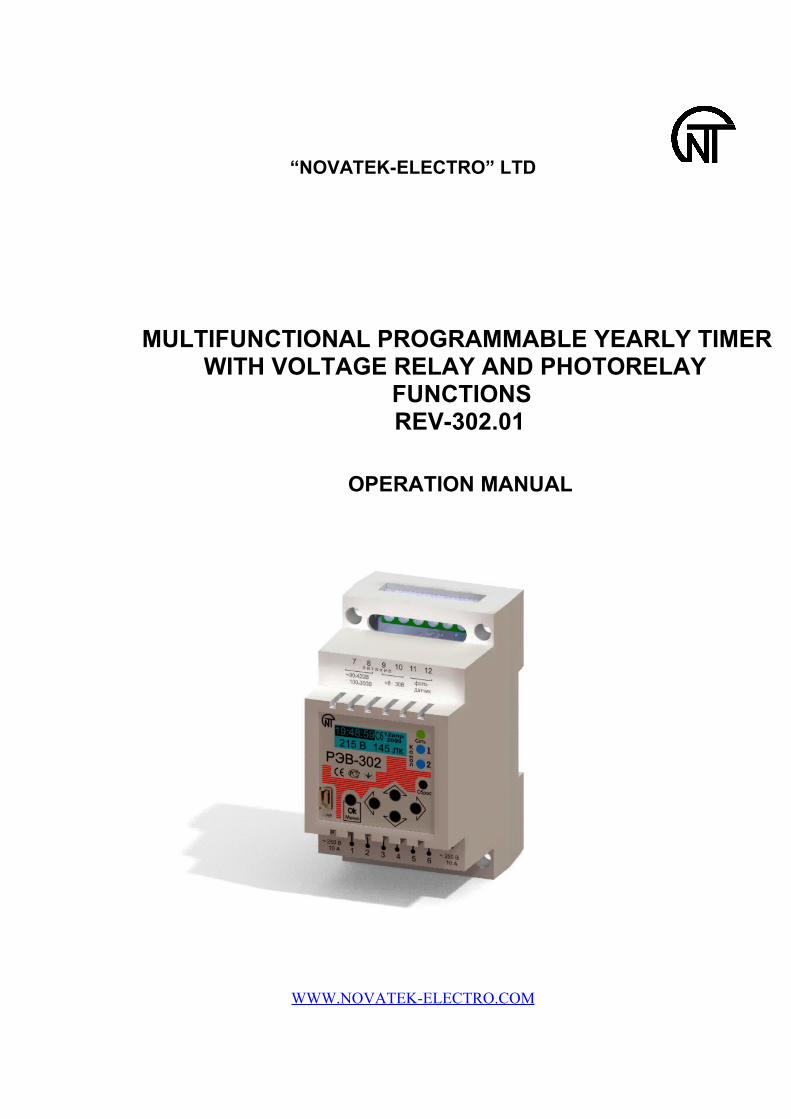
“NOVATEK-ELECTRO” LTD
MULTIFUNCTIONAL PROGRAMMABLE YEARLY TIMER WITH VOLTAGE RELAY AND PHOTORELAY
FUNCTIONS REV-302.01
OPERATION MANUAL
WWW.NOVATEK-ELECTRO.COM

This manual has been developed as introduction to the design, operating principle, working procedures and settings of the multifunctional REV-302.01 relay.
1 DESCRIPTION AND OPERATION
The REV-302.01 multi-functional relay is a microprocessor-based programmable device designed to energize/de-energize one or two loads within user-set time intervals based on the circuit voltage and the external photo sensor luminance.
1.1 GENERAL
The REV-302.01specific features: 2 switching contact groups of 10A rated current at 250V switching AC voltage. Power supply: 220V/50Hz AC or 24V DC. Time relay, voltage relay and photo relay combined or independent operation. Flexible contact switching control between the voltage relay, the photo relay and the time
relay. 8 independent control programs and capability of swift transfer between them for each
contact group. Capability to control both contact groups with a single program. 10 year calendar standalone power supply. Daily, weekly, monthly, and yearly time relay program. Independent events settings for each program. Planned event clock accuracy of up to 1 second. Programmable holiday and day off list option. Specific timer listing execution for days off and holidays. Common internal memory for 5000 independent events distributed between all programs
for day/week/month/year mode depending on the mode selected. Option of program cyclic repeat within a specified time interval. Automatic summer/winter time conversion. Pulse time relay function (periodic, calendar independent contacts close/open). Function of plain contacts closure within a specified delay after energization. Contacts close/open based on minimum and maximum circuit voltage. Temporary delay for the after-energization relay start. Separate time delays for the voltage relay and the photo relay actions (for setting the
reclosing time, etc.) External photo sensor. LCD graphical display Status indication for each contact group. PC connection USB input. Russian language interface. Control via 5 keys on the front panel. Loading preset control programs via USB with use of supplemental software. Password protection option for the settings menu. General reset key on the front panel.
2
1.2 TECHNICAL BRIEF
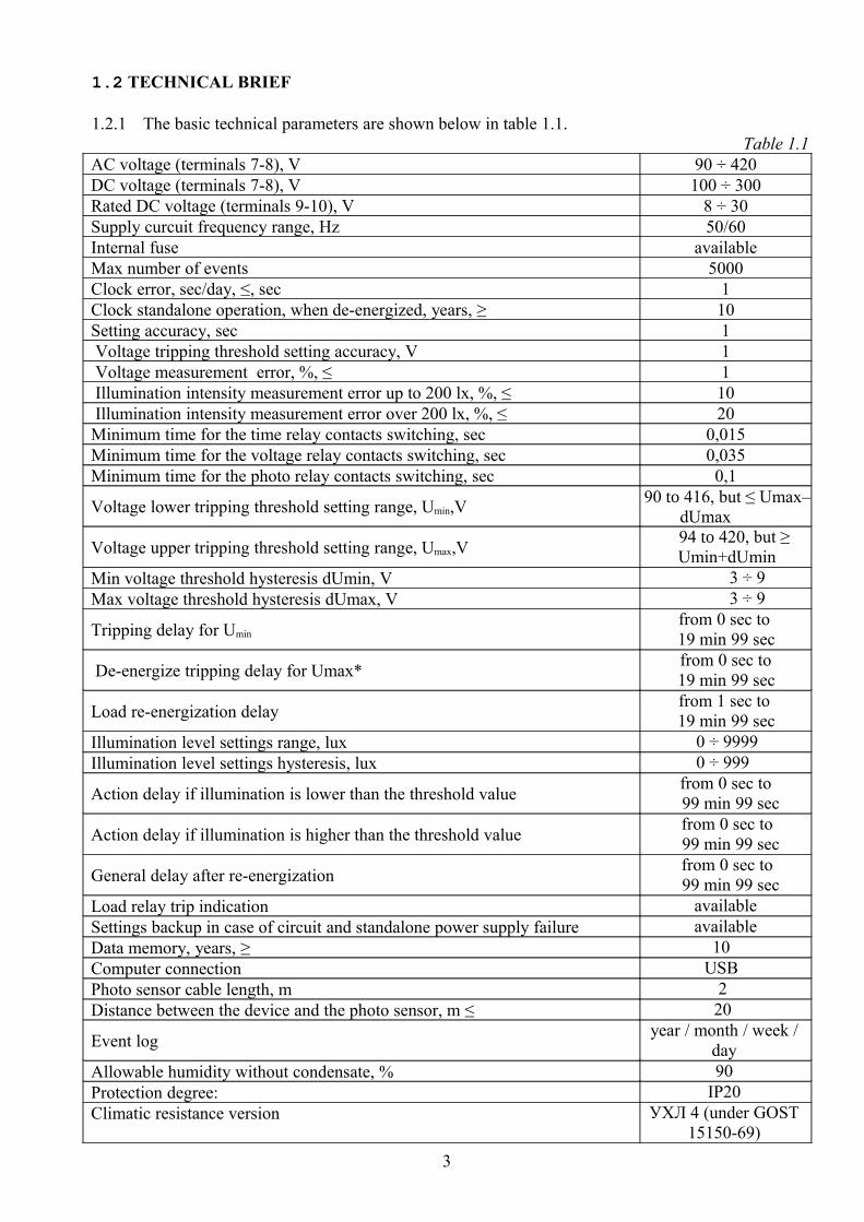
1.2.1 The basic technical parameters are shown below in table 1.1.Table 1.1
AC voltage (terminals 7-8), V 90 ÷ 420DC voltage (terminals 7-8), V 100 ÷ 300Rated DC voltage (terminals 9-10), V 8 ÷ 30Supply curcuit frequency range, Hz 50/60Internal fuse availableMax number of events 5000Clock error, sec/day, ≤, sec 1Clock standalone operation, when de-energized, years, ≥ 10Setting accuracy, sec 1 Voltage tripping threshold setting accuracy, V 1 Voltage measurement error, %, ≤ 1 Illumination intensity measurement error up to 200 lx, %, ≤ 10 Illumination intensity measurement error over 200 lx, %, ≤ 20Minimum time for the time relay contacts switching, sec 0,015Minimum time for the voltage relay contacts switching, sec 0,035Minimum time for the photo relay contacts switching, sec 0,1
Voltage lower tripping threshold setting range, Umin,V 90 to 416, but ≤ Umax–dUmax94Voltage upper tripping threshold setting range, Umax,V to 420, but ≥ Umin+dUmin
Min voltage threshold hysteresis dUmin, V 3 ÷ 9Max voltage threshold hysteresis dUmax, V 3 ÷ 9
Tripping delay for Umin from 0 sec to
19 min 99 sec
De-energize tripping delay for Umax* from 0 sec to 19 min 99 sec
Load re-energization delay from 1 sec to 19 min 99 sec
Illumination level settings range, lux 0 ÷ 9999Illumination level settings hysteresis, lux 0 ÷ 999
Action delay if illumination is lower than the threshold value from 0 sec to 99 min 99 sec
Action delay if illumination is higher than the threshold value from 0 sec to 99 min 99 sec
General delay after re-energization from 0 sec to 99 min 99 sec
Load relay trip indication availableSettings backup in case of circuit and standalone power supply failure availableData memory, years, ≥ 10Computer connection USBPhoto sensor cable length, m 2Distance between the device and the photo sensor, m ≤ 20
Event log year / month / week / day
Allowable humidity without condensate, % 90Protection degree: ІР20Climatic resistance version УХЛ 4 (under GOST
15150-69)3
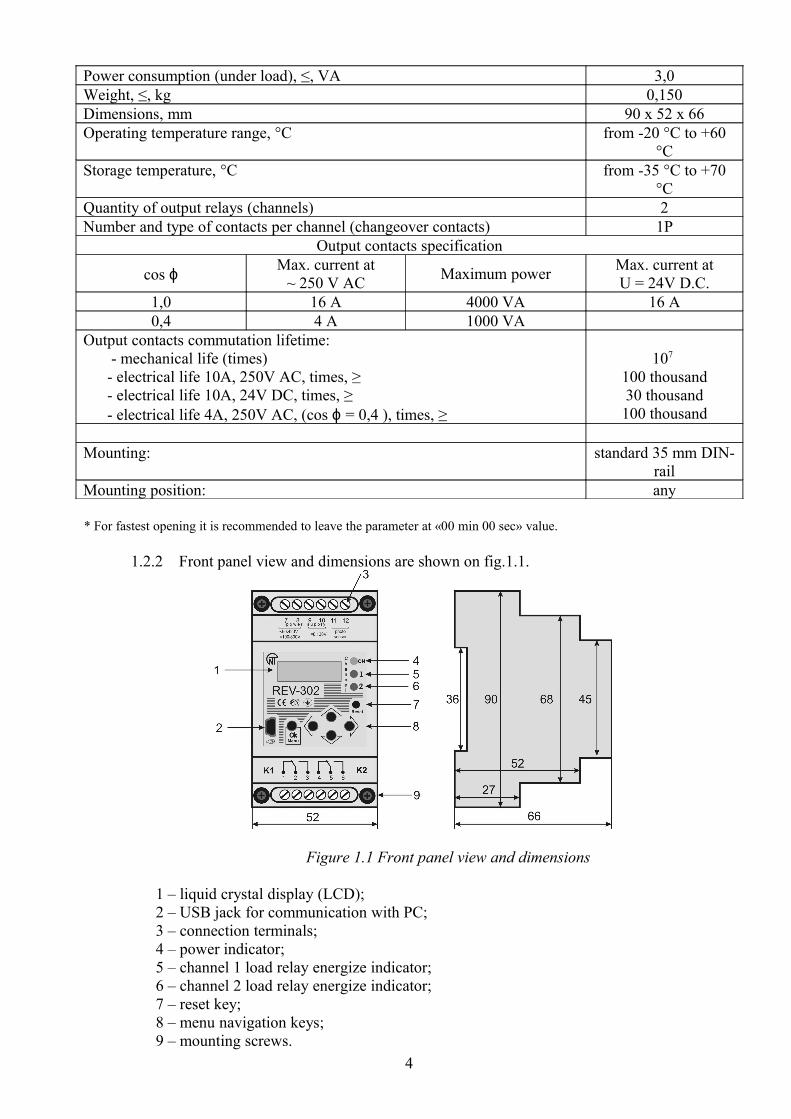
Power consumption (under load), ≤, VA 3,0Weight, ≤, kg 0,150Dimensions, mm 90 х 52 х 66Operating temperature range, °C from -20 °C to +60
°CStorage temperature, °C from -35 °C to +70
°CQuantity of output relays (channels) 2Number and type of contacts per channel (changeover contacts) 1P
Output contacts specification
сos ϕ Max. current at~ 250 V AC Maximum power Max. current at
U = 24V D.C.1,0 16 А 4000 VА 16 А0,4 4 A 1000 VА
Output contacts commutation lifetime: - mechanical life (times) - electrical life 10А, 250V AC, times, ≥ - electrical life 10А, 24V DC, times, ≥ - electrical life 4А, 250V AC, (сos ϕ = 0,4 ), times, ≥
107 100 thousand30 thousand100 thousand
Mounting: standard 35 mm DIN-rail
Mounting position: any
* For fastest opening it is recommended to leave the parameter at «00 min 00 sec» value.
1.2.2 Front panel view and dimensions are shown on fig.1.1.
Figure 1.1 Front panel view and dimensions
1 – liquid crystal display (LCD);2 – USB jack for communication with PC;3 – connection terminals;4 – power indicator;5 – channel 1 load relay energize indicator;6 – channel 2 load relay energize indicator;7 – reset key;8 – menu navigation keys;9 – mounting screws.
4

1.2.3 Power supply sources
REV-302.01 may be powered by a standard 220V/50Hz AC circuit (terminals 7-8) or by a 24V DC source (terminals 9-10). Only one power source can be connected at a time.
In order to provide for the standalone clock operation in case of power voltage loss and to backup the programmed settings a 3V CR2032 lithium battery is utilized. The battery has 10 year life period.
If after an external power failure the time setting drops, the battery has to be replaced. To replace a dead battery:
- make sure that REV-302.01 is disconnected from the AC power supply and the DC power supply (terminals 7-10, fig. 1.1);
- unscrew the mounting screws 9; - remove the upper cover; - remove the old battery; - install a new CR2032, 3V battery into the holder block; - re-install the upper cover and the screw position 9 screws back on; - power the device via AC or DC power supply; - set the correct time via settings menu. Attention! The user may replace the clock battery on his/her own only in devices with
expired warranty period. Otherwise, damaging the seal will cancel the manufacturer’s warranty.
1.2.4 Photo sensor
The photo sensor (figure 1.3) supplied in the REV-302.01 package consists of panel holder, photo receiver and twin cable to be connected to terminals 11-12. If necessary, the cable length can be extended to 20 m.
Figure 1.3 Photo sensor diagram and exterior
1 – photo sensor panel holder;2 – twin cable, 0,25 sq. mm. section3, 4 – the photo sensor contacts (connected to terminals 11-12);
5
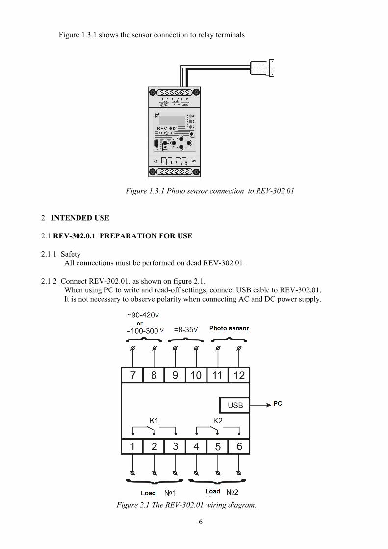
Figure 1.3.1 shows the sensor connection to relay terminals
Figure 1.3.1 Photo sensor connection to REV-302.01
2 INTENDED USE
2.1 REV-302.0.1 PREPARATION FOR USE
2.1.1 Safety All connections must be performed on dead REV-302.01.
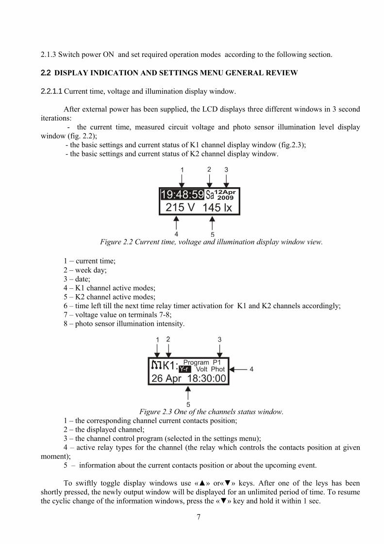
2.1.2 Connect REV-302.01. as shown on figure 2.1.When using PC to write and read-off settings, connect USB cable to REV-302.01. It is not necessary to observe polarity when connecting AC and DC power supply.
Figure 2.1 The REV-302.01 wiring diagram.
6
2.1.3 Switch power ON and set required operation modes according to the following section.
2.2 DISPLAY INDICATION AND SETTINGS MENU GENERAL REVIEW
2.2.1.1 Current time, voltage and illumination display window.
After external power has been supplied, the LCD displays three different windows in 3 second iterations:
- the current time, measured circuit voltage and photo sensor illumination level display window (fig. 2.2);
- the basic settings and current status of K1 channel display window (fig.2.3); - the basic settings and current status of K2 channel display window.
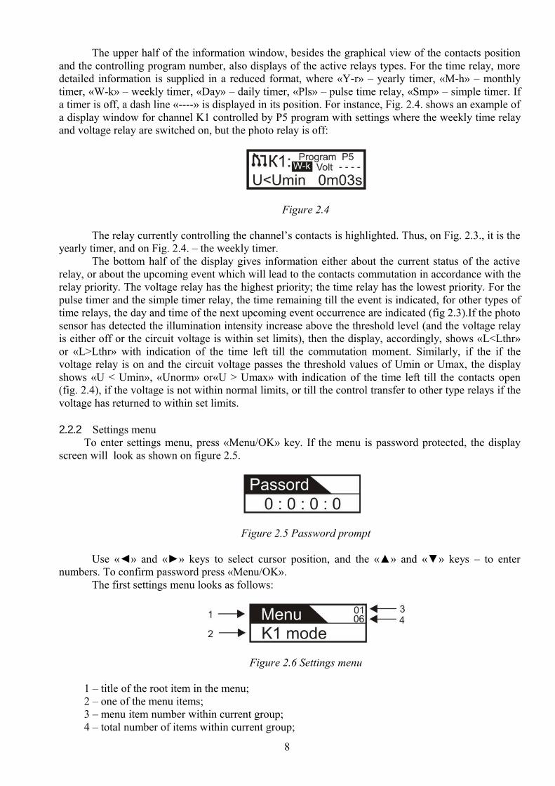
Figure 2.2 Current time, voltage and illumination display window view.
1 – current time;2 – week day;3 – date;4 – K1 channel active modes;5 – K2 channel active modes;6 – time left till the next time relay timer activation for K1 and K2 channels accordingly; 7 – voltage value on terminals 7-8;8 – photo sensor illumination intensity.
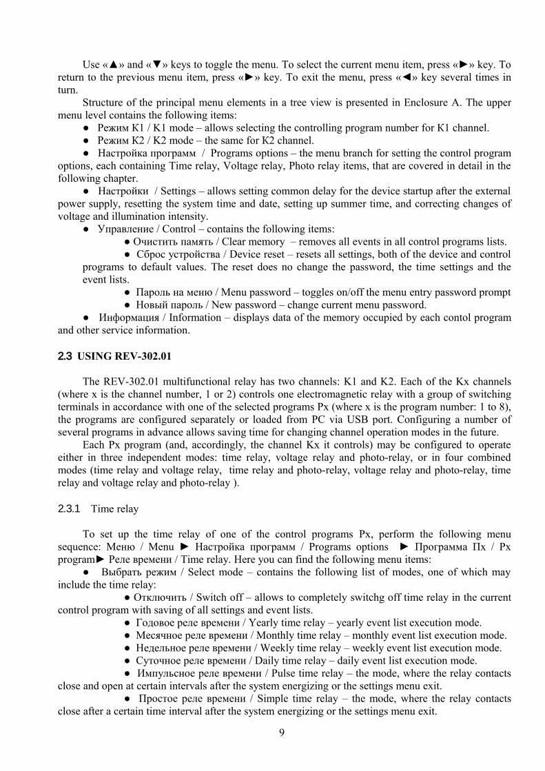
Figure 2.3 One of the channels status window.1 – the corresponding channel current contacts position;2 – the displayed channel;3 – the channel control program (selected in the settings menu);4 – active relay types for the channel (the relay which controls the contacts position at given
moment);5 – information about the current contacts position or about the upcoming event.
To swiftly toggle display windows use «▲» or«▼» keys. After one of the leys has been shortly pressed, the newly output window will be displayed for an unlimited period of time. To resume the cyclic change of the information windows, press the «▼» key and hold it within 1 sec.
7
The upper half of the information window, besides the graphical view of the contacts position and the controlling program number, also displays of the active relays types. For the time relay, more detailed information is supplied in a reduced format, where «Y-r» – yearly timer, «M-h» – monthly timer, «W-k» – weekly timer, «Day» – daily timer, «Pls» – pulse time relay, «Smp» – simple timer. If a timer is off, a dash line «----» is displayed in its position. For instance, Fig. 2.4. shows an example of a display window for channel K1 controlled by P5 program with settings where the weekly time relay and voltage relay are switched on, but the photo relay is off:
Figure 2.4
The relay currently controlling the channel’s contacts is highlighted. Thus, on Fig. 2.3., it is the yearly timer, and on Fig. 2.4. – the weekly timer.
The bottom half of the display gives information either about the current status of the active relay, or about the upcoming event which will lead to the contacts commutation in accordance with the relay priority. The voltage relay has the highest priority; the time relay has the lowest priority. For the pulse timer and the simple timer relay, the time remaining till the event is indicated, for other types of time relays, the day and time of the next upcoming event occurrence are indicated (fig 2.3).If the photo sensor has detected the illumination intensity increase above the threshold level (and the voltage relay is either off or the circuit voltage is within set limits), then the display, accordingly, shows «L<Lthr» or «L>Lthr» with indication of the time left till the commutation moment. Similarly, if the if the voltage relay is on and the circuit voltage passes the threshold values of Umin or Umax, the display shows «U < Umin», «Unorm» or«U > Umax» with indication of the time left till the contacts open (fig. 2.4), if the voltage is not within normal limits, or till the control transfer to other type relays if the voltage has returned to within set limits.
2.2.2 Settings menuTo enter settings menu, press «Menu/OK» key. If the menu is password protected, the display
screen will look as shown on figure 2.5.
Figure 2.5 Password prompt
Use «◄» and «►» keys to select cursor position, and the «▲» and «▼» keys – to enter numbers. To confirm password press «Menu/OK».
The first settings menu looks as follows:
Figure 2.6 Settings menu
1 – title of the root item in the menu;2 – one of the menu items;3 – menu item number within current group;4 – total number of items within current group;
8
Use «▲» and «▼» keys to toggle the menu. To select the current menu item, press «►» key. To return to the previous menu item, press «►» key. To exit the menu, press «◄» key several times in turn.
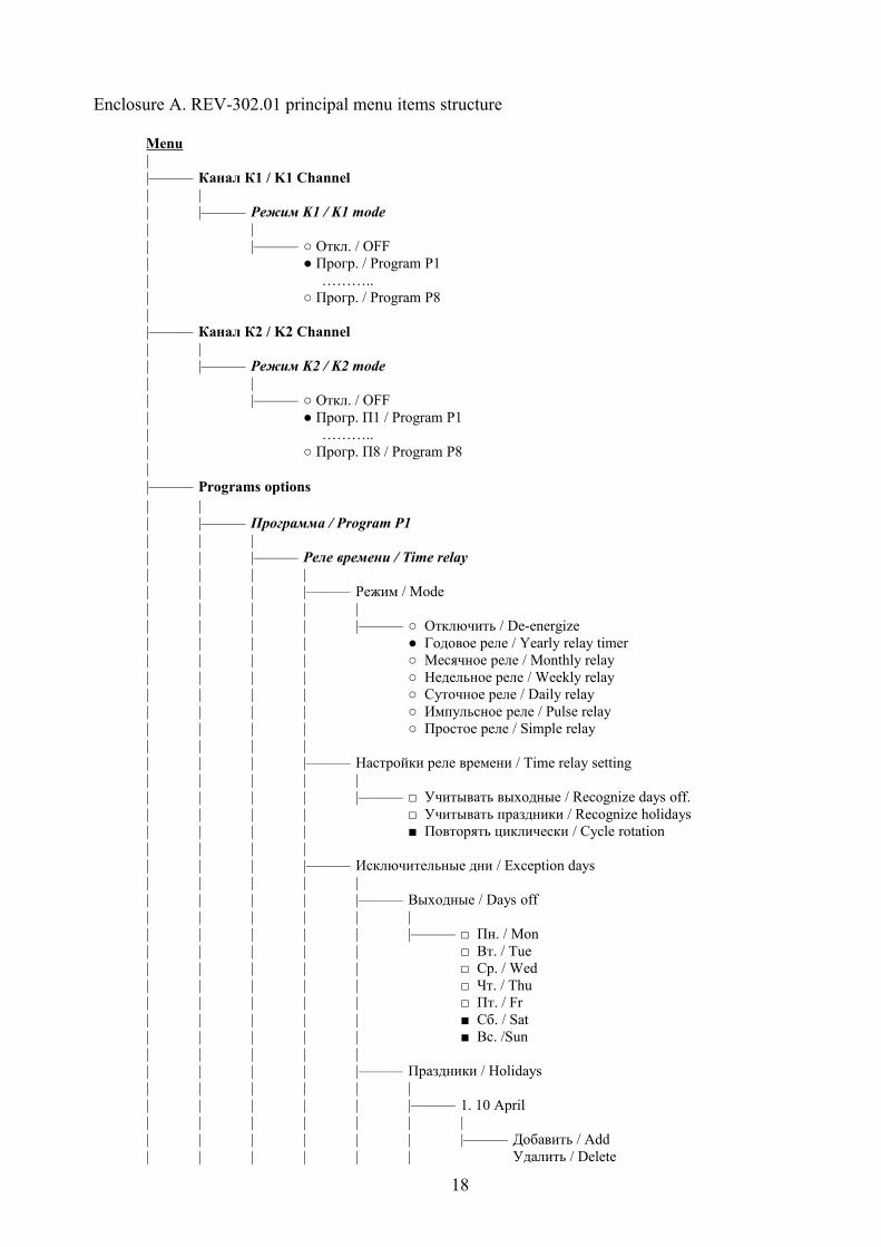
Structure of the principal menu elements in a tree view is presented in Enclosure A. The upper menu level contains the following items:
● Режим К1 / K1 mode – allows selecting the controlling program number for К1 channel.● Режим К2 / K2 mode – the same for К2 channel.● Настройка программ / Programs options – the menu branch for setting the control program
options, each containing Time relay, Voltage relay, Photo relay items, that are covered in detail in the following chapter.
● Настройки / Settings – allows setting common delay for the device startup after the external power supply, resetting the system time and date, setting up summer time, and correcting changes of voltage and illumination intensity.
● Управление / Control – contains the following items:● Очистить память / Clear memory – removes all events in all control programs lists.● Сброс устройства / Device reset – resets all settings, both of the device and control
programs to default values. The reset does no change the password, the time settings and the event lists.
● Пароль на меню / Menu password – toggles on/off the menu entry password prompt● Новый пароль / New password – change current menu password.
● Информация / Information – displays data of the memory occupied by each contol program and other service information.
2.3 USING REV-302.01
The REV-302.01 multifunctional relay has two channels: K1 and K2. Each of the Kx channels (where x is the channel number, 1 or 2) controls one electromagnetic relay with a group of switching terminals in accordance with one of the selected programs Px (where x is the program number: 1 to 8), the programs are configured separately or loaded from PC via USB port. Configuring a number of several programs in advance allows saving time for changing channel operation modes in the future.
Each Px program (and, accordingly, the channel Kx it controls) may be configured to operate either in three independent modes: time relay, voltage relay and photo-relay, or in four combined modes (time relay and voltage relay, time relay and photo-relay, voltage relay and photo-relay, time relay and voltage relay and photo-relay ).
2.3.1 Time relay
To set up the time relay of one of the control programs Px, perform the following menu sequence: Меню / Menu ► Настройка программ / Programs options ► Программа Пx / Px program► Реле времени / Time relay. Here you can find the following menu items:
● Выбрать режим / Select mode – contains the following list of modes, one of which may include the time relay:
● Отключить / Switch off – allows to completely switchg off time relay in the current control program with saving of all settings and event lists.
● Годовое реле времени / Yearly time relay – yearly event list execution mode.● Месячное реле времени / Monthly time relay – monthly event list execution mode.● Недельное реле времени / Weekly time relay – weekly event list execution mode.● Суточное реле времени / Daily time relay – daily event list execution mode.● Импульсное реле времени / Pulse time relay – the mode, where the relay contacts
close and open at certain intervals after the system energizing or the settings menu exit.● Простое реле времени / Simple time relay – the mode, where the relay contacts
close after a certain time interval after the system energizing or the settings menu exit.
9

● Настройки реле времени / Time relay settings – contains menu items that allow fine tuning the time relay:
● Учитывать выходные дни / Observe days off – the setting refers only to calendar type timers (i.e. yearly, monthly, weekly, and daily), and for days off foresees an exceptional event list in place of the currently set list for the specified timer.
● Учитывать праздники / Observe holidays – the setting refers only to calendar type timers, and for holidays (the holidays list is made up separately) foresees an exceptional event list in place of the currently set list for the specified timer.
● Повторять циклически / Cyclic rotation – indicates whether the mode event list will be executed once within a selected time interval, or will be repeated in cycles.
Please, see an example. Figure 2.7 presents a situation when P1 is set up as a daily timer in single-action mode ( i.e. the checkmark in the “Cyclic rotation” setting is not checked) with five events, each of them successively closing and opening the contacts of the controlled K2 channel. The upper graph shows the planned events in the list of daily events, the lower graph indicates the channel contacts physical status. REV-302.01 was started at the moment t1=4:00, and as within the interval between t0 and t1 any load activating events are not present, the channel contacts will close when the time for event#1 comes (t2=8:00). The last event in the day is event #5 (t6= 22:00) which leaves the contacts closed until either power supply is turned off or a new program is loaded.
Figure 2.8 shows the same example, but the daily relay is in cyclic mode (i.e. the “Cyclic rotation” checkmark is checked). Unlike figure 2.7 at the moment of REV-302.01 start (t1=4:00) the time relay take into account the last status the contacts had to be in before power-off. As there are no events between t0 and t1, the time relay relies onto the last day event #5 (t6= 22:00), according to which the contacts close. From the beginning of the next day the sequence of events is repeated.
Figure 2.7 Timer list single-action execution mode based on the daily timer example.
10
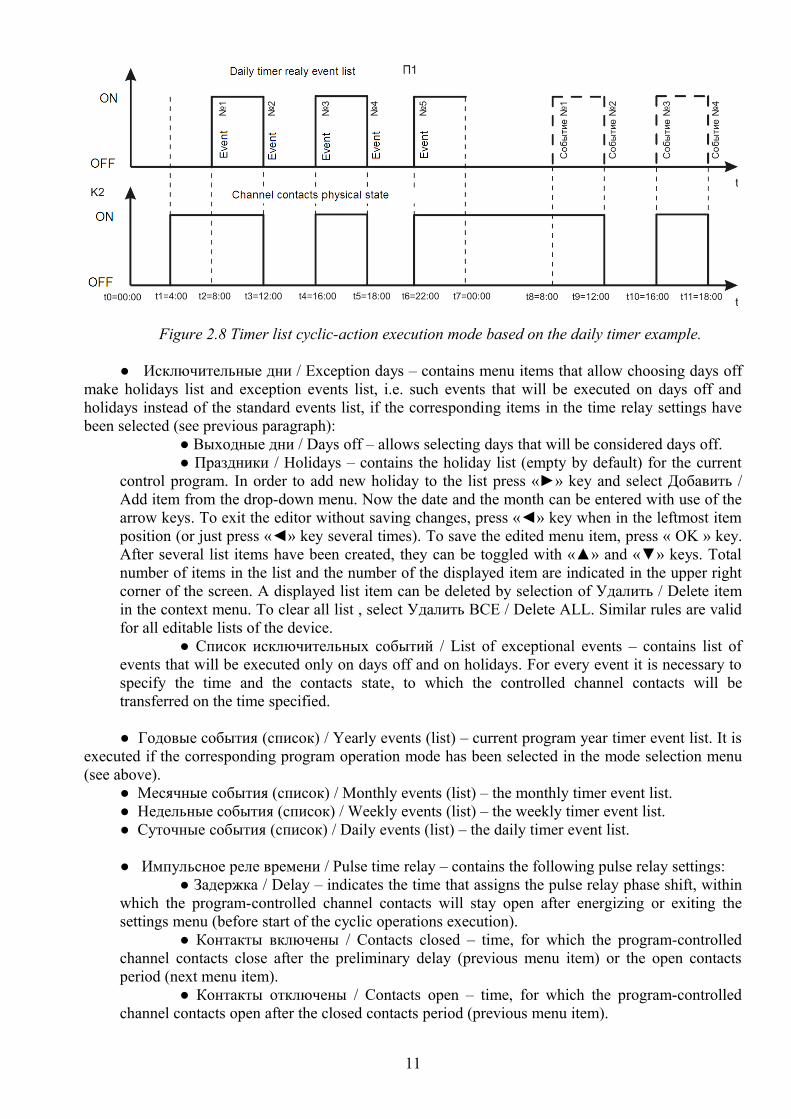
Figure 2.8 Timer list cyclic-action execution mode based on the daily timer example.
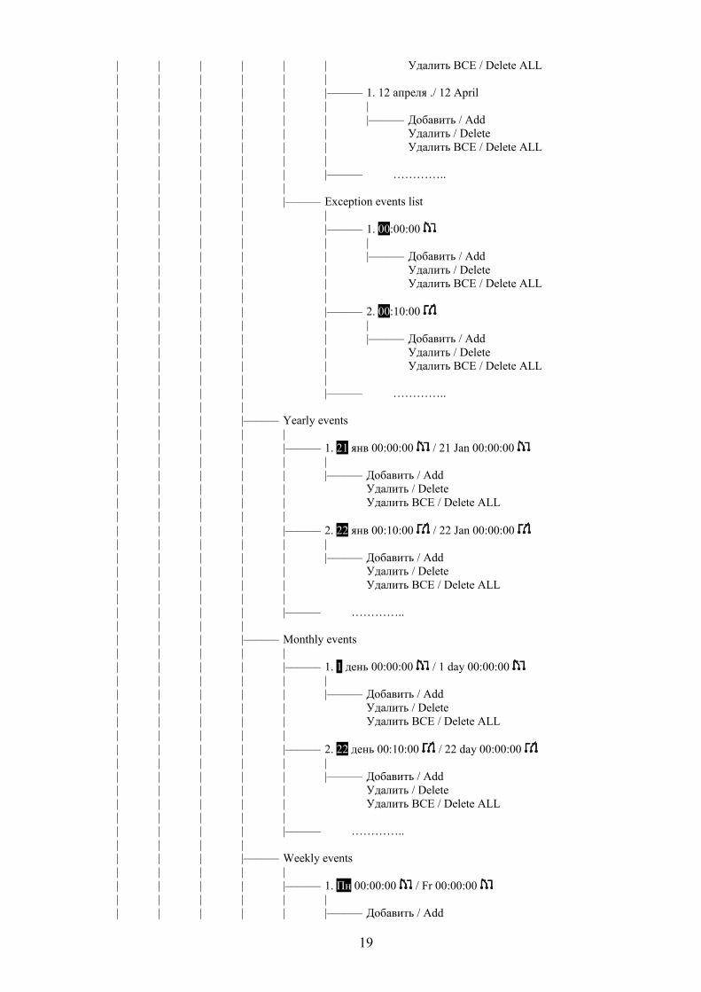
● Исключительные дни / Exception days – contains menu items that allow choosing days off make holidays list and exception events list, i.e. such events that will be executed on days off and holidays instead of the standard events list, if the corresponding items in the time relay settings have been selected (see previous paragraph):
● Выходные дни / Days off – allows selecting days that will be considered days off.● Праздники / Holidays – contains the holiday list (empty by default) for the current
control program. In order to add new holiday to the list press «►» key and select Добавить / Add item from the drop-down menu. Now the date and the month can be entered with use of the arrow keys. To exit the editor without saving changes, press «◄» key when in the leftmost item position (or just press «◄» key several times). To save the edited menu item, press « OK » key. After several list items have been created, they can be toggled with «▲» and «▼» keys. Total number of items in the list and the number of the displayed item are indicated in the upper right corner of the screen. A displayed list item can be deleted by selection of Удалить / Delete item in the context menu. To clear all list , select Удалить ВСЕ / Delete ALL. Similar rules are valid for all editable lists of the device.
● Список исключительных событий / List of exceptional events – contains list of events that will be executed only on days off and on holidays. For every event it is necessary to specify the time and the contacts state, to which the controlled channel contacts will be transferred on the time specified.
● Годовые события (список) / Yearly events (list) – current program year timer event list. It is executed if the corresponding program operation mode has been selected in the mode selection menu (see above).
● Месячные события (список) / Monthly events (list) – the monthly timer event list.● Недельные события (список) / Weekly events (list) – the weekly timer event list.● Суточные события (список) / Daily events (list) – the daily timer event list.
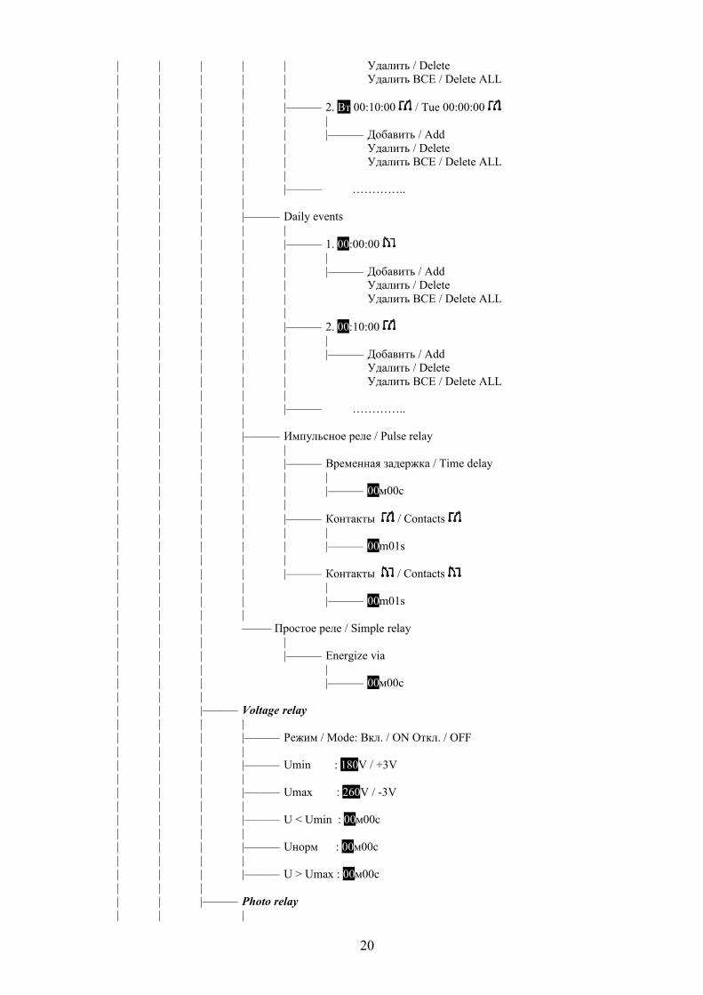
● Импульсное реле времени / Pulse time relay – contains the following pulse relay settings:● Задержка / Delay – indicates the time that assigns the pulse relay phase shift, within
which the program-controlled channel contacts will stay open after energizing or exiting the settings menu (before start of the cyclic operations execution).
● Контакты включены / Contacts closed – time, for which the program-controlled channel contacts close after the preliminary delay (previous menu item) or the open contacts period (next menu item).
● Контакты отключены / Contacts open – time, for which the program-controlled channel contacts open after the closed contacts period (previous menu item).
11
● Простое реле времени / Simple time relay – consists of one item only, where the delay is assigned, upon expiration of which after the system energizing or the settings menu exit, the program-controlled channel contacts will be closed.
2.3.2 Voltage relay
The voltage relay within each Px program, if it is on, monitors the voltage on terminals 7-8. If the voltage falls below the Umin threshold or exceeds the Umax threshold, then, after the set time, the contacts of the Pх program controlled Кх channel will be opened regardless of the active time relay or the photo relay settings. The control will be handed over to the time relay or the photo relay after the assigned restart time, upon return of the circuit voltage (U) to the range of
(Umin + dUmin) < U < (Umax – dUmax),
where dUmin and dUmax are the tolerance zones assigned in the settings, which allow to remove false contact commutations in case of insignificant voltage fluctuations near the Umin and Umax thresholds.
To set up the voltage relay of one of the control programs Px, perform the following menu sequence: Меню / Menu ► Настройка программ / Programs options ► Программа Пx / Px program► Реле напряжения / Voltage relay, which contains the following menu items:
● Режим / Mode – allows switching the voltage relay on or off within the current control program.
● Umin – sets up the bottom working range threshold with the dUmin positive tolerance zone.● Umax – sets up the upper working range threshold with the dUmax negative tolerance zone.● U < Umin – setting the time delay before the program controlled channel contacts are opened
in case of low circuit voltage.● Uнорм – setting of the time delay effective before the control over the program controlled
channel contacts is transferred to the time relay or the photo relay in case circuit voltage is restored to normal.
● U < Umin – setting the time delay before the program controlled channel contacts are opened in case of high circuit voltage.
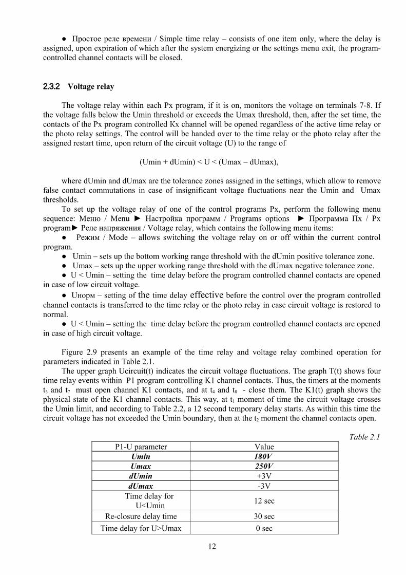
Figure 2.9 presents an example of the time relay and voltage relay combined operation for parameters indicated in Table 2.1.
The upper graph Ucircuit(t) indicates the circuit voltage fluctuations. The graph T(t) shows four time relay events within P1 program controlling K1 channel contacts. Thus, the timers at the moments t3 and t7 must open channel K1 contacts, and at t4 and t8 - close them. The K1(t) graph shows the physical state of the K1 channel contacts. This way, at t1 moment of time the circuit voltage crosses the Umin limit, and according to Table 2.2, a 12 second temporary delay starts. As within this time the circuit voltage has not exceeded the Umin boundary, then at the t2 moment the channel contacts open.
Table 2.1P1-U parameter Value
Umin 180V Umax 250VdUmin +3VdUmax -3V
Time delay for U<Umin 12 sec
Re-closure delay time 30 secTime delay for U>Umax 0 sec
12
While the voltage is below Umin+3V, the events at t3 and t4 are ignored. As soon as the voltage exceeds the Umin+3V threshold (t5) , the 30 sec re-closure delay begins, and it ends at t6 instance, and the control is transferred to the P1 program time relay, according to which the channel contacts are to be closed. At t7 and t8 moments the contacts commutation which corresponds to the time relay requirement, takes place. At t9 moment of time the circuit voltage exceeds the Umax threshold, and, as according to Table 2.2 the time delay is equal to 0, the channel contacts are opened immediately.
Figure 2.9.Example of time relay and voltage relay combined operation.
2.3.3 Photo relay
The photo relay uses an external sensor connected to terminals 11-12 to analyze illumination intensity. Table 2.2 gives approximate illumination levels for different situations:
Table 2.2Description Illumination, lx
Sunlight at midday 100 000Film shooting in a studio 10 000Open area on an overcast day 1000Light room near window 100Work desk for precise operations 400–500Cinema screen 85–120Required for writing 30–50Full moon 0,2Night sky on a moonless night 0,0003
13

Table 2.3 gives accepted illumination standards:Table 2.3
Room typeIllumination level (lx) according to standards
Russian (СНиП 23-05-95) International (МКО)
General purpose offices with use of computers 200-300 500
Large floor offices with free layout 400 750
Offices with drawing operations 500 1000
Conference halls 200 300Stairs, escalators 50-100 150Corridors, lobbies 50-75 100Archives 75 200Storages 50 100
To set up the photo relay of one of the Px control programs, perform the following menu sequence: Меню / Menu ► Настройка программ / Programs options ► Программа Пx / Px program► Фотореле / Photo relay, which contains the following menu items:
● Режим / Mode – allows switching the photo relay on or off within the current control program.
● Порог освещенности / Illumination threshold – the level of illumination (lux), above or below which the contacts must be switched;
● Гистерезис / Hysteresis (default +5 lx) – eliminates repetitive channel contacts commutations in case of illumination fluctuation about the set threshold;
● L < Lthr – setting temporary delay before executing a low illumination triggered event.● L > Lthr – setting temporary delay before executing a high illumination triggered event.● Контакты L < Lпор / L < Lthr Contacts – includes a list to pick up a type of action executed
on contacts upon a low illumination event:● только ВЫКЛ / only OFF - while the above illumination condition is active, the
contacts will be open. ● только ВКЛ / only ON - while the above illumination condition is active, the
contacts will be closed.● Соответствовать реле времени / Correspond to the time relay – while the above
illumination condition is active, the contacts will controlled by the time relay. If the time relay is not activated (off), the contacts will be off as well.
● ОТКЛ. до события / OFF till event – after the above illumination event activation the contacts will be opened once, after which the next time relay event may change their position.
● ВКЛ. до события / ON till event – after the above illumination event activation the contacts will be closed once, after which the next time relay event may change their position.● Контакты L > Lпор / L > Lthr Contacts – includes a list similar to the previous item to pick
up a type of action executed on contacts upon a high illumination event.
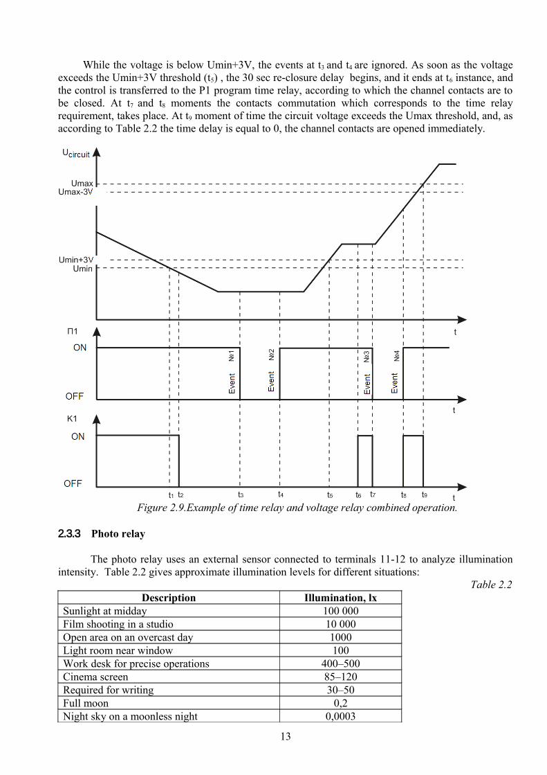
Figure 2.10 presents one of the examples of time relay and photo relay combined operation. It is required that contacts close after the illumination level falls below 150 lux, and open at 3:00 AM, even if the illumination level remains below Lthr threshold. Table 2.4 presents necessary values for the
14
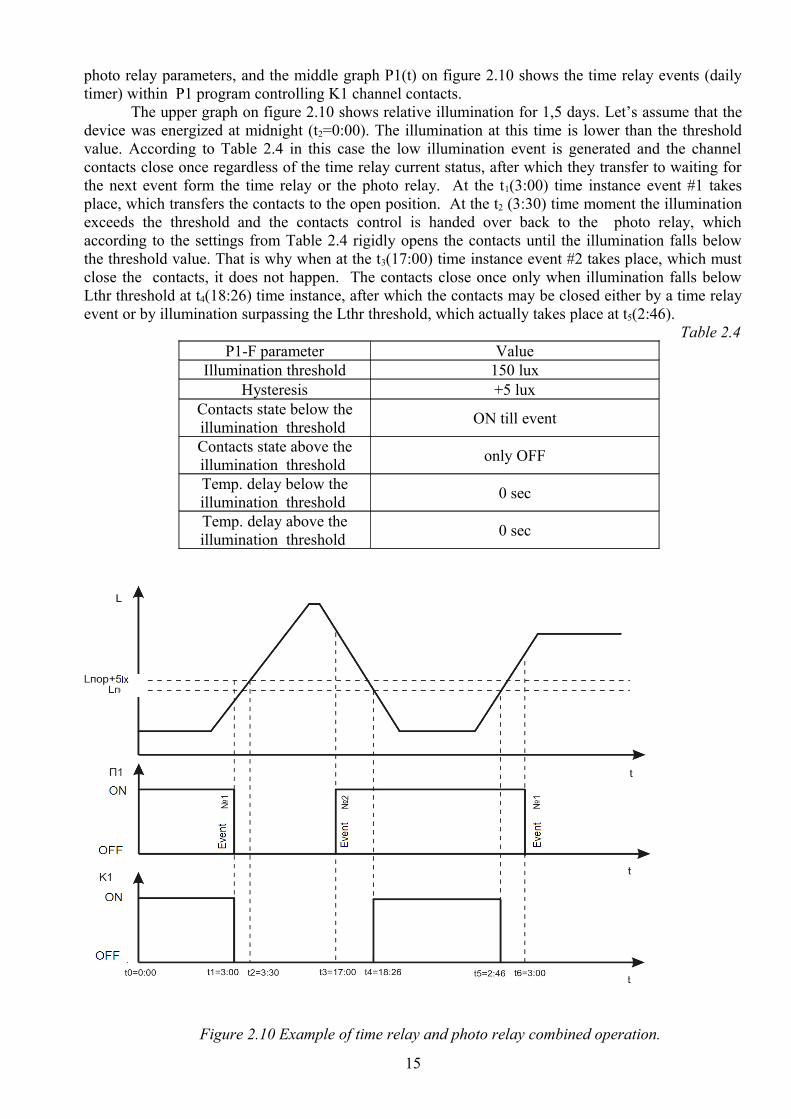
photo relay parameters, and the middle graph P1(t) on figure 2.10 shows the time relay events (daily timer) within P1 program controlling K1 channel contacts.
The upper graph on figure 2.10 shows relative illumination for 1,5 days. Let’s assume that the device was energized at midnight (t2=0:00). The illumination at this time is lower than the threshold value. According to Table 2.4 in this case the low illumination event is generated and the channel contacts close once regardless of the time relay current status, after which they transfer to waiting for the next event form the time relay or the photo relay. At the t1(3:00) time instance event #1 takes place, which transfers the contacts to the open position. At the t2 (3:30) time moment the illumination exceeds the threshold and the contacts control is handed over back to the photo relay, which according to the settings from Table 2.4 rigidly opens the contacts until the illumination falls below the threshold value. That is why when at the t3(17:00) time instance event #2 takes place, which must close the contacts, it does not happen. The contacts close once only when illumination falls below Lthr threshold at t4(18:26) time instance, after which the contacts may be closed either by a time relay event or by illumination surpassing the Lthr threshold, which actually takes place at t5(2:46).
Table 2.4P1-F parameter Value
Illumination threshold 150 luxHysteresis +5 lux
Contacts state below the illumination threshold ON till event
Contacts state above the illumination threshold only OFF
Temp. delay below the illumination threshold 0 sec
Temp. delay above the illumination threshold 0 sec
Figure 2.10 Example of time relay and photo relay combined operation.
15
2.3.4 Software
Setting up REV-302.01 via special software brings the following advantages:- graphic representation of all device parameters; - quick toggling between parameters and possibility to edit them globally; - option of saving the device settings images to file on the PC hard drive, which allows creating
different device configurations and quickly load them when necessary, etc.;The latest software version can be downloaded from www.novatek-electro.com. website. To
work with the software use the dynamic prompt and explanations.
3 PACKAGE CONTENTS
REV-302.01 device………………………………………………………………………. 1 pc.Photo sensor with connection cable…………………………………………………...….. 1 pc.CCP-USB2-AM5P-6 cable or similar………………………………………………….…. 1 pc.Operation manual………………………………………………………………………..… 1 pc.Packing…………………………………………………………………………………….. 1 pc.
4 MAINTENANCE
4.1 SAFETY During maintenance operations, REV-302.01 power supply must be disconnected.
4.2 Maintenance scheduleRecommended maintenance schedule – semiannually.Maintenance scheduled operations consist of visual observation, during which wiring
connection to REV-302.01 terminals is checked, casing integrity check for cracking and chipping.
5 PERIOD OF SERVICE AND STORAGE, AND MANUFACTURER’S WARRANTY
The REV-302.01 has 10 years life period. Upon expiration of the service period, please, contact the manufacturer.
The manufacturer warrants defect-free performance of REV-302.01 within thirty-six months after the sales date, provided that the following conditions have been met:
- proper installation;- manufacturer’s QC department inspection seal is intact;- integrity of the device case, no traces of opening, cracks, chipping, etc.
6 TRANSPORTATION
Transportation of REV- 302.01 in package may be effected by any type of transport according to the transportation rules and regulations valid for such mode transportation.
During transportation, shipping and storing in a warehouse REV- 302.01 must be protected form blows, shocks and moisture.
16

7 ACCEPTANCE CERTIFICATE
The REV- 302.01 multifunctional programmable year timer with voltage relay and photo relay functions # ______________ has been manufactured and accepted in conformity with the requirements of current technical documentation, and is approved fit for operation.
QC department supervisor Production date
(SEAL) _____________ Date of manufacture______________
8 NOTICES OF CLAIMS
The manufacturer shall not accept any notices of defect if the equipment failed due to consumer’s improper operation or due to non-fulfillment of instructions provided herein.
The manufacturer reserves the right to make alterations and additions to the product design and software not impairing the device’s technical characteristics, and does not undertake to inform anybody of such alterations and additions.
With questions and comments, please contact manufacturer at the following address:
NOVATEK INDIA ENTERPRISES PVT. LTD. 57-A, Pocket-A, Mayur Vihar Ph-II, Delhi - 91
Tel: 011 - 43089550, Fax: 011 - 43089581 www.novatek-electro.com
Date of sale _______________
17
Enclosure A. REV-302.01 principal menu items structure
Menu||–––––– Канал К1 / K1 Channel | || |–––––– Режим K1 / K1 mode| || |–––––– ○ Откл. / OFF| ● Прогр. / Program P1| ………..| ○ Прогр. / Program P8||–––––– Канал К2 / K2 Channel| || |–––––– Режим K2 / K2 mode| || |–––––– ○ Откл. / OFF| ● Прогр. П1 / Program P1| ………..| ○ Прогр. П8 / Program P8||–––––– Programs options | || |–––––– Программа / Program P1| | || | |–––––– Реле времени / Time relay| | | || | | |–––––– Режим / Mode| | | | || | | | |–––––– ○ Отключить / De-energize| | | | ● Годовое реле / Yearly relay timer| | | | ○ Месячное реле / Monthly relay| | | | ○ Недельное реле / Weekly relay| | | | ○ Суточное реле / Daily relay| | | | ○ Импульсное реле / Pulse relay| | | | ○ Простое реле / Simple relay| | | || | | |–––––– Настройки реле времени / Time relay setting| | | | || | | | |–––––– □ Учитывать выходные / Recognize days off.| | | | □ Учитывать праздники / Recognize holidays| | | | ■ Повторять циклически / Cycle rotation | | | || | | |–––––– Исключительные дни / Exception days| | | | || | | | |–––––– Выходные / Days off| | | | | || | | | | |–––––– □ Пн. / Mon| | | | | □ Вт. / Tue| | | | | □ Ср. / Wed| | | | | □ Чт. / Thu| | | | | □ Пт. / Fr| | | | | ■ Сб. / Sat| | | | | ■ Вс. /Sun| | | | || | | | |–––––– Праздники / Holidays| | | | | || | | | | |–––––– 1. 10 April| | | | | | || | | | | | |–––––– Добавить / Add| | | | | | Удалить / Delete
18
| | | | | | Удалить ВСЕ / Delete ALL| | | | | || | | | | |–––––– 1. 12 апреля ./ 12 April| | | | | | || | | | | | |–––––– Добавить / Add| | | | | | Удалить / Delete| | | | | | Удалить ВСЕ / Delete ALL| | | | | || | | | | |–––––– …………..| | | | || | | | |–––––– Exception events list| | | | || | | | |–––––– 1. 00:00:00 | | | | | || | | | | |–––––– Добавить / Add| | | | | Удалить / Delete| | | | | Удалить ВСЕ / Delete ALL| | | | || | | | |–––––– 2. 00:10:00 | | | | | || | | | | |–––––– Добавить / Add| | | | | Удалить / Delete| | | | | Удалить ВСЕ / Delete ALL| | | | || | | | |–––––– …………..| | | || | | |–––––– Yearly events| | | | || | | | |–––––– 1. 21 янв 00:00:00 / 21 Jan 00:00:00 | | | | | || | | | | |–––––– Добавить / Add| | | | | Удалить / Delete| | | | | Удалить ВСЕ / Delete ALL| | | | || | | | |–––––– 2. 22 янв 00:10:00 / 22 Jan 00:00:00 | | | | | || | | | | |–––––– Добавить / Add| | | | | Удалить / Delete| | | | | Удалить ВСЕ / Delete ALL| | | | || | | | |–––––– …………..| | | || | | |–––––– Monthly events| | | | || | | | |–––––– 1. 1 день 00:00:00 / 1 day 00:00:00 | | | | | || | | | | |–––––– Добавить / Add| | | | | Удалить / Delete| | | | | Удалить ВСЕ / Delete ALL| | | | || | | | |–––––– 2. 22 день 00:10:00 / 22 day 00:00:00 | | | | | || | | | | |–––––– Добавить / Add| | | | | Удалить / Delete| | | | | Удалить ВСЕ / Delete ALL| | | | || | | | |–––––– …………..| | | || | | |–––––– Weekly events| | | | || | | | |–––––– 1. Пн 00:00:00 / Fr 00:00:00 | | | | | || | | | | |–––––– Добавить / Add
19
| | | | | Удалить / Delete| | | | | Удалить ВСЕ / Delete ALL| | | | || | | | |–––––– 2. Вт 00:10:00 / Tue 00:00:00 | | | | | || | | | | |–––––– Добавить / Add| | | | | Удалить / Delete| | | | | Удалить ВСЕ / Delete ALL| | | | || | | | |–––––– …………..| | | || | | |–––––– Daily events| | | | || | | | |–––––– 1. 00:00:00 | | | | | || | | | | |–––––– Добавить / Add| | | | | Удалить / Delete| | | | | Удалить ВСЕ / Delete ALL| | | | || | | | |–––––– 2. 00:10:00 | | | | | || | | | | |–––––– Добавить / Add| | | | | Удалить / Delete| | | | | Удалить ВСЕ / Delete ALL| | | | || | | | |–––––– …………..| | | || | | |–––––– Импульсное реле / Pulse relay| | | | || | | | |–––––– Временная задержка / Time delay| | | | | || | | | | |–––––– 00м00с| | | | || | | | |–––––– Контакты / Contacts | | | | | || | | | | |–––––– 00m01s| | | | || | | | |–––––– Контакты / Contacts | | | | || | | | |–––––– 00m01s| | | || | | ––––– Простое реле / Simple relay| | | || | | |–––––– Energize via| | | || | | |–––––– 00м00с| | || | |–––––– Voltage relay| | | || | | |–––––– Режим / Mode: Вкл. / ON Откл. / OFF| | | || | | |–––––– Umin : 180V / +3V| | | || | | |–––––– Umax : 260V / -3V| | | || | | |–––––– U < Umin : 00м00с| | | || | | |–––––– Uнорм : 00м00с| | | || | | |–––––– U > Umax : 00м00с| | || | |–––––– Photo relay| | |
20

| | |–––––– Режим / Mode: Вкл. / ON Откл. / OFF| | || | |–––––– Порог / Threshold : 100 lux| | || | |–––––– Hyst., sec” +5 lux| | || | |–––––– L < Lthr : 00m00sec| | || | |–––––– L > Lthr : 00m00sec| | || | |–––––– U > Umax : 00m00sec| | || | |–––––– Контакты L < Lthr / Contacts L < Lthr :| | | || | | |–––––– ● только / only | | | ○ только / only | | | ○ повторять реле времени / Time relay repeat| | | ○ Till event| | | ○ до события / till event| | || | |–––––– Контакты L > Lthr / Contacts L > L | | || | |–––––– ○ только / only | | ● только / only | | ○ повторять реле времени / Time relay repeat| | ○ до события / till event| | ○ до события / till event| || || |–––––– Программа / Program П2| || |–––––– ……………| || |–––––– Программа / Program П8|
| ––––– Settings| || |–––––– Задержка на вкл. / Start delay | | || | |–––––– 00h00m00sec| || |–––––– Время / Time 00 : 00 : 00| || |–––––– Дата / Date : 11 ноября / 11 November| || |–––––– Год / Year : 2010| || |–––––– Летн. вр. ВКЛ / Summer time ON Откл. / OFF| || |–––––– Задержка / Delay: 00m00sec| || |–––––– Коррекция напряж / Voltage correction: 218 V| || |–––––– Коррекция освещенности:: / Illumination correction: 135 lux| || |–––––– Сброс настр. в заводск. / Reset settings to default| | || | |–––––– Да / Нет Yes / No|| ––––– Управление / Control| || |–––––– Очистить память / Clear memory| | |
21
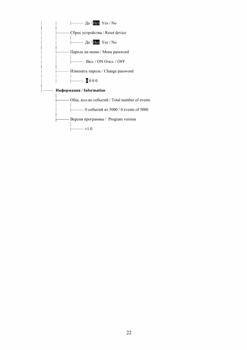
| | |–––––– Да / Нет Yes / No| || |–––––– Сброс устройства / Reset device| | || | |–––––– Да / Нет Yes / No| || |–––––– Пароль на меню / Menu password| | || | |–––––– Вкл. / ON Откл. / OFF| || |–––––– Изменить пароль / Change password| | || | |–––––– 0 0 0 0|| ––––– Информация / Information
||–––––– Общ. кол-во событий / Total number of events| || |–––––– 0 событий из 5000 / 0 events of 5000||–––––– Версия программы / Program version
||–––––– v1.0
22