Embed Size (px)
Citation preview
Multifunctional Nanocomposites for
Aerospace Applications: Overview
CHEOL PARK
Advanced Materials and Processing Branch
NASA Langley Research Center
Hampton, VA 23681, USA
University of California, Merced
March 13, 2015
NASA Langley Research Center
NASA Langley Research Center
Catharine Fay, Sharon Lowther, Wanda Gresham, Joseph Lee, Hoa Luong, Peter Gnoffo, Paul
Danehy, Jennifer Inman, Steve Jones, Sheila Thibeault, Kristopher Wise, Andy Newman,
Robert Bryant, Crystal Topping, Dennis Working, Keith Gordon, Sang Choi
National Institute of Aerospace
Vesselin Yamakov, Godfrey Sauti, Jin Ho Kang, Hyun Jung Kim, Sang-Hyon Chu, Luke Gibbons,
Samantha Applin, Amanda Tiano
SUNY Binghamton
Meng Zheng, Xiaoming Chen, Changhong Ke, Howard Wang
NASA C&I, B&P, GCD, IRAD, NIAC
Acknowledgements
Rice University
Mohammad Adnan, Matteo Pasquali
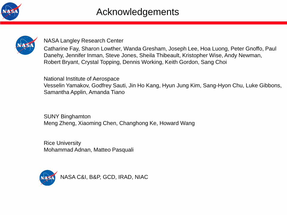
NASA Langley Research Center Hampton, Virginia
Founded in 1917: first civil aeronautical research laboratory
Facilities: $4 billion replacement value
People: 2000 Civil Servants ; 1700 Contractors
NASA Langley Research Center
All images credit: NASA

All images credit: NASA
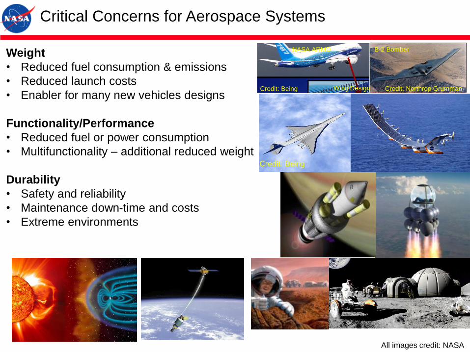
Weight
• Reduced fuel consumption & emissions
• Reduced launch costs
• Enabler for many new vehicles designs
Functionality/Performance
• Reduced fuel or power consumption
• Multifunctionality – additional reduced weight
Durability
• Safety and reliability
• Maintenance down-time and costs
• Extreme environments
Critical Concerns for Aerospace Systems
B-2 Bomber
Credit: Northrop Grumman
NASA ARMD
Wing DesignCredit: Being
All images credit: NASA
Credit: Being

Design Materials Properties
Materials Properties to be Tailored
• Electrical Conductivity
• Dielectric Permittivity
• Magnetic Permeability
• Thermal Conductivity/expansion coefficient
• Radiation Shielding
• Mechanical (modulus, strength, toughness…)
• Solar Absorptivity/Thermal Emissivity
• Band gap engineering
• Optical property (transparency, refractive index…)
• Piezoelectricity/Pyroelectricity/Electrostrictive
• Gas/Liquid Permeability
• Anisotropy/orientation
Design Parameters
• Nano Inclusion type and combination (CNT,
BNNT, BCNNT, GP, hBN, NP…)
• Matrix type
• Composition
• Dispersion
• Orientation
• Geometry, Fabrication, Processing…
Specific Applications
• R2R Printing of Electroactive Polymer Composites: NSF/NASA
• Electroactive properties & Radiation Shielding of BNNT Composites: AFOSR/NASA C&I
• Radiation Detection and Conductivity Control: DOE (ORNL)/NASA
• Solar Absorption and Thermal Emission Control: NASA C&I
• Structural BNNT composites, BNNT fibers and mats: Rice Univ/NASA GCD, B&P, IRAD
• Multiple Metal Infusion for Multifunctionality (S2M2N): NASA IRAD
• Bandgap Engineering of nanotubes: NASA IRAD
• Doped Chiral Polymer Metamaterials (DCPM): NASA IRAD
• Radiation Shielding and Thermal Conduction (Electronic Packaging): NASA IRAD
• Ultralight Flexible Shielding Tension Shell: NASA IRAD
• Multifunctional Nanocomposites
• Nanotube Synthesis: High Temperature-Pressure (HTP) BNNT and BCNNT Synthesis
• Dispersion
• Tailoring physical properties of nanocomposites for multifunctions
• Metallized Nanotube Polymer Composites (MNPC)
• Doped Chiral Polymer Metamaterials (DCPM)
• Band Gap Engineering (BxCyNz Nanotubes)
• Sensors/Actuators
• Radiation Shielding
• Summary
Outline
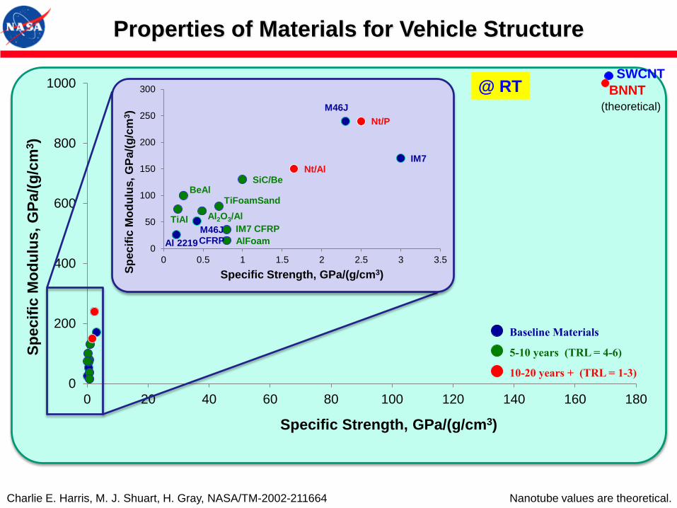
BNNT
0
200
400
600
800
1000
0 20 40 60 80 100 120 140 160 180
Sp
ecif
ic M
od
ulu
s,
GP
a/(
g/c
m3)
Specific Strength, GPa/(g/cm3)
IM7
M46J
M46JCFRPAl 2219
SiC/Be
TiFoamSandBeAl
Al2O3/AlTiAlIM7 CFRP
AlFoam
Nt/P
Nt/Al
0
50
100
150
200
250
300
0 0.5 1 1.5 2 2.5 3 3.5
Sp
ec
ific
Mo
du
lus,
GP
a/(
g/c
m3)
Specific Strength, GPa/(g/cm3)
Baseline Materials
5-10 years (TRL = 4-6)
10-20 years + (TRL = 1-3)
Charlie E. Harris, M. J. Shuart, H. Gray, NASA/TM-2002-211664
Properties of Materials for Vehicle Structure
@ RTSWCNT
Nanotube values are theoretical.
(theoretical)
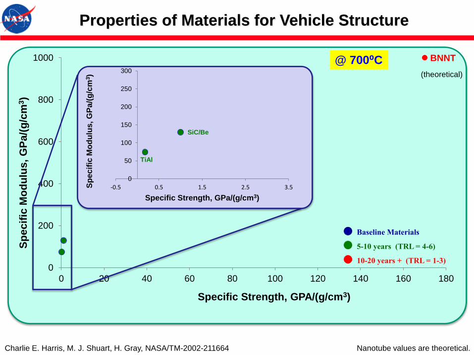
BNNT
0
200
400
600
800
1000
0 20 40 60 80 100 120 140 160 180
Sp
ecif
ic M
od
ulu
s,
GP
a/(
g/c
m3)
Specific Strength, GPA/(g/cm3)
Baseline Materials
5-10 years (TRL = 4-6)
10-20 years + (TRL = 1-3)
Charlie E. Harris, M. J. Shuart, H. Gray, NASA/TM-2002-211664
SiC/Be
TiAl
0
50
100
150
200
250
300
-0.5 0.5 1.5 2.5 3.5Sp
ec
ific
Mo
du
lus,
GP
a/(
g/c
m3)
Specific Strength, GPa/(g/cm3)
@ 700⁰C
Properties of Materials for Vehicle Structure
Nanotube values are theoretical.
(theoretical)

Nanotube Comparison (Theoretical)
Carbon Nanotubes Boron Nitride Nanotubes
Electric Properties Metallic or semiconductingWide band gap (about 6.0 eV
band gap)
Mechanical Properties
(Young’s Modulus)
1.33 TPa
(very stiff)
1.18 TPa
(very stiff)
Thermal Conductivity>3000 W/mK
(highly conductive)
~300–3000 W/mK
(highly conductive)
Thermal Oxidation ResistanceStable up to
300-400 °C in air
Stable to over
800 °C in air
Neutron Absorption
Cross-SectionC = 0.0035 barn
B = 767 barn (B10 ~3800 barn)
N = 1.9 barn
(Excellent radiation shielding)
Polarity No dipolePermanent dipole
Piezoelectric (0.25-0.4 C/m2)
Surface Morphology Smooth
Corrugated
(Provides better bonding for
composites, ionic bonding)
Color BlackWhite
(can be dyed to color)
Coefficient of
Thermal Expansion
-1 x10⁻⁶ K-1
(very low)
-1 x 10⁻⁶ K-1
(very low)
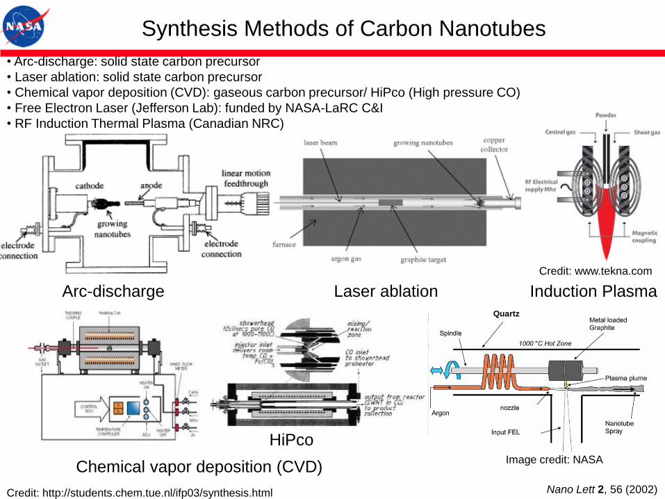
• Arc-discharge: solid state carbon precursor
• Laser ablation: solid state carbon precursor
• Chemical vapor deposition (CVD): gaseous carbon precursor/ HiPco (High pressure CO)
• Free Electron Laser (Jefferson Lab): funded by NASA-LaRC C&I
• RF Induction Thermal Plasma (Canadian NRC)
Synthesis Methods of Carbon Nanotubes
Arc-discharge Laser ablation
Chemical vapor deposition (CVD)
HiPco
Credit: http://students.chem.tue.nl/ifp03/synthesis.html
Quartz
6/8/2014 Induction Plasma Technology - Tekna Plasma Systems Inc
http://tekna.com/equipment/induction-plasma-technology/ 2/3
People are very familiar with the solid, liquid and gaseous states of matter, but not with plasma, the fourth state of matter, which is reached atsufficiently high temperatures and energy densities.
The plasma state is an ionized gas comprising molecules, atoms, ions (in their ground or in various excited states), electrons and photons. It iselectrically conductive since there are free electrons and ions present, and is in local electrical neutrality, since the numbers of free electrons andions are equal. More than 99% of the known universe is in the plasma state. Lightning and auroras are common examples here on Earth.
The high energy content of plasma compared to that of ordinary gases or even the highest temperature combustion flames, offers unlimited potentialfor use in a number of significant modern industrial applications.
In summary, plasma offers:
1. High temperature environment (5 000-10 000K)2. High thermal conductivity3. No combustion necessary4. High purity
Tekna’s Radio Frequency Plasma (RF), or Induction Coupled Plasma (ICP), is generated through the electromagnetic coupling of electricalenergy into a discharge cavity.
A plasma flow generated in an induction plasma torch gives a high-temperature environment (5000 to 10 000 K) with a high specific enthalpy(1-10 MJ/kg, depending on the plasma gas composition). The central axial feeding system provides a more flexible and efficient approach thanDC plasma torchs. Because the residence time is longer than in DC plasmas, the precursor is better treated and the particles are heatedthoroughly.
Tekna’s patented induction plasma torch features:
1. Proprietary ceramic plasma confinement tube2. Coil encapsulated in torch body to facilitate manipulation and maintenance3. Operation under a wide range of conditions with oxidizing, reducing or inert plasma gases4. High-purity processing as the plasma is not generated from an electrical discharge between two electrodes5. Large-volume discharge which allows for a long contact time between the materials to be processed and the plasma6. Solid, liquid or gas precursors7. Exchangeable nozzle designs for low or high velocity plasma discharge
Tekna has developed a complete line of induction plasma torches, with power ratings ranging from 30 kW to 200 kW. For industrial customers wecan provide integrated induction plasma systems for power levels up to 1 MW with outstanding efficiency using our newly developed, patentedprotected, dual frequency induction plasma torch technology.
Induction Plasma
Credit: www.tekna.com
Nano Lett 2, 56 (2002)
Image credit: NASA
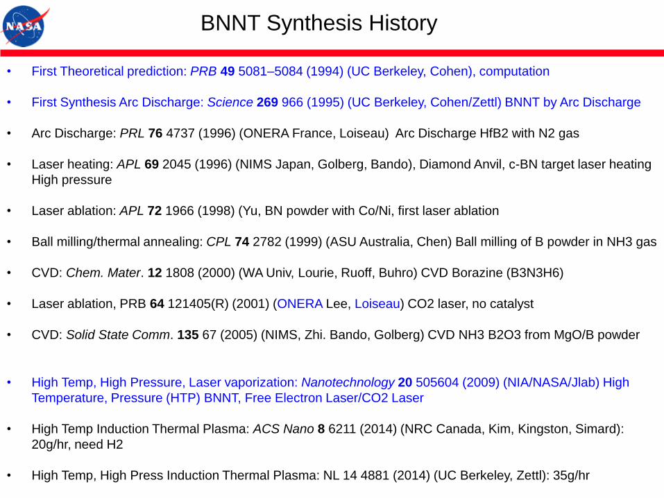
• First Theoretical prediction: PRB 49 5081–5084 (1994) (UC Berkeley, Cohen), computation
• First Synthesis Arc Discharge: Science 269 966 (1995) (UC Berkeley, Cohen/Zettl) BNNT by Arc Discharge
• Arc Discharge: PRL 76 4737 (1996) (ONERA France, Loiseau) Arc Discharge HfB2 with N2 gas
• Laser heating: APL 69 2045 (1996) (NIMS Japan, Golberg, Bando), Diamond Anvil, c-BN target laser heating
High pressure
• Laser ablation: APL 72 1966 (1998) (Yu, BN powder with Co/Ni, first laser ablation
• Ball milling/thermal annealing: CPL 74 2782 (1999) (ASU Australia, Chen) Ball milling of B powder in NH3 gas
• CVD: Chem. Mater. 12 1808 (2000) (WA Univ, Lourie, Ruoff, Buhro) CVD Borazine (B3N3H6)
• Laser ablation, PRB 64 121405(R) (2001) (ONERA Lee, Loiseau) CO2 laser, no catalyst
• CVD: Solid State Comm. 135 67 (2005) (NIMS, Zhi. Bando, Golberg) CVD NH3 B2O3 from MgO/B powder
BNNT Synthesis History
• High Temp, High Pressure, Laser vaporization: Nanotechnology 20 505604 (2009) (NIA/NASA/Jlab) High
Temperature, Pressure (HTP) BNNT, Free Electron Laser/CO2 Laser
• High Temp Induction Thermal Plasma: ACS Nano 8 6211 (2014) (NRC Canada, Kim, Kingston, Simard):
20g/hr, need H2
• High Temp, High Press Induction Thermal Plasma: NL 14 4881 (2014) (UC Berkeley, Zettl): 35g/hr
High Temperature-Pressure (HTP) BNNT and BCNNT
• Free Electron Laser or CO2 laser
• No Catalyst, only B and N resource (and C for BCNNT)
• Very long, small diameter, highly crystalline BNNT, BCNNT
Nanotechnology, 20 505604 (2009)
US Patent Appl US20120171487 A1 (2012) BCNNT
BNNT and BCNNT Synthesis
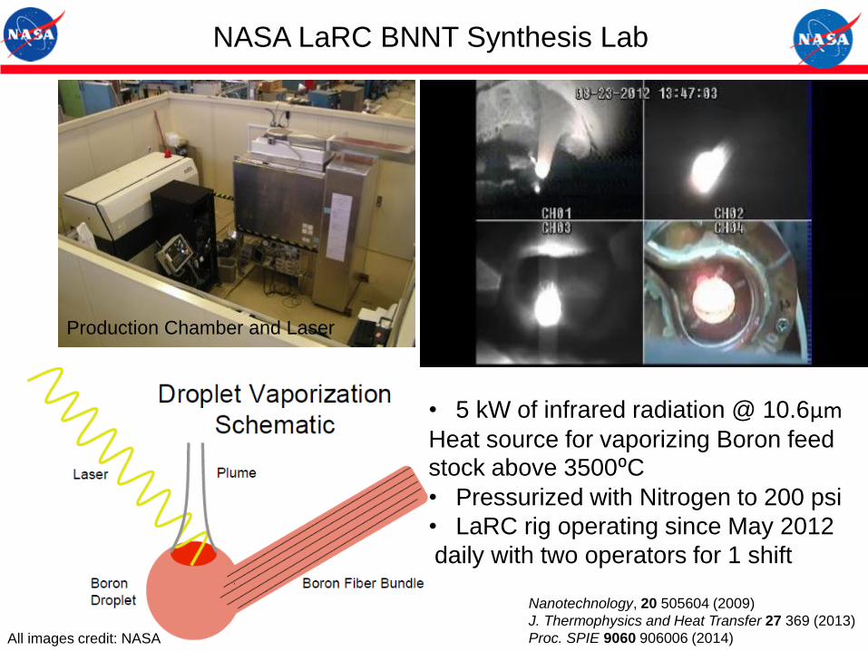
Production Chamber and Laser
NASA LaRC BNNT Synthesis Lab
• 5 kW of infrared radiation @ 10.6µmHeat source for vaporizing Boron feed stock above 3500⁰C• Pressurized with Nitrogen to 200 psi
• LaRC rig operating since May 2012
daily with two operators for 1 shift
Nanotechnology, 20 505604 (2009)
J. Thermophysics and Heat Transfer 27 369 (2013)
Proc. SPIE 9060 906006 (2014)All images credit: NASA

Free Electron Laser: Atmosphere: Spark
All images credit: NASA
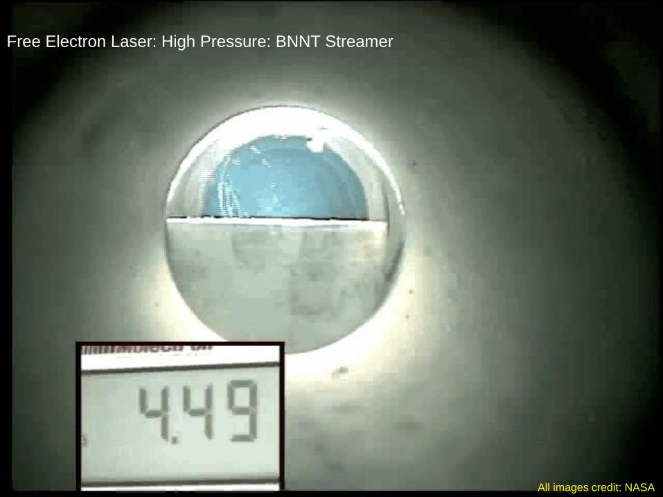
Free Electron Laser: High PressureFree Electron Laser: High Pressure: BNNT Streamer
All images credit: NASA
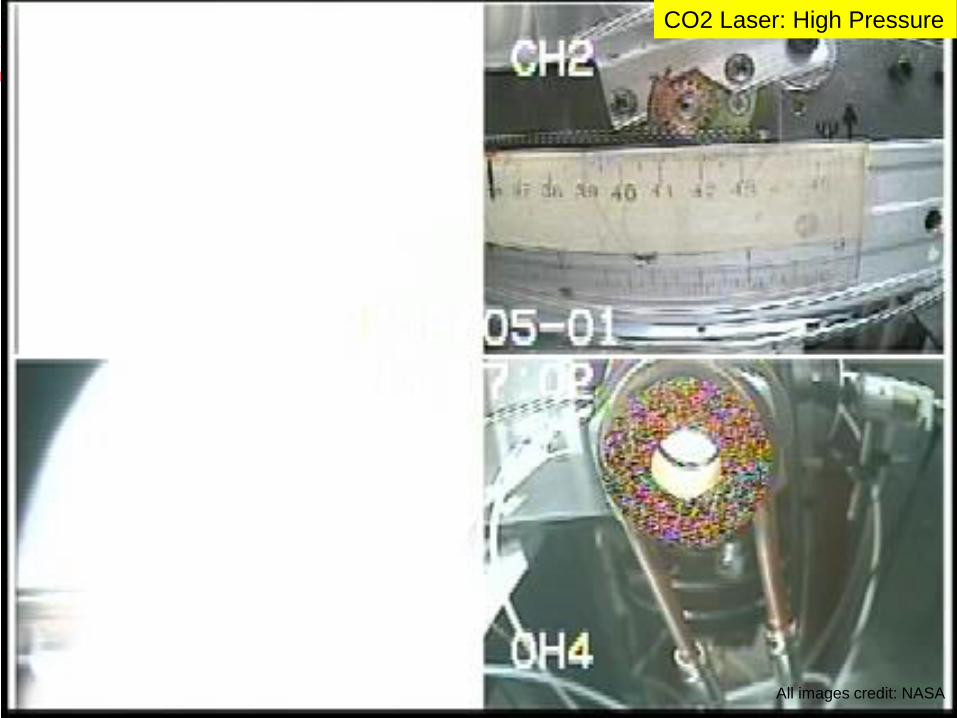
CO2 Laser: High Pressure
All images credit: NASA

Cotton-like High Pressure and Temperature (HPT)-BNNT
Benefits
• One-to-few-walled tubes with high crystallinity
• Very long, high-aspect ratio tubes
• High scale-up potential
• No toxic catalysts (only B and N as reactants)
• Standard industrial cutting/welding lasers
• High service temperature (over 800ºC)
• Highly electroactive (due to the B-N polar bond)
• Neutron radiation shielding (due to their B content)
(~ 30 minutes run time)
All images credit: NASA

High Resolution SEM: As grown BNNT
Nanotechnology, 20 505604 (2009)All images credit: NASA

5 nm dia.
Image: Wei Cao, ODU/ARC
All images credit: NASA
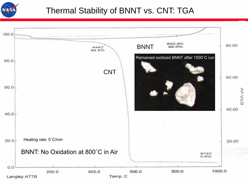
BNNT
CNT
Thermal Stability of BNNT vs. CNT: TGA
BNNT: No Oxidation at 800˚C in Air
Heating rate: 5˚C/min
Remained oxidized BNNT after 1000˚C run

Mechanical Properties of BNNT and BNNT Composites:
Processing and Characterization TechniquesIndividual BNNT and BNNT Bundles: compressive modulus, tensile modulus and strength, radial modulus
substrate
AFM tiph
BNNT
TEM-AFM, TEM-STM Holders
Credit: NASA LaRC/NIA/Binghamton
3D Nanomanipulator in SEM/FIB
Credit: SUNY Binghamton
AFM
Credit: SUNY Binghamton
BNNT composites and BNNT yarns
Spun yarns: NASA LaRC/NIA (credit) Wet spinning/Electrospinning
Credit: NASA LaRC/NIA
200µm
Superacid Spinning
Credit: Rice U
Small, 8, 116 (2012)
ACS Nano, 6, 1814 (2012)
Nanotechnology, 23, 095703 (2012)
σy ≈ cos2 (1-kcosec )·σf
Credit: Hearle, Structural mechanics of fibers, yarns, & fabrics, (1969)
σy: yarn strength, σf: fiber (tube) strength
: helix angle that fibers make with yarn axis
k: (dQ/µ)1/2/3L, d: fiber diameter
µ: coefficient of friction , L: fiber length
Q: fiber migration length
If sf, d, L, µ σy
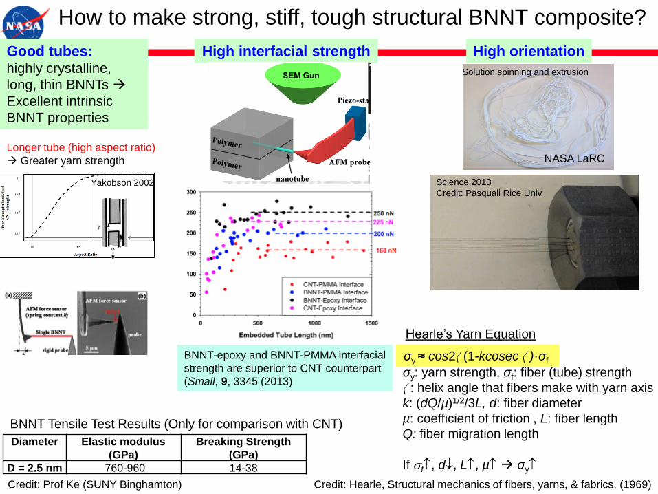
Hearle’s Yarn Equation
Good tubes: highly crystalline,
long, thin BNNTs
Excellent intrinsic
BNNT properties
Diameter Elastic modulus
(GPa)
Breaking Strength
(GPa)
D = 2.5 nm 760-960 14-38
Longer tube (high aspect ratio)
Greater yarn strength
How to make strong, stiff, tough structural BNNT composite?
High interfacial strength
200 nN
160 nN
225 nN
250 nN BNNT-Epoxy
BNNT-PMMA
CNT-PMMA
CNT-Epoxy
How to make strong structural BNNT composite?
Single-tube Pull-out Scheme for interfacial strength
The shear strength of BNNT-Epoxy interface is 22% higher than that of CNT-Epoxy interfaces and
25% higher than that of BNNT-PMMA interfaces.
before pullout after pullout
Small, 9, 3345 (2013)
Diameter Elastic modulus (GPa) Breaking Strength (GPa)
D = 2.5 nm 760-960 14-38
σy ≈ cos2a(1-kcosec a)·σf
Hearle’s Yarn Equation (approx)
σy: yarn strength, σf: fiber (tube) strength
a: helix angle that fibers make with yarn axis
k: (dQ/µ)1/2/3L, d: fiber diameter µ: coefficient of friction , L: fiber length
Q: fiber migration length
If sf, d¯, L, µ σy
longer tube, higher interfacial strength, stronger BNNT, algined BNNT fiber
Binghamton U
High interfacial strength
Longer tube Greater yarn strength
Yakobson (2001)
L > 10 µm
Strong BNNT
BNNT-epoxy and BNNT-PMMA interfacial
strength are superior to CNT counterpart
(Small, 9, 3345 (2013)
High orientation
Solution spinning and extrusion
Science 2013
Credit: Pasquali Rice UnivYakobson 2002
Credit: Prof Ke (SUNY Binghamton)
BNNT Tensile Test Results (Only for comparison with CNT)
NASA LaRC
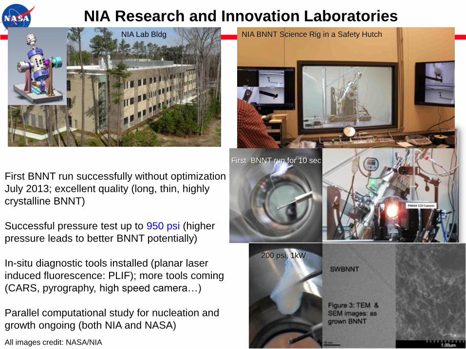
NIA Research and Innovation Laboratories
First BNNT run for 10 sec
First BNNT run successfully without optimization
July 2013; excellent quality (long, thin, highly
crystalline BNNT)
Successful pressure test up to 950 psi (higher
pressure leads to better BNNT potentially)
In-situ diagnostic tools installed (planar laser
induced fluorescence: PLIF); more tools coming
(CARS, pyrography, high speed camera…)
Parallel computational study for nucleation and
growth ongoing (both NIA and NASA)
200 psi, 1kW
NIA Lab Bldg
TEM micrograph &
SEM micrograph:
as grown BNNT
NIA BNNT Science Rig in a Safety Hutch
All images credit: NASA/NIA
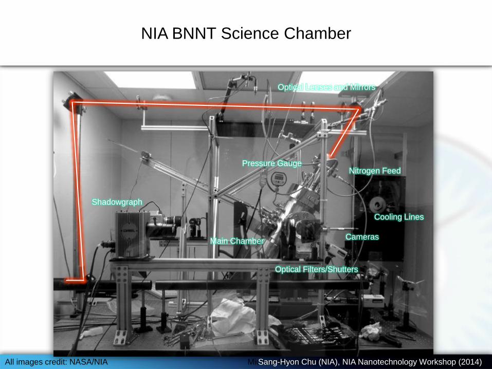
Shadowgraph
Cooling Lines
Optical Filters/Shutters
Pressure Gauge
Cameras
Optical Lenses and Mirrors
Main Chamber
NIA BNNT Science Chamber
Nitrogen Feed
Michael Meador (NASA), NIA Nanotechnology Workshop 2-21-14
NIA BNNT Science Chamber
Sang-Hyon Chu (NIA), NIA Nanotechnology Workshop (2014)All images credit: NASA/NIA

NIA Science Rig HTP BNNT Run (Snapshots)
Molten
boron target
Steady
plume
As grown
BNNT
Proc. SPIE 9060 906006 (2014)
All images credit: NASA/NIA
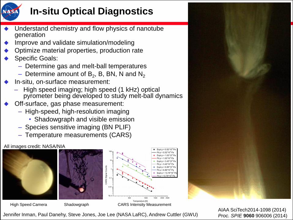
Understand chemistry and flow physics of nanotube generation
Improve and validate simulation/modeling
Optimize material properties, production rate
Specific Goals:
– Determine gas and melt-ball temperatures
– Determine amount of B2, B, BN, N and N2
In-situ, on-surface measurement:
– High speed imaging; high speed (1 kHz) optical pyrometer being developed to study melt-ball dynamics
Off-surface, gas phase measurement:
– High-speed, high-resolution imaging
• Shadowgraph and visible emission
– Species sensitive imaging (BN PLIF)
– Temperature measurements (CARS)
Jennifer Inman, Paul Danehy, Steve Jones, Joe Lee (NASA LaRC), Andrew Cuttler (GWU)
In-situ Optical Diagnostics
High Speed Camera Shadowgraph
AIAA SciTech2014-1098 (2014)
Proc. SPIE 9060 906006 (2014)
CARS Intensity Measurement
All images credit: NASA/NIA

Modeling of Laser Ablation and Plume Chemistry in
a Boron Nitride Nanotube Production Rig
Contour lines of temperatures and mass fraction of BN in the plume
J. Thermophysics and Heat Transfer 27 369 (2013)
Proc. SPIE 9060 906006 (2014)
All images credit: NASA
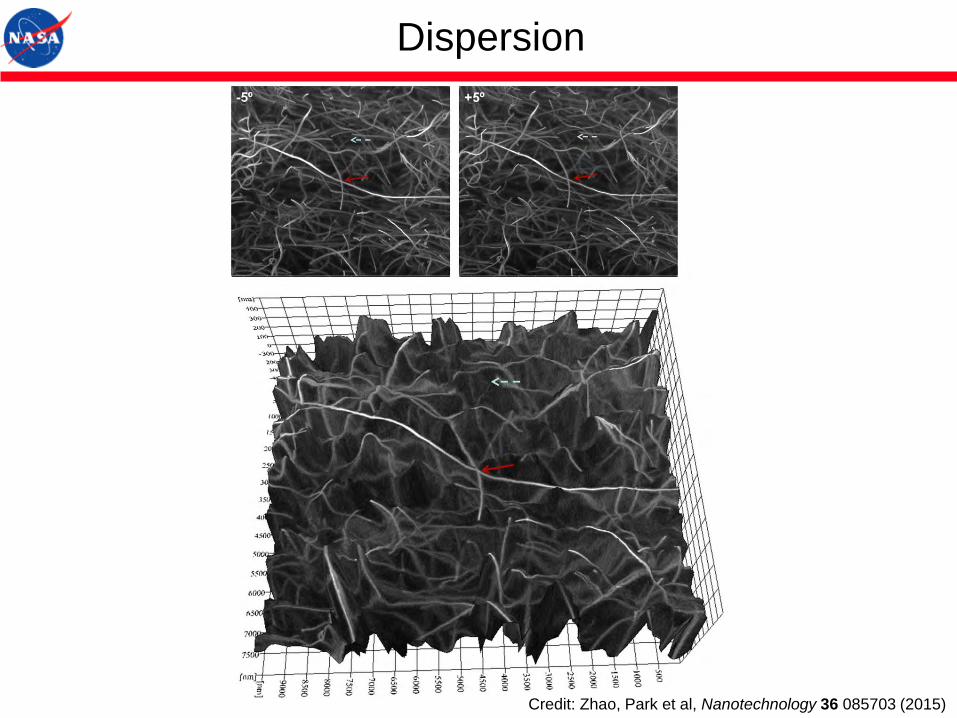
Dispersion
Credit: Zhao, Park et al, Nanotechnology 36 085703 (2015)

How to disperse Nanotubes?
1) Kinetic Approach
High shear (stirring, homogenization, speedmix)
Sonication (cavitational force)
Melt mixing (twin screw mixer, extruder, calendering, capillary rheometer, fiber spinning)
In-situ polymerization
In-situ polymerization under simultaneous sonication & high shear (Chem. Phys. Lett.
364, 303 (2002))
2) Thermodynamic Approach (Minimizing free energy of mixing)
Covalent bonding
Acid etching
Stirring, reflux, and soxhlet extraction with H2SO4, HNO3, and HCl
Functionalization
Fluorination, reflux with amine, electrochemical (diazonium compound)
Non-covalent bonding
Amphiphilic (surfactant), hydrophobic interaction: Water soluble polymers
Wrapping: PmPV, Polyvinyl pyrrolidone, Polystyrene sulfonate, PPE
Charge Transfer (Donor-acceptor) (Chem. Phys. Lett. 391, 207 (2004))
Dispersion Interaction (London force, Permittivity matching)
Solvent or Co-solvent selection (Hansen solubility parameter, surface energy)
Similar size/structure to SWCNT
Zwitterion
Complex formation
Nonspecific interaction
DGmix = DHmix – T*DSmix
Encyclopedia of Nanoscience and Nanotechnology, 2nd Ed, Chapter: Polymer Nanocomposites and
Functionalities, American Scientific Publishers, vol 21 171-218 (2011) (www.aspbs.com/enn)

Probe Microscopy
Nano Letters 4, 61 (2004)
Z Z
S SExperiment
Modeling
• Using Functionalized AFM tips interaction forces can be directly probed.
Alkyl-thiol Endgroup Experiment
Force/Molecule (pN)
Modeling
(pN)
–OH 9.6 ± 2
–perfluoro 8.7 ± 3
–SH 9.2 ± 3
–CH=CH2 8.1 ± 2
–CH3 7.6 ± 2 1.92
–COOH 12.2 ± 3
–NH2 23.4 ± 4 2.98
Aryl-thiol Endgroup
4-methylbenzene 18.9 ± 5.7
4-nitrobenzene 21.8 ± 5.3
4-aminebenzene 22.6 ± 4.7
4-bromobenzene 26.9 ± 3.6
4-hydroxybenzene 32.0 ± 8.4
4-fluorobenzene 39.5 ± 8.8
4-methoxybenzene 41.5 ± 10.9
H-benzene 46.8 ± 11.8
4-Nitrilebenzene 56.9 ±15.5
Proceedings of 31st Adhesion Society Meeting, p39, Ed. by G. Anderson, Austin TX, Feb (2008)
Adhesion Between Nanotubes & Various Functional Groups
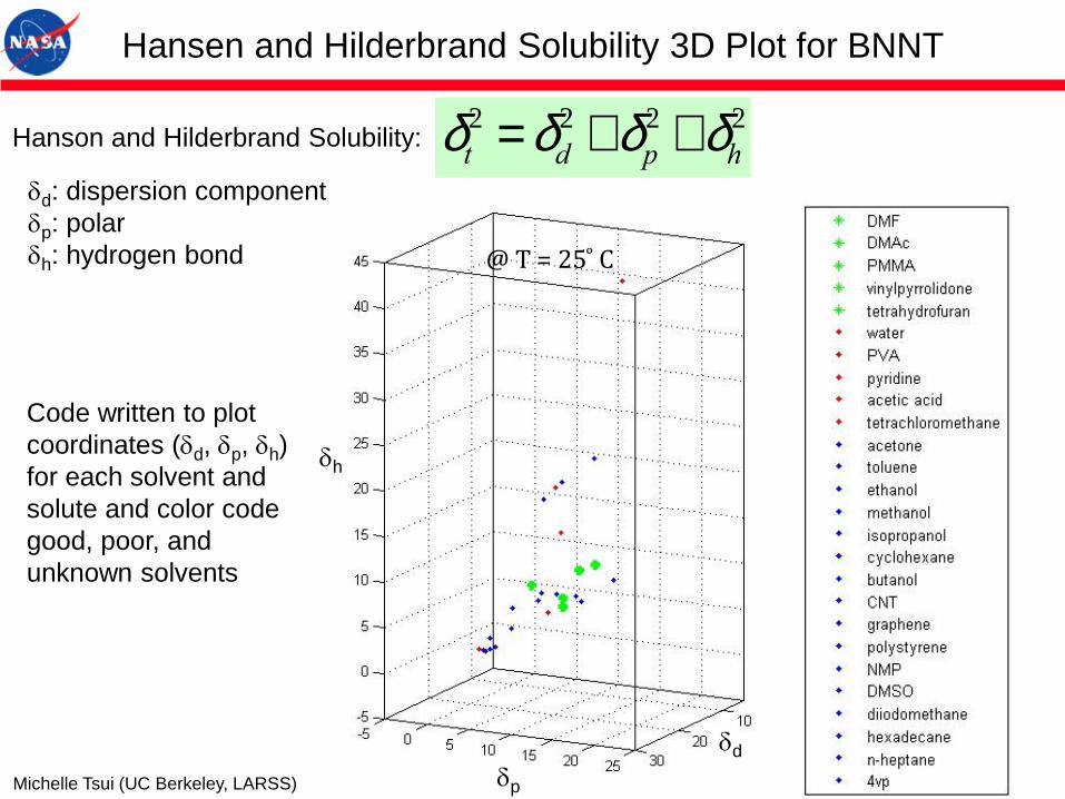
Hansen and Hilderbrand Solubility 3D Plot for BNNT
@ T = 25 ͦ C
Code written to plot
coordinates (dd, dp, dh)
for each solvent and
solute and color code
good, poor, and
unknown solvents
dp
dd
dh
dt2 =dd
2 +dp2 +dh
2Hanson and Hilderbrand Solubility:
dd: dispersion component
dp: polar
dh: hydrogen bond
Michelle Tsui (UC Berkeley, LARSS)
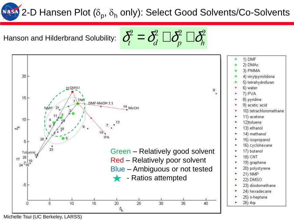
DMF-MeOH 1:1
Green – Relatively good solvent
Red – Relatively poor solvent
Blue – Ambiguous or not tested
- Ratios attempted
2-D Hansen Plot (dp, dh only): Select Good Solvents/Co-Solvents
dt2 =dd
2 +dp2 +dh
2Hanson and Hilderbrand Solubility:
Michelle Tsui (UC Berkeley, LARSS)

Building Blocks: SWCNT/Polymer Nanocomposites
(b-CN)APB/ODPA (Tg = 220°C)
Polyimide + SWNT
Electroactive High Performance Polyimide
Park et al, Chem. Phys. Lett., 364 303 (2002)
Wise et al, Chem. Phys. Lett. 391 207 (2004)
Good Dispersion
• Dispersion Interaction
• Donor-Acceptor interaction
• In-situ Polymerization under
sonication and shear
MFM
Ultrasonic holographyAll images credit: NASA

HRSEM: Well Dispersed SWCNT in Polyimide (2D & 3D)
500nm
All images credit: NASA

Tailoring Physical Property for Multifunctions
Materials Properties to be Tailored
• Electrical Conductivity
• Dielectric Permittivity
• Magnetic Permeability
• Thermal Conductivity/expansion coefficient
• Radiation Shielding
• Mechanical (modulus, strength, toughness…)
• Solar Absorptivity
• Thermal Emissivity
• Band gap engineering
• Optical property (transparency, refractive index…)
• Piezoelectricity/Pyroelectricity/Electrostrictive
• Gas/Liquid Permeability
• Anisotropy/orientation
Design Parameters
• Nano Inclusion type and combination (CNT,
BNNT, BCNNT, GP, hBN, NP…)
• Matrix type
• Composition
• Dispersion
• Orientation
• Geometry, Fabrication, Processing…

Versatility of SWCNT Electroactive Polymer Nanocomposites
• In the vicinity of percolation, the composite acts as a dielectric material and yields
an enhanced sensor response
• Above percolation, the composite is conductive (anti-static) and can be used as an electrostatic actuator
• Well above percolation, the composite is very conductive
Volume fraction f (x 10-3)
Sensor
Actu
ato
r
Conductive
Ele
ctr
ode
Super
capacitor
Batt
ery
Fuel C
ell
DC Conductivity
(1-f)(s i
1/ s -s m
1/ s)/(si
1/ s + Asm
1/ s) + f(sc
1/ t -s m
1/ t )/(sc
1/ t + Asm
1/ t) = 0
A = (1-f) /fc McLachlan et al, J. Phys. C 20 865 (1987), PRB 56 1236 (1998)
McLachlan at al, J. Poly. Sci.: Poly. Phys. 43 3273(2005)
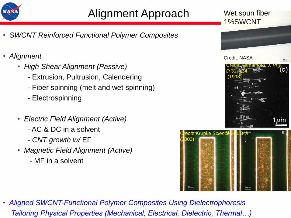
• SWCNT Reinforced Functional Polymer Composites
• Alignment
• High Shear Alignment (Passive)
- Extrusion, Pultrusion, Calendering
- Fiber spinning (melt and wet spinning)
- Electrospinning
• Electric Field Alignment (Active)
- AC & DC in a solvent
- CNT growth w/ EF
• Magnetic Field Alignment (Active)
- MF in a solvent
• Aligned SWCNT-Functional Polymer Composites Using Dielectrophoresis
Tailoring Physical Properties (Mechanical, Electrical, Dielectric, Thermal…)
Alignment Approach Wet spun fiber
1%SWCNT
Credit: Yamamoto, J. Phy.
D 31, L34
(1998)
Credit: Krupke Science 301 344
(2003)
Credit: NASA
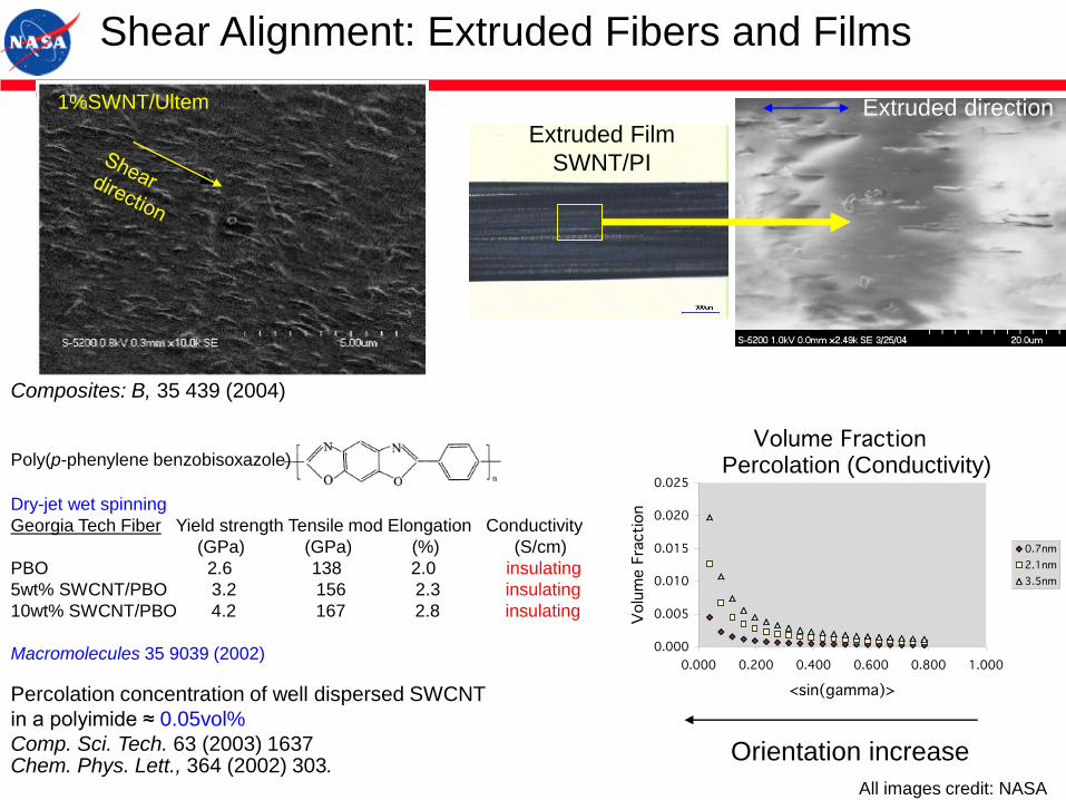
Shear Alignment: Extruded Fibers and Films
Composites: B, 35 439 (2004)
1%SWNT/Ultem
Dry-jet wet spinning
Georgia Tech Fiber Yield strength Tensile mod Elongation Conductivity
(GPa) (GPa) (%) (S/cm)
PBO 2.6 138 2.0 insulating
5wt% SWCNT/PBO 3.2 156 2.3 insulating
10wt% SWCNT/PBO 4.2 167 2.8 insulating
Macromolecules 35 9039 (2002)
Percolation (Conductivity)
Extruded directionExtruded Film
SWNT/PI
Percolation concentration of well dispersed SWCNT
in a polyimide ≈ 0.05vol%
Comp. Sci. Tech. 63 (2003) 1637Chem. Phys. Lett., 364 (2002) 303.
Orientation increase
Poly(p-phenylene benzobisoxazole)
All images credit: NASA

l =pe0e1a
3(bE)2
kBT
Dielectrophoretic Alignment: Spheres, Platelets, Fibers…
AC Electric Field Alignment
Davis, J. Appl. Phys. 72, 1334 (1992)
Park and Robertson, J. Mater. Sci., 33, 3541 (1998)
Images Credit: Park and Robertson, Mater. Sci. Eng., A257, 295 (1998)
Spheres Fibers
b = (1) or (ssss1)
Model for longitudinal and lateral
aggregation of inclusions
> 1 for Alignment
100µm 100µm
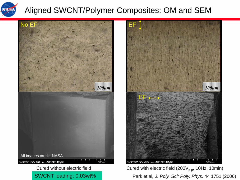
Aligned SWCNT/Polymer Composites: OM and SEM
Cured without electric field Cured with electric field (200Vp-p, 10Hz, 10min)
EFNo EF
Park et al, J. Poly. Sci: Poly. Phys. 44 1751 (2006)
EF
SWCNT loading: 0.03wt%
All images credit: NASA
10-15
10-13
10-11
10-9
10-7
10-5
0.001 0.1 10 1000 105 107
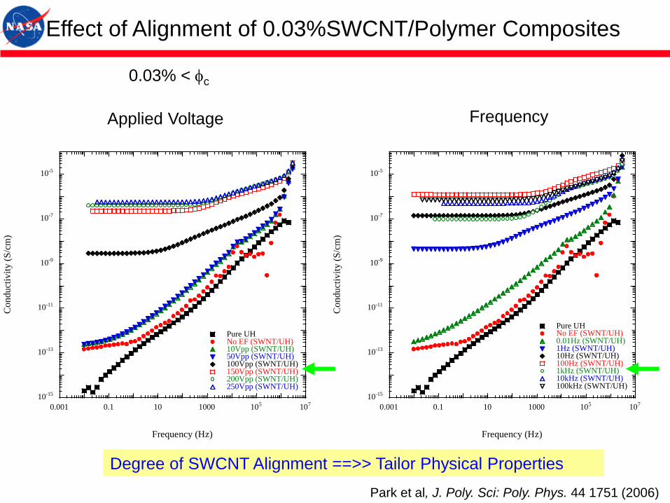
Pure UHNo EF (SWNT/UH)0.01Hz (SWNT/UH)1Hz (SWNT/UH)10Hz (SWNT/UH)100Hz (SWNT/UH)1kHz (SWNT/UH)10kHz (SWNT/UH)100kHz (SWNT/UH)
Co
ndu
ctiv
ity
(S
/cm
)
Frequency (Hz)
Effect of Alignment of 0.03%SWCNT/Polymer Composites
10-15
10-13
10-11
10-9
10-7
10-5
0.001 0.1 10 1000 105 107
Pure UHNo EF (SWNT/UH)10Vpp (SWNT/UH)50Vpp (SWNT/UH)100Vpp (SWNT/UH)150Vpp (SWNT/UH)200Vpp (SWNT/UH)250Vpp (SWNT/UH)
Co
ndu
ctiv
ity
(S
/cm
)
Frequency (Hz)
Applied Voltage Frequency
0.03% < fc
Park et al, J. Poly. Sci: Poly. Phys. 44 1751 (2006)
Degree of SWCNT Alignment ==>> Tailor Physical Properties
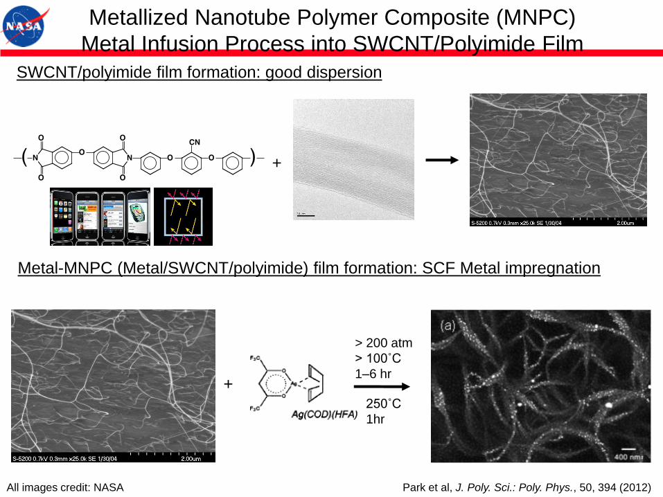
+
+
> 200 atm
> 100˚C
1–6 hr
250˚C
1hr
Metallized Nanotube Polymer Composite (MNPC)
Metal Infusion Process into SWCNT/Polyimide Film
SWCNT/polyimide film formation: good dispersion
Metal-MNPC (Metal/SWCNT/polyimide) film formation: SCF Metal impregnation
Park et al, J. Poly. Sci.: Poly. Phys., 50, 394 (2012) All images credit: NASA

Ag-MNPC Films with various SWCNT Concentration
0.1%SWCNT
0%SWCNT
2%SWCNT
10%SWCNT
Control Ag-MNPC
Shiny surfaces
Reflection shielding
Park et al, J. Poly. Sci.: Poly. Phys., 50, 394 (2012) All images credit: NASA
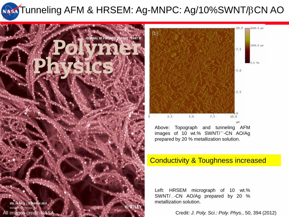
Above: Topograph and tunneling AFM
images of 10 wt.% SWNT/ -CN AO/Ag
prepared by 20 % metallization solution.
Tunneling AFM & HRSEM: Ag-MNPC: Ag/10%SWNT/bCN AO
Left: HRSEM micrograph of 10 wt.%
SWNT/ -CN AO/Ag prepared by 20 %
metallization solution.
Conductivity & Toughness increased
Credit: J. Poly. Sci.: Poly. Phys., 50, 394 (2012) All images credit: NASA
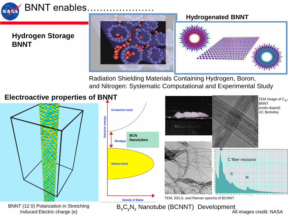
Hydrogen Storage
BNNT
Hydrogenated BNNT
BNNT enables…………………
B
CN
C fiber resource
TEM, EELS, and Raman spectra of BCNNT.
BCN
Nanotubes
TEM image of C60-
BNNT
(endo-doped)
UC Berkeley
BxCyNz Nanotube (BCNNT) Development
Radiation Shielding Materials Containing Hydrogen, Boron,
and Nitrogen: Systematic Computational and Experimental Study
Electroactive properties of BNNT
BNNT (12 0) Polarization in Stretching
Induced Electric charge (e) All images credit: NASA
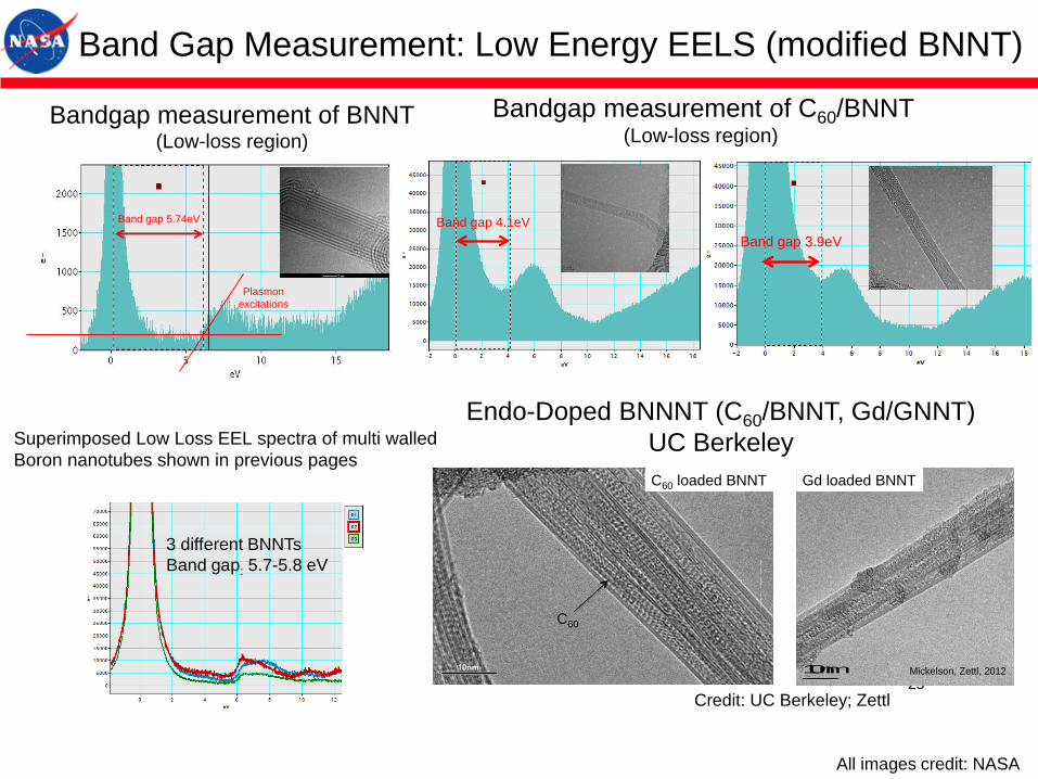
Bandgap measurement of BNNT (Low-loss region)
Band gap 5.74eV
Plasmon
excitations
Superimposed Low Loss EEL spectra of multi walled
Boron nanotubes shown in previous pages
3 different BNNTs
Band gap: 5.7-5.8 eV
Band gap 4.1eV
Bandgap measurement of C60/BNNT(Low-loss region)
Band gap 3.9eV
25
10nm
C60
C60 loaded BNNT
Gd@C82 loaded into BNNTs
Mickelson, Zettl, 2012 10 nm
Gd loaded BNNT
Mickelson, Zettl, 2012
Endo-Doped BNNNT (C60/BNNT, Gd/GNNT)
UC Berkeley
Band Gap Measurement: Low Energy EELS (modified BNNT)
All images credit: NASA
Credit: UC Berkeley; Zettl

Doped Chiral Polymer Metamaterials
(DCPM)
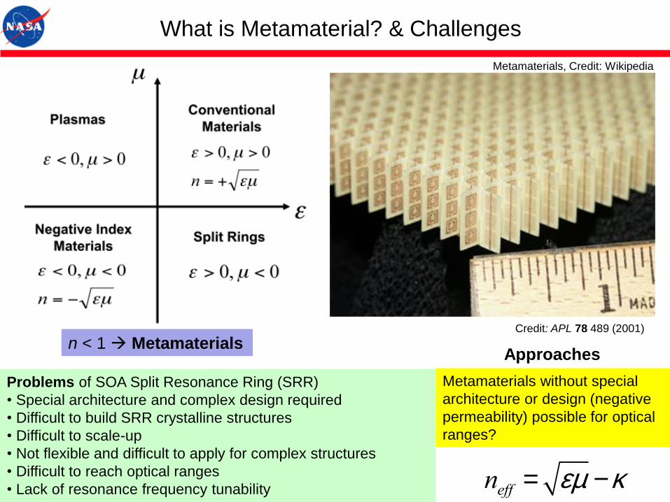
Problems of SOA Split Resonance Ring (SRR)
• Special architecture and complex design required
• Difficult to build SRR crystalline structures
• Difficult to scale-up
• Not flexible and difficult to apply for complex structures
• Difficult to reach optical ranges
• Lack of resonance frequency tunability
What is Metamaterial? & Challenges
n < 1 Metamaterials
neff = em -k
Metamaterials without special
architecture or design (negative
permeability) possible for optical
ranges?
Approaches
Credit: APL 78 489 (2001)
Metamaterials, Credit: Wikipedia
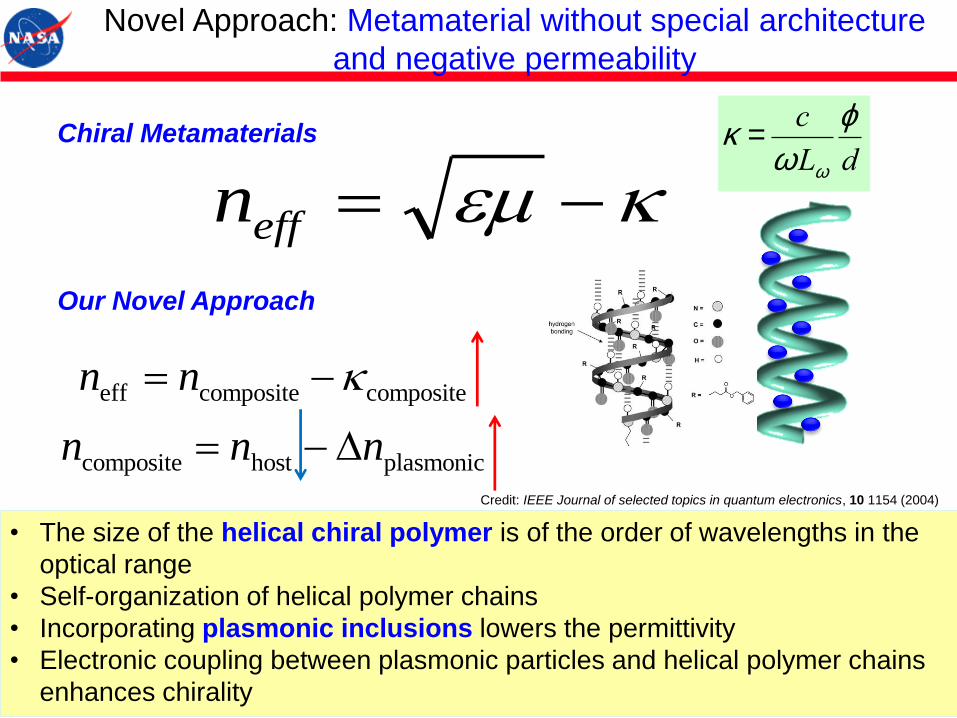
Our Novel Approach
eff composite composite
composite host plasmonic
n n
n n n
D
André Knoesen et al, “Sum-frequency spectroscopy and imaging of aligned helical polypeptides”, IEEE J in quantum electronics, 10 (5), 1154, 2004
• The size of the helical chiral polymer is of the order of wavelengths in the
optical range
• Self-organization of helical polymer chains
• Incorporating plasmonic inclusions lowers the permittivity
• Electronic coupling between plasmonic particles and helical polymer chains
enhances chirality
effn
Chiral Metamaterials
Novel Approach: Metamaterial without special architecture
and negative permeability
Poly-γ-benzyl-L-glutamate (PBLG) Helical handedness of PBLG
α-helix structure of poly-γ-benzyl-L-glutamate
(PBLG)
A. ELLIOTT, W. E. HANBY & B. R. MALCOLM, “Optical Rotation of the α -Helix in Synthetic Polypeptides,” Nature, 178, 1956,1170.
“ In a later communication, they have concluded from the change in
specific rotation on destruction of the α -helix (in poly--benzyl-L-glutamate
and in poly-L-glutamic acid) that in these polymers the helices are right-
handed….”
Credit: IEEE Journal of selected topics in quantum electronics, 10 1154 (2004)
k =c
vLv
j
d
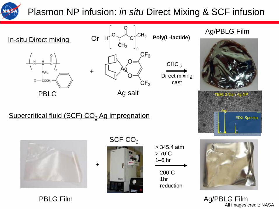
Plasmon NP infusion: in situ Direct Mixing & SCF infusion
+
+
> 345.4 atm
> 70˚C
1–6 hr
200˚C
1hr
reduction
In-situ Direct mixing
Supercritical fluid (SCF) CO2 Ag impregnation
CHCl3
PBLG Ag salt
Ag/PBLG Film
Direct mixing
cast
SCF CO2
PBLG Film Ag/PBLG Film
TEM: 3-5nm Ag NP
EDX Spectra
Ag
Poly(L-lactide)Or
All images credit: NASA
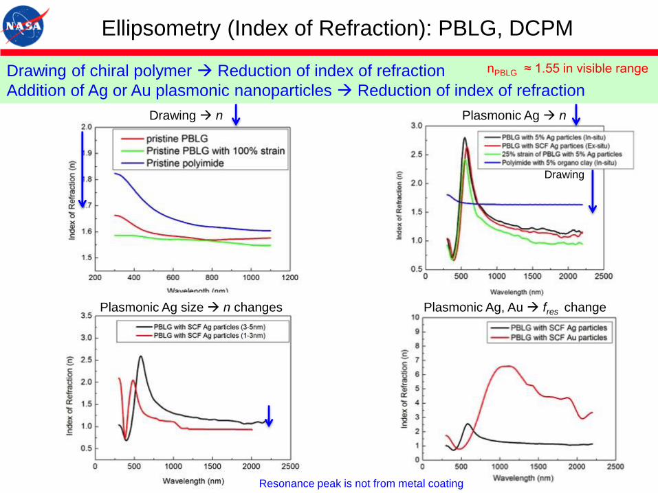
Plasmonic Ag n
Drawing
Drawing n
Plasmonic Ag size n changes Plasmonic Ag, Au fres change
Ellipsometry (Index of Refraction): PBLG, DCPM
Drawing of chiral polymer Reduction of index of refraction
Addition of Ag or Au plasmonic nanoparticles Reduction of index of refraction
Resonance peak is not from metal coating
nPBLG ≈ 1.55 in visible range
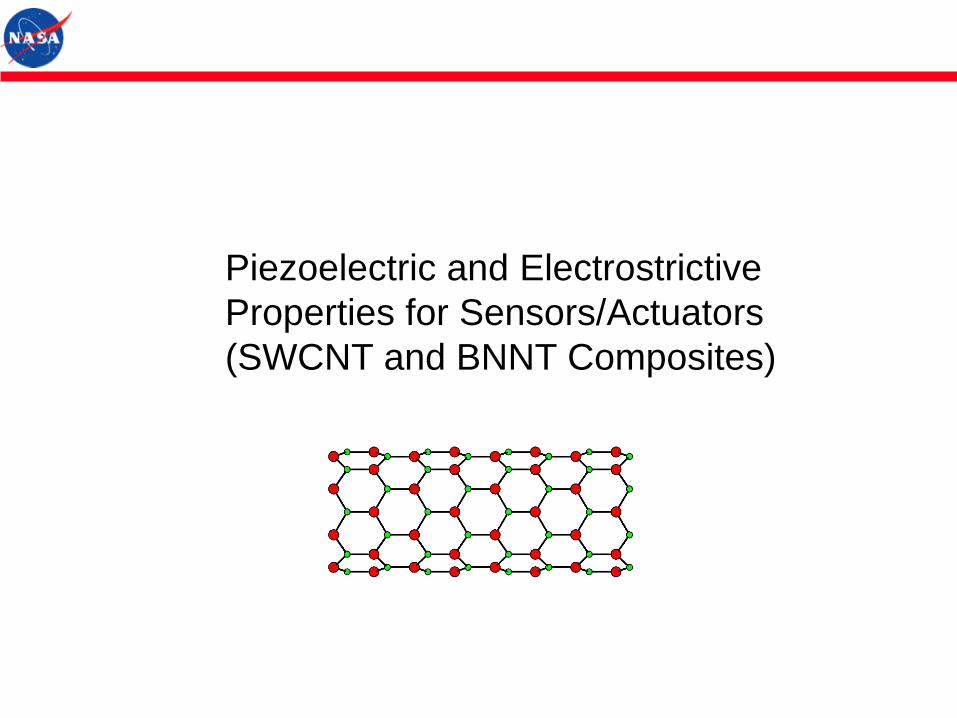
Piezoelectric and Electrostrictive
Properties for Sensors/Actuators
(SWCNT and BNNT Composites)
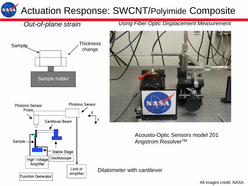
Actuation Response: SWCNT/Polyimide CompositeUsing Fiber Optic Displacement Measurement
Acousto-Optic Sensors model 201
Angstrom ResolverTM
Out-of-plane strain
Sample holder
Thickness
changeSample
Dilatometer with cantilever
All images credit: NASA

0
0.005
0.01
0.015
0.02
0.025
0.03
0 0.5 1 1.5 2
0% SWNT0.02% SWNT0.035% SWNT0.05% SWNT0.1% SWNT0.2% SWNT
Neg
ativ
e o
ut-
of-
pla
ne
stra
in (–
e 33)
Electric field (MV/m)
Electrostrictive coefficient
SWCNT/Polyimide M33 = -3.6 x 10⁻¹⁵ ~ -1.2 x 10⁻¹³ m2/V2
Polyurethane M33 = -4.6 x 10⁻¹⁸ ~ -1.6 x 10⁻¹⁷ m2/V2
103 – 104 times higher S33 = SE (Electrostriction)
+ SM (Maxwell effect)
< 0.01%)21(2
1 2
0 nee +-= EY
S rM
2.6% at 0.8 MV/m
Actuation: Out-of Plane Strain: SWCNT Polymer Composite
Park et al, Adv Mater, 20 2074 (2008)
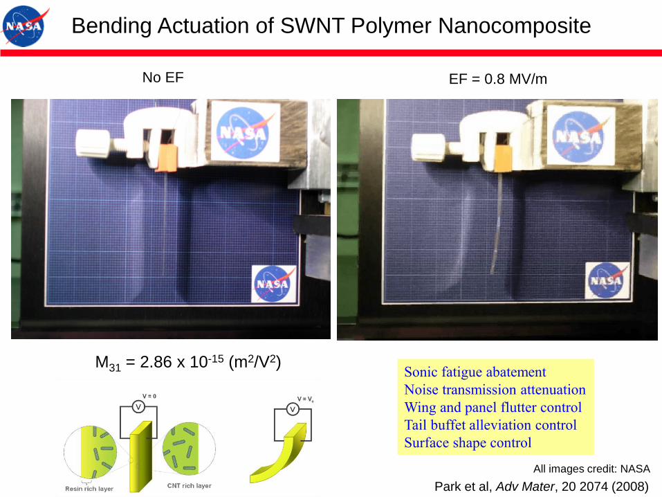
Bending Actuation of SWNT Polymer Nanocomposite
No EF EF = 0.8 MV/m
M31 = 2.86 x 10⁻¹⁵ (m2/V2)Sonic fatigue abatement
Noise transmission attenuation
Wing and panel flutter control
Tail buffet alleviation control
Surface shape control
Park et al, Adv Mater, 20 2074 (2008)
All images credit: NASA
Multifunctional BNNT Polymer Composites
• Electroactive Properties
• Radiation Shielding Properties
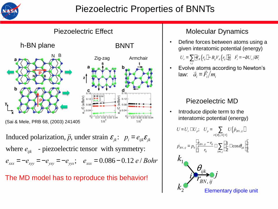
Piezoelectric Properties of BNNTs
The MD model has to reproduce this behavior!
(Sai & Mele, PRB 68, (2003) 241405)
BN
h-BN plane BNNT
Zig-zag Armchair
Induced polarization, p, under strain e jk : pi = eijke jk
where eijk - piezoelectric tensor with symmetry:
exxx = -exyy = -eyxy = -eyyx; exxx = 0.086 - 0.12 e / Bohr
Molecular Dynamics
• Define forces between atoms using a
given interatomic potential (energy)
• Evolve atoms according to Newton’s
law:
Ur = VR rij( ) -BijVA rij( )éë
ùû
i, j
å ; Fi = -¶Ur ¶ri
ai = Fi mi
Piezoelectric MD
• Introduce dipole term to the
interatomic potential (energy)
U =Ur +Up; Up = U pBN , ij( )i= B{ }, j= N{ }
å
pBN , ij = p0
rBN , ij - r0
r0+
1
2+ cosqijk
æ
èç
ö
ø÷
k¹i, j
åé
ëêê
ù
ûúú
rBN , ij
qijk ji
k1
k2 Elementary dipole unit
Piezoelectric Effect
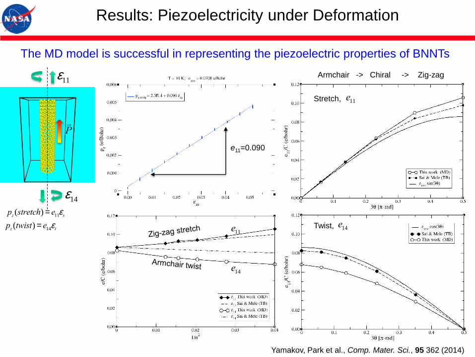
Results: Piezoelectricity under Deformation
e11
e14
Armchair -> Chiral -> Zig-zag
Twist,
Stretch,
e11=0.090
e11
e14
The MD model is successful in representing the piezoelectric properties of BNNTs
pz (stretch) = e11es
pz (twist) = e14et
P
e14
e11
Yamakov, Park et al., Comp. Mater. Sci., 95 362 (2014)
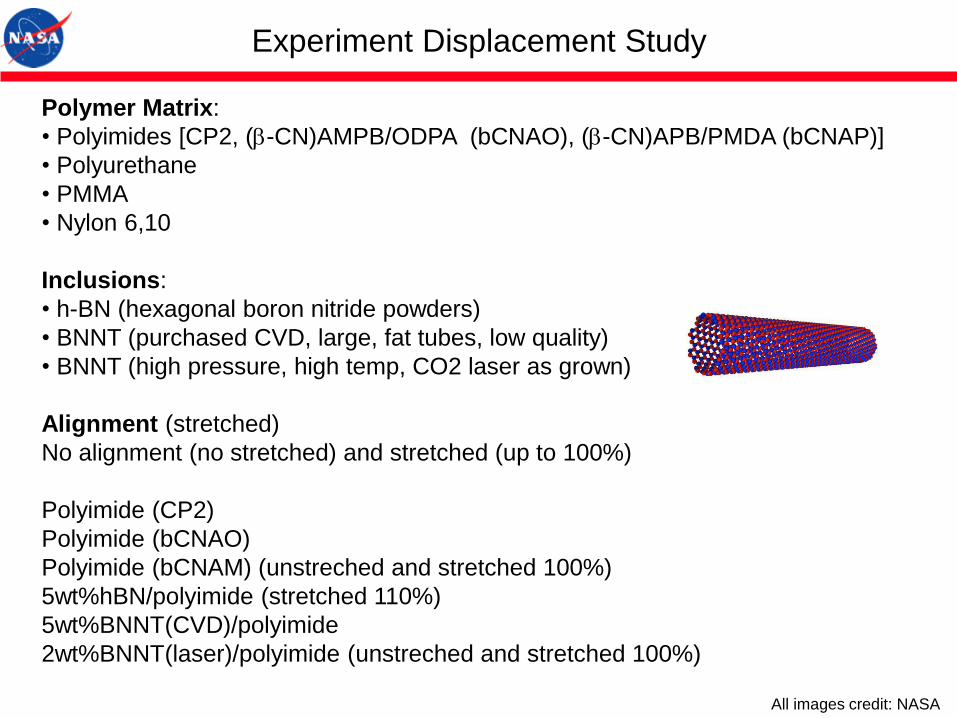
Experiment Displacement Study
Polymer Matrix:
• Polyimides [CP2, (b-CN)AMPB/ODPA (bCNAO), (b-CN)APB/PMDA (bCNAP)]
• Polyurethane
• PMMA
• Nylon 6,10
Inclusions:
• h-BN (hexagonal boron nitride powders)
• BNNT (purchased CVD, large, fat tubes, low quality)
• BNNT (high pressure, high temp, CO2 laser as grown)
Alignment (stretched)
No alignment (no stretched) and stretched (up to 100%)
Polyimide (CP2)
Polyimide (bCNAO)
Polyimide (bCNAM) (unstreched and stretched 100%)
5wt%hBN/polyimide (stretched 110%)
5wt%BNNT(CVD)/polyimide
2wt%BNNT(laser)/polyimide (unstreched and stretched 100%)
All images credit: NASA

Study of Origin of Actuation: Stretched Films
Actuation of Unstretched/Stretched Pristine Polyimide
Unstretched100% Stretched
@225oC, Annealing
Pristine and composite films
are stretched with a tensile
tester (Instron microtest) in
an oven at above Tg
33 = d33·E + M33·E2 + …
Field induced strain (33)
d33: piezoelectric (PE)
M33: mostly electrostrictive (ES)
All images credit: NASA

Stretched BNNT-Polyimide Nanocomposite
100 % Strain,
225C slightly above Tg
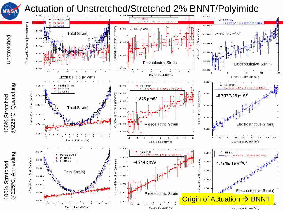
Actuation of Unstretched/Stretched 2% BNNT/PolyimideU
nstr
etc
hed
10
0%
Str
etc
he
d
@2
25
oC
, A
nn
ea
ling
10
0%
Str
etc
he
d
@2
25
oC
, Q
ue
nch
ing
Origin of Actuation BNNT
Out –
of-
Str
ain
(m
m/m
m)
Electric Field (MV/m)
Piezoelectric Strain
Piezoelectric Strain
Piezoelectric Strain
Electrostrictive Strain)
Electrostrictive Strain)
Electrostrictive Strain)
Total Strain)
Total Strain)
Total Strain)
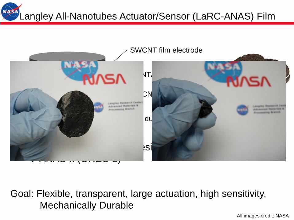
Langley All-Nanotubes Actuator/Sensor (LaRC-ANAS) Film
SWCNT film electrode
SWCNT film electrode
BNNT/Polymer active layer
Infiltration of elastomeric resin into ANAS
ANAS-II (OREO 2)
LaRC ANAS-I shows low mechanical durability to be applied to actual
applications
Goal: Flexible, transparent, large actuation, high sensitivity,
Mechanically DurableAll images credit: NASA
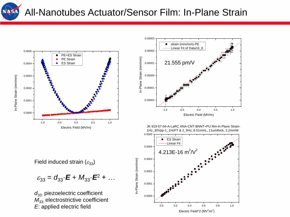
All-Nanotubes Actuator/Sensor Film: In-Plane Strain
-1.0 -0.5 0.0 0.5 1.0
0.0000
0.0001
0.0002
0.0003
0.0004
0.0005
PE+ES Strain
PE Strain
ES Strain
In-P
lan
e S
tra
in (
mm
/mm
)
Electric Field (MV/m)
-1.0 -0.5 0.0 0.5 1.0
-0.00002
-0.00001
0.00000
0.00001
0.00002
0.00003
21.555 pm/V
strain (mm/mm)-PE
Linear Fit of Data16_E
In-P
lan
e S
tra
in (
mm
/mm
)
Electric Field (MV/m)
0.0 0.2 0.4 0.6 0.8 1.0
0.0000
0.0001
0.0002
0.0003
0.0004
0.0005
JK 919-57-04-A-LaRC ANA-CNT-BNNT+PU film-In Plane Strain-
1Hz_30Vpp-1_1HzFT & 2_5Hz, 9.51mmL, 11umthick, 2.2mmW
ES Strain
Linear Fit
4.213E-16 m2/V
2
In-P
lan
e S
tra
in (
mm
/mm
)
Electric Field^2 (MV2/m
2)
33 = d33·E + M33·E2 + …
Field induced strain (33)
d33: piezoelectric coefficient
M33: electrostrictive coefficient
E: applied electric field
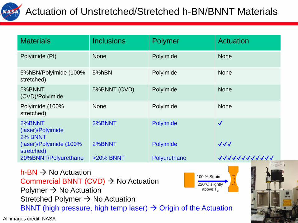
Materials Inclusions Polymer Actuation
Polyimide (PI) None Polyimide None
5%hBN/Polyimide (100%
stretched)
5%hBN Polyimide None
5%BNNT
(CVD)/Polyimide
5%BNNT (CVD) Polyimide None
Polyimide (100%
stretched)
None Polyimide None
2%BNNT
(laser)/Polyimide
2% BNNT
(laser)/Polyimide (100%
stretched)
20%BNNT/Polyurethane
2%BNNT
2%BNNT
>20% BNNT
Polyimide
Polyimide
Polyurethane
✔
✔✔✔
✔✔✔✔✔✔✔✔✔✔✔✔
Actuation of Unstretched/Stretched h-BN/BNNT Materials
h-BN No Actuation
Commercial BNNT (CVD) No Actuation
Polymer No Actuation
Stretched Polymer No Actuation
BNNT (high pressure, high temp laser) Origin of the Actuation
100 % Strain
220C slightly
above Tg
All images credit: NASA
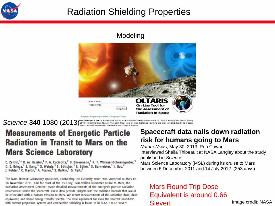
Radiation Shielding Properties
Modeling
Science 340 1080 (2013)
Spacecraft data nails down radiation
risk for humans going to MarsNature News, May 30, 2013, Ron Cowan
Interviewed Sheila Thibeault at NASA Langley about the study
published in Science
Mars Science Laboratory (MSL) during its cruise to Mars
between 6 December 2011 and 14 July 2012 (253 days)
Mars Round Trip Dose
Equivalent is around 0.66
Sievert Image credit: NASA
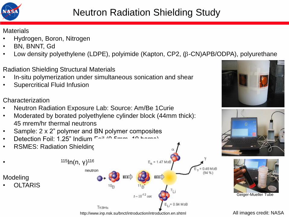
Neutron Radiation Shielding Study
Materials
• Hydrogen, Boron, Nitrogen
• BN, BNNT, Gd
• Low density polyethylene (LDPE), polyimide (Kapton, CP2, (b-CN)APB/ODPA), polyurethane
Radiation Shielding Structural Materials
• In-situ polymerization under simultaneous sonication and shear
• Supercritical Fluid Infusion
Characterization
• Neutron Radiation Exposure Lab: Source: Am/Be 1Curie
• Moderated by borated polyethylene cylinder block (44mm thick):
45 mrem/hr thermal neutrons
• Sample: 2 x 2” polymer and BN polymer composites
• Detection Foil: 1.25” Indium Foil (0.5mm, 19 barns)
• RSMES: Radiation Shielding Materials Evaluation Software
• 115In(n, γ)116In
Modeling
• OLTARIS
http://www.inp.nsk.su/bnct/introduction/introduction.en.shtml
neutron
Geiger-Mueller Tube
All images credit: NASA

Advanced Radiation Shielding Materials Containing
Hydrogen, Boron, and Nitrogen: Preliminary Results
Beta radiationNeutron radiation
Am/Be 1Curie & moderated by borated PE 0.1 μCi Sr-90: β (Synthesized Apr 2009)

State of Art
Less Dosage
Is BetterMaterials assumed
to have common
30 cm thickness.
BN materials perform better than LH2 and water.
BN+5%H performs better than state of art polyethylene.
Dose Equivalent of Various
Shielding Materials: OLTARIS Modeling: GCR 1997
GCR: Galactic Cosmic Rays
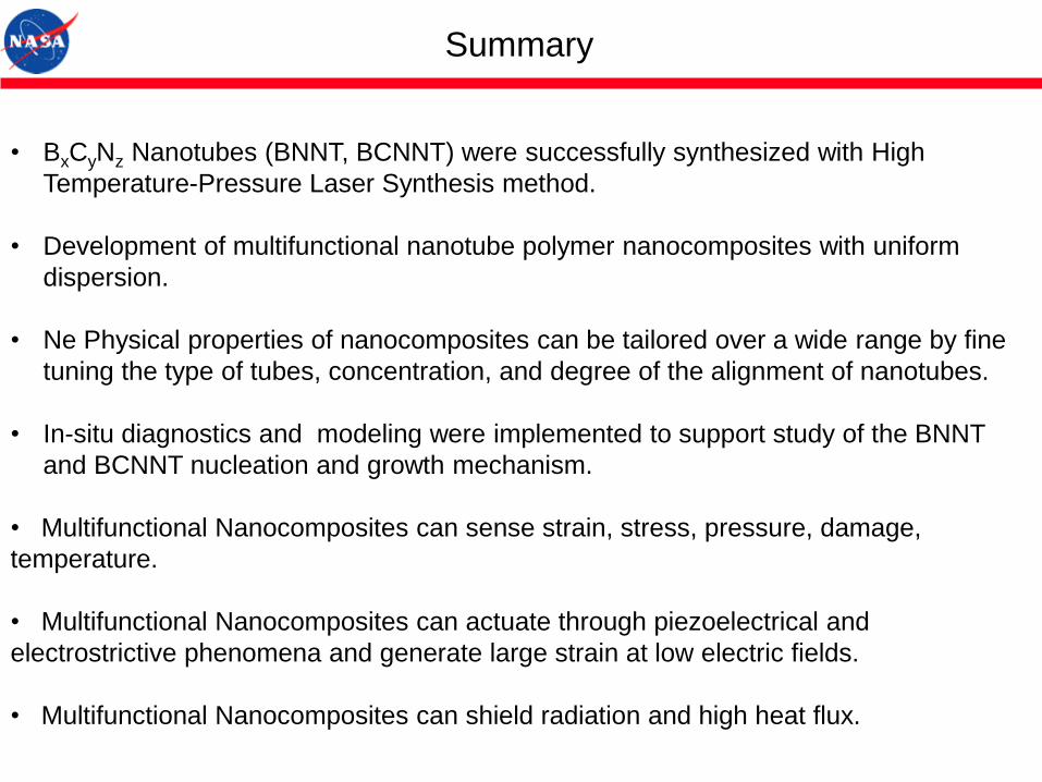
Summary
• BxCyNz Nanotubes (BNNT, BCNNT) were successfully synthesized with High
Temperature-Pressure Laser Synthesis method.
• Development of multifunctional nanotube polymer nanocomposites with uniform
dispersion.
• Ne Physical properties of nanocomposites can be tailored over a wide range by fine
tuning the type of tubes, concentration, and degree of the alignment of nanotubes.
• In-situ diagnostics and modeling were implemented to support study of the BNNT
and BCNNT nucleation and growth mechanism.
• Multifunctional Nanocomposites can sense strain, stress, pressure, damage,
temperature.
• Multifunctional Nanocomposites can actuate through piezoelectrical and
electrostrictive phenomena and generate large strain at low electric fields.
• Multifunctional Nanocomposites can shield radiation and high heat flux.

Thank You
All Images Credit: NASA


![Aerospace Science and Technologyasdr.eng.ua.edu/doc/pdf/j/2018_AST_79_297.pdf · Aerospace Scienceand Technology 79 (2018) 297–309 ... multifunctional structural technologies [8]may](https://img.pdfslide.us/doc/110x75/5ecb67b5c757de52494be152/aerospace-science-and-aerospace-scienceand-technology-79-2018-297a309-multifunctional.jpg)