Embed Size (px)
Citation preview

INSTALLATION and SERVICE INSTRUCTIONSUSE and CARE INSTRUCTIONS
distributed by
DèLonghiPty Ltd
MULTIFUNCTIONBUILT-IN OVENS

2
Dear Customer,
Thank you for having purchased and given yourpreference to our product.
The safety precautions and recommendations reportedbelow are for your own safety and that of others. Theywill also provide a means by which to make full use ofthe features offered by your appliance.
Please keep this booklet in a safe place. It may beuseful in future, either to yourself or to others in theevent that doubts should arise relating to its operation.
This appliance must be used only for the task it hasexplicitly been designed for, that is for cookingfoodstuffs. Any other form of usage is to be consideredas inappropriate and therefore dangerous.
The manufacturer declines all responsibility in theevent of damage caused by improper, incorrect orillogical use of the appliance or be faulty installation.
PRODUCT LABEL
This oven has been designed and constructed in accordance with the following codesand specifications:
AS/NZS 60335-1 General Requirements for Domestic electrical appliances
AS/NZS 60335-2-6 Particular Requirements for Domestic electrical cooking appliances
AS/NSZ 1044 Electromagnetic Compatibility Requirements.

3
IMPORTANT PRECAUTIONS AND RECOMMENDATIONS FORUSE OF ELECTRICAL APPLIANCES
Use of any electrical appliance implies the necessity to follow a series of fundamentalrules. In particular:
■ Never touch the appliance with wet hands or feet;
■ Do not operate the appliance barefooted;
■ The appliance is not intended for use by young children or infirm personswithout supervision;
■ Young children should be supervised to ensure they do not play with theappliance.
The manufacturer cannot be held responsible for any damages caused by improper,incorrect or illogical use of the appliance.
CONTENTS
Precautions and recommendations ................................................” 3 -4
Installation......................................................................................” 5
Use and care .................................................................................” 12Cooking with multifunction oven ...............................................” 16Electronic programmer ...............................................................” 22Cut-off timer ...............................................................................” 27
Cleaning and maintenance............................................................” 28
USING THE OVEN FOR THE FIRST TIMEYou are advised to carry out the following operations:
■ Furnish the interior of the oven.■ Switch the empty oven ON at maximum temperature for about two hours to
eliminate traces of grease and smell from the components.■ Disconnect the appliance from the electric power supply and clean the
interior of the oven with a cloth soaked in water and neutral detergent anddry thoroughly.

4
IMPORTANT PRECAUTIONS AND RECOMMENDATIONSAfter having unpacked the appliance, check to ensure that it is not damaged.In case of doubt, do not use it and consult your supplier or a professionally qualified technician.Packing elements (i.e. plastic bags, polystyrene foam, nails, packing straps, etc.) should not beleft around within easy reach of children, as these may cause serious injuries.■ Do not attempt to modify the technical characteristics of the appliance as this may become
dangerous to use.■ Do not carry out cleaning or maintenance operations on the appliance without having pre-
viously disconnected it from the electric power supply.■ After use, ensure that the knobs are in the off position.
■ The appliance is not intended for use by young children or infirm persons unless they have beenadequately supervised by a responsible person to ensure that they can use the appliance safely.
■ During and after use of the appliance, certain parts will become very hot. Do not touch hotparts. Care should be taken to avoid touching heating elements inside the oven.
■ Keep children away from the appliance when it is in use.
■ Young children should be supervised to ensure that they do not play with the appliance.
■ Some appliances are supplied with a protective film on steel and aluminium parts. This filmmust be removed before using the appliance.
■ Make sure that electrical cables connecting other appliances in the proximity of the oven donot become entrapped in the oven door.
■ Do not line the oven walls with aluminium foil. Do not place baking trays or the drip trayon the base of the oven chamber.
■ WARNING When correctly installed, your product meets all safety requirements laid downfor this type of product category. However special care should be taken around the rear orthe underneath of the appliance as these areas are not designed or intended to be touchedand may contain sharp or rough edges, that may cause injury.
■ Fire risk! Do not store flammable material in the oven.■ Always use oven gloves when removing the shelves and food trays from the oven whilst hot.
■ Do not hang towels, dishcloths or other items on the appliance or its handle – as this couldbe a fire hazard.
■ Clean the oven regularly and do not allow fat or oils to build up in the oven base or tray.Remove spillages as soon as they occur.
■ Do not stand on the open oven door.
■ Always stand back from the appliance when opening the oven door to allow steam and hotair to escape before removing the food.
■ This appliance is for domestic use only.
■ Safe food handling: leave food in the oven for as short a time as possible before and aftercooking. This is to avoid contamination by organisms which may cause food poisoning. Takeparticular care during warmer weather.
■ The manufacturer declines all liability for injury to persons or damage to property caused byincorrect or improper use of the appliance.
■ WARNING: Taking care NOT to lift the oven by the door handle.
■ IMPORTANT NOTE: This appliance shall not be used as a space heater,especially if installed in marine craft or caravans.

5
INSTALLATION
CAUTION:■ This appliance must be installed in accordance with these installation
instructions. ■ This appliance shall only be serviced by authorized personnel.■ This appliance is to be installed only by an authorised person. ■ Incorrect installation, for which the manufacturer accepts no responsibil-
ity, may cause personal injury of damage. ■ Always disconnect the oven from mains power supply before carrying
out any maintenance operations or repairs.
N.B. • The connection of the appliance to earth is mandatory. • For connection to the mains, do not use adapters, reducers or
branching devices as they can cause overheating and burning.
If the installation requires alterations to the domestic electrical system call a qualifiedelectrician. He should also check that the socket cable section is suitable for the powerdrawn by the appliance.
ELECTRICAL REQUIREMENTS
■ The oven is supplied without a power supply plug and therefore if you arenot connecting directly to the mains, a standardized plug suitable for theload must be fitted.
■ Connection to the mains must be carried out by qualified personnel inaccordance with current regulations.
■ The appliance must be connected to the mains checking that the voltagecorresponds to the value given in the rating plate and that the electricalcable sections can withstand the load specified on the plate.
■ The plug must be connected to an earthed socket in compliance with safetystandards.
■ The appliance must be connected directly to the mains placing a two poleswitch with minimum opening between the contacts of 3 mm between theappliance and the mains.
■ The power supply cable must not touch the hot parts and must bepositioned so that it does not exceed 75°C at any point.
■ Once the appliance has been installed, the switch or socket must always beaccessible.
■ If the supply cord is damaged it must be replaced by themanufacturer or its Service Agent or a similarly qualified person inorder to avoid a hazard.

6
REPAIRSREPLACING THE POWER SUPPLY CABLE
■ Unhook the terminal board cover by inserting a screwdriver into the twohooks A (fig. 2).
■ Open the cable gland by unscrewing screw F (fig. 3), unscrew the terminalscrews and remove the cable.
■ The new supply cable, of suitable type and section, is connected to theterminal board following the diagram fig. 1.
FEEDER CABLE SECTION TYPE HO5RR-F
A
F
230 - 240 V
E
NL1 (L )2
Figure 2 Figure 3
Figure 1
230 V~ 2350 W (10,2 A) 3 x 1,5 mm2
240 V~ 2550 W (10,6 A) 3 x 1,5 mm2

7
S1S2
F1PR
1
6
1a
6a
4
9
4a
9a
3
8
3a
8a
2
7
2a
7a
5
10
11
5a
10a
11a
C
G
S
V
CIR
TM
CF
N/7
1
1a
L/8
LF1
TL
T
NLM
LF2
ELECTRIC DIAGRAM - multifunction OVENS(models with electronic programmer)
Figure 4
F1 Oven switchTM Oven thermostatTL Thermal overloadPR Electronic programmerLF1 Oven lampLF2 Oven lampS1 Thermostat pilot lampS2 Line pilot lampC Top elementG Grill elementS Bottom elementV FanCIR Circular elementCF Cooling fanM Terminal blockT Earth connection

8
ELECTRIC DIAGRAM - multifunction OVENS(models with cut-off timer)
Figure 5
F1 Oven switchTM Oven thermostatLF Oven lampCC Oven cut-offS1 Line pilot lampS2 Thermostat pilot lampTL Thermal overloadM Terminal blockC Top elementG Grill elementS Bottom elementCIR Circular elementCF Cooling fanV FanT Earth connection

9
FITTING THE OVEN INTO ABASEThe space available should be of thedimensions shown in the figure 6.Arrangements should be made for anadequate supply of the air to the ovento avoid overheating (fig. 7).
560
550 min
591
594
594
540
20
536 min
600
The walls surroundingthe oven must bemade of heat-resistantmaterial. Both theveneered plastic andthe adhesive usedmust be resistant totemperatures of 120°Cin order to preventunsticking and defor-mation.
FITTING REQUIREMENTSWARNING: Taking care NOT to lift the oven by the door handle.
The oven must be built-in in a standard module of furniture of 60 cm width anddepth. It is to be fit up in a module having the clearance as shown in the pictures. On the lower side, the oven must lay on supports standing the oven weight. The ovens are secured by four screws that pass through the surround. They must locate firmly and squarely in the edges of the cabinet or add panels toachieve a secure location.
Figure 6
Figure 7

10
560
50
585
FITTING THE OVEN INTO ACOLUMNThe cabinet should have the dimensions asper fig. 8.Furthermore it is necessary that the oven isprovided with a chimney as per fig. 9.If the column unit reaches the ceiling anoutlet must be provided through which aircan flow to the outside
� �
50 mm
50 550
Figure 8
Figure 9
WARNINGWhen correctly installed, your product meets all safety requirements laiddown for this type of product category.However special care should be taken around the rear or the underneathof the appliance as these areas are not designed or intended to be touchedand may contain sharp or rough edges, that may cause injury.

11
OVEN DOOR
LOWER TRIM
AIR FLOW
IMPORTANT:Please take extra care not to damage the lower trim of the oven.
Ensure the oven sits on wooden blocks or similar supports when it is removed fromthe carton as shown in above diagram. This will prevent any damage to the lowertrim.
Should the lower trim become damaged, straighten the trim and ensure the ovendoor opens fully without obstruction from the lower trim.
After installation check the lower trim is still undamaged.
The space between the bottom of the door & the lower trim is important to allowproper air circulation into the oven.
The oven door should be opened slowly to it’s fully open position ensuring there isadequate clearance between the bottom of the door and the lower trim.
The manufacturer does not accept responsibility for any damage to the ovenresulting from incorrect installation.
Figure 10
12
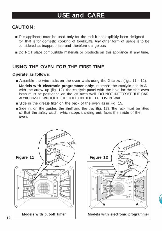
CAUTION:
■ This appliance must be used only for the task it has explicitly been designedfor, that is for domestic cooking of foodstuffs. Any other form of usage is to beconsidered as inappropriate and therefore dangerous.
■ Do NOT place combustible materials or products on this appliance at any time.
USING THE OVEN FOR THE FIRST TIME
Operate as follows:
■ Assemble the wire racks on the oven walls using the 2 screws (figs. 11 - 12).Models with electronic programmer only: interpose the catalytic panels Awith the arrow up (fig. 12); the catalytic panel with the hole for the side ovenlamp must be positioned on the left oven wall. DO NOT INTERPOSE THE CAT-ALYTIC PANEL WITHOUT THE HOLE ON THE LEFT OVEN WALL.
■ Slide in the grease filter on the back of the oven as in Fig. 15.■ Slide in, on the guides, the shelf and the tray (fig. 13). The rack must be fitted
so that the safety catch, which stops it sliding out, faces the inside of theoven.
USE and CARE
Figure 11 Figure 12
A A
Models with electronic programmerModels with cut-off timer

13
■ To eliminate traces of grease inmanufacture it is necessary to pre-heat the oven at the maximum tem-perature:
• For 60 minutes in the posi-tion, for 30 minutes in the position and for another 15 min-utes in the position.
■ Unscrew the fixing screws and slideoff the wire racks and the catalyticliners (if supplied) to the oven wallas in figs. 11, 12.The grill is secured to the rear wallof the oven on a hinge system thatallows it to be lowered to allowproper access when cleaning theoven ceiling (fig. 14).
■ Clean the inside of the oven witha cloth soaked in water and neutraldetergent and dry thoroughly.
Figure 15
Figure 13
Figure 14
GREASE FILTER (all models)
■ A special screen is provided at theback of the oven to catch greaseparticles, mainly when meat isbeing roasted fig. 15).
■ Clean the filter after any cooking!The grease filter can be removedfor cleaning and should bewashed regularly in hot soapywater (fig. 15).
■ Always dry the filter properlybefore fitting it back into the oven.
CAUTION: When baking pastry etc. thisfilter should be removed.

14
TELESCOPIC SLIDING SHELF SUPPORTS (MODELS WITH ELECTRONIC PROGRAMMER ONLY)
The telescopic sliding shelf supports make it safer and easier to insert and remove theoven shelves and trays. They stop when they are pulled out to the maximum position.
Important! When fitting the sliding shelf supports, make sure that you fit:■ The slides to the top wire of a rack. They do not fit on the lower wire. ■ The slides so that they run out towards the oven door. ■ Both sides of each pair of shelf slides.■ Both sides on the same level.■ Note: you cannot fit the sliding shelf supports to the top shelf position (fig. 16).
To fix the sliding shelf support onto the side racks:■ Screw the side rack onto the oven wall (Figs. 11 - 12).■ Fit the sliding shelf support onto the top wire of a rack and press (Fig. 16). You
will hear a click as the safety locks clip over the wire.
Left
Right
Figure 16

15
To remove the telescopic sliding shelf supports:– Remove the side racks and the catalytic liners by unscrewing the fixing screws
(Fig. 17).
– Lay down the telescopic sliding shelf support and side racks, with the telescopicsliding shelf support underneath.
– Find the safety locks. These are the tabs that clip over the wire of the side rack(arrow 1 in Fig. 18).
– Pull the safety locks away from the wire to release the wire (arrow 2 in Fig. 18).
1
2
1
Cleaning the sliding shelf supports
– Wipe the supports with a damp cloth and a mild detergent only.
– Do not wash them in the dishwasher, immerse them in soapy water, or use ovencleaner on them.
Figure 18
Figure 17

16
120’ cut-offtimer
Cooking with multifunction oven
Thermostat
Power on lightTemperature light
Function selector
Figure 19
AUTO
P
Electronicprogrammer
Thermostat
Power on lightTemperature light
Function selector
MULTIFUNCTION OVENS WITH CUT-OFF TIMER
Figure 20
MULTIFUNCTION OVENS WITH ELECTRONIC PROGRAMMER

17
GENERAL FEATURESWith your new Multi-Function oven it is possible to cook a variety of food using the6 different cooking functions.These 6 functions are obtained using a combination of the 4 different heating elementsplus a defrost function using the fan only.
OPERATING PRINCIPLESHeating and cooking in the MULTI-FUNCTION oven are obtained in the followingways:a. by normal convection
The heat is produced by the upper and lower heating elements.b. by forced convection
The fan draws in air contained within the oven housing at the rear of the ovenand forces it over the circular heating element. The hot air envelops the food inthe oven givin faster and more even cooking before it is drawn back into the hous-ing to repeat the cycle. It is possible to cook several dishes simultaneously due tothe even distribution of heat within the oven.
c. by forced semi-convectionThe heat produced by the top and bottom heating elements is distributed through-out the oven by the fan.
d. by radiant heat The food is grilled by the infra red grill element.
e. by radiant heat and ventilationThe food is grilled by the grill element is distributed throughout the oven
f. by ventilationThe food is defrosted by using the fan only function without heat.
WARNING:The door is hot, use the handle.During use the appliance becomes hot. Care should be taken to avoid touchingheating elements inside the oven.

18
TRADITIONAL CONVECTION COOKING
The upper and lower heating elements come on. The heat being dispersed by naturalconvection. The temperature range must be set between 50 °C and 250 °C usingthe thermostat. The oven must be preheated before cooking.
Ideal for:Food that requires the same degree of cooking both inside and out, for exampleroasts, spare pork ribs, meringues etc.
FUNCTION SELECTOR KNOB Rotate the knob clockwise to set the oven for one of the following functions.
OVEN LIGHT
By setting the knob to this position, only the oven light comes on. It remains on in all the cooking modes.
THERMOSTAT KNOBThis only sets the cooking temperature and does not switch the oven on. Rotate clockwise until the required temperature is reached (from 50 °C to 250 °C).
Figure 21

19
DEFROST
Only the oven fan comes on. Use with the thermostat knob set to “ ” - other tem-perature have no effect. The food is thawed by ventilation without heating.
Ideal for:Quick thawing of frozen foods; one kg requires approximately 1 hour. Thawing times vary according to the quantity and type of food to be thawed.
GRILLING
The infrared grill element at the top of the oven comes on. The heat is dispersed by radiation. Use with the oven door closed and the thermostat knob to position between 50 °Cand 200 °C max. For cooking hints, see the chapter “USE OF THE GRILL”.
Ideal for:Intense grilling, browning, cooking au gratin and toasting etc.
FAN GRILL
Both the grill and the fan come on. Most of the cooking is done by grilling and thenthe hot air circulated around the oven. The oven door should be kept closed. The temperature can be set between 50 °C and 200 °C max. The oven should be preheated for 5 minutes before cooking. For further cookinghints see “GRILLING AND COOKING AU GRATIN”.
Ideal for:Quick sealing in of food juices for example such as hamburger, chicken pieces, chops.
FAN FORCED
The circular element and fan come on. The heat is dispersed by forced convectionand the temperature can be varied to between 50 °C and 250 °C via the thermostatknob. The oven does not require preheating.
Ideal for:Food which has to be well-cooked outside and soft or rosy inside, for examplelasagne, lamb, roast beef, whole fish etc.
20
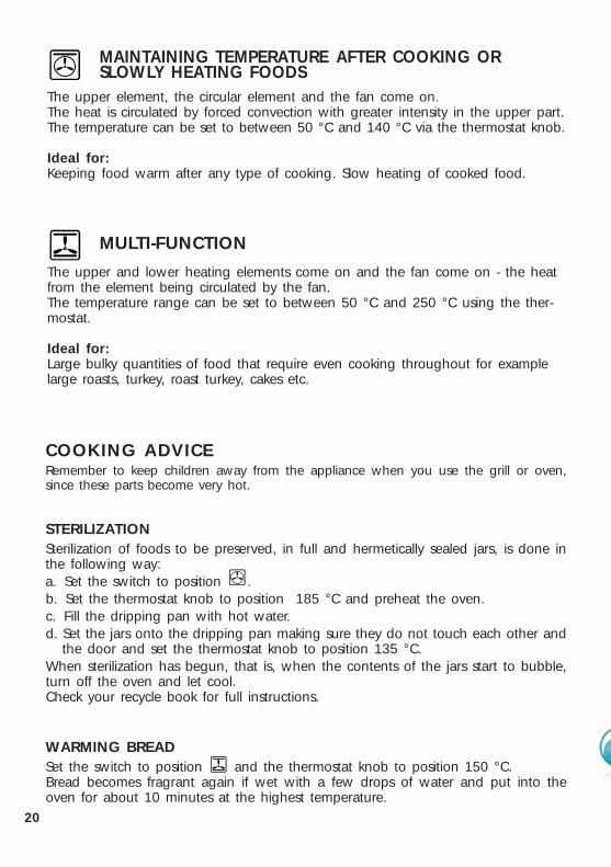
MAINTAINING TEMPERATURE AFTER COOKING OR SLOWLY HEATING FOODS
The upper element, the circular element and the fan come on. The heat is circulated by forced convection with greater intensity in the upper part. The temperature can be set to between 50 °C and 140 °C via the thermostat knob.
Ideal for:Keeping food warm after any type of cooking. Slow heating of cooked food.
MULTI-FUNCTION
The upper and lower heating elements come on and the fan come on - the heatfrom the element being circulated by the fan. The temperature range can be set to between 50 °C and 250 °C using the ther-mostat.
Ideal for:Large bulky quantities of food that require even cooking throughout for examplelarge roasts, turkey, roast turkey, cakes etc.
COOKING ADVICERemember to keep children away from the appliance when you use the grill or oven,since these parts become very hot.
STERILIZATIONSterilization of foods to be preserved, in full and hermetically sealed jars, is done inthe following way:a. Set the switch to position . b. Set the thermostat knob to position 185 °C and preheat the oven. c. Fill the dripping pan with hot water. d. Set the jars onto the dripping pan making sure they do not touch each other and
the door and set the thermostat knob to position 135 °C.When sterilization has begun, that is, when the contents of the jars start to bubble,turn off the oven and let cool.Check your recycle book for full instructions.
WARMING BREADSet the switch to position and the thermostat knob to position 150 °C. Bread becomes fragrant again if wet with a few drops of water and put into theoven for about 10 minutes at the highest temperature.

21
USE OF THE GRILLPreheat the oven for about 5 minutes with the door closed. Introduce the food to be cooked, positioning the rack as close to the grill as possi-ble.The dripping pan should be placed under the rack to catch the cooking juicesand fats.
ROASTINGTo obtain classical roasting, it is necessary to remember:
■ that it is advisable to maintain a temperature between 180 °C and 200 °C. ■ that the cooking time depends on the quantity and the type of foods.
GRILLING AND COOKING AU GRATIN As the hot air completely covers the food to be cooked, grilling may be done with the food on the rack in the oven. The knob should be switched to position .The thermostat should be set to 50 °C and 200 °C max and the oven pre-heated.The food should be placed on a rack in the oven for the required cooking time.Adding a few dabs of butter before the end of the cooking time gives the golden“au gratin” effect.
SIMULTANEOUS COOKING OF DIFFERENT FOODS
The oven set on position can cook several different foods together. Foods asdiverse as fish and cakes can be cooked together without the cross transference offlavours. This is because the fats and cooking smell that would normally bedeposited on the different foods are oxidised and are not absorbed by the foods.The cooking temperature of the foods, however must be within 20 °C-25 °C ofeach other. The food with the longest cooking time will be put into the oven firstand the other foods are added as necessary according to their cooking times.
WARNING: Accessible parts may become hot when the grill is used.Children should be kept away.

22
AUTO
Figure 22
Electronic programmer (some models only)
The electronic programmer is a device which groups together the following func-tions:
■ 24 hours clock with illuminated display■ Timer (up to 23 hours and 59 minutes) ■ Program for automatic oven cooking■ Program for semi-automatic oven cooking
Description of the buttons:
Timer
Cooking time
End of cooking time
Manual position and cancellation of the inserted cooking programme
Advancement of the numbers of all programs
Turning back of the numbers of all programs and changing the frequencyof the audible signal.
Description of the illuminated symbols:
AUTO -flashing - Programmer in automatic position but not programmedAUTO - always illuminated - Programmer in automatic position with program inserted.
Automatic cooking taking place
Timer in operation
and AUTO - flashing - Program error.(The time of day lies between the calculated cooking start and end time).
Note: Select a function by the respective button and, in 5 seconds, set the requiredtime with the / buttons (“one-hand” operation).A power cut zeroes the clock and cancels the set programmes.

23
Figure 23
Figure 24
ELECTRONIC CLOCK (fig. 23)The illuminated figures on the clock represent hours and minutes on 24 hour clock.When first connected, or after a power failure, three zeros will flash on the display.To set the time press the button and then the or Please note that changing the hour button deletes any cooking program.
NORMAL COOKING WITHOUT THE USE OF THE PROGRAMMERTo manually use the oven without the aid of the programmer, it is necessary to cancelthe flashing AUTO by pushing the button (AUTO will be switched off and thesymbol will come on - Fig. 24). Attention: If the AUTO symbol is on, a cooking program has already been programmed.By pressing the you can cancel the set program & switch to manual mode.If the oven is switched on, you must manually switch it off.

24
Figure 25
ELECTRONIC TIMERThe timer program consists only of a buzzer which may be set for a maximum periodof 23 hours and 59 minutes. If AUTO is flashing on the panel, push the button.To set the time, push the button and the or until you obtainthe desired time on the panel (fig. 24). Having finished the setting, the clock hour will appear on the panel and the willbe illuminated. The countdown will start immediately and the time remaining is shown by pressingthe . At the end of the elapsed time, the will go out and an intermittent buzzer willgo off; this can be stopped by pressing any of the buttons.
SETTING THE FREQUENCY OF THE AUDIBLE SIGNALThe selection from 3 possibilities of sound can be made by pressing the button.
25
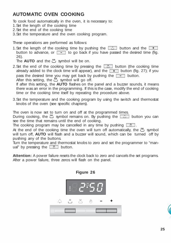
Figure 26
AUTOMATIC OVEN COOKINGTo cook food automatically in the oven, it is necessary to:1.Set the length of the cooking time 2.Set the end of the cooking time 3.Set the temperature and the oven cooking program.
These operations are performed as follows: 1.Set the length of the cooking time by pushing the button and the
button to advance, or to go back if you have passed the desired time (fig.26).The AUTO and the symbol will be on.
2.Set the end of the cooking time by pressing the button (the cooking timealready added to the clock time will appear), and the button (fig. 27); if youpass the desired time you may get back by pushing the button. After this setting, the symbol will go off. If after this setting, the AUTO flashes on the panel and a buzzer sounds, it meansthere was an error in the programming. If this is the case, modify the end of cookingtime or the cooking time itself by repeating the procedure above.
3.Set the temperature and the cooking program by using the switch and thermostatknobs of the oven (see specific chapters).
The oven is now set to turn on and off at the programmed times.During cooking, the symbol remains on. By pushing the button you cansee the time that remains until the end of cooking.The cooking program may be cancelled in any time by pushing . At the end of the cooking time the oven will turn off automatically, the symbolwill turn off, AUTO will flash and a buzzer will sound, which can be turned off bypushing any of the buttons. Turn the temperature and thermostat knobs to zero and set the programmer to “man-ual” by pressing the button.
Attention: A power failure resets the clock back to zero and cancels the set programs. After a power failure, three zeros will flash on the panel.

26
Figure 27
SEMI - AUTOMATIC COOKINGThis function is only used to set the END of the cooking time of the oven. There aretwo ways of setting this function.
1. Set the length of the cooking time by pushing the button and the button to advance, or to go backwards (Fig. 26). This sets the desired “stop”time.or
2.Set the end of the cooking time by pushing the button and the buttonto advance, or to go backwards if you have passed the desired time (Fig.26). AUTO and the symbol will be on.Then set the temperature and the cooking program using the oven switch andthermostat knob (see relevant sections for details). The oven is now set to turn on and off at the programmed times. During cooking, the symbol remains on and by pressing the button youcan see the time that remains till the end of the cooking. The cooking time can be cancelled at any time by pushing the button.
At the end of the cooking, the symbol will turn off, the AUTO will flash and abuzzer will sound. The buzzer can be cancelled by pressing any of the buttons.Turn the temperature and thermostat knobs to zero and set the programmer to“manual” by pressing the button.

27
Figure 28
Cut-off timer (some models only)
TIMERThe timer will operate the oven for a preset time.
1) Starting up. After setting the function selector and thermostat to the required mode and tem-perature, rotate the timer knob clockwise until you reach the required cooking time(max 120 minutes). Once this time has elapsed, the timer will return to the “ ” position and the ovenwill automatically switch off.
2) Manual position.If the cooking time is longer than two hours or if you wish to use the oven manually,switching it off as required, the knob must be turned to position .
ATTENTION:To set the 120’ cut-off timer please turn knob in CLOCKWISE DIRECTIONONLY.
When turning oven off you can turn knob anti-clockwise.

28
CLEANING and MAINTENANCE
GENERAL ADVICE ■ Before you begin cleaning, you must ensure that the appliance is
switched off. ■ It is advisable to clean when the appliance is cold and especially when
cleaning the enamelled parts. ■ Avoid leaving alkaline or acidic substances (lemon juice, vinegar, etc.) on the
surfaces. ■ Avoid using cleaning products with a chlorine or acidic base.■ Do not use a steam cleaner because the moisture can get into the
appliance thus make it unsafe.■ Stainless steel surfaces: clean with a suitable product. Always dry thoroughly.
Do not use harsh abrasive cleaners or sharp metal scrapers to clean the oven doorglass since they can scratch the surface, which may result in shattering of theglass.
WARNINGWhen correctly installed, your product meets all safety requirements laiddown for this type of product category. However special care should betaken around the rear or the underneath of the appliance as these areasare not designed or intended to be touched and may contain sharp orrough edges, that may cause injury.
29
PAINTED PARTS AND SILKSCREEN PRINTED SURFACESClean using an appropriate product. Always dry thoroughly.
IMPORTANT: these parts must be cleaned very carefully to avoid scratching and abra-sion. You are advised to use a soft cloth and neutral soap. CAUTION: Do not use abrasive substances or non-neutral detergents as thesewill irreparably damage the surface.
GLASS CONTROL PANEL (MODELS WITH GLASS CONTROL PANEL)
Clean using an appropriate product.Always dry thoroughly.Do not use harsh abrasive cleaners or sharp metal scrapers to clean the control panelsince they can scratch the surface, which may result in shattering of the glass.
ENAMELLED PARTS All the enamelled parts must be cleaned with a sponge and soapy water only or othernon-abrasive products. Dry preferably with a microfibre or soft cloth.
STAINLESS STEEL SURFACE (stainless steel models)■ CAUTION:
The stainless steel front surfaces (control panel, oven door) used in this ovenare protected with a Special Lacquer to reduce finger-print marks. To avoiddamaging this lacquer, do not clean the stainless steel with abrasive cleanersor abrasive cloths or scouring pads.
ONLY SOAP/WARM WATER MUST BE USED TO CLEAN THE STAINLESSSTEEL SURFACES.

30
GRILL HEATING ELEMENT■ The heating element is self-cleaning and does not require maintenance.
The grill is secured to the rear wall of the oven on a hinge system that allowsit to be lowered to allow proper access when cleaning the oven ceiling(fig. 14 at page 13).
GREASE FILTER■ Clean the filter after any cooking! The grease filter can be removed for cleaning
and should be washed regularly in hot soapy water (fig. 15 at page 13). ■ Always dry the filter properly before fitting it back into the oven.
ADVICE FOR USE AND MAINTENANCE OF CATALYTIC PANELS(models with electronic programmer only)The catalytic panels are covered with special microporous enamel which absorbsand does away with oil and fat splashes during normal baking over 200 °C. If,after cooking very fatty foods, the panels remain dirty, operate the oven “idling” onmax temperature for about 30 minutes. These panels do not require to becleaned, however it is advised to periodically remove them from the oven (at leastthe side panels) and to wash them with tepid soapy water and then wipe off witha soft cloth. DO NOT CLEAN OR WASH THEM WITH ABRASIVE PRODUCTS OR WITHPRODUCTS CONTAINING ACIDS OR ALKALIS.
The side panels are reversible and when the catalytic microporous enameldegrades, they can be turned to the other side.
INSIDE OF OVEN■ The oven should always be cleaned after use when it has cooled down.
The cavity should be cleaned using a mild detergent solution and warm water.Suitable proprietary chemical cleaners may be used after first consulting with themanufacturers recommendations and testing a small sample of the oven cavity.Abrasive cleaning agents or scouring pads/cloths should not be used on thecavity surface.
■ NOTE: The manufacturers of this appliance will accept no responsibility for dam-age caused by chemical or abrasive cleaning.
■ Do not store flammable material in the oven.

31
REPLACING THE OVEN LAMPWARNING: Ensure the appliance is switched off before replacing the lampto avoid the possibility of electric shock.
■ Let the oven cavity and the heating elements to cool down;
■ Switch off the electrical supply;
LEFT LAMP (models with electronic programmer only):
■ Remove the left wire rack and the side catalytic panel by unscrewing the fix-ing screws (see chapter USING THE OVEN FOR THE FIRST TIME at page 12).
■ Press down from the top the protective cover A (fig. 29) and remove it by rotat-ing on the lower side. IMPORTANT: never use screwdrivers or other utensils toremove the cover A. This could damage the enamel of the oven or the lam-pholder. Operate only by hands.
■ Unscrew and replace the bulb B with a new one suitable for high temperatures(300°C) having the following specifications: 230-240V 50 Hz, 25W, E14.
■ Refit the protective cover A operating in reverse order. ATTENTION: the notchin the inner edge of the cover must be oriented toward the lamp.
■ Assemble the side catalytic panel and the left wire rack.
TOP RIGHT LAMP (all models):
■ Remove the protective cover C (fig. 29);
■ Unscrew and replace the bulb B with a new one suitable for high temperatures(300 °C) having the following specifications: 230-240V 50 Hz, (15 W for modelswith cut-off timer and 25 W for models with electronic programmer), E14;
■ Refit the protective cover;
NOTE: Oven bulb replacement is not covered by your guarantee.
AB B C
1
2A
A
Figure 29
A
A
AB B C
1
2

32
B
A
C
REMOVING THE OVENDOOR WITH NOTREMOVABLE INNER GLASS(models with cut-off timer only)
The oven door can easily be removedas follows:
– Open the door to the full extent (fig.30a).
– Open the lever A completely on theleft and right hinges (fig. 30b).
– Hold the door as shown in fig. 30.
– Gently close the door until left andright hinge levers A are hooked topart B of the door (fig. 30c).
– Withdraw the hinge hooks from theirlocation following arrow C (fig. 30d).
– Rest the door on a soft surface.
– To replace the door, repeat the abovesteps in reverse order.
Figure 30
Figure 30a
Figure 30b
Figure 30c
Figure 30d
A
B
C
33
B
A
C
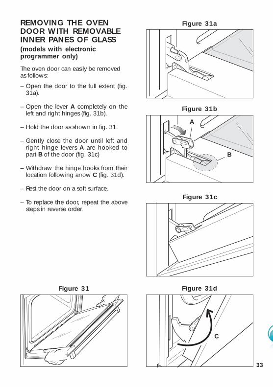
REMOVING THE OVENDOOR WITH REMOVABLEINNER PANES OF GLASS(models with electronicprogrammer only)
The oven door can easily be removedas follows:
– Open the door to the full extent (fig.31a).
– Open the lever A completely on theleft and right hinges (fig. 31b).
– Hold the door as shown in fig. 31.
– Gently close the door until left andright hinge levers A are hooked topart B of the door (fig. 31c)
– Withdraw the hinge hooks from theirlocation following arrow C (fig. 31d).
– Rest the door on a soft surface.
– To replace the door, repeat the abovesteps in reverse order.
Figure 31
Figure 31a
Figure 31b
Figure 31c
Figure 31d
C
A
B

34
CLEANING THE INNERPANES OF GLASS (models with electronicprogrammer only)
The oven door is fitted with no. 3panes: - no. 1 outside;- no. 1 inner;- no. 1 in the middle.To clean all panes on both sides it isnecessary to remove the inner and themiddle panes as follows:
REMOVING THE MIDDLE ANDINNER PANES OF GLASS
1. Lock the door open:• Fully open the oven door (fig. 32).• Fully open the lever A on the left
and right hinges. (fig. 33).• Gently close the door (fig. 34) until
the left and right hinges arehooked to part B of the door (fig.33).
2. Remove the inner pane:• Remove the seal G by unhooking
the no. 3 fixing hooks (fig. 35).• Gently pull out the inner pane of
glass (fig. 36).• Clean the glass with an appropriate
cleaner. Dry thoroughly, and placeon a soft surface.
B
A
Figure 34
Figure 33
Figure 32
Figure 35
Figure 36
A
B
G

35
1
2
3. Remove the middle pane:•Gently unlock the middle pane of
glass from the bottom clamps bymoving it as in fig. 38.
•Gently lift the bottom edge of thepane (arrow 1 in fig. 39) andremove it by pulling it out from thetop clamps (arrow 2 in fig. 39).
•Clean the glass with an appropriatecleaner. Dry thoroughly, and placeon a soft surface.
Now you can also clean the inside ofthe outer glass.
Figure 37
Figure 38
Figure 39

36
REPLACING THE MIDDLEAND INNER PANES OFGLASS1. Make sure the door is locked open
(see fig. 34).2. Replace the middle pane:
• Check that the four rubber padsare in place (M in fig. 40).
• Check that you are holding thepane the correct way. You shouldbe able to read the wording on itas it faces you.
• Gently insert the top edge of thepane into the top clamps (arrow 1in fig. 41), then lower the paneand insert the bottom edge intothe bottom clamps (arrow 2 in fig.41); and then slide the pane intoposition (fig. 42).
M
1 2
1
Figure 40
Figure 41
Figure 42
M

37
D
Figure 47
Figure 43
E
F
Figure 46
H
Figure 45
Figure 44
A
Figure 49
Figure 48
It is normal the opened gap between thetop edge of the inner glass and the sealedgasket. This allows the cooling aircirculation.
D
EF
H
GA
3. Replace the inner pane:• Check that the four rubber pads
are in place (D in fig. 43).• Check that you are holding the
pane the correct way. You shouldbe able to read the wording on itas it faces you.
• Insert the pane in the left E andright F slide guides (fig. 44), andgently slide it to the retainers H(Fig. 45).
• Reassemble the seal G in thecorrect way (fig. 46) by hookingthe no. 3 fixing hooks in the properholes (fig. 47).
4. Unlock the oven door by opening itcompletely and closing the lever Aon the left and right hinges (fig. 49).

38
TROUBLESHOOTING:If you experience a problem with your oven, check the following points before callingour Customer Service Centre for assistance.
1. The power is switched on.2. The controls are switched on.3. The 120’ cut-off or the electronic programmer are set to manual.4. Both the fuse and the mains fuse are intact.
Should you still require assistance please contact our Customer Service Centre foryour nearest Authorised Delonghi Service Agent.

39
Descriptions and illustrations in this booklet are given as simply indicative. The manufacturer reserves the right,considering the characteristics of the models described here, at any time and without notice, to make eventualnecessary modifications for their construction or for commercial needs.

Cod. 1103184 ß4