Embed Size (px)
Citation preview
Remote control light color, light mode and fan speed Remote start or turn off PCAutomatically detect temperature changes to adjust Six port Addressable RGB LED device connectorsFour port for 4pin or 3pin fan connectorsLED color and fan speed
Multifunction Addressable RGB control box with remote
LSB02
Product Overview
Specification
DIY Parts
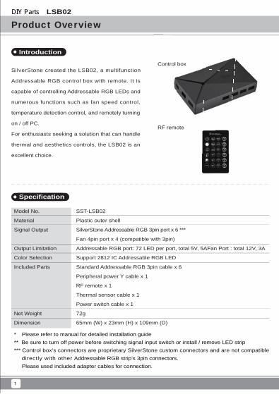
SilverStone created the LSB02, a multifunction
Addressable RGB control box with remote. It is
capable of controlling Addressable RGB LEDs and
numerous functions such as fan speed control,
temperature detection control, and remotely turning
on / off PC.
For enthusiasts seeking a solution that can handle
thermal and aesthetics controls, the LSB02 is an
excellent choice.
Model No.
Material
Signal Output
Output Limitation
Color Selection
Included Parts
Net Weight
Dimension
SST-LSB02
Plastic outer shell
SilverStone Addressable RGB 3pin port x 6 ***
Fan 4pin port x 4 (compatible with 3pin)
Addressable RGB port: 72 LED per port, total 5V, 5AFan Port : total 12V, 3A
Support 2812 IC Addressable RGB LED
Standard Addressable RGB 3pin cable x 6
Peripheral power Y cable x 1
RF remote x 1
Thermal sensor cable x 1
Power switch cable x 1
72g
65mm (W) x 23mm (H) x 109mm (D)
LSB02
Introduction
1
RF remote
Control box
* Please refer to manual for detailed installation guide** Be sure to turn off power before switching signal input switch or install / remove LED strip*** Control box’s connectors are proprietary SilverStone custom connectors and are not compatible directly with other Addressable RGB strip’s 3pin connectors. Please used included adapter cables for connection.
DIY Parts LSB02
2
Installation guide
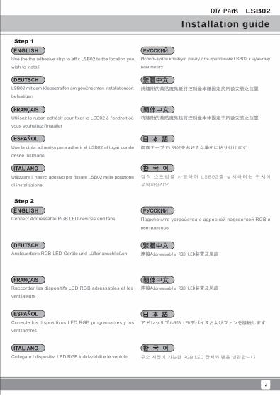
Step 2
連接Addressable RGB LED裝置及風扇
アドレッサブルRGB LEDデバイスおよびファンを接続します
Подключите устройства с адресной подсветкой RGB и
вентиляторы
连接Addressable RGB LED装置及风扇
주소 지정이 가능한 RGB LED 장치와 팬을 연결합니다
Ansteuerbare RGB-LED-Geräte und Lüfter anschließen
Collegare i dispositivi LED RGB indirizzabili e le ventole
Connect Addressable RGB LED devices and fans
Raccorder les dispositifs LED RGB adressables et les
ventilateurs
Conecte los dispositivos LED RGB programables y los
ventiladores
Step 1
將隨附的背貼魔鬼氈將控制盒本體固定於所欲安裝之位置
両面テープでLSB02をお好きな場所に貼り付けます
Используйте клейкую ленту для крепления LSB02 к нужному
вам месту
将随附的背贴魔鬼毡将控制盒本体固定于所欲安装之位置
접착 스트립을 사용하여 LSB02를 설치하려는 위치에
부착하십시오
LSB02 mit dem Klebestreifen am gewünschten Installationsort
befestigen
Utilizzare il nastro adesivo per fissare LSB02 nella posizione
di installazione
Use the the adhesive strip to affix LSB02 to the location you
wish to install
Utilisez le ruban adhésif pour fixer le LSB02 à l'endroit où
vous souhaitez l'installer
Use la cinta adhesiva para adherir el LSB02 al lugar donde
desee instalarlo
DIY Parts LSB02
3
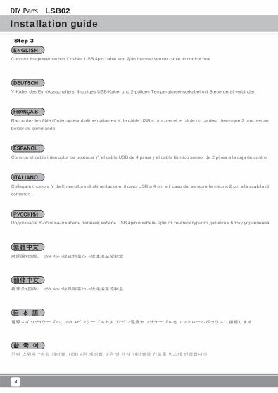
Installation guideStep 3
將開關Y型線、 USB 4pin線及測溫2pin線連接至控制盒
電源スイッチYケーブル、USB 4ピンケーブルおよび2ピン温度センサケーブルをコントロールボックスに接続します
Подключите Y-образный кабель питания, кабель USB 4pin и кабель 2pin от температурного датчика к блоку управления
将开关Y型线、 USB 4pin线及测温2pin线连接至控制盒
전원 스위치 Y자형 케이블, USB 4핀 케이블, 2핀 열 센서 케이블을 컨트롤 박스에 연결합니다
Y-Kabel des Ein-/Ausschalters, 4-poliges USB-Kabel und 2-poliges Temperatursensorkabel mit Steuergerät verbinden
Collegare il cavo a Y dell'interruttore di alimentazione, il cavo USB a 4 pin e il cavo del sensore termico a 2 pin alla scatola di
comando
Connect the power switch Y cable, USB 4pin cable and 2pin thermal sensor cable to control box
Raccordez le câble d'interrupteur d'alimentation en Y, le câble USB 4 broches et le câble du capteur thermique 2 broches au
boîtier de commande
Conecte el cable interruptor de potencia Y, el cable USB de 4 pines y el cable térmico sensor de 2 pines a la caja de control
DIY Parts LSB02
4
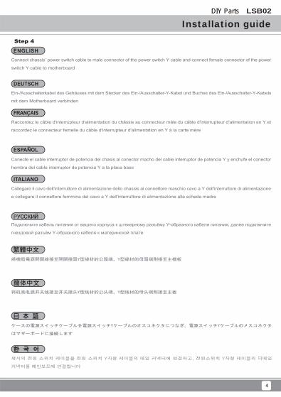
Installation guideStep 4
將機殼電源開關線接至開關接頭Y型線材的公頭端,Y型線材的母頭端則接至主機板
ケースの電源スイッチケーブルを電源スイッチYケーブルのオスコネクタにつなぎ、電源スイッチYケーブルのメスコネクタ
はマザーボードに接続します
Подключите кабель питания от вашего корпуса к штекерному разъёму Y-образного кабеля питания, далее подключите
гнездовой разъём Y-образного кабеля к материнской плате
将机壳电源开关线接至开关接头Y型线材的公头端,Y型线材的母头端则接至主板
섀시의 전원 스위치 케이블을 전원 스위치 Y자형 케이블의 메일 커넥터에 연결하고, 전원스위치 Y자형 케이블의 피메일
커넥터를 메인보드에 연결합니다
Ein-/Ausschalterkabel des Gehäuses mit dem Stecker des Ein-/Ausschalter-Y-Kabel und Buchse des Ein-/Ausschalter-Y-Kabels
mit dem Motherboard verbinden
Collegare il cavo dell'interruttore di alimentazione dello chassis al connettore maschio cavo a Y dell'interruttore di alimentazione
e collegare il connettore femmina del cavo a Y dell'interruttore di alimentazione alla scheda madre
Connect chassis’ power switch cable to male connector of the power switch Y cable and connect female connector of the power
switch Y cable to motherboard
Raccordez le câble d'interrupteur d'alimentation du châssis au connecteur mâle du câble d'interrupteur d'alimentation en Y et
raccordez le connecteur femelle du câble d'interrupteur d'alimentation en Y à la carte mère
Conecte el cable interruptor de potencia del chasis al conector macho del cable interruptor de potencia Y y enchufe el conector
hembra del cable interruptor de potencia Y a la placa base
DIY Parts LSB02
5
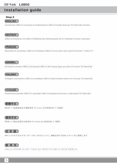
Installation guideStep 5
Raccordez le connecteur USB 2.0 à l'embase USB 2.0 d'une carte mère ayant la fonction " Veille 5 V"
USB-2.0-Anschluss mit USB-2.0-Stiftleiste des Motherboards mit 5-V-Standby-Funktion verbinden
Connect the USB 2.0 connector to motherboard’s USB 2.0 header that has “5V Stand By” function
将USB 2.0接头连接至主板具有 5V Stand By功能的USB 2.0插座
將USB 2.0接頭連接至主機板具有 5V Stand By功能的USB 2.0A插座
Подключите разъём USB 2.0 к разъёму USB 2.0 материнской платы с функцией “5V Stand By”
USB 2.0コネクタをマザーボードの「5Vスタンバイ」機能を有するUSB 2.0ヘッダに接続します
USB 2.0 커넥터를 “5V 대기” 기능이 있는 메인보드의 USB 2.0 헤더에 연결합니다
Collegare il connettore USB 2.0 al collettore USB 2.0 della scheda madre con funzione “5V Stand By”
Enchufe el conector USB 2.0 al cabezal USB 2.0 de la placa base que tiene la función “5V Stand By”
DIY Parts LSB02
6
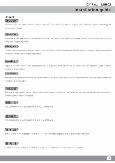
Installation guideStep 6
將感溫線材前端黏貼至具有明顯熱度變化之硬體表面
温度センサケーブルの前側を、ご使用のハードウェアで最も高温が予想される部分に貼り付けます
Закрепите переднюю часть кабеля температурного датчика на поверхность вашего оборудования, имеющего
наибольший возможный нагрев
将感温线材前端黏贴至具有明显热度变化之硬件表面
열 센서 케이블의 전면을 온도 변화가 가장 클 것으로 예상되는 하드웨어 표면에 고정합니다
Vorderseite des Temperatursensorkabels an die Oberfläche der gewünschten Hardware mit der potenziell größten
Temperaturänderung kleben
Attaccare il lato anteriore del cavo del sensore termico sulla superficie dell'hardware desiderato con potenziale per la massima
variazione di temperatura
Stick the front side of the thermal sensor cable on the surface of hardware of your choice that has potential for biggest
temperature change
Collez la partie avant du câble du capteur thermique sur la surface du matériel de votre choix, présentant potentiellement la
variation de température la plus importante
Pegue el lado frontal del cable sensor térmico a la superficie del hardware de su elección que en potencia tenga el mayor
cambio de temperatura
DIY Parts LSB02
7
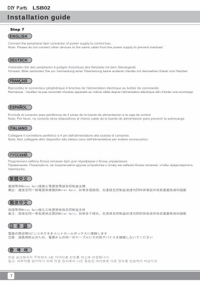
Installation guideStep 7
連接帶有Molex 4pin接頭之電源供電線至控制盒主體 備註: 連接至同一條電源供應器的Molex 4pin,如有多個接頭,在連接至控制盒後請勿同時供電給其他裝置避免線材超載
電源の周辺用4ピンコネクタをコントロールボックスに接続します
注意: 過負荷防止のため、電源からの同一のケーブルにその他デバイスを接続しないでください
Подключите кабель блока питания 4pin для периферии к блоку управления.Примечание: Пожалуйста, не подключайте другие устройства к этому же кабелю блока питания, чтобы предотвратить перегрузку
连接带有Molex 4pin接头之电源供电线至控制盒主体 备注: 连接至同一条电源供应器的Molex 4pin,如有多个接头,在连接至控制盒后请勿同时供电给其他装置避免线材超载
전원 공급장치의 주변장치 4핀 커넥터를 컨트롤 박스에 연결합니다.참고: 과부하를 방지하기 위해 전원 장치에서 나온 동일한 케이블에 다른 장치를 연결하지 마십시오
Verbinden Sie den peripheren 4-poligen Anschluss des Netzteils mit dem Steuergerät.Hinweis: Bitte verbinden Sie zur Vermeidung einer Überlastung keine anderen Geräte mit demselben Kabel vom Netzteil
Collegare il connettore periferico a 4 pin dell'alimentatore alla scatola di comando.Nota: Non collegare altro dispositivi allo stesso cavo dall'alimentatore per evitare sovraccarico
Connect the peripheral 4pin connector of power supply to control box.Note: Please do not connect other devices to the same cable from the power supply to prevent overload
Raccordez le connecteur périphérique 4 broches de l'alimentation électrique au boîtier de commande.Remarque : Veuillez ne pas raccorder d'autres appareils au même câble depuis l'alimentation électrique afin d’éviter une surcharge
Enchufe el conector para periféricos de 4 pines de la fuente de alimentación a la caja de control.Nota: Por favor, no conecte otros dispositivos al mismo cable de la fuente de alimentación para prevenir la sobrecarga
DIY Parts LSB02
8
Installation guideStep 8
Use remote to control colors and fans speed / Remote guide
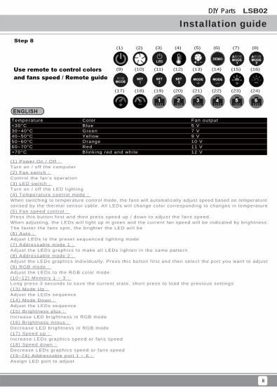
Temperature<30°C30~40°C40~50°C50~60°C60~70°C>70°C
ColorBlueGreenYel lowOrangeRedBl inking red and white
Fan output5 V7 V9 V10 V11 V12 V
(1) Power On / Off : Turn on / of f the computer (2) Fan switch : Control the fan's operat ion (3) LED switch : Turn on / of f the LED l ight ing(4) Temperature control mode : When switching to temperature control mode, the fans will automatically adjust speed based on temperature sensed by the thermal sensor cable. All LEDs wil l change color corresponding to changes in temperature(5) Fan speed control : Press th is button f i rst and then press speed up / down to adjust the fans speed. When adjusting, the LEDs wil l l ight up in green and the current fan speed wil l be indicated by brightness. The faster the fans spin, the br ighter the LED wi l l be(6) Auto : Adjust LEDs to the preset sequenced l ight ing mode(7) Addressable mode 1 : Adjust the LEDs graphics to make al l LEDs l ighten in the same pattern (8) Addressable mode 2 : Adjust the LEDs graphics individual ly. Press this button f i rst and then select the port you want to adjust(9) RGB mode : Adjust the LEDs to the RGB color mode (10~12) Memory 1 ~ 3 : Long press 3 seconds to save the current state, short press to load the previous sett ings(13) Mode Up : Adjust the LEDs sequence(14) Mode Down : Adjust the LEDs sequence(15) Br ightness plus : Increase LED br ightness in RGB mode(16) Br ightness minus : Decrease LED br ightness in RGB mode(17) Speed up : Increase LEDs graphics speed or fans speed(18) Speed down : Decrease LEDs graphics speed or fans speed(19~24) Addressable port 1 ~ 6 : Assign LED port to adjust
(1) (2) (3) (4) (5) (6) (7) (8)
(9) (10) (11) (12) (13) (14) (15) (16)
(17) (18) (19) (20) (21) (22) (23) (24)
DIY Parts LSB02
9
Installation guide
Temperatur< 30 °C30 – 40 °C40 – 50 °C50 – 60 °C60 – 70 °C> 70 °C
FarbeBlauGrünGelbOrangeRotBl inkt rot und weiß
Lüfterausgang5 V7 V9 V10 V11 V12 V
(1) Ein-/Ausschal ten :
Computer ein-/ausschal ten
(2) Lüfterschal ter :
Lüf terbedienung steuern
(3) LED-Schal ter :
LED-Beleuchtung ein-/ausschal ten
(4) Temperatursteuerungsmodus :
Beim Umschalten in den Temperatursteuerungsmodus passen die Lüfter die Geschwindigkeit automatisch
basierend auf der vom Temperatursensorkabel erkannten Temperatur an. Al le LEDs ändern ihre Farbe
entsprechend der Temperaturänderung
(5) Lüftergeschwindigkei tssteuerung :
Drücken Sie erst diese Taste und dann zum Anpassen der Lüftergeschwindigkeit die Schneller- / Langsamer
-Taste. Bei der Anpassung leuchten d ie LEDs grün und d ie aktuel le Lüf tergeschwindigkei t wi rd durch
die Hel l igkei t angezeigt . Je schnel ler s ich die Lüfter drehen, desto hel ler leuchtet d ie LED
(6) Auto :
LEDs auf voreingestel l ter L ichtmodus-Abfolge anpassen
(7) Ansteuerungsmodus 1 :
LED so anpassen, dass al le LEDs in demselben Muster leuchten
(8) Ansteuerungsmodus 2 :
LEDs einzeln anpassen. Drücken Sie erst diese Taste, wählen Sie dann den Port, den Sie anpassen möchten
(9) RGB-Modus :
LEDs auf RGB-Farbmodus anpassen
(10~12) Speicher 1 – 3 :
Zum Speichern des aktuellen Zustands 3 Sekunden lang drücken, zum Laden der vorherigen Einstellungen
kurz drücken
(13) Modus aufwärts :
LED-Abfolge anpassen
(14) Modus abwärts :
LED-Abfolge anpassen
(15) Hel ler :
LED-Hel l igkei t im RGB-Modus erhöhen
(16) Dunkler :
LED-Hel l igkei t im RGB-Modus verr ingern
(17) Schnel ler :
LED- oder Lüftergeschwindigkei t erhöhen
(18) Langsamer :
LED- oder Lüftergeschwindigkei t verr ingern
(19~24) Ansteuerungsport 1 – 6 :
LED-Port zur Anpassung zuweisen
DIY Parts LSB02
10
Installation guide
Température< 30 °C30~40 °C40~50 °C50~60 °C60~70 °C> 70 °C
Color isBleuVertJauneOrangeRougeRouge et b lanc c l ignotant
Sort ie vent i lateur5 V7 V9 V10 V11 V12 V
(1) Mise sous tension / hors tension :Al lume / éteint l 'ordinateur(2) Interrupteur vent i lateur : Contrôle le fonct ionnement du vent i lateur(3) Interrupteur LED : Al lume / éteint l 'éclai rage LED(4) Mode de contrôle de la température : En passant en mode de contrôle de la température, les ventilateurs ajustent automatiquement leur vitesse en fonct ion de la température détectée par le câb le du capteur thermique. Toutes les LED changent de couleur en fonct ion des var iat ions de température(5) Contrôle de la v i tesse du vent i lateur : Appuyez d 'abord sur ce bouton puis appuyez sur Vi tesse + / - pour régler la v i tesse des vent i la teurs. Lors du rég lage, les LED s 'a l lument en ver t e t la v i tesse ac tue l le du vent i la teur es t ind iquée par la luminosi té. Plus les vent i lateurs tournent v i te, p lus les LED sont lumineuses(6) Auto : Règle les LED sur le mode d'éclairage séquencé prédéf in i(7) Mode adressable 1 : Ajuste les graphismes des LED pour que toutes les LED s'éclairc issent dans le même mot i f (8) Mode adressable 2 : Ajuste les graphismes des LED indiv iduel lement. Appuyez d 'abord sur ce bouton puis sélect ionnez le port que vous souhai tez ajuster(9) Mode RGB : Ajuste les LED au mode de couleur RGB(10~12) Mémoire 1 ~ 3 : Appuyez longuement pendan t 3 secondes pour en reg is t re r l ' é ta t ac tue l , appuyez b r ièvement pour charger les réglages précédents(13) Mode + : Ajuste la séquence des LED(14) Mode - : Ajuste la séquence des LED(15) Luminosi té + : Augmente la luminosi té des LED en mode RGB(16) Luminosi té - : Diminue la luminosi té des LED en mode RGB(17) Vi tesse + : Augmente la v i tesse des graphismes des LED ou la v i tesse des vent i lateurs(18) Vi tesse - : Diminue la v i tesse des graphismes des LED ou la v i tesse des vent i lateurs(19~24) Port adressable 1 ~ 6 : Assigne le port LED à ajuster
DIY Parts LSB02
11
Installation guide
Temperatura<30 °C30~40 °C40~50 °C50~60 °C60~70 °C>70 °C
ColorAzulVerdeAmari l loNaranjaRojoRojo y blanco parpadeante
Sal ida del vent i lador5V7V9V10V11V12V
(1) Potencia Encendido/Apagado : Enciende/Apaga el ordenador(2) Interruptor del vent i lador : Controla el funcionamiento del vent i lador(3) Interruptor LED : Enciende/Apaga la i luminación LED(4) Modo de control de temperatura : Cuando se cambia a modo de control de temperatura, los ventiladores ajustarán la velocidad automáticamente según la temperatura detectada por el cable sensor térmico. Todos los LEDs cambiarán de color según los cambios de temperatura(5) Control de la velocidad del vent i lador : Presione este botón pr imero y luego presione velocidad aumentar/reducir para ajustar la velocidad de los ventiladores. Cuando se esté ajustando, los LEDs se i luminarán en verde y la velocidad del venti lador actual será indicada por el br i l lo. Conforme el vent i lador gire más rápido, el LED será más br i l lante(6) Auto : Ajuste los LEDs al modo de i luminación secuenciado preseleccionado(7) Modo programable 1 : Ajuste los gráf icos LEDs para que todos los LEDs se i luminen con el mismo diseño(8) Modo programable 2 : Ajuste los gráf icos LEDs de forma individual. Presione este botón pr imero y luego seleccione el puerto que desee ajustar(9) Modo RGB : Ajuste los LEDs al modo de color RGB(10~12) Memoria 1 ~ 3 : Haga una pulsación larga de 3 segundos para guardar el estado actual, una pulsación corta para cargar la conf iguración previa(13) Aumentar Modo : Ajusta la secuencia LED(14) Reducir Modo : Ajusta la secuencia LED(15) Br i l lo más : Aumenta el br i l lo LED en modo RGB(16) Br i l lo menos : Reduce el br i l lo LED en modo RGB(17) Aumentar Velocidad : Aumenta la velocidad de los gráf icos LEDs o de los vent i ladores(18) Reducir Velocidad : Reduce la velocidad de los gráf icos LEDs o de los vent i ladores(19~24) Puerto 1 ~ 6 programable : Asigne el puerto LED a ajustar
DIY Parts LSB02
12
Installation guide
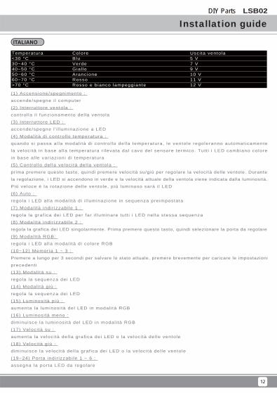
Temperatura<30 °C30~40 °C40~50 °C50~60 °C60~70 °C>70 °C
ColoreBluVerdeGial loArancioneRossoRosso e bianco lampeggiante
Usci ta ventola5 V7 V9 V10 V11 V12 V
(1) Accensione/spegnimento :
accende/spegne i l computer
(2) Interrut tore ventola :
control la i l funzionamento del la ventola
(3) Interrut tore LED :
accende/spegne l ' i l luminazione a LED
(4) Modal i tà di control lo temperatura :
quando s i passa al la modal i tà d i contro l lo del la temperatura, le ventole regoleranno automat icamente
la veloci tà in base al la temperatura r i levata dal cavo del sensore termico. Tutt i i LED cambiano colore
in base al le var iazioni d i temperatura
(5) Control lo del la veloci tà del la ventola :
prima premere questo tasto, quindi premere velocità su/giù per regolare la velocità delle ventole. Durante
la regolazione, i LED si accendono in verde e la velocità attuale della ventola viene indicata dalla luminosità.
Più veloce è la rotazione del le ventole, p iù luminoso sarà i l LED
(6) Auto :
regola i LED al la modal i tà di i l luminazione in sequenza preimpostata
(7) Modal i tà indir izzabi le 1 :
regola la graf ica dei LED per far i l luminare tut t i i LED nel la stessa sequenza
(8) Modal i tà indir izzabi le 2 :
regola la grafica dei LED singolarmente. Prima premere questo tasto, quindi selezionare la porta da regolare
(9) Modal i tà RGB:
regola i LED al la modal i tà di colore RGB
(10~12) Memoria 1 ~ 3 :
Premere a lungo per 3 secondi per salvare lo stato attuale, premere brevemente per caricare le impostazioni
precedent i
(13) Modal i tà su :
regola la sequenza dei LED
(14) Modal i tà giù :
regola la sequenza dei LED
(15) Luminosi tà più :
aumenta la luminosi tà del LED in modal i tà RGB
(16) Luminosi tà meno :
diminuisce la luminosi tà del LED in modal i tà RGB
(17) Veloci tà su :
aumenta la veloci tà del la graf ica dei LED o la veloci tà del le ventole
(18) Veloci tà giù :
d iminuisce la veloci tà del la graf ica dei LED o la veloci tà del le ventole
(19~24) Porta indir izzabi le 1 ~ 6 :
assegna la porta LED da regolare
DIY Parts LSB02
13
Installation guide
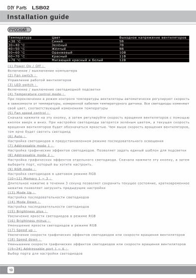
Температура<30 °C30~40 °C40~50 °C50~60 °C60~70 °C>70 °C
ЦветСинийЗелёныйЖёлтыйОранжевыйКрасныйМигающий красный и белый
Выходное напряжение вентиляторов5В7В9В10В11В12В
(1) Power On / Off :
Включение / выключение компьютера
(2) Fan switch :
Управление работой вентиляторов
(3) LED switch :
Включение / выключение светодиодной подсветки
(4) Temperature control mode :
При переключении в режим контроля температуры вентиляторы автоматически регулируют скорость
в зависимости от температуры, измеренной кабелем температурного датчика. Все светодиоды изменяют
свой цвет , соответствующий изменениям температуры
(5) Fan speed control :
Сначала нажмите на эту кнопку , а затем регулируйте скорость вращения вентиляторов с помощью
кнопок вверх и вниз . При настройке светодиоды загорятся зелёным цветом , а текущая скорость
вращения вентиляторов будет обозначаться яркостью . Чем выше скорость вращения вентиляторов ,
тем ярче будет светить светодиод
(6) Auto :
Настройка светодиодов в предустановленном режиме последовательного освещения
(7) Addressable mode 1 :
Настройка графических эффектов светодиодов . Позволяет задать единый шаблон для подсветки
(8) Addressable mode 2 :
Настройка графических эффектов отдельного светодиода . Сначала нажмите эту кнопку , а затем
выберите порт , который вы хотите настроить .
(9) RGB mode :
Настройка светодиодов в цветовом режиме RGB
(10~12) Memory 1 ~ 3 :
Длительное нажатие в течении 3 секунд позволяет сохранить текущее состояние , кратковременное
нажатие позволяет загрузить предыдущие настройки
(13) Mode Up :
Настройка последовательности светодиодов
(14) Mode Down :
Настройка последовательности светодиодов
(15) Br ightness plus :
Увеличение яркости светодиодов в режиме RGB
(16) Br ightness minus :
Уменьшение яркости светодиодов в режиме RGB
(17) Speed up :
Увеличение скорости графических эффектов светодиодов или скорости вращения вентиляторов
(18) Speed down :
Уменьшение скорости графических эффектов светодиодов или скорости вращения вентиляторов
(19~24) Addressable port 1 ~ 6 :
Выбор порта для настройки светодиодов
DIY Parts LSB02
14
Installation guide
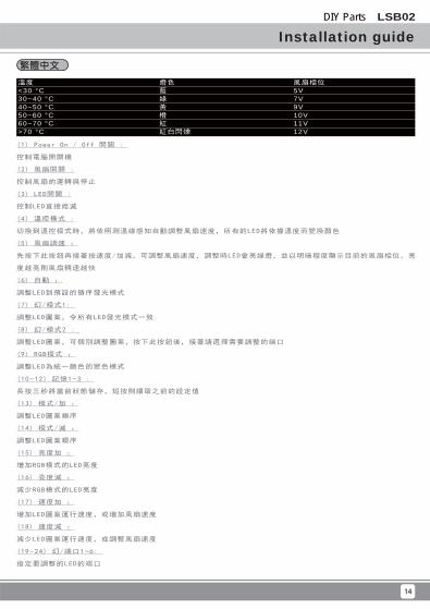
溫度<30 °C30~40 °C40~50 °C50~60 °C60~70 °C>70 °C
燈色藍綠黃橙紅紅白閃爍
風扇檔位5V7V9V10V11V12V
(1) Power On / Off 開關 :
控制電腦開關機
(2) 風扇開關 :
控制風扇的運轉與停止
(3) LED開關 :
控制LED直接熄滅
(4) 溫控模式 :
切換到溫控模式時,將依照測溫線感知自動調整風扇速度,所有的LED將依據溫度而變換顏色
(5) 風扇調速 :
先按下此按鈕再接著按速度/加減,可調整風扇速度,調整時LED會亮綠燈,並以明暗程度顯示目前的風扇檔位,亮
度越亮則風扇轉速越快
(6) 自動 :
調整LED到預設的循序發光模式
(7) 幻/模式1:
調整LED圖案,令所有LED發光模式一致
(8) 幻/模式2 :
調整LED圖案,可個別調整圖案,按下此按鈕後,接著請選擇需要調整的端口
(9) RGB模式 :
調整LED為統一顏色的變色模式
(10~12) 記憶1~3 :
長按三秒將當前狀態儲存,短按則讀取之前的設定值
(13) 模式/加 :
調整LED圖案順序
(14) 模式/減 :
調整LED圖案順序
(15) 亮度加 :
增加RGB模式的LED亮度
(16) 亮度減 :
減少RGB模式的LED亮度
(17) 速度加 :
增加LED圖案運行速度,或增加風扇速度
(18) 速度減 :
減少LED圖案運行速度,或調整風扇速度
(19~24) 幻/端口1~6:
指定要調整的LED的端口
DIY Parts LSB02
15
Installation guide
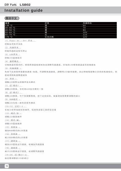
温度<30 °C30~40 °C40~50 °C50~60 °C60~70 °C>70 °C
灯色蓝绿黄橙红红白闪烁
风扇档位5V7V9V10V11V12V
(1) Power On / Off 开关 :
控制台式机开关机
(2) 风扇开关 :
控制风扇的运转与停止
(3) LED开关 :
控制LED直接熄灭
(4) 温控模式 :
切换到温控模式时,将依照测温线感知自动调整风扇速度,所有的LED将依据温度而变换颜色
(5) 风扇调速 :
先按下此按鈕再接著按速度/加減,可調整風扇速度,調整時LED會亮綠燈,並以明暗程度顯示目前的風扇檔位,亮
度越亮則風扇轉速越快
(6) 自动 :
调整LED到默认的循序发光模式
(7) 幻/模式1 :
调整LED图案,令所有LED发光模式一致
(8) 幻/模式2 :
调整LED图案,可个别调整图案,按下此按钮后,接着请选择需要调整的端口
(9) RGB模式 :
调整LED为统一颜色的变色模式
(10~12) 记忆1~3 :
长按三秒将当前状态储存,短按则读取之前的设定值
(13) 模式/加 :
调整LED图案顺序
(14) 模式/减:
调整LED图案顺序
(15) 亮度加 :
增加RGB模式的LED亮度
(16) 亮度减 :
减少RGB模式的LED亮度
(17) 速度加 :
增加LED图案运行速度,或增加风扇速度
(18) 速度减 :
减少LED图案运行速度,或调整风扇速度
(19~24) 幻/端口1~6:
指定要调整的LED的端口
DIY Parts LSB02
16
Installation guide
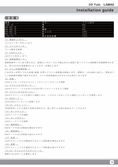
温度< 3 0 ° C3 0 ~ 4 0 ° C4 0 ~ 5 0 ° C5 0 ~ 6 0 ° C6 0 ~ 7 0 ° C> 7 0 ° C
カラー
青
緑
黄色
オレンジ
赤
赤と白の点滅
ファン出力
5 V7 V9 V1 0 V1 1 V1 2 V
(1) 電源オン/オフ :
コンピューターをオン/オフ
(2) ファンスイッチ :
ファン動作を制御
(3) LEDスイッチ :
LEDライトのオン/オフ
(4) 温度制御モード :
温度制御モードに切り替えると、温度センサケーブルで検出された温度に従ってファン回転数が自動調節されま
す。全てのLEDも温度変化によってカラーが変化します
(5) ファン回転数制御 :
このボタンを押してから加速/減速 を押してファン回転数を制御します。調節中、LEDは緑に点灯し、現在のフ
ァン回転数が輝度で表示されます。ファンの回転数が上がるとLEDも明るくなります
(6) 自動:
LEDをプリセットされたライティングシーケンスモードで調節
(7) アドレッサブルモード1 :
LEDのグラフィックスを全てのLEDが同一パターンになるよう調節
(8) アドレッサブルモード2 :
LEDのグラフィックスを個々に調節します。このボタンをおしてから調節したいポートを選択します
(9) RGBモード :
LEDをRGBカラーモードに調節します
(10~12) メモリ 1~3 :
3秒間長押しすると現在の状態が保存され、短く押すと以前の設定がロードされます
(13) モードアップ :
LEDのシーケンスを調節
(14) モードダウン:
LEDのシーケンスを調節
(15) 輝度増加 :
RGBモードでのLED輝度を増加させます
(16) 輝度減少 :
RGBモードでのLED輝度を減少させます
(17) 加速 :
LEDグラフィックスの速度またはファン回転数を増加させます
(18) 減速 :
LEDグラフィックスの速度またはファン回転数を減少させます
(19~24) アドレッサブルポート 1~6:
調節するLEDポートを選択します
DIY Parts LSB02
17
Installation guide
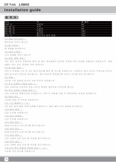
온도<30 °C30~40 °C40~50 °C50~60 °C60~70 °C>70 °C
색파란색녹색노란색주황색빨간색빨간색과 흰색 점멸
팬 출력5V7V9V10V11V12V
(1) 전원 켜기/끄기 :
컴퓨터를 켜거나 끕니다
(2) 팬 스위치 :
팬 작동을 제어합니다
(3) LED 스위치 :
LED 조명를 켜거나 끕니다
(4) 온도 제어 모드 :
온도 제어 모드로 전환하면 팬이 열 센서 케이블에서 감지한 온도에 따라 속도를 자동으로 조정합니다. 모든
LED의 색이 온도 변화에 따라 변합니다
(5) 팬 속도 제어 :
먼저 이 버튼을 누른 후 속도 증가/감소를 눌러 팬 속도를 조정합니다. 조정하는 동안 LED가 녹색으로 켜지고
현재 팬 속도가 밝기로 표시됩니다. 팬이 빠르게 회전할수록 LED가 그만큼 밝게 표시됩니다
(6) 자동:
LED를 사전 설정된 순서의 조명 모드로 조정합니다
(7) 주소 지정이 가능한 모드 1 :
LED 그래픽을 조정하여 모든 LED가 동일한 패턴으로 켜지도록 합니다
(8) 주소 지정이 가능한 모드 2 :
LED 그래픽을 개별적으로 조정합니다. 먼저 이 버튼을 누른 후 조정하려는 포트를 선택합니다
(9) RGB 모드 :
LED를 RGB 색 모드로 조정합니다
(10~12) 메모리 1 ~ 3 :
3초 동안 길게 눌러 현재 상태를 저장하거나, 짧게 눌러 이전 설정을 로드합니다
(13) 모드 위로 :
LED 순서를 조정합니다
(14) 모드 아래로:
LED 순서를 조정합니다
(15) 밝기 증가 :
RGB 모드에서 LED 밝기를 증가시킵니다
(16) 밝기 감소 :
RGB 모드에서 LED 밝기를 감소시킵니다
(17) 속도 증가 :
LED 그래픽 속도 또는 팬 속도를 증가시킵니다
(18) 속도 감소 :
LED 그래픽 속도 또는 팬 속도를 감소시킵니다
(19~24) 주소 지정이 가능한 포트 1 ~ 6 :
조정할 LED 포트를 지정합니다
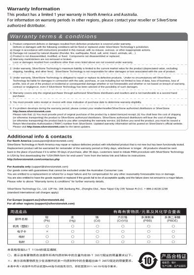
本表格依据SJ/T 11364的规定编制.
○:表示该有害物质在该部件所有均质材料中的含量均在GB/T 26572规定的限量要求以下。
×:表示该有害物质至少在该部件的某一均质材料中的含量超出GB/T 26572规定的限量要求。
本表中有×的部件均符合欧盟RoHS指令的豁免项目,即欧盟第2011/65/EU号指令要求。
产品合格证检验员:检01
生产日期:见产品条码
周邊產品 有毒有害物质/元素及其化学含量表
部件名称
机壳(塑胶)
电子卡
线材
包材
○
×
○
○
○
○
○
○
○
○
○
○
○
○
○
○
○
○
○
○
○
○
○
○
多溴二苯醚(PBDE)
多溴联苯(PBB)
六价铬(Cr(VI))
镉(Cd)
汞(Hg)
铅(Pb)
Warranty InformationThis product has a limited 1 year warranty in North America and Australia. For information on warranty periods in other regions, please contact your reseller or SilverStone authorized distributor.
1. Product component defects or damages resulted from defective production is covered under warranty. Defects or damages with the following conditions will be fixed or replaced under SilverStone Technology’s jurisdiction.a) Usage in accordance with instructions provided in this manual, with no misuse, overuse, or other inappropriate actions.b) Damage not caused by natural disaster (thunder, fire, earthquake, flood, salt, wind, insect, animals, etc…)c) Product is not disassembled, modified, or fixed. Components not disassembled or replaced.d) Warranty mark/stickers are not removed or broken. Loss or damages resulted from conditions other than ones listed above are not covered under warranty.
2. Under warranty, SilverStone Technology’s maximum liability is limited to the current market value for the product (depreciated value, excluding shipping, handling, and other fees). SilverStone Technology is not responsible for other damages or loss associated with the use of product.
3. Under warranty, SilverStone Technology is obligated to repair or replace its defective products. Under no circumstances will SilverStone Technology be liable for damages in connection with the sale, purchase, or use including but not limited to loss of data, loss of business, loss of profits, loss of use of the product or incidental or consequential damage whether or not foreseeable and whether or not based on breach of warranty, contract or negligence, even if SilverStone Technology has been advised of the possibility of such damages.
4. Warranty covers only the original purchaser through authorized SilverStone distributors and resellers and is not transferable to a second hand purchaser.
5. You must provide sales receipt or invoice with clear indication of purchase date to determine warranty eligibility.
6. If a problem develops during the warranty period, please contact your retailer/reseller/SilverStone authorized distributors or SilverStone http://www.silverstonetek.com. Please note that: (i) You must provide proof of original purchase of the product by a dated itemized receipt; (ii) You shall bear the cost of shipping (or otherwise transporting) the product to SilverStone authorized distributors. SilverStone authorized distributors will bear the cost of shipping (or otherwise transporting) the product back to you after completing the warranty service; (iii) Before you send the product, you must be issued a Return Merchandise Authorization (“RMA”) number from SilverStone. Updated warranty information will be posted on SilverStone’s official website. Please visit http://www.silverstonetek.com for the latest updates.
Warranty terms & conditions
Additional info & contactsFor North America ([email protected])SilverStone Technology in North America may repair or replace defective product with refurbished product that is not new but has been functionally tested. Replacement product will be warranted for remainder of the warranty period or thirty days, whichever is longer. All products should be sent back to the place of purchase if it is within 30 days of purchase, after 30 days, customers need to initiate RMA procedure with SilverStone Technology in USA by first downloading the “USA RMA form for end-users” form from the below link and follow its instructions.http://silverstonetek.com/contactus.php
For Australia only ([email protected])Our goods come with guarantees that cannot be excluded under the Australian Consumer Law. You are entitled to a replacement or refund for a major failure and for compensation for any other reasonably foreseeable loss or damage. You are also entitled to have the goods repaired or replaced if the goods fail to be of acceptable quality and the failure does not amount to a major failure. Please refer to above “Warranty terms & conditions” for further warranty details.
SilverStone Technology Co., Ltd. 12F No. 168 Jiankang Rd., Zhonghe Dist., New Taipei City 235 Taiwan R.O.C. + 886-2-8228-1238 (standard international call charges apply)
For Europe ([email protected])For all other regions ([email protected])

G11233790