Embed Size (px)
Citation preview
Struct Multidisc Optim (2010) 41:621–635DOI 10.1007/s00158-009-0435-8
INDUSTRIAL APPLICATION
Multidisciplinary optimization of injection molding systems
Irene Ferreira · Olivier de Weck ·Pedro Saraiva · José Cabral
Received: 11 September 2008 / Revised: 4 August 2009 / Accepted: 25 August 2009 / Published online: 6 October 2009c© Springer-Verlag 2009
Abstract The design of injection molding systems for plas-tic parts relies heavily on experience and intuition. Recently,mold makers have been compelled to shorten lead times,reduce costs and improve process performance due to globalcompetition. This paper presents a framework, based on aMultidisciplinary Design Optimization (MDO) methodol-ogy, which tackles the design of an injection mold by inte-grating the structural, feeding, ejection and heat-exchangesub-systems to achieve significant improvements. To vali-date it single objective optimization is presented leadingto a 42% reduction in cycle time. We also perform multi-ple objective optimization simultaneously minimizing cycletime, wasted material and pressure drop. Sensitivity analysisshows a large impact of the sprue diameter (>1.5 normal-ized sensitivity) highlighting the importance of the feedingsubsystem on overall quality. The results show substantialimprovements resulting in reduced rework and time savingsfor the entire mold design process.
Keywords Injection mold design · MDO ·Global design · Cycle time
I. Ferreira (B) · O. de WeckEngineering Systems Division (ESD),Massachusetts Institute of Technology,Cambridge, MA 02139, USAe-mail: [email protected]
P. SaraivaChemical Engineering Department, University of Coimbra,Coimbra, Portugal
J. CabralEngineering Faculty, University of Porto, Porto, Portugal
Nomenclature
dSprue Sprue diameter [m]lRunner Runner length [m]lGate Gate length [m]dGate Gate diameter [m]αSprue Sprue draft angle [◦]lSprue Sprue length [m]Pinj Injection pressure [Pa]dRunner Runner diameter [m]nRamif Number of ramifications of runnersndownstream Number of ramification streamsnGate Number of gates’ points per partdRelease Distance of part’s release [m]α Coefficient of diffusitivity [m2/s]Aproj Projected area of molded part [m2]
1 Introduction
An injection mold is a high precision tool required for theproduction of plastic parts. Its main purpose is to replicatethe desired geometry of the final plastic part by transformingmolten plastic into its final shape and dimensional details.Currently, the design of an injection mold is a highly inter-active and manual process involving substantial knowledgeof multiple areas, such as mold design features, mold mak-ing processes, molding equipment and part design, all ofwhich are highly coupled to each other. The main chal-lenge is to design and produce a mold that is straightforwardto manufacture, while providing uniform filling and cool-ing of plastic parts. At the same time the tool has to bestrong enough to withstand millions of cyclic internal loadsfrom injection pressures and external clamp pressures, inorder to assure the target part’s reproducibility (Beaumont
622 I. Ferreira et al.
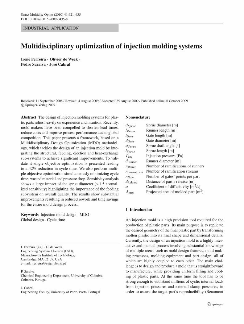
Fig. 1 Typical halves of aninjection mold: cavity (left) andcore (right) (Centimfe 2000)
et al. 2002). In this sense, an injection mold can be seenas a mechanical structure with some functional subsystems,such as the feeding system, heat-transfer system, structuralsystem and ejection system. Usually, this structure is com-posed of two halves, where the top half of the mold iscommonly referred to as the cavity half or the fixed half ofthe mold. The bottom half is known as the core or movablehalf (Fig. 1). In some cases, the cavity and core halves canbe switched.
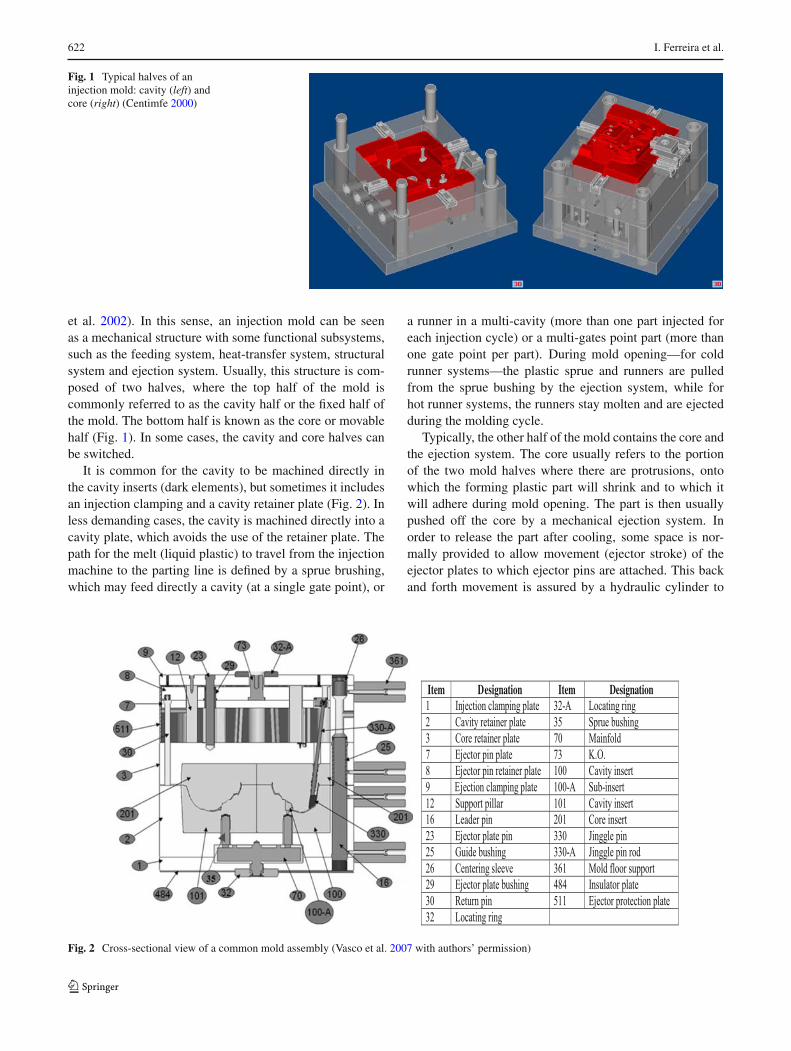
It is common for the cavity to be machined directly inthe cavity inserts (dark elements), but sometimes it includesan injection clamping and a cavity retainer plate (Fig. 2). Inless demanding cases, the cavity is machined directly into acavity plate, which avoids the use of the retainer plate. Thepath for the melt (liquid plastic) to travel from the injectionmachine to the parting line is defined by a sprue brushing,which may feed directly a cavity (at a single gate point), or
a runner in a multi-cavity (more than one part injected foreach injection cycle) or a multi-gates point part (more thanone gate point per part). During mold opening—for coldrunner systems—the plastic sprue and runners are pulledfrom the sprue bushing by the ejection system, while forhot runner systems, the runners stay molten and are ejectedduring the molding cycle.
Typically, the other half of the mold contains the core andthe ejection system. The core usually refers to the portionof the two mold halves where there are protrusions, ontowhich the forming plastic part will shrink and to which itwill adhere during mold opening. The part is then usuallypushed off the core by a mechanical ejection system. Inorder to release the part after cooling, some space is nor-mally provided to allow movement (ejector stroke) of theejector plates to which ejector pins are attached. This backand forth movement is assured by a hydraulic cylinder to
Item Designation Item Designation 1 Injection clamping plate 32-A Locating ring
2 Cavity retainer plate 35 Sprue bushing
3 Core retainer plate 70 Mainfold
7 Ejector pin plate 73 K.O.
8 E
E
jector pin retainer plate 100 Cavity insert
9 jection clamping plate 100-A Sub-insert
12 Support pillar 101 Cavity insert
16 Leader pin 201 Core insert
23 Ejector plate pin 330 Jinggle pin
25 Guide bushing 330-A Jinggle pin rod
26 Centering sleeve 361 Mold floor support
29 Ejector plate bushing 484 Insulator plate
30 Return pin 511 Ejector protection plate
32 Locating ring
Fig. 2 Cross-sectional view of a common mold assembly (Vasco et al. 2007 with authors’ permission)
Multidisciplinary optimization of injection molding systems 623
which the ejector plate is attached. Based on this cycle, themain components of a typical injection mold, and respectivefunctions, are as follows:
(a) Feeding System (including the venting system). Itsmain function is to channel the molten plastic mate-rial coming from the injection nozzle of the moldingmachine and distribute it into each cavity, through therunners and respective gate points. Generally, injec-tion molds can be classified as either “cold runner” or“hot runner” molds. A cold runner refers to a moldin which the feeding system is cooled, solidified andejected with the molded part in each molding cycle. Inthe case of a hot runner mold, the runner is kept in amolten state, avoiding a runner that must be refilledand discarded in each cycle. The hot runner systemis typically composed of two components: the man-ifold and the drop(s). The venting subsystem mustallow for gas release, because when the melt entersinto the cavity the displaced air must have a meansto escape. The design of this subsystem depends onthe part’s geometry, its position in the mold and itsgating;
(b) Heat-transfer System. It supplies the mold with a sys-tem of cooling channels, through which a coolant ispumped. Usually, its main function is to remove heatfrom the mold, so that—once filled—the part is suffi-ciently rigid to be demolded. Note that given the fastcycle time of most machines that the coolant flow iscontinuous and thus some amount of heat evacuationis always ongoing;
(c) Ejection System. Its main function is to knock outthe injection molded parts, in order to release themfrom the mold. Typically, after the mold is opened, thehydraulic cylinder of the injection machine will actu-ate the ejection system to move forward, pushing themolded parts out. It is critical that the ejection systemdoes not cause damage (marks) to completed parts;
(d) Structural System. It must allow the mold (tool) to becoupled into the injection machine and assure the over-all assembly of its components. It is also necessaryto guarantee the alignment and guiding of the mold.According to the type of mold, it involves several metalplates to form a rigid body where some components areassembled together (e.g. locating ring; guide pins andguide bushings, amongst others);
(e) Others: for complex plastic parts, some other mech-anisms, such as slides, lifters, unscrewing devices,amongst others, might also be necessary.
Therefore, the mold design optimization must encom-pass the optimization of four main highly-coupled systems,
Table 1 Subsystems andobjective functions for injectionmold design
System Global objectives
Injection Min cycle time
mold Min cost
Subsystem Local objectives
Feeding Min volume
Min pressure drop
Heat- Max heat transfer
exchange
Ejection Min marks
Structural Min bending
Min deflection
namely the Structural, Feeding, Heat-Exchange and Ejec-tion systems, where each one is characterized by one ormore local objective functions, in order to assure sat-isfaction of both final part and manufacturing processrequirements. Globally, the mold as a system involves theoptimization of two main functions, namely the mold’s costand performance (Table 1). At this stage, the mold’s perfor-mance will be evaluated by its cycle time. The cycle time isdefined as the time required from initial injection of a part,through cooling and ejection to the point where the next partis ready to be injected. It is the major attribute of injectionmolding productivity. Part tolerances and uniformity are setas constraints.
2 Related research
The design of an injection mold is considered criticallyimportant to product quality and efficient processing, aswell as a determining factor for the economics of the entireprocess (Chan et al. 2003; Low 2003). In this sense, andin order to achieve high levels of product quality in lesstime, both academia and industry have been looking for newmethods to address mold design. Therefore, a lot of scien-tific research has been done on mold design and its relatedfields over the last years, mostly on Knowledge-Based (KB)methods (this approach is justified by the extensive empir-ical knowledge about mold component functions). Exam-ples of work in this area are IKB-MOULD (Mok et al.2001), a 3D CAD KB (Chan et al. 2003) and ESMOLD(Chin and Wong 1996). According to Chan et al. (2003),one emergent area of research in the injection molding fieldattempts to generate automatically the design of mold toolcomponents. Although, due to high complexity and sig-nificant mold component interactions, some authors (Chanet al. 2003; Low 2003) consider this approach not to befeasible for the automatic generation of an entire injec-tion mold. Thus, this new approach has been used only tosolve particular aspects of mold design. As examples of this
624 I. Ferreira et al.
research thrust, Mehnen et al. (2004) studied the automa-tion of Heat-Exchange subsystem design while Lam et al.(2004b) pursued a multi-objective approach with integrationof Genetic Algorithms and CAE. On the subject of opti-mal feeding subsystems, Lee and Lin (2006) used FEM,Taguchi’s method and an abductive network to select thebest parameters. Lam et al. (2004a) proposed an automatedgate optimization routine and Shen et al. (2004) developeda modified hill-climbing algorithm in order to determine thebest gate location. These examples highlight the fact thatresearch in injection mold design optimization is underway,but generally involves only one particular aspect of the totaldesign. In our opinion the inexistence of a mold’s subsystemintegration (which points out the coupled relations) and theinadequate exploration of the feasible design space are lim-itations that must be overcome. In this sense, it is importantto optimize the mold as a system through integration of itsmain subsystems.
3 Proposed approach
Currently, due to market pressure to reduce the time-to-market of products, the lead-time available for designing
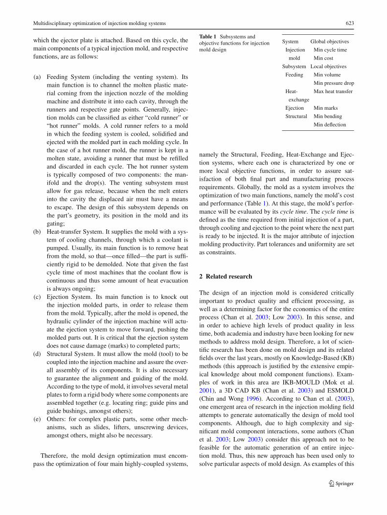
and making injection molds is decreasing. Rather than tak-ing several months, mold design must now be accomplishedin a matter of 2–4 weeks, depending on part complexity.Additionally, during the mold design process, customersoftentimes impose several changes to the plastic part geom-etry and other attributes, requiring fast modifications of themold. Therefore, molds makers are compelled to shortenboth lead times and cost, as well to accomplish higher lev-els of mold performance. This will only be possible withnew design approaches. For all the reasons previously men-tioned, a framework based on MDO, that aims to optimizethe mold design as a system, was developed. The maindesign loop of the developed framework, where processintegration is made by blocks representing its individualmodules (Fig. 3), starts with a geometrical configurationof the initial mold solution, designed according to bestpractice guidelines. Then, the Geometry handler modulecalculates the geometrical and physical dimensions thatwill be used in the following steps and creates the Para-solid file needed by the subsequent analysis. Phenomenaanalyses are, at this stage, carried out by some analysiscodes that use simplified mathematical models to character-ize the main injection molding modules: the Structural, the
Design loop
Mold cost
Subsystems characteristics, Mold size
Feeding subsystem
Heat-exchangesubsystem
Thermal and Rheological(Simplified vs high-fidelity models)
Cycle time, Vfeed, Pressure Deflection, Mold size
Structural
Structural subsystem Ejection subsystem
Mechanical
Marks
New subsystems geometry(parasolid, meshing)
Initial/Old subsystemsgeometry
Subsystem characteristics
Cycle time, Vfeed, Pressure,Deflection, Marks
Fig. 3 Framework process integration
Multidisciplinary optimization of injection molding systems 625
Symbol Designation Symbol Designation Symbol Designation
1.1 t inj Time of injection 2.20 X i Final distance on X coordinate for plate i 4.1 (x0,y0)c Initial Coordinates line i
1.2 Pinj Injection pressure 2.21 YiFinal distance on Y coordinate for plate i
4.2 (xh,yh)c Final Coordinates line i
1.3 typeMold Type of mold 2.22 InsX Distance on X coordinate of cavity insert
4.3 nturns Number of changes in position of cooling channel
1.4 Positionmolding Position of molding on the partition plane
2.23 InsY Distance on Y coordinate of cavity insert
4.4 ncool Number of cooling channels
1.5 typeRunner Type of runner 3.2 l Sprue Length of sprue 4.5 dcool Diameter of cooling channel
1.6 Tmold Temperature of mold 3.3 dSprue Diameter of sprue 4.6 Zcool Distance on Z from cavity surface to the center of cooling line
1.7 Partline Parting line 3.6 dRunner Diameter of runner 4.7 Pitchcool Pitch betwen cooling channels
2.1 Xmold Distance of mold on X coordinate
3.7 l Runner Length of runner 5.1 nPins Number of ejection elements
2.2 Ymold Distance mold on Y coordinate
3.8 typeGate Type of gate 5.2 (x,y)p Position of ejection element p
2.4 nplates Number of plates 3.9 dGate Diameter of gate 5.3 dPins Diameter of ejection element
2.5 Zi Final distance on Zcoordinate for plate i
3.10 l Gate Length gate 5.5 lPins Length of ejection element
2.18 lRet Lenght of return elements 3.11 (x,y,z)g Position of each gate 5.6 dRelease Distance of part’s release 2.19 dRet Diameter of return elements 3.12 nGates Number of gates
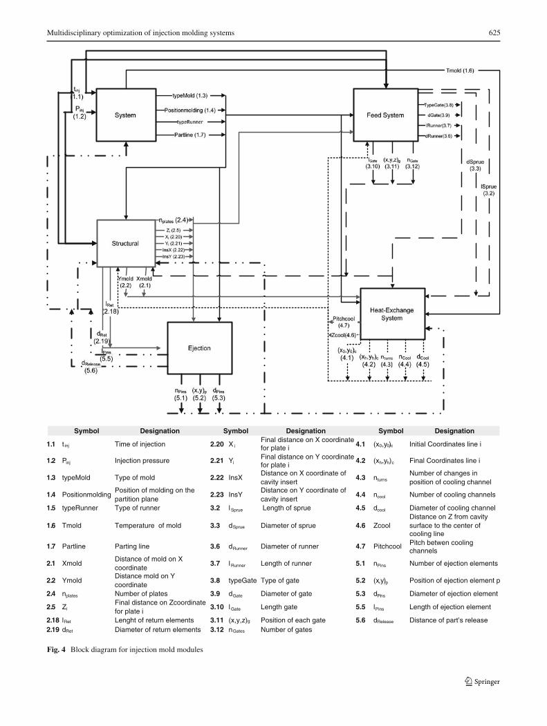
Fig. 4 Block diagram for injection mold modules
626 I. Ferreira et al.
Feeding, the Ejection and the Heat-Exchange subsystems.Later, as future research, these phenomena will be model bymore accurate and realistic approximations through the inte-gration of high-fidelity numerical models (e.g. Moldflowcode—www.moldflow.com).
The system level of this framework involves the initialdesign decisions, such as type of mold, type of feedingsystem, etc. and the integration of the functional mod-ules as interlinked subsystems. The respective inputs andoutputs of each module were determined (Fig. 4), and ablock diagram was built in order to identify the feedfor-ward and feedback paths between the different modules. Itis important to note that the mapping is generic and wasestablished independently of specific plastic part and injec-tion machine characteristics (i.e. these modules and theirrelations are present in every mold design problem). Thisapproach allows the mathematical formulation of the molddesign as a multidisciplinary system design problem. Themultidisciplinary processes considered were rheological,which seeks to model and evaluate the mold filling pro-cess, thermal, encompassing heat transfer, mechanical,concerning the mold’s physical movements, and, finally,structural (mainly represented by the number of plates anddimensions of each plate) aiming to minimize the mold’sdeformation induced by compressive and bending stresses.Some assumptions have been made to simplify this MDOapproach to injection mold design. For example, issues likethe spatial collisions between some of the mold’s elements(e.g. pins, cooling lines, fixing elements, venting, amongstothers), as well as the design of more complex elements, likeslides and lifters, have not been taken into account. Also, areliable cost model (both for design and tool cost, as well aspart manufacturing cost) has not yet been developed. Forthis reason, at the present stage the mold design will beoptimized for minimum cycle time. In order to undertakea first multi-objective optimization, the cycle time, as welltwo local objectives, namely, the volume of feeding systemand the injection pressure drop, will be used as indicators ofthe mold’s performance.
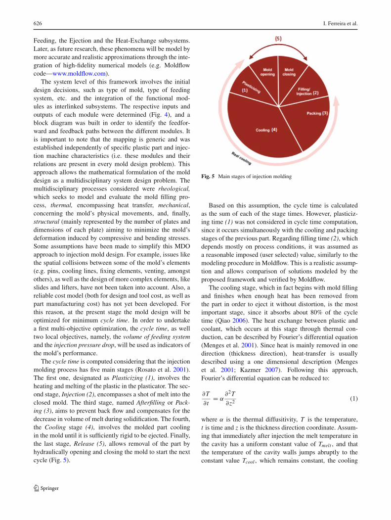
The cycle time is computed considering that the injectionmolding process has five main stages (Rosato et al. 2001).The first one, designated as Plasticizing (1), involves theheating and melting of the plastic in the plasticator. The sec-ond stage, Injection (2), encompasses a shot of melt into theclosed mold. The third stage, named Afterfilling or Pack-ing (3), aims to prevent back flow and compensates for thedecrease in volume of melt during solidification. The fourth,the Cooling stage (4), involves the molded part coolingin the mold until it is sufficiently rigid to be ejected. Finally,the last stage, Release (5), allows removal of the part byhydraulically opening and closing the mold to start the nextcycle (Fig. 5).
Fig. 5 Main stages of injection molding
Based on this assumption, the cycle time is calculatedas the sum of each of the stage times. However, plasticiz-ing time (1) was not considered in cycle time computation,since it occurs simultaneously with the cooling and packingstages of the previous part. Regarding filling time (2), whichdepends mostly on process conditions, it was assumed asa reasonable imposed (user selected) value, similarly to themodeling procedure in Moldflow. This is a realistic assump-tion and allows comparison of solutions modeled by theproposed framework and verified by Moldflow.
The cooling stage, which in fact begins with mold fillingand finishes when enough heat has been removed fromthe part in order to eject it without distortion, is the mostimportant stage, since it absorbs about 80% of the cycletime (Qiao 2006). The heat exchange between plastic andcoolant, which occurs at this stage through thermal con-duction, can be described by Fourier’s differential equation(Menges et al. 2001). Since heat is mainly removed in onedirection (thickness direction), heat-transfer is usuallydescribed using a one dimensional description (Mengeset al. 2001; Kazmer 2007). Following this approach,Fourier’s differential equation can be reduced to:
∂T
∂t= α
∂2T
∂z2(1)
where α is the thermal diffusitivity, T is the temperature,t is time and z is the thickness direction coordinate. Assum-ing that immediately after injection the melt temperature inthe cavity has a uniform constant value of Tmelt , and thatthe temperature of the cavity walls jumps abruptly to theconstant value Tcool , which remains constant, the cooling
Multidisciplinary optimization of injection molding systems 627
time (4) for a strip plane geometry can be estimated usingthe previous equation, leading to the following expression(Kazmer 2007):
tcool = s2
π2αln
(8
π2
(Tmelt − Tcool)
(Tdemol − Tcool)
)(2)
where s is the wall thickness assuming the plastic part asa strip plate, Tmelt is the melting temperature, Tcool is thecavity wall temperature and Tdemol is the mean demoldingtemperature (the temperature at which the material is rigidenough to be ejected). Assuming that the time required forcooling the feeding system is longer than the time neededto cool the part itself (this is a necessary constraint toavoid premature freezing inside the part which could leadto incomplete filling), the bottleneck of the cooling pro-cess will be the feeding system, or more precisely the Sprue(biggest component of this subsystem, since it must sup-ply the entire feeding system with enough melt). Due to theconical shape of this component (Menges et al. 2001), theprevious generic equation (1) must be replaced by:
tcool = d2Sprue
23.1αln
(0.692
(Tmelt − Tcool)
(Tdemol − Tcool)
)(3)
where d Sprue is the sprue mean diameter. Note that both (2)and (3) are solutions of (1), but (2) is valid for strip plates,while (3) assumes a cylindrical geometry.
The post-filling time (3), generally known as packingtime, is determined based on the gate dimensions (Kazmer2007). The packing stage has as its main function to forceadditional melt into the cavity, after the filling stage, in orderto compensate for volumetric shrinkage of the part and toavoid any back flow of melt. Therefore, if the gate is toosmall the melt will prematurely solidify and no additionalmaterial will enter into the cavity (packing does not occur).If it is too large, the gate will take more time than neces-sary to solidify, which results in a longer pack time. Thus,the packing stage time must end with the gate freeze-off.The necessary cooling time for gates (i.e. gate freeze-off) isdetermined using an expression according to (4):
tpack = d2Gate
23.1αln
(0.692
(Tmelt − Tcool)
(Tdemol − Tcool)
)(4)
where dGate is the gate diameter.The mold opening time is calculated as the ratio of the
mold opening distance (designated as dRelease) and the moldopening velocity. The velocity of mold opening (vopen) wasbased on Kazmer’s regression (Kazmer 2007: page 129),which states that the velocity is a logarithmic function ofthe ratio between the clamping force (i.e. the force needed
to hold the mold closed expressed in tons) and a referenceforce of 1 ton (5).
vopen [mm/s] = 184 + 13log
(Fclamp
Fre f
)(5)
Where vopen is expresses in millimeters per second. Sincethe clamping force can be computed as the injection pres-sure (Pinj ) times the projected area of molding (Aproj ), themold opening time can be calculated using (6).
topen = dRelease1 × 103
184 + 13log(
Pinj Aproj 1×10⁻³
9.8Fre f
) (6)
In this work, it is assumed that the time to open is equalto the time to close the mold (i.e. the time to release the part(5) is equal to two times the opening time). In summary, thetheoretical cycle time (objective function), which involvesthe summation of cooling time (expressed by the necessarytime to cool the Sprue) plus the packing time (which is lim-ited by gate’s freezing), and, finally, the time to open andto close the mold, that can be described by the followingexpression:
Cycle time =[dSprue + tan
(αSprueπ
180
)lSprue
]2
23.1α
× ln
(0.692
(Tmelt − Tcool)
(Tdemol − Tcool)
)
+ d2gate
23.1αln
(0.692
(Tmelt − Tcool)
(Tdemol − Tcool)
)
+ 2 × dRelease1 × 103
184 + 13log(
Pinj Aproj 1×10⁻³
9.8Fre f
) (7)
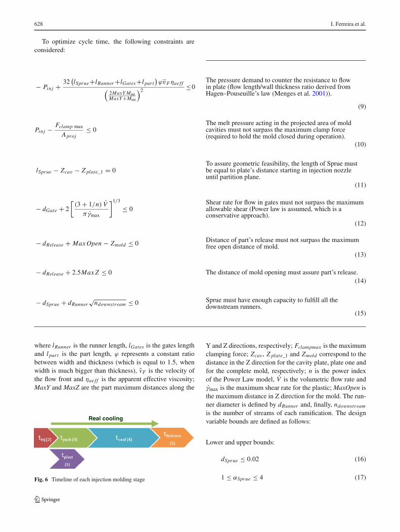
Considering Fig. 5 the plasticizing time (1) is neglectedsince it occurs in parallel with the other processes for thepreceding part. Also, the injection time (2) is very smallcompared to the other times in (7) and is assumed as a con-stant value (it was assumed 1.5 s for filing time). Finally,the cooling time (4) is not the total time doing which cool-ing occurs, but only the excess cooling time required for theSprue to freeze (Fig. 6).
Note that d Sprue can be determined based on the geomet-rical characteristics of the Sprue as:
d Sprue = dSprue + tan(αSprueπ
180
)lSprue (8)
where dSprue is the initial diameter, lSprue is the length andαSprue is the draft angle.
628 I. Ferreira et al.
To optimize cycle time, the following constraints areconsidered:
− Pinj + 32(lSprue+lRunner +lGates +l part
)ϕvFηae ff(
2MaxY MintMaxY+Mint
)2≤0
The pressure demand to counter the resistance to flowin plate (flow length/wall thickness ratio derived fromHagen–Pouseuille’s law (Menges et al. 2001)).
(9)
Pinj − Fclamp max
Aproj≤ 0
The melt pressure acting in the projected area of moldcavities must not surpass the maximum clamp force(required to hold the mold closed during operation).
(10)
lSprue − Zcav − Z plate_1 = 0To assure geometric feasibility, the length of Sprue mustbe equal to plate’s distance starting in injection nozzleuntil partition plane.
(11)
− dGate + 2
[(3 + 1/n) V̇
πγ̇max
]1/3
≤ 0Shear rate for flow in gates must not surpass the maximumallowable shear (Power law is assumed, which is aconservative approach).
(12)
− dRelease + Max Open − Zmold ≤ 0 Distance of part’s release must not surpass the maximumfree open distance of mold.
(13)
− dRelease + 2.5Max Z ≤ 0 The distance of mold opening must assure part’s release.(14)
− dSprue + dRunner√
ndownstream ≤ 0 Sprue must have enough capacity to fulfill all thedownstream runners.
(15)
where lRunner is the runner length, lGates is the gates lengthand l part is the part length, ϕ represents a constant ratiobetween width and thickness (which is equal to 1.5, whenwidth is much bigger than thickness), v̄F is the velocity ofthe flow front and ηae ff is the apparent effective viscosity;MaxY and MaxZ are the part maximum distances along the
Real cooling
Fig. 6 Timeline of each injection molding stage
Y and Z directions, respectively; Fclampmax is the maximumclamping force; Zcav, Z plate_1 and Zmold correspond to thedistance in the Z direction for the cavity plate, plate one andfor the complete mold, respectively; n is the power indexof the Power Law model, V̇ is the volumetric flow rate andγ̇max is the maximum shear rate for the plastic; MaxOpen isthe maximum distance in Z direction for the mold. The run-ner diameter is defined by dRunner and, finally, ndownstream
is the number of streams of each ramification. The designvariable bounds are defined as follows:
Lower and upper bounds:
dSprue ≤ 0.02 (16)
1 ≤ αSprue ≤ 4 (17)
Multidisciplinary optimization of injection molding systems 629
0.0005 ≤ dGate ≤ 0.003 (18)
0.0005 ≤ lGate ≤ 0.001 (19)
Additional Constraints (for single objective optimization):
Volume of feeding system <= 0.3Vpart (20)
Pressure drop <= 0.5Pinj (21)
where Vpart is the total volume of the molded plastic part.The minimization of wasted material is defined based onthe volume of the feeding system (cold runner system),computed by:
Vf eed =π
4
(d̄2
SpruelSprue+ndownstreamnRami f d2Runner lRunner
+ d2GatelGatesnGates
)(22)
where nRami f and nGates are the number of ramificationsof the runner and number of gates per each plastic part,respectively.
The minimization of pressure drop is determined usingthe equation of motion, where the force due to pressure dropalong the flow (caused by the viscous flow in the channel)must be equal to the force resulting from shear stresses.Both occur along the length of the melt flow. Therefore,using the Power Law Model, which has been shown toprovide accurate results, that states that viscosity is an expo-nential function of the shear rate, it is possible to estimatepressure drop as a function of the volumetric flow rate. Fora channel with a circular shape, the pressure drop estimateis given by:
�P = 4kL
D
⎡⎣
(3 + 1
n
)V̇
π( D
2
)3
⎤⎦
n
(23)
where k is the viscosity evaluated at a shear rate of onereciprocal second, n is the power law index, V̇ is the volu-metric flow rate, D is diameter and L is the channel length.Based on this expression, the total pressure drop caused bythe feeding system is established as:
�P = 4klSprue
d Sprue
⎛⎜⎝
(3 + 1
n
)V̇
π(
d Sprue2
)3
⎞⎟⎠
n
+ 4klRunner
dRunner
⎛⎜⎝
(3 + 1
n
)V̇
π(
dRunner2
)3
⎞⎟⎠
n
+ 4klGates
dGates
⎛⎜⎝
(3 + 1
n
)V̇
π(
dGates2
)3
⎞⎟⎠
n
(24)
The mathematical problem for the design of an injectionmold is therefore defined.
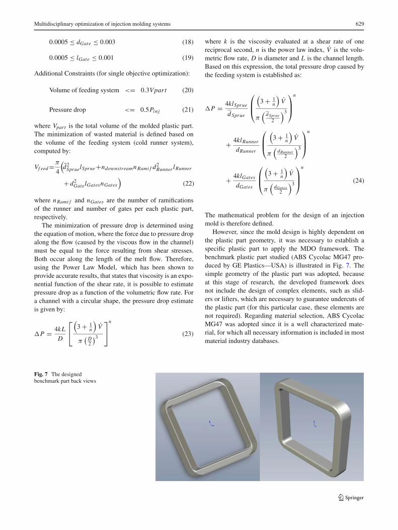
However, since the mold design is highly dependent onthe plastic part geometry, it was necessary to establish aspecific plastic part to apply the MDO framework. Thebenchmark plastic part studied (ABS Cycolac MG47 pro-duced by GE Plastics—USA) is illustrated in Fig. 7. Thesimple geometry of the plastic part was adopted, becauseat this stage of research, the developed framework doesnot include the design of complex elements, such as slid-ers or lifters, which are necessary to guarantee undercuts ofthe plastic part (for this particular case, these elements arenot required). Regarding material selection, ABS CycolacMG47 was adopted since it is a well characterized mate-rial, for which all necessary information is included in mostmaterial industry databases.
Fig. 7 The designedbenchmark part back views
630 I. Ferreira et al.
4 Single objective optimization
In a first optimization procedure, one single objective func-tion was considered, namely cycle time minimization. Theremaining objective functions, concerning the Structural,Feeding, Heat-Exchange and Ejection subsystems, wereincluded in the model as constraints. Cost minimization isnot yet included in the model, since this variable is mostly afunction of part’s size and complexity, which at this stagewere considered as fixed parameters. To undertake cycletime optimization as a single objective function, a gradient-based approach was adopted. In order to select the mostadequate gradient-based algorithm, some important charac-teristics of injection mold design were considered, namelythe number and type of design variables and constraints, thefeasibility of design space, the type of initial solution andthe adequate simulation runtime. Based on these factors,and following iSIGHT criteria (iSIGHT-FD 2007), a briefcharacterization of this mold design problem was obtained(Table 2).
In this context, and considering that certain optimizationtechniques do not perform adequately in the presence ofequality constraints (e.g., Method of Feasible Directions—CONMIN) and others are better adapted to handle problemswith infeasible initial designs (e.g. penalty-based optimiza-tion techniques), some gradients based methods can beexcluded. Moreover, since the mold design problem isa large-scale nonlinear programming problem (NLP) withmostly smooth non-convex nonlinear functions (there aresome constraints and at least one objective that is a nonsmooth nonlinear function of the decision variables) thechoice of optimizer can be made judiciously. Thus, the mostwidely used and effective methods are Generalized ReducedGradient (GRG) and Sequential Quadratic Programming(SQP). One special advantage of the GRG method is thatthe extension for determining the solution of large sparseproblems is conceptually simple. The availability and user-
Table 2 Main characteristics of mold design mathematical problemformulation
Factors
Number of design variables High (>20)
Number of constraints Low (<1,000)
Type of design variables Real; integer and categorical
Objective/constraints functions Non linear
Constraints type Inequality/equality
Feasible space Non-convex and discontinuous
Initial point Feasible
Simulation run time Short (see Table 7)
friendly nature of the GRG2 method (Lasdon et al. 1978),justified its adoption to undertake this task.
By using GRG2, the optimal solution determined corre-sponds to a cycle time reduction of 41.7%, as comparedwith the initially assumed (feasible) solution (Table 3).This initial solution was established according the practi-cal guidelines followed by the injection molding industry,which can be observed in mold designer manuals (Centimfe2003).
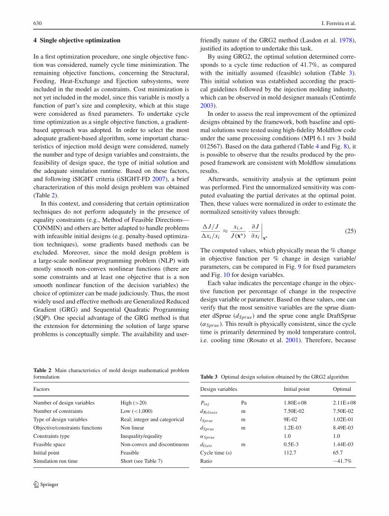
In order to assess the real improvement of the optimizeddesigns obtained by the framework, both baseline and opti-mal solutions were tested using high-fidelity Moldflow codeunder the same processing conditions (MPI 6.1 rev 3 build012567). Based on the data gathered (Table 4 and Fig. 8), itis possible to observe that the results produced by the pro-posed framework are consistent with Moldflow simulationsresults.
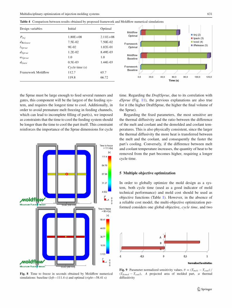
Afterwards, sensitivity analysis at the optimum pointwas performed. First the unnormalized sensitivity was com-puted evaluating the partial derivates at the optimal point.Then, these values were normalized in order to estimate thenormalized sensitivity values through:
�J/J
�xi/xi≈ xi,∗
J (x∗)· ∂ J
∂xi
∣∣∣∣x∗
(25)
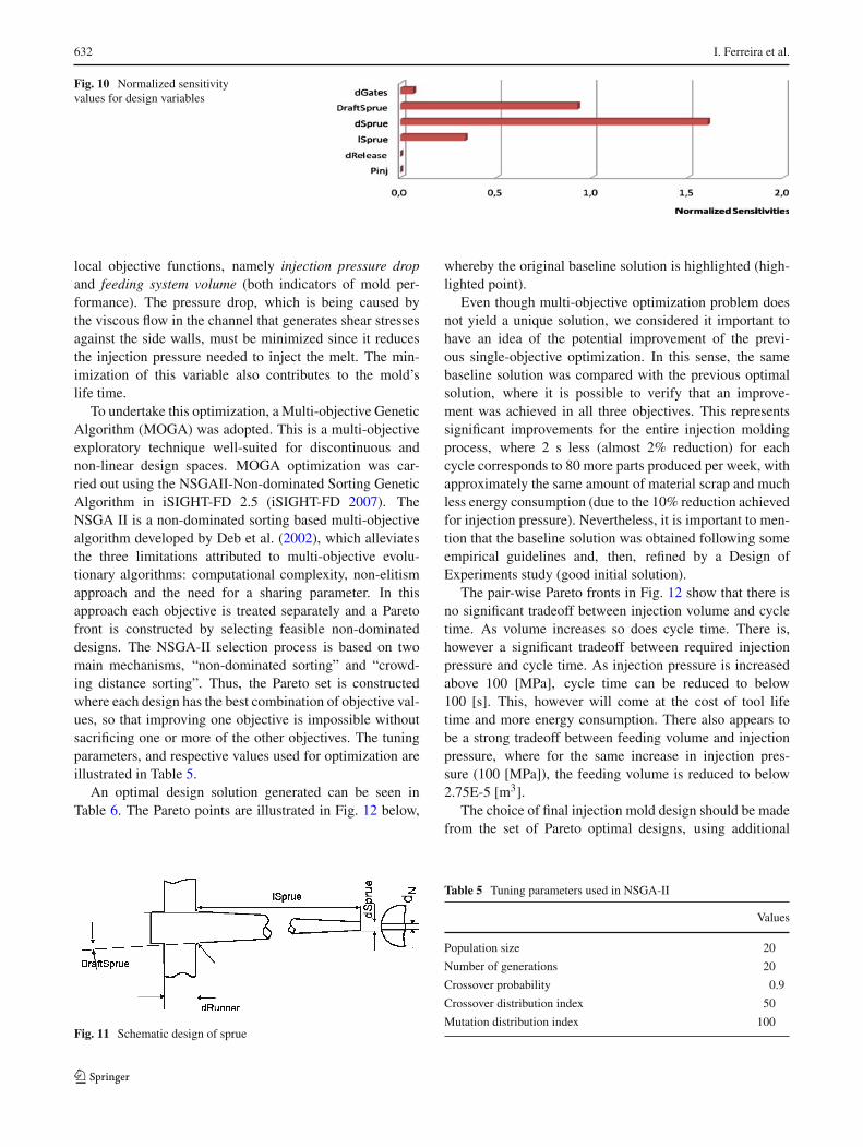
The computed values, which physically mean the % changein objective function per % change in design variable/parameters, can be compared in Fig. 9 for fixed parametersand Fig. 10 for design variables.
Each value indicates the percentage change in the objec-tive function per percentage of change in the respectivedesign variable or parameter. Based on these values, one canverify that the most sensitive variables are the sprue diam-eter dSprue (dSprue) and the sprue cone angle DraftSprue(αSprue). This result is physically consistent, since the cycletime is primarily determined by mold temperature control,i.e. cooling time (Rosato et al. 2001). Therefore, because
Table 3 Optimal design solution obtained by the GRG2 algorithm
Design variables Initial point Optimal
Pinj Pa 1.80E+08 2.11E+08
dRelease m 7.50E-02 7.50E-02
lSprue m 9E-02 1.02E-01
dSprue m 1.2E-03 8.49E-03
αSprue 1.0 1.0
dGate m 0.5E-3 1.44E-03
Cycle time (s) 112.7 65.7
Ratio −41.7%
Multidisciplinary optimization of injection molding systems 631
Table 4 Comparison between results obtained by proposed framework and Moldflow numerical simulations
the Sprue must be large enough to feed several runners andgates, this component will be the largest of the feeding sys-tem, and requires the longest time to cool. Additionally, inorder to avoid premature melt freezing in feeding channels,which can lead to incomplete filling of part(s), we imposedas constraints that the time to cool the feeding system shouldbe longer than the time to cool the part itself. This constraintreinforces the importance of the Sprue dimensions for cycle
Fig. 8 Time to freeze in seconds obtained by Moldflow numericalsimulations: baseline (left—111.4 s) and optimal (right—58.41 s)
time. Regarding the DraftSprue, due to its correlation withdSprue (Fig. 11), the previous explanations are also truefor it (the higher DraftSprue, the higher the final volume ofthe Sprue).
Regarding the fixed parameters, the most sensitive arethe thermal diffusivity and the ratio between the differenceof the melt and coolant and the demolded and coolant tem-peratures. This is also physically consistent, since the largerthe thermal diffusivity the more heat is transferred betweenthe melt and the coolant, and consequently the faster thepart’s cooling. Conversely, if the difference between meltand coolant temperature increases, the quantity of heat to beremoved from the part becomes higher, requiring a longercycle time.
5 Multiple objective optimization
In order to globally optimize the mold design as a sys-tem, both cycle time (used as a good indicator of moldtechnical performance) and mold cost should be used asobjective functions (Table 1). However, in the absence ofa reliable cost model, the multi-objective optimization per-formed considers one global objective, cycle time, and two
Fig. 9 Parameter normalized sensitivity values. θ = (Tmelt − Tcool ) /
(Tdemol − Tcool ), A projected area of molded part, α thermaldiffusitivity
632 I. Ferreira et al.
Fig. 10 Normalized sensitivityvalues for design variables
local objective functions, namely injection pressure dropand feeding system volume (both indicators of mold per-formance). The pressure drop, which is being caused bythe viscous flow in the channel that generates shear stressesagainst the side walls, must be minimized since it reducesthe injection pressure needed to inject the melt. The min-imization of this variable also contributes to the mold’slife time.
To undertake this optimization, a Multi-objective GeneticAlgorithm (MOGA) was adopted. This is a multi-objectiveexploratory technique well-suited for discontinuous andnon-linear design spaces. MOGA optimization was car-ried out using the NSGAII-Non-dominated Sorting GeneticAlgorithm in iSIGHT-FD 2.5 (iSIGHT-FD 2007). TheNSGA II is a non-dominated sorting based multi-objectivealgorithm developed by Deb et al. (2002), which alleviatesthe three limitations attributed to multi-objective evolu-tionary algorithms: computational complexity, non-elitismapproach and the need for a sharing parameter. In thisapproach each objective is treated separately and a Paretofront is constructed by selecting feasible non-dominateddesigns. The NSGA-II selection process is based on twomain mechanisms, “non-dominated sorting” and “crowd-ing distance sorting”. Thus, the Pareto set is constructedwhere each design has the best combination of objective val-ues, so that improving one objective is impossible withoutsacrificing one or more of the other objectives. The tuningparameters, and respective values used for optimization areillustrated in Table 5.
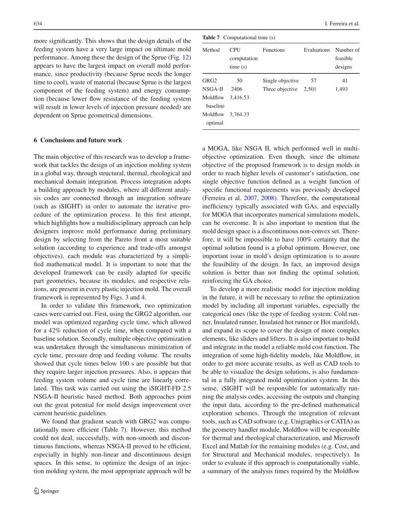
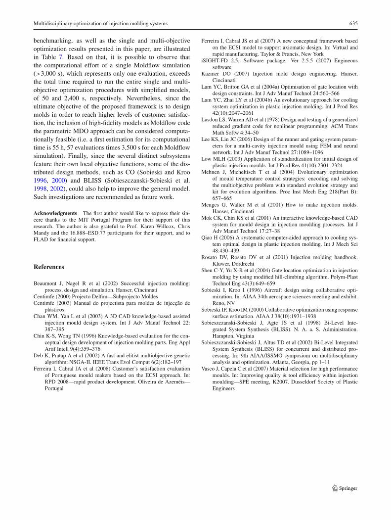
An optimal design solution generated can be seen inTable 6. The Pareto points are illustrated in Fig. 12 below,
Fig. 11 Schematic design of sprue
whereby the original baseline solution is highlighted (high-lighted point).
Even though multi-objective optimization problem doesnot yield a unique solution, we considered it important tohave an idea of the potential improvement of the previ-ous single-objective optimization. In this sense, the samebaseline solution was compared with the previous optimalsolution, where it is possible to verify that an improve-ment was achieved in all three objectives. This representssignificant improvements for the entire injection moldingprocess, where 2 s less (almost 2% reduction) for eachcycle corresponds to 80 more parts produced per week, withapproximately the same amount of material scrap and muchless energy consumption (due to the 10% reduction achievedfor injection pressure). Nevertheless, it is important to men-tion that the baseline solution was obtained following someempirical guidelines and, then, refined by a Design ofExperiments study (good initial solution).
The pair-wise Pareto fronts in Fig. 12 show that there isno significant tradeoff between injection volume and cycletime. As volume increases so does cycle time. There is,however a significant tradeoff between required injectionpressure and cycle time. As injection pressure is increasedabove 100 [MPa], cycle time can be reduced to below100 [s]. This, however will come at the cost of tool lifetime and more energy consumption. There also appears tobe a strong tradeoff between feeding volume and injectionpressure, where for the same increase in injection pres-sure (100 [MPa]), the feeding volume is reduced to below2.75E-5 [m3].
The choice of final injection mold design should be madefrom the set of Pareto optimal designs, using additional
Table 5 Tuning parameters used in NSGA-II
Values
Population size 20
Number of generations 20
Crossover probability 0.9
Crossover distribution index 50
Mutation distribution index 100
Multidisciplinary optimization of injection molding systems 633
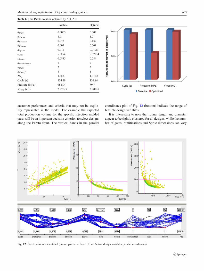
Table 6 One Pareto solution obtained by NSGA-II
customer preferences and criteria that may not be explic-itly represented in the model. For example the expectedtotal production volume for the specific injection moldedparts will be an important decision criterion to select designsalong the Pareto front. The vertical bands in the parallel
coordinates plot of Fig. 12 (bottom) indicate the range offeasible design variables.
It is interesting to note that runner length and diameterappear to be tightly clustered for all designs, while the num-ber of gates, ramifications and Sprue dimensions can vary
Fig. 12 Pareto solutions identified (above: pair-wise Pareto front, below: design variables parallel coordinates)
634 I. Ferreira et al.
more significantly. This shows that the design details of thefeeding system have a very large impact on ultimate moldperformance. Among these the design of the Sprue (Fig. 12)appears to have the largest impact on overall mold perfor-mance, since productivity (because Sprue needs the longertime to cool), waste of material (because Sprue is the largestcomponent of the feeding system) and energy consump-tion (because lower flow resistance of the feeding systemwill result in lower levels of injection pressure needed) aredependent on Sprue geometrical dimensions.
6 Conclusions and future work
The main objective of this research was to develop a frame-work that tackles the design of an injection molding systemin a global way, through structural, thermal, rheological andmechanical domain integration. Process integration adoptsa building approach by modules, where all different analy-sis codes are connected through an integration software(such as iSIGHT) in order to automate the iterative pro-cedure of the optimization process. In this first attempt,which highlights how a multidisciplinary approach can helpdesigners improve mold performance during preliminarydesign by selecting from the Pareto front a most suitablesolution (according to experience and trade-offs amongstobjectives), each module was characterized by a simpli-fied mathematical model. It is important to note that thedeveloped framework can be easily adapted for specificpart geometries, because its modules, and respective rela-tions, are present in every plastic injection mold. The overallframework is represented by Figs. 3 and 4.
In order to validate this framework, two optimizationcases were carried out. First, using the GRG2 algorithm, ourmodel was optimized regarding cycle time, which allowedfor a 42% reduction of cycle time, when compared with abaseline solution. Secondly, multiple objective optimizationwas undertaken through the simultaneous minimization ofcycle time, pressure drop and feeding volume. The resultsshowed that cycle times below 100 s are possible but thatthey require larger injection pressures. Also, it appears thatfeeding system volume and cycle time are linearly corre-lated. This task was carried out using the iSIGHT-FD 2.5NSGA-II heuristic based method. Both approaches pointout the great potential for mold design improvement overcurrent heuristic guidelines.
We found that gradient search with GRG2 was compu-tationally more efficient (Table 7). However, this methodcould not deal, successfully, with non-smooth and discon-tinuous functions, whereas NSGA-II proved to be efficient,especially in highly non-linear and discontinuous designspaces. In this sense, to optimize the design of an injec-tion molding system, the most appropriate approach will be
Table 7 Computational time (s)
Method CPU Functions Evaluations Number of
computation feasible
time (s) designs
GRG2 50 Single objective 57 41
NSGA-II 2406 Three objective 2,501 1,493
Moldflow 3,416.53
baseline
Moldflow 3,764.33
optimal
a MOGA, like NSGA II, which performed well in multi-objective optimization. Even though, since the ultimateobjective of the proposed framework is to design molds inorder to reach higher levels of customer’s satisfaction, onesingle objective function defined as a weight function ofspecific functional requirements was previously developed(Ferreira et al. 2007, 2008). Therefore, the computationalinefficiency typically associated with GAs, and especiallyfor MOGA that incorporates numerical simulations models,can be overcome. It is also important to mention that themold design space is a discontinuous non-convex set. There-fore, it will be impossible to have 100% certainty that theoptimal solution found is a global optimum. However, oneimportant issue in mold’s design optimization is to assurethe feasibility of the design. In fact, an improved designsolution is better than not finding the optimal solution,reinforcing the GA choice.
To develop a more realistic model for injection moldingin the future, it will be necessary to refine the optimizationmodel by including all important variables, especially thecategorical ones (like the type of feeding system: Cold run-ner, Insulated runner, Insulated hot runner or Hot manifold),and expand its scope to cover the design of more complexelements, like sliders and lifters. It is also important to buildand integrate in the model a reliable mold cost function. Theintegration of some high-fidelity models, like Moldflow, inorder to get more accurate results, as well as CAD tools tobe able to visualize the design solutions, is also fundamen-tal in a fully integrated mold optimization system. In thissense, iSIGHT will be responsible for automatically run-ning the analysis codes, accessing the outputs and changingthe input data, according to the pre-defined mathematicalexploration schemes. Through the integration of relevanttools, such as CAD software (e.g. Unigraphics or CATIA) asthe geometry handler module, Moldflow will be responsiblefor thermal and rheological characterization, and MicrosoftExcel and Matlab for the remaining modules (e.g. Cost, andfor Structural and Mechanical modules, respectively). Inorder to evaluate if this approach is computationally viable,a summary of the analysis times required by the Moldflow
Multidisciplinary optimization of injection molding systems 635
benchmarking, as well as the single and multi-objectiveoptimization results presented in this paper, are illustratedin Table 7. Based on that, it is possible to observe thatthe computational effort of a single Moldflow simulation(>3,000 s), which represents only one evaluation, exceedsthe total time required to run the entire single and multi-objective optimization procedures with simplified models,of 50 and 2,400 s, respectively. Nevertheless, since theultimate objective of the proposed framework is to designmolds in order to reach higher levels of customer satisfac-tion, the inclusion of high-fidelity models as Moldflow codethe parametric MDO approach can be considered computa-tionally feasible (i.e. a first estimation for its computationaltime is 55 h, 57 evaluations times 3,500 s for each Moldflowsimulation). Finally, since the several distinct subsystemsfeature their own local objective functions, some of the dis-tributed design methods, such as CO (Sobieski and Kroo1996, 2000) and BLISS (Sobieszczanski-Sobieski et al.1998, 2002), could also help to improve the general model.Such investigations are recommended as future work.
Acknowledgments The first author would like to express their sin-cere thanks to the MIT Portugal Program for their support of thisresearch. The author is also grateful to Prof. Karen Willcox, ChrisMandy and the 16.888–ESD.77 participants for their support, and toFLAD for financial support.
References
Beaumont J, Nagel R et al (2002) Successful injection molding:process, design and simulation. Hanser, Cincinnati
Centimfe (2000) Projecto Delfim—Subprojecto MoldesCentimfe (2003) Manual do projectista para moldes de injecção de
plásticosChan WM, Yan L et al (2003) A 3D CAD knowledge-based assisted
injection mould design system. Int J Adv Manuf Technol 22:387–395
Chin K-S, Wong TN (1996) Knowledge-based evaluation for the con-ceptual design development of injection molding parts. Eng ApplArtif Intell 9(4):359–376
Deb K, Pratap A et al (2002) A fast and elitist multiobjective geneticalgorithm: NSGA-II. IEEE Trans Evol Comput 6(2):182–197
Ferreira I, Cabral JA et al (2008) Customer’s satisfaction evaluationof Portuguese mould makers based on the ECSI approach. In:RPD 2008—rapid product development. Oliveira de Azeméis—Portugal
Ferreira I, Cabral JS et al (2007) A new conceptual framework basedon the ECSI model to support axiomatic design. In: Virtual andrapid manufacturing. Taylor & Francis, New York
iSIGHT-FD 2.5, Software package, Ver 2.5.5 (2007) Engineoussoftware
Kazmer DO (2007) Injection mold design engineering. Hanser,Cincinnati
Lam YC, Britton GA et al (2004a) Optimisation of gate location withdesign constraints. Int J Adv Manuf Technol 24:560–566
Lam YC, Zhai LY et al (2004b) An evolutionary approach for coolingsystem optimization in plastic injection molding. Int J Prod Res42(10):2047–2061
Lasdon LS, Warren AD et al (1978) Design and testing of a generalizedreduced gradient code for nonlinear programming. ACM TransMath Softw 4:34–50
Lee KS, Lin JC (2006) Design of the runner and gating system param-eters for a multi-cavity injection mould using FEM and neuralnetwork. Int J Adv Manuf Technol 27:1089–1096
Low MLH (2003) Application of standardization for initial design ofplastic injection moulds. Int J Prod Res 41(10):2301–2324
Mehnen J, Micheltisch T et al (2004) Evolutionary optimizationof mould temperature control strategies: encoding and solvingthe multiobjective problem with standard evolution strategy andkit for evolution algorithms. Proc Inst Mech Eng 218(Part B):657–665
Menges G, Walter M et al (2001) How to make injection molds.Hanser, Cincinnati
Mok CK, Chin KS et al (2001) An interactive knowledge-based CADsystem for mould design in injection moulding processes. Int JAdv Manuf Technol 17:27–38
Qiao H (2006) A systematic computer-aided approach to cooling sys-tem optimal design in plastic injection molding. Int J Mech Sci48:430–439
Rosato DV, Rosato DV et al (2001) Injection molding handbook.Kluwer, Dordrecht
Shen C-Y, Yu X-R et al (2004) Gate location optimization in injectionmolding by using modified hill-climbing algorithm. Polym-PlastTechnol Eng 43(3):649–659
Sobieski I, Kroo I (1996) Aircraft design using collaborative opti-mization. In: AIAA 34th aerospace sciences meeting and exhibit.Reno, NV
Sobieski IP, Kroo IM (2000) Collaborative optimization using responsesurface estimation. AIAA J 38(10):1931–1938
Sobieszczanski-Sobieski J, Agte JS et al (1998) Bi-Level Inte-grated System Synthesis (BLISS). N. A. a. S. Administration.Hampton, Virginia
Sobieszczanski-Sobieski J, Altus TD et al (2002) Bi-Level IntegratedSystem Synthesis (BLISS) for concurrent and distributed pro-cessing. In: 9th AIAA/ISSMO symposium on multidisciplinaryanalysis and optimization. Atlanta, Georgia, pp 1–11
Vasco J, Capela C et al (2007) Material selection for high performancemoulds. In: Improving quality & tool efficiency within injectionmoulding—SPE meeting, K2007. Dusseldorf Society of PlasticEngineers