Embed Size (px)
Citation preview

Multidisciplinary Analysis Workflow
with the FlowSimulator
Lars Reimerx
www.DLR.de • Chart 1 > Multidisciplinary Analysis Workflow with the FlowSimulator > Lars Reimer • Document > October 3rd, 2012
Scientific Day 2012
With contributions of Daniel Vollmer, Gunnar Einnarson, Stefan Görtz, Thomas Gerhold,
Ralf Heinrich, Norbert Kroll, Andreas Michler (all DLR-AS), Markus Ritter, Jens Neumann (all DLR-AE),
Lars-Uwe Hansen (Airbus)
Institute for Aerodynamics & Flow Technology
Department C²A²S²E
Lilienthalplatz 7
38108 Braunschweig
Germany
Outline
• General overview of FlowSimulator
(objectives, concept, etc.)
• Aspects of trim simulations with FS
• Aspects of CFD-CSM coupled simulations with FS
www.DLR.de • Chart 2 > Multidisciplinary Analysis Workflow with the FlowSimulator > Lars Reimer • Document > October 3rd, 2012
focus on
DLR
process
chains

Overall Objective: Accurate Analysis for
Entire Flight Envelope
www.DLR.de • Chart 3 > Multidisciplinary Analysis Workflow with the FlowSimulator > Lars Reimer • ONERA Scientific Day > October 3rd, 2012
coverage: coverage:
Rigid-Body Flight Dynamics
CFD-based Aerodynamics + Mesh defo.
Flight Control System
Structural Elasto-Dynamics
free A/C
Requires Efficient Multidisciplinary HiFi
Simulation Tools

What is FlowSimulator and What Are Its Main
Objectives ?
• Numerical tool box for high-performance multi-
disciplinary simulations
• Designed for efficient massively-parallel in-memory
data exchange between mono-disciplinary codes
• Easy replacement of simulation components
www.DLR.de • Chart 4 > Multidisciplinary Analysis Workflow with the FlowSimulator > Lars Reimer • Document > October 3rd, 2012

What is FlowSimulator Technically ?
(=FSDM)
• devel. by entire FS
community
• open source
• provides parallel
data management
• devel. mainly by
Airbus
• supposed to be
main access layer
for end-users (high-
level classes)
• FS is a bundle of Python modules which work on
a common data structure, i.e. the FSDM
• Python-based scripting layer enables rapid
prototyping of tool chains
www.DLR.de • Chart 5 > Multidisciplinary Analysis Workflow with the FlowSimulator > Lars Reimer • Document > October 3rd, 2012
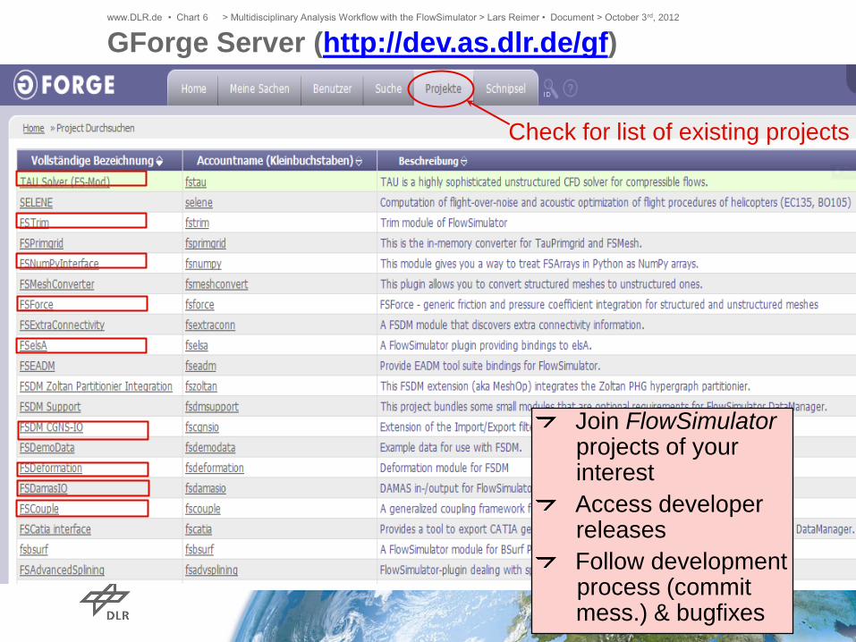
GForge Server (http://dev.as.dlr.de/gf) www.DLR.de • Chart 6 > Multidisciplinary Analysis Workflow with the FlowSimulator > Lars Reimer • Document > October 3rd, 2012
Check for list of existing projects
Join FlowSimulator projects of your interest
Access developer releases
Follow development process (commit mess.) & bugfixes

• NO horizontal data exchange between simulation components
in-memory data exchange
TAU.ChainRun()
retrieves
mesh
(+ solution)
retrieves
mesh
(+ solution)
iterate
FS’ Design Dogma for Replaceability of Sim. Components
www.DLR.de • Chart 7 > Multidisciplinary Analysis Workflow with the FlowSimulator > Lars Reimer • Document > October 3rd, 2012

Trim Simulations with
FlowSimulator
www.DLR.de • Chart 8 > Multidisciplinary Analysis Workflow with the FlowSimulator > Lars Reimer • Document > October 3rd, 2012

General Longitudinal Trim Process
Initial CFD solution
Computation of Jacobian:
• Perturbation of control variable
(here AoA, HTP)
• Transfer perturbed control variable into
BCs/mesh
• Compute CFD sol. for perturbed state
Compute Newton step (here for AoA & HTP)
Transfer altered control variable into
BCs/mesh
Compute CFD solution
While trim condition not fulfilled
(here CL=CL,Target, CMy=0):
LO
OP
If Jacobian is to be updated:
Challenge:
Rotation of HTP
while preserving
the fuselage
geometry
www.DLR.de • Chart 9 > Multidisciplinary Analysis Workflow with the FlowSimulator > Lars Reimer • Document > October 3rd, 2012
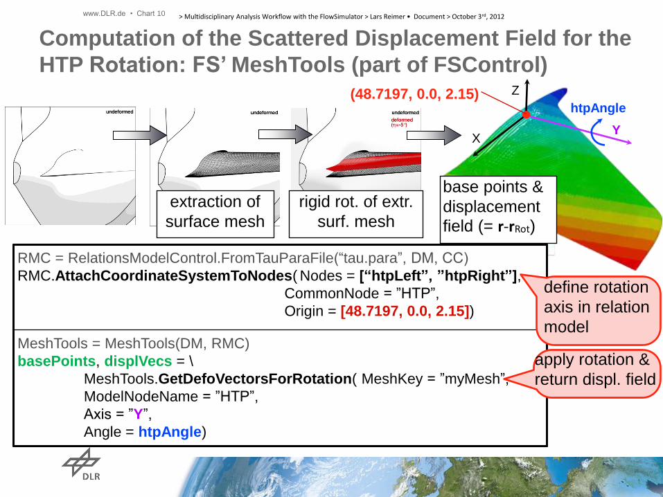
Computation of the Scattered Displacement Field for the
HTP Rotation: FS’ MeshTools (part of FSControl)
extraction of
surface mesh
rigid rot. of extr.
surf. mesh
Y
Z
X
htpAngle (48.7197, 0.0, 2.15)
RMC = RelationsModelControl.FromTauParaFile(“tau.para”, DM, CC)
RMC.AttachCoordinateSystemToNodes( Nodes = [“htpLeft”, ”htpRight”],
CommonNode = ”HTP”,
Origin = [48.7197, 0.0, 2.15])
MeshTools = MeshTools(DM, RMC)
basePoints, displVecs = \
MeshTools.GetDefoVectorsForRotation( MeshKey = ”myMesh”,
ModelNodeName = ”HTP”,
Axis = ”Y”,
Angle = htpAngle)
base points &
displacement
field (= r-rRot)
define rotation
axis in relation
model
apply rotation &
return displ. field
www.DLR.de • Chart 10 > Multidisciplinary Analysis Workflow with the FlowSimulator > Lars Reimer • Document > October 3rd, 2012

HTP rot. angle Y
Z
X
RZW1m
Example A350-1000:
- HTP rot. in trim computations
- Prescribed displacement field
corresponding to rigid HTP rot.:
stretching
compression
Problem with Mesh Deformation at HTP-Fuselage
Intersection
www.DLR.de • Chart 11 > Multidisciplinary Analysis Workflow with the FlowSimulator > Lars Reimer • Document > October 3rd, 2012

h = 0 h = +20 FS
CA
D2M
esh
CAD-based Preparation of the Scattered
Displacement Fields + Mesh Deformation:
FSCAD2Mesh + FSDefoFields
h = +10
?
FSDeformation
undeformed
deformed
h = +20
www.DLR.de • Chart 12 > Multidisciplinary Analysis Workflow with the FlowSimulator > Lars Reimer • Document > October 3rd, 2012

h = 0 h = +20 FS
CA
D2M
esh
CAD-based Preparation of the Scattered
Displacement Fields + Mesh Deformation:
FSCAD2Mesh + FSDefoFields
h = +10
?
FSDeformation
undeformed
deformed
h = +20
FSDefoFields
deformed
h = +10
Interpolation of
scattered displ. field
+ FSDeformation
www.DLR.de • Chart 13 > Multidisciplinary Analysis Workflow with the FlowSimulator > Lars Reimer • Document > October 3rd, 2012
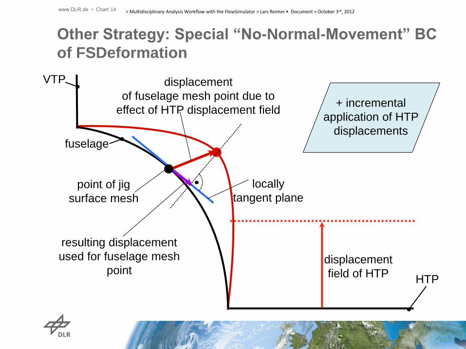
Other Strategy: Special “No-Normal-Movement” BC
of FSDeformation
displacement
field of HTP
point of jig
surface mesh
locally
tangent plane
displacement
of fuselage mesh point due to
effect of HTP displacement field
resulting displacement
used for fuselage mesh
point HTP
fuselage
VTP
+ incremental
application of HTP
displacements
www.DLR.de • Chart 14 > Multidisciplinary Analysis Workflow with the FlowSimulator > Lars Reimer • Document > October 3rd, 2012

HTP rot. angle Y
Z
X
BC 2: Fuselage displ. field computed
internally to compensate for
geo. violation
BC 1: Displacement field for rigidly rotated HTP
Use of FSDeformations’ No-Normal-Movement BC for
Fuselage when Rotating HTPc
www.DLR.de • Chart 15 > Multidisciplinary Analysis Workflow with the FlowSimulator > Lars Reimer • Document > October 3rd, 2012

Required Input data: • Boundary marker of HTP • Boundary marker of attached fuselage part • HTP rotation axis (origin, direction) • Initial HTP setting η • Initial α • Target lift, pitch (trimmed state = 0)
FSTrim.ExportToFSDM
FSMeshTools: Compute displacement field representing rigid HTP rot.
FSDeformation.ChainRun
Run TAU
FSTrim.ImportFromFSDM
While trim condition not fulfilled:
Initial TAU run: TAU.ChainRun()
Final TAU run for trimmed state
η, α
x, Δx
def. mesh
FSTrim computes perturbation
Cl, Cmy
Cl, Cmy
FSTrim: evaluation of trim condition
FSTrim.ImportFromFSDM
FSDM
(Rel‘model,
FSMesh)
LO
OP
www.DLR.de • Chart 16 > Multidisciplinary Analysis Workflow with the FlowSimulator > Lars Reimer • Document > October 3rd, 2012
Trim Loop Implemented in FlowSimulator
CL,Ref-0.1
CL,Ref+0.1
CL,Ref-0.2
CL,Ref-0.3
CL,Ref
CL,Ref
CL,Ref+0.1
CL,Ref-0.1
CL,Ref-0.2
CL,Ref-0.3
CL
www.DLR.de • Chart 17 > Multidisciplinary Analysis Workflow with the FlowSimulator > Lars Reimer • Document > October 3rd, 2012
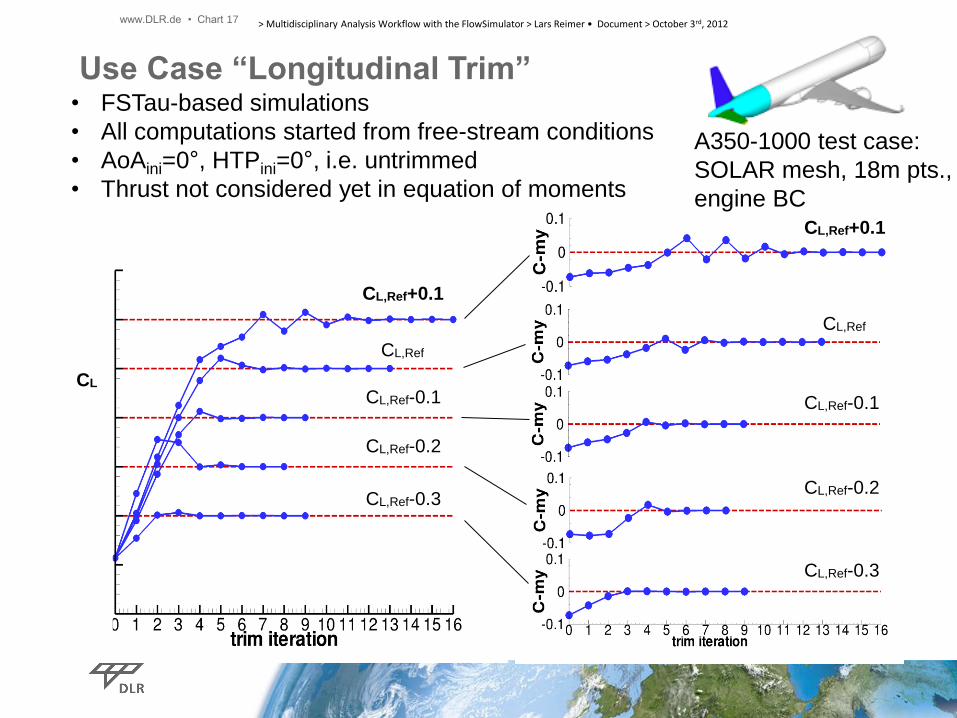
Use Case “Longitudinal Trim”
A350-1000 test case:
SOLAR mesh, 18m pts.,
engine BC
• FSTau-based simulations
• All computations started from free-stream conditions
• AoAini=0°, HTPini=0°, i.e. untrimmed
• Thrust not considered yet in equation of moments

CL,Ref
CL,Ref+0.1
CL,Ref-0.1
CL,Ref-0.2
CL,Ref-0.3
HT
P [
°]
Fuselage shape retained, even for large
HTP rotation angles (+1° to -10°)
Region of
separation
onset at HTP
CL,Ref
CL,Ref+0.1
CL,Ref-0.1
CL,Ref-0.2
CL,Ref-0.3
www.DLR.de • Chart 18 > Multidisciplinary Analysis Workflow with the FlowSimulator > Lars Reimer • Document > October 3rd, 2012
Use Case “Longitudinal Trim”
A350-1000
test case Remark: HTP 0° indicates the initial setting of the HTP in the CFD mesh (which might be non-zero)

~39k FSTAU iter’s
AoA CMy CL
0
A350-1000
test case
Ini. CFD iter‘s. incl.
engine start-up procedure
AoA CMy CL
Dcperturb=0.1
www.DLR.de • Chart 19 > Multidisciplinary Analysis Workflow with the FlowSimulator > Lars Reimer • Document > October 3rd, 2012
Use Case “Longitudinal Trim”
Jacobian computed only
once by forw. difference:
𝐽 =𝑑𝐶𝐿/𝑑𝛼 𝑑𝐶𝑀𝑦/𝑑𝛼𝑑𝐶𝐿/𝑑𝜂 𝑑𝐶𝑀𝑦/𝑑𝜂
• 1 AoA perturbation
• 1 HTP perturbation

We assume that the aircraft is flying a horizontal curve with radius 5000m with
constant turn rate (angular velocity g).
Flow parameters
Ma= 0.5, p = 101325 N / m2 = 1.29 kg / m3, mass: 9295.44 kg
yg
yb
zg
zb
FT,g
g
R
R
VmF
g
gT
2
, =
Use Case “Steady Curve Flight”:
Simpler Config., but more Complex Trim Scenario Involved FS Tools: FSTau + FSTrim + FSDeformation
www.DLR.de • Chart 20 > Multidisciplinary Analysis Workflow with the FlowSimulator > Lars Reimer • Document > October 3rd, 2012

bbbaeroz
bbbaeroy
bbbaerox
gzgaeroz
g
gygaeroy
gxgaerox
qpIIM
prIIM
rqIIM
gmTF
R
VmTF
TF
)(0
)(0
)(0
0
0
0
32,,
13,,
32,,
,,,
2
,,,
,,,
=
=
=
++=
+=
+= zg zb
FT,g
Trim-condition / goal function used
Aerodynamic forces and moments
Thrust
Centrifugal force
Rate of change of angular
momentum
yg
yb
Control parameters :
Roll angle
Pitch angle
Thrust
harileron
hrudder
hHTP
Initial values:
=0°
=5°
=0 N
=0°
=0°
=0°
Gravity
force
Use Case “Steady Curve Flight
www.DLR.de • Chart 21 > Multidisciplinary Analysis Workflow with the FlowSimulator > Lars Reimer • Document > October 3rd, 2012

=> TauPython and FS
trim procedures yield
identical trim results
FS:
TauPython:
V
V
trimmed
flight
state:
Use Case “Steady Curve Flight”:
Comparison with TauPython Tool Chain
www.DLR.de • Chart 22 > Multidisciplinary Analysis Workflow with the FlowSimulator > Lars Reimer • Document > October 3rd, 2012

CFD-CSD Coupled
Simulations with
FlowSimulator
www.DLR.de • Chart 23 > Multidisciplinary Analysis Workflow with the FlowSimulator > Lars Reimer • Document > October 3rd, 2012

FSTau FSCouple CFD -> CSD
FSNatran
Interface
FSCouple CSD -> CFD
FSDeform. …
FSDM
Write
forc
e c
ard
s
Read F
06
Execute
Nastr
an
CFD
mesh
CFD
mesh
+ sol.
CFD
mesh
+sol /
CSD
mesh
CFD+
CSD
coupling
mesh
CSD
coupling
mesh
defo. CSD
coupling
mesh
defo. CSD
coupling
mesh
defo. CFD
coupling
mesh
defo. CFD
coupling
mesh
defo.
CFD
mesh
I/O + system call
on proc. 0
Current work by partners in LuFo
proj. AeroStruct: Integration of
Nastran‘s OpenFSI
interface in FS (enables in-
memory data exchange)
includes Nastran
BDF/F06/OP4/(OP2)
reader & BDF writer
Nastran-based CFD-CSD Coupling with FS
Initial
CFD run
CFD-CSM
LOOP
CONTROL FLOW
FSTau
defo.
CFD
mesh
defo.
CFD
mesh
+ sol.
www.DLR.de • Chart 24 > Multidisciplinary Analysis Workflow with the FlowSimulator > Lars Reimer • Document > October 3rd, 2012
FSTau FSCouple
CFD -> CSD /
CSD -> CFD
FSDeform. …
FSDM
CFD
mesh
CFD
mesh
+ sol.
CFD
mesh
+ sol.
defo. CFD
coupling
mesh
defo. CFD
coupling
mesh
defo.
CFD
mesh
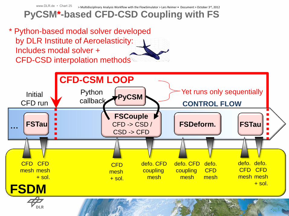
PyCSM*-based CFD-CSD Coupling with FS
PyCSM Yet runs only sequentially
* Python-based modal solver developed
by DLR Institute of Aeroelasticity:
Includes modal solver +
CFD-CSD interpolation methods
Initial
CFD run
CFD-CSM LOOP
CONTROL FLOW
defo.
CFD
mesh
defo.
CFD
mesh
+ sol.
FSTau
Python
callback
www.DLR.de • Chart 25 > Multidisciplinary Analysis Workflow with the FlowSimulator > Lars Reimer • Document > October 3rd, 2012

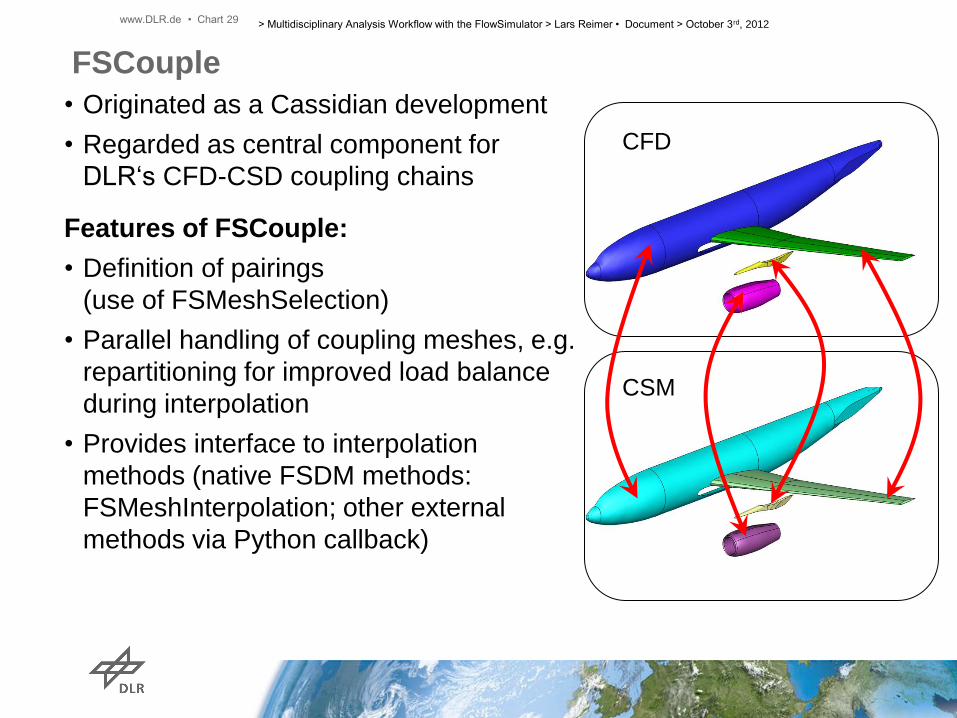
FSCouple
CFD
CSM
• Originated as a Cassidian development
• Regarded as central component for
DLR‘s CFD-CSD coupling chains
Features of FSCouple:
• Definition of pairings
(use of FSMeshSelection)
www.DLR.de • Chart 26 > Multidisciplinary Analysis Workflow with the FlowSimulator > Lars Reimer • Document > October 3rd, 2012

CFD
CSM
FSCouple
• Originated as a Cassidian development
• Regarded as central component for
DLR‘s CFD-CSD coupling chains
Features of FSCouple:
• Definition of pairings
(use of FSMeshSelection)
www.DLR.de • Chart 27 > Multidisciplinary Analysis Workflow with the FlowSimulator > Lars Reimer • Document > October 3rd, 2012

CFD
CSM
FSCouple
• Originated as a Cassidian development
• Regarded as central component for
DLR‘s CFD-CSD coupling chains
Features of FSCouple:
• Definition of pairings
(use of FSMeshSelection)
www.DLR.de • Chart 28 > Multidisciplinary Analysis Workflow with the FlowSimulator > Lars Reimer • Document > October 3rd, 2012
CFD
CSM
FSCouple
• Originated as a Cassidian development
• Regarded as central component for
DLR‘s CFD-CSD coupling chains
Features of FSCouple:
• Definition of pairings
(use of FSMeshSelection)
• Parallel handling of coupling meshes, e.g.
repartitioning for improved load balance
during interpolation
• Provides interface to interpolation
methods (native FSDM methods:
FSMeshInterpolation; other external
methods via Python callback)
www.DLR.de • Chart 29 > Multidisciplinary Analysis Workflow with the FlowSimulator > Lars Reimer • Document > October 3rd, 2012

CFD
CSM
FSCouple
• Originated as a Cassidian development
• Regarded as central component for
DLR‘s CFD-CSD coupling chains
Features of FSCouple:
• Definition of pairings
(use of FSMeshSelection)
• Parallel handling of coupling meshes, e.g.
repartitioning for improved load balance
during interpolation
• Provides interface to interpolation
methods (native FSDM methods:
FSMeshInterpolation; other external
methods via Python callback)
Yet Missing Features:
Inter-pairing blending techniques
(planned to be implemented)
www.DLR.de • Chart 30 > Multidisciplinary Analysis Workflow with the FlowSimulator > Lars Reimer • Document > October 3rd, 2012

www.DLR.de • Chart 31 > Multidisciplinary Analysis Workflow with the FlowSimulator > Lars Reimer • Document > October 3rd, 2012
FSMeshSelection*
• Efficient in parallel mesh
extraction tool
• Applicable to structured &
unstructured meshes
• Allows intuitive boolean
operations
• Mandatory to have for CFD-
CSD coupling
• Nice to have for data reduction
Example Applications
extractíon of the
wing surface
mesh
extraction of a near-wall
block in struct. mesh
data reduction: mesh
slices by intersection
with user-defined
planes
mesh Q/A: transition layer selected via
points belonging to prisms and tetrahedra *part of FSDM (=open source)

www.DLR.de • Chart 32 > Multidisciplinary Analysis Workflow with the FlowSimulator > Lars Reimer • Document > October 3rd, 2012
FSMeshInterpolation*: Interpolation of Pressure Distrib.
So far available meth‘s:
• Volume & surface
mesh interpolation
• Neartest neighbour
interpolation
• Iso-parametric
mapping (FE
shape func.)
Planned:
• RBF-based
(MLS-type)
*part of FSDM (=open source)
CSM
RCB
partitioned
mesh
computed
press. distrib.
interpolated
press. distrib.
PARMETIS
partitioned
mesh
CFD
SOLAR mesh
(quad.-dom.)
39k surf pts.
Shell structure
(quad.-dominant)
2k surf nodes
LANN case, FSTAU, M=0.82, Re=7.3m,
AoA=2.6°, SAO, 1.7m SOLAR mesh, 8 procs

www.DLR.de • Chart 33 > Multidisciplinary Analysis Workflow with the FlowSimulator > Lars Reimer • Document > October 3rd, 2012
*part of FSDM (=open source)
CSM
RCB
partitioned
mesh
computed
press. distrib.
interpolated
press. distrib.
PARMETIS
partitioned
mesh
CFD
SOLAR mesh
(quad.-dom.)
39k surf pts.
Shell structure
(quad.-dominant)
7k surf nodes
FSMeshInterpolation*: Interpolation of Pressure Distrib.
So far available meth‘s:
• Volume & surface
mesh interpolation
• Neartest neighbour
interpolation
• Iso-parametric
mapping (FE
shape func.)
Planned:
• RBF-based
(MLS-type)
LANN case, FSTAU, M=0.82, Re=7.3m,
AoA=2.6°, SAO, 1.7m SOLAR mesh, 8 procs

www.DLR.de • Chart 34 > Multidisciplinary Analysis Workflow with the FlowSimulator > Lars Reimer • Document > October 3rd, 2012
*part of FSDM (=open source)
CSM
RCB
partitioned
mesh
computed
press. distrib.
interpolated
press. distrib.
PARMETIS
partitioned
mesh
CFD
SOLAR mesh
(quad.-dom.)
39k surf pts.
Shell structure
(only tria‘s)
7k surf nodes
FSMeshInterpolation*: Interpolation of Pressure Distrib.
So far available meth‘s:
• Volume & surface
mesh interpolation
• Neartest neighbour
interpolation
• Iso-parametric
mapping (FE
shape func.)
Planned:
• RBF-based
(MLS-type)
LANN case, FSTAU, M=0.82, Re=7.3m,
AoA=2.6°, SAO, 1.7m SOLAR mesh, 8 procs

www.DLR.de • Chart 35 > Multidisciplinary Analysis Workflow with the FlowSimulator > Lars Reimer • Document > October 3rd, 2012
*part of FSDM (=open source)
CSM
RCB
partitioned
mesh
computed
press. distrib.
interpolated
press. distrib.
RCB
partitioned
mesh
CFD
SOLAR mesh
(quad.-dom.)
39k surf pts.
Shell structure
(quad.-dominant)
25k surf nodes
FSMeshInterpolation*: Interpolation of Pressure Distrib.
So far available meth‘s:
• Volume & surface
mesh interpolation
• Neartest neighbour
interpolation
• Iso-parametric
mapping (FE
shape func.)
Planned:
• RBF-based
(MLS-type)
LANN case, FSTAU, M=0.82, Re=7.3m,
AoA=2.6°, SAO, 1.7m SOLAR mesh, 8 procs
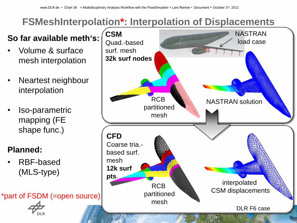
FSMeshInterpolation*: Interpolation of Displacements
www.DLR.de • Chart 36 > Multidisciplinary Analysis Workflow with the FlowSimulator > Lars Reimer • Document > October 3rd, 2012
CFD Coarse tria.-
based surf.
mesh
12k surf
pts.
RCB
partitioned
mesh
RCB
partitioned
mesh
NASTRAN solution
interpolated
CSM displacements
NASTRAN
load case
*part of FSDM (=open source)
So far available meth‘s:
• Volume & surface
mesh interpolation
• Neartest neighbour
interpolation
• Iso-parametric
mapping (FE
shape func.)
Planned:
• RBF-based
(MLS-type)
CSM Quad.-based
surf. mesh
32k surf nodes
DLR F6 case

Use case „F12“: Static Aeroelastic Simulation
www.DLR.de • Chart 37 > Multidisciplinary Analysis Workflow with the FlowSimulator > Lars Reimer • Document > October 3rd, 2012
start of CFD-CSM coupling
20 CSD modes used, PyCSM on proc 0
x/c
cp jig config.
AEC config.
AEC config.
jig config.
M=0.2, Re=1.27m, AoA=8° SAO turb, model
FSTau + FSCouple + PyCSM + FSDeformation
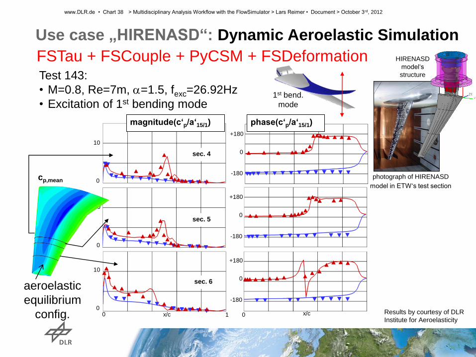
1st bend.
mode
0
+180
-180
phase(c‘p/a‘15/1) magnitude(c‘p/a‘15/1)
x/c x/c 0 1 0
0
+180
-180
0
+180
-180
sec. 6
sec. 4
sec. 5
0
10
0
10
0
10
cp,mean
Results by courtesy of DLR
Institute for Aeroelasticity
Test 143:
• M=0.8, Re=7m, a=1.5, fexc=26.92Hz
• Excitation of 1st bending mode
Use case „HIRENASD“: Dynamic Aeroelastic Simulation
HIRENASD
model‘s
structure
photograph of HIRENASD
model in ETW‘s test section
www.DLR.de • Chart 38 > Multidisciplinary Analysis Workflow with the FlowSimulator > Lars Reimer • Document > October 3rd, 2012
aeroelastic
equilibrium
config.
FSTau + FSCouple + PyCSM + FSDeformation
HTP=4°
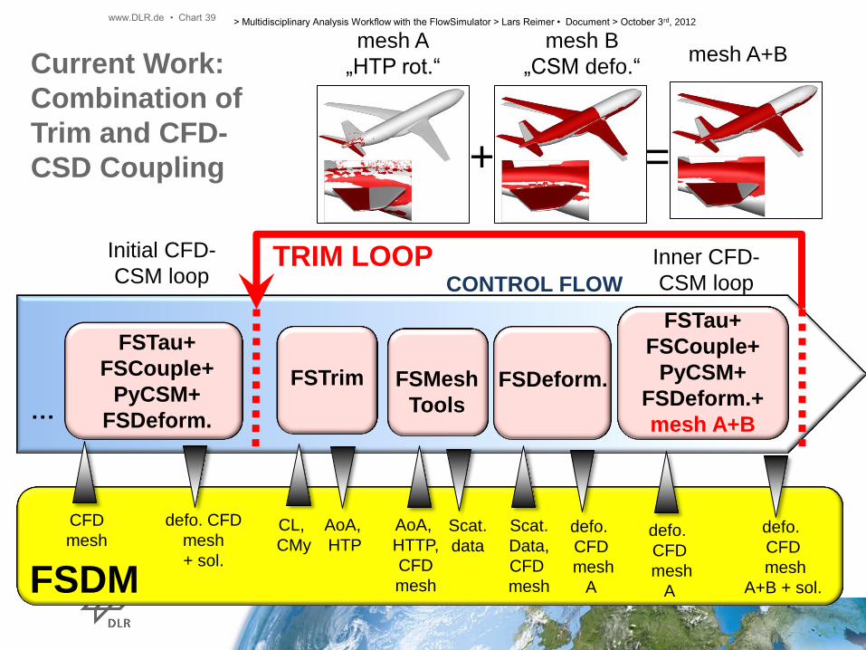
Current Work:
Combination of
Trim and CFD-
CSD Coupling
FSTau+
FSCouple+
PyCSM+
FSDeform. …
Initial CFD-
CSM loop TRIM LOOP
CONTROL FLOW
FSTau+
FSCouple+
PyCSM+
FSDeform.+
mesh A+B
Inner CFD-
CSM loop
FSTrim
FSDM
FSDeform.
defo. CFD
mesh
+ sol.
AoA,
HTP
CL,
CMy
FSMesh
Tools
AoA,
HTTP,
CFD
mesh
Scat.
data
Scat.
Data,
CFD
mesh
defo.
CFD
mesh
A
CFD
mesh defo.
CFD
mesh
A
defo.
CFD
mesh
A+B + sol.
mesh A
„HTP rot.“
mesh B
„CSM defo.“
+ =
mesh A+B
www.DLR.de • Chart 39 > Multidisciplinary Analysis Workflow with the FlowSimulator > Lars Reimer • Document > October 3rd, 2012

Co-processing-based Visualisation
www.DLR.de • Chart 41 > Multidisciplinary Analysis Workflow with the FlowSimulator > Lars Reimer • Document > October 3rd, 2012
Reverse connection
Steering &
Rendering
data transfer
Python layer
simulation
(n processes)
pvserver
(k processes)
Socket-
communication LiveDataSource CoProcessor
ParaView-GUI
Local workstation
HPC cluster Benefits:
• Online monitoring
• Data reduction
• In parallel with sim.
w/o file I/O
• Parallel graphical data proc.
Implementation:
• Based on ParaView
(version 3.9 + small own
modifications)
• Uses ParaView-
CoProcessing lib for
Python-based integration in
simulation
• FS interface available and
applied at Airbus
Co-processing-based Visualisation:
Demonstration
www.DLR.de • Chart 42 > Multidisciplinary Analysis Workflow with the FlowSimulator > Lars Reimer • Document > October 3rd, 2012

Summary
• Potential of FS demonstrated for multidisciplinary
parallel analysis
• DLR strives to use FS for all multidisciplinary
simulations in the near future
• DLR takes over maintenance of FSDeformation
• DLR will further develop FSTrim, FSDeformation,
FSCouple, FSDM and will contribute FS6DoF
• With ongoing FS development more synergy effects of
ONERA and DLR contributions can be expected
www.DLR.de • Chart 43 > Multidisciplinary Analysis Workflow with the FlowSimulator > Lars Reimer • Document > October 3rd, 2012

Examples of Currently Running Projects Involving DLR
with Extense Usage and Development of FlowSImulator
www.DLR.de • Chart 44 > Multidisciplinary Analysis Workflow with the FlowSimulator > Lars Reimer • Document > October 3rd, 2012
• CFD4Loads project (initiated by Airbus)
• DLR project
• German Aerospace Research Programme (LuFo)
project
…

End
www.DLR.de • Chart 45 > Multidisciplinary Analysis Workflow with the FlowSimulator > Lars Reimer • Document > October 3rd, 2012