Embed Size (px)
Citation preview
© MULTIPLEX Modellsport GmbH & Co. KG Westliche Gewerbestr. 1 D-75015 Bretten-Gölshausen GERMANY
Rev.: April 2012
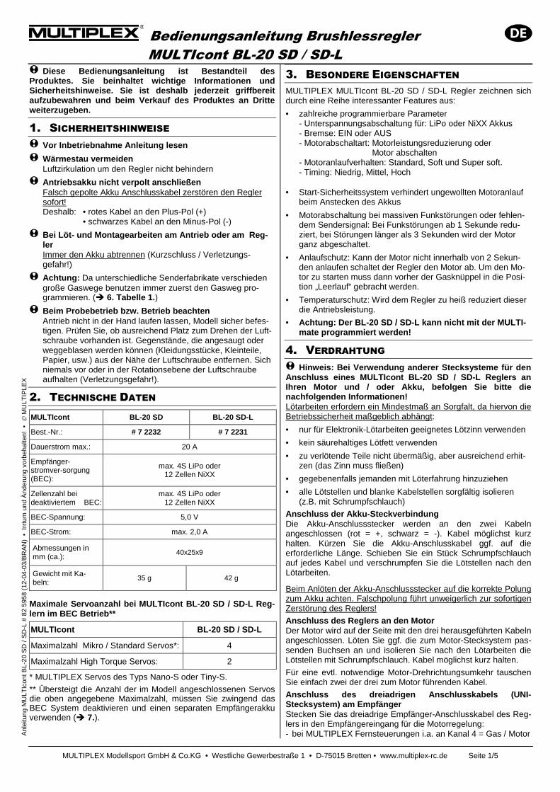
MULTIcont BL-20 SD
Anleitung 2 – 6
Instructions 7 – 11
Instructions 12 – 16
Instrucciones 17 – 21
Istruzioni 22 – 26
Bedienungsanleitung Brushlessregler MULTIcont BL-20 SD / SD-L
MULTIPLEX Modellsport GmbH & Co.KG • Westliche Gewerbestraße 1 • D-75015 Bretten • www.multiplex-rc.de Seite 1/5
A
nlei
tung
MU
LTIc
ont B
L-20
SD
/ S
D-L
# 8
2 59
58 (
12-0
4-03
/BR
AN
) •
Irr
tum
und
Änd
erun
g vo
rbeh
alte
n! •
M
ULT
IPLE
X
! Diese Bedienungsanleitung ist Bestandteil des Produktes. Sie beinhaltet wichtige Informationen und Sicherheitshinweise. Sie ist deshalb jederzeit griffb ereit aufzubewahren und beim Verkauf des Produktes an Drit te weiterzugeben.
1. SICHERHEITSHINWEISE ! Vor Inbetriebnahme Anleitung lesen
! Wärmestau vermeiden Luftzirkulation um den Regler nicht behindern
! Antriebsakku nicht verpolt anschließen Falsch gepolte Akku Anschlusskabel zerstören den Regler sofort!
Deshalb: • rotes Kabel an den Plus-Pol (+) • schwarzes Kabel an den Minus-Pol (-)
! Bei Löt- und Montagearbeiten am Antrieb oder am Re g-ler Immer den Akku abtrennen (Kurzschluss / Verletzungs-gefahr!)
! Achtung: Da unterschiedliche Senderfabrikate verschieden große Gaswege benutzen immer zuerst den Gasweg pro-grammieren. (� 6. Tabelle 1. )
! Beim Probebetrieb bzw. Betrieb beachten Antrieb nicht in der Hand laufen lassen, Modell sicher befes-tigen. Prüfen Sie, ob ausreichend Platz zum Drehen der Luft-schraube vorhanden ist. Gegenstände, die angesaugt oder weggeblasen werden können (Kleidungsstücke, Kleinteile, Papier, usw.) aus der Nähe der Luftschraube entfernen. Sich niemals vor oder in der Rotationsebene der Luftschraube aufhalten (Verletzungsgefahr!).
2. TECHNISCHE DATEN
MULTIcont BL-20 SD BL-20 SD-L
Best.-Nr.: # 7 2232 # 7 2231
Dauerstrom max.: 20 A
Empfänger-stromver-sorgung (BEC):
max. 4S LiPo oder 12 Zellen NiXX
Zellenzahl bei deaktiviertem BEC:
max. 4S LiPo oder 12 Zellen NiXX
BEC-Spannung: 5,0 V
BEC-Strom: max. 2,0 A
Abmessungen in mm (ca.):
40x25x9
Gewicht mit Ka-beln:
35 g 42 g
Maximale Servoanzahl bei MULTIcont BL-20 SD / SD-L Re g-lern im BEC Betrieb**
MULTIcont BL-20 SD / SD-L
Maximalzahl Mikro / Standard Servos*: 4
Maximalzahl High Torque Servos: 2
* MULTIPLEX Servos des Typs Nano-S oder Tiny-S.
** Übersteigt die Anzahl der im Modell angeschlossenen Servos die oben angegebene Maximalzahl, müssen Sie zwingend das BEC System deaktivieren und einen separaten Empfängerakku verwenden (� 7.).
3. BESONDERE EIGENSCHAFTEN MULTIPLEX MULTIcont BL-20 SD / SD-L Regler zeichnen sich durch eine Reihe interessanter Features aus:
• zahlreiche programmierbare Parameter - Unterspannungsabschaltung für: LiPo oder NiXX Akkus - Bremse: EIN oder AUS - Motorabschaltart: Motorleistungsreduzierung oder Motor abschalten - Motoranlaufverhalten: Standard, Soft und Super soft. - Timing: Niedrig, Mittel, Hoch
• Start-Sicherheitssystem verhindert ungewollten Motoranlauf beim Anstecken des Akkus
• Motorabschaltung bei massiven Funkstörungen oder fehlen-dem Sendersignal: Bei Funkstörungen ab 1 Sekunde redu-ziert, bei Störungen länger als 3 Sekunden wird der Motor ganz abgeschaltet.
• Anlaufschutz: Kann der Motor nicht innerhalb von 2 Sekun-den anlaufen schaltet der Regler den Motor ab. Um den Mo-tor zu starten muss dann vorher der Gasknüppel in die Posi-tion „Leerlauf“ gebracht werden.
• Temperaturschutz: Wird dem Regler zu heiß reduziert dieser die Antriebsleistung.
• Achtung: Der BL-20 SD / SD-L kann nicht mit der MULTI -mate programmiert werden!
4. VERDRAHTUNG
! Hinweis: Bei Verwendung anderer Stecksysteme für den Anschluss eines MULTIcont BL-20 SD / SD-L Reglers an Ihren Motor und / oder Akku, befolgen Sie bitte die nachfolgenden Informationen! Lötarbeiten erfordern ein Mindestmaß an Sorgfalt, da hiervon die Betriebssicherheit maßgeblich abhängt:
• nur für Elektronik-Lötarbeiten geeignetes Lötzinn verwenden
• kein säurehaltiges Lötfett verwenden
• zu verlötende Teile nicht übermäßig, aber ausreichend erhit-zen (das Zinn muss fließen)
• gegebenenfalls jemanden mit Löterfahrung hinzuziehen
• alle Lötstellen und blanke Kabelstellen sorgfältig isolieren (z.B. mit Schrumpfschlauch)
Anschluss der Akku-Steckverbindung Die Akku-Anschlussstecker werden an den zwei Kabeln angeschlossen (rot = +, schwarz = -). Kabel möglichst kurz halten. Kürzen Sie die Akku-Anschlusskabel ggf. auf die erforderliche Länge. Schieben Sie ein Stück Schrumpfschlauch auf jedes Kabel und verschrumpfen Sie die Lötstellen nach den Lötarbeiten.
Beim Anlöten der Akku-Anschlussstecker auf die korrekte Polung zum Akku achten. Falschpolung führt unweigerlich zur sofortigen Zerstörung des Reglers!
Anschluss des Reglers an den Motor Der Motor wird auf der Seite mit den drei herausgeführten Kabeln angeschlossen. Löten Sie ggf. die zum Motor-Stecksystem pas-senden Buchsen an und isolieren Sie nach den Lötarbeiten die Lötstellen mit Schrumpfschlauch. Kabel möglichst kurz halten.
Für eine evtl. notwendige Motor-Drehrichtungsumkehr tauschen Sie einfach zwei der drei zum Motor führenden Kabel.
Anschluss des dreiadrigen Anschlusskabels (UNI-Stecksystem) am Empfänger Stecken Sie das dreiadrige Empfänger-Anschlusskabel des Reg-lers in den Empfängereingang für die Motorregelung: - bei MULTIPLEX Fernsteuerungen i.a. an Kanal 4 = Gas / Motor
Bedienungsanleitung Brushlessregler MULTIcont BL-20 SD / SD-L
MULTIPLEX Modellsport GmbH & Co.KG • Westliche Gewerbestraße 1 • D-75015 Bretten • www.multiplex-rc.de Seite 2/5
A
nlei
tung
MU
LTIc
ont B
L-20
SD
/ S
D-L
# 8
2 59
58 (
12-0
4-03
/BR
AN
) •
Irr
tum
und
Änd
erun
g vo
rbeh
alte
n! •
M
ULT
IPLE
X
- bei HiTEC Fernsteuerungen an Kanal 3 = Gas / Motor
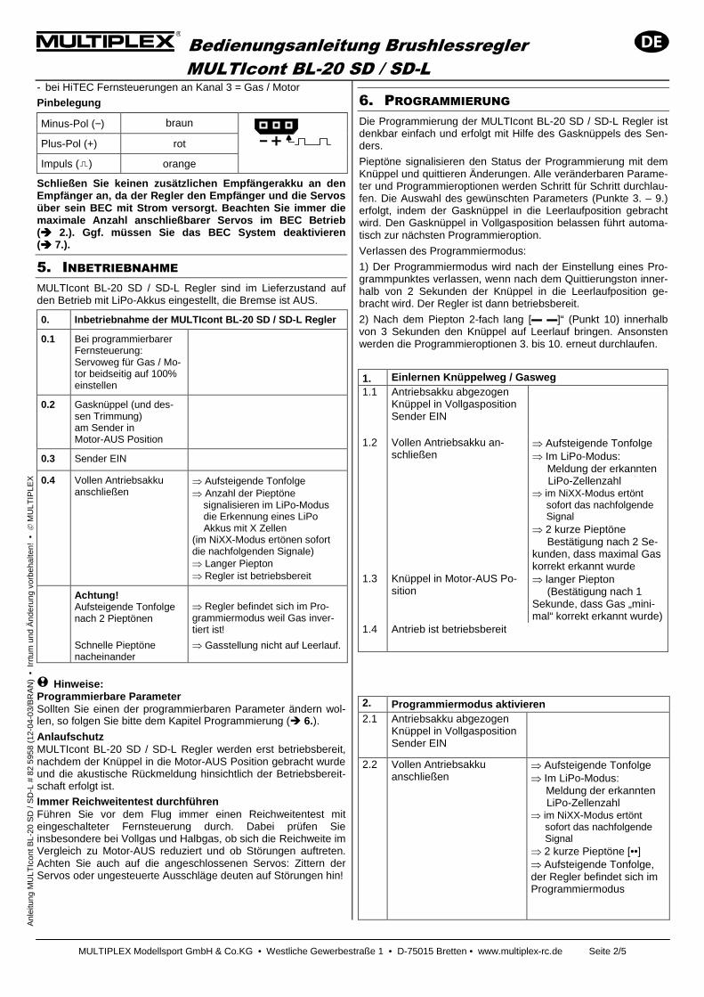
Pinbelegung
Minus-Pol (−) braun
Plus-Pol (+) rot
Impuls ( ) orange
Schließen Sie keinen zusätzlichen Empfängerakku an den Empfänger an, da der Regler den Empfänger und die Serv os über sein BEC mit Strom versorgt. Beachten Sie immer d ie maximale Anzahl anschließbarer Servos im BEC Betrieb (���� 2.). Ggf. müssen Sie das BEC System deaktivieren (���� 7.).
5. INBETRIEBNAHME MULTIcont BL-20 SD / SD-L Regler sind im Lieferzustand auf den Betrieb mit LiPo-Akkus eingestellt, die Bremse ist AUS.
0. Inbetriebnahme der MULTIcont BL-20 SD / SD-L Re gler
0.1 Bei programmierbarer Fernsteuerung: Servoweg für Gas / Mo-tor beidseitig auf 100% einstellen
0.2 Gasknüppel (und des-sen Trimmung) am Sender in Motor-AUS Position
0.3 Sender EIN
0.4 Vollen Antriebsakku anschließen
⇒ Aufsteigende Tonfolge ⇒ Anzahl der Pieptöne signalisieren im LiPo-Modus die Erkennung eines LiPo Akkus mit X Zellen (im NiXX-Modus ertönen sofort die nachfolgenden Signale) ⇒ Langer Piepton ⇒ Regler ist betriebsbereit
Achtung! Aufsteigende Tonfolge nach 2 Pieptönen
Schnelle Pieptöne nacheinander
⇒ Regler befindet sich im Pro-grammiermodus weil Gas inver-tiert ist!
⇒ Gasstellung nicht auf Leerlauf.
! Hinweise: Programmierbare Parameter Sollten Sie einen der programmierbaren Parameter ändern wol-len, so folgen Sie bitte dem Kapitel Programmierung (� 6.). Anlaufschutz MULTIcont BL-20 SD / SD-L Regler werden erst betriebsbereit, nachdem der Knüppel in die Motor-AUS Position gebracht wurde und die akustische Rückmeldung hinsichtlich der Betriebsbereit-schaft erfolgt ist.
Immer Reichweitentest durchführen Führen Sie vor dem Flug immer einen Reichweitentest mit eingeschalteter Fernsteuerung durch. Dabei prüfen Sie insbesondere bei Vollgas und Halbgas, ob sich die Reichweite im Vergleich zu Motor-AUS reduziert und ob Störungen auftreten. Achten Sie auch auf die angeschlossenen Servos: Zittern der Servos oder ungesteuerte Ausschläge deuten auf Störungen hin!
6. PROGRAMMIERUNG Die Programmierung der MULTIcont BL-20 SD / SD-L Regler ist denkbar einfach und erfolgt mit Hilfe des Gasknüppels des Sen-ders.
Pieptöne signalisieren den Status der Programmierung mit dem Knüppel und quittieren Änderungen. Alle veränderbaren Parame-ter und Programmieroptionen werden Schritt für Schritt durchlau-fen. Die Auswahl des gewünschten Parameters (Punkte 3. – 9.) erfolgt, indem der Gasknüppel in die Leerlaufposition gebracht wird. Den Gasknüppel in Vollgasposition belassen führt automa-tisch zur nächsten Programmieroption.
Verlassen des Programmiermodus:
1) Der Programmiermodus wird nach der Einstellung eines Pro-grammpunktes verlassen, wenn nach dem Quittierungston inner-halb von 2 Sekunden der Knüppel in die Leerlaufposition ge-bracht wird. Der Regler ist dann betriebsbereit.
2) Nach dem Piepton 2-fach lang [▬ ▬]“ (Punkt 10) innerhalb von 3 Sekunden den Knüppel auf Leerlauf bringen. Ansonsten werden die Programmieroptionen 3. bis 10. erneut durchlaufen.
1. Einlernen Knüppelweg / Gasweg 1.1 Antriebsakku abgezogen
Knüppel in Vollgasposition Sender EIN
1.2 Vollen Antriebsakku an-schließen
⇒ Aufsteigende Tonfolge ⇒ Im LiPo-Modus: Meldung der erkannten LiPo-Zellenzahl ⇒ im NiXX-Modus ertönt sofort das nachfolgende Signal ⇒ 2 kurze Pieptöne Bestätigung nach 2 Se-kunden, dass maximal Gas korrekt erkannt wurde
1.3 Knüppel in Motor-AUS Po-sition
⇒ langer Piepton (Bestätigung nach 1 Sekunde, dass Gas „mini-mal“ korrekt erkannt wurde)
1.4 Antrieb ist betriebsbereit
2. Programmiermodus aktivieren 2.1 Antriebsakku abgezogen
Knüppel in Vollgasposition Sender EIN
2.2 Vollen Antriebsakku anschließen
⇒ Aufsteigende Tonfolge ⇒ Im LiPo-Modus: Meldung der erkannten LiPo-Zellenzahl ⇒ im NiXX-Modus ertönt sofort das nachfolgende Signal ⇒ 2 kurze Pieptöne [••] ⇒ Aufsteigende Tonfolge, der Regler befindet sich im Programmiermodus
Bedienungsanleitung Brushlessregler MULTIcont BL-20 SD / SD-L
MULTIPLEX Modellsport GmbH & Co.KG • Westliche Gewerbestraße 1 • D-75015 Bretten • www.multiplex-rc.de Seite 3/5
A
nlei
tung
MU
LTIc
ont B
L-20
SD
/ S
D-L
# 8
2 59
58 (
12-0
4-03
/BR
AN
) •
Irr
tum
und
Änd
erun
g vo
rbeh
alte
n! •
M
ULT
IPLE
X
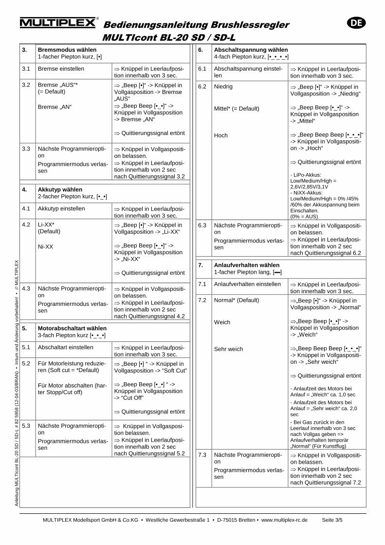
3. Bremsmodus wählen 1-facher Piepton kurz, [•]
3.1 Bremse einstellen ⇒ Knüppel in Leerlaufposi-tion innerhalb von 3 sec.
3.2 Bremse „AUS“* (= Default)
Bremse „AN“
⇒ „Beep [•]“ -> Knüppel in Vollgasposition -> Bremse „AUS“ ⇒ „Beep Beep [•_•]“ -> Knüppel in Vollgasposition -> Bremse „AN“ ⇒ Quittierungssignal ertönt
3.3 Nächste Programmieropti-on
Programmiermodus verlas-sen
⇒ Knüppel in Vollgaspositi-on belassen. ⇒ Knüppel in Leerlaufposi-tion innerhalb von 2 sec nach Quittierungssignal 3.2
4. Akkutyp wählen 2-facher Piepton kurz, [•_•]
4.1 Akkutyp einstellen ⇒ Knüppel in Leerlaufposi-tion innerhalb von 3 sec.
4.2 Li-XX* (Default)
Ni-XX
⇒ „Beep [•]“ -> Knüppel in Vollgasposition -> „Li-XX“ ⇒ „Beep Beep [•_•]“ -> Knüppel in Vollgasposition -> „Ni-XX“ ⇒ Quittierungssignal ertönt
4.3 Nächste Programmieropti-on
Programmiermodus verlas-sen
⇒ Knüppel in Vollgaspositi-on belassen. ⇒ Knüppel in Leerlaufposi-tion innerhalb von 2 sec nach Quittierungssignal 4.2
5. Motorabschaltart wählen 3-fach Piepton kurz [•_•_•]
5.1 Abschaltart einstellen ⇒ Knüppel in Leerlaufposi-tion innerhalb von 3 sec.
5.2 Für Motorleistung reduzie-ren (Soft cut = *Default)
Für Motor abschalten (har-ter Stopp/Cut off)
⇒ „Beep [•] “ -> Knüppel in Vollgasposition -> “Soft Cut” ⇒ „Beep Beep [•_•] “ -> Knüppel in Vollgasposition -> “Cut Off” ⇒ Quittierungssignal ertönt
5.3 Nächste Programmieropti-on
Programmiermodus verlas-sen
⇒ Knüppel in Vollgasposi-tion belassen. ⇒ Knüppel in Leerlaufposi-tion innerhalb von 2 sec nach Quittierungssignal 5.2
6. Abschaltspannung wählen 4-fach Piepton kurz, [•_•_•_•]
6.1 Abschaltspannung einstel-len
⇒ Knüppel in Leerlaufposi-tion innerhalb von 3 sec.
6.2 Niedrig
Mittel* (= Default) Hoch
⇒ „Beep [•]“ -> Knüppel in Vollgasposition -> „Niedrig“ ⇒ „Beep Beep [•_•]“ -> Knüppel in Vollgasposition -> „Mittel“ ⇒ „Beep Beep Beep [•_•_•]“ -> Knüppel in Vollgaspositi-on -> „Hoch“ ⇒ Quittierungssignal ertönt - LiPo-Akkus: Low/Medium/High = 2,6V/2,85V/3,1V - NiXX-Akkus: Low/Medium/High = 0% /45% /60% der Akkuspannung beim Einschalten. (0% = AUS)
6.3 Nächste Programmieropti-on
Programmiermodus verlas-sen
⇒ Knüppel in Vollgaspositi-on belassen. ⇒ Knüppel in Leerlaufposi-tion innerhalb von 2 sec nach Quittierungssignal 6.2
7. Anlaufverhalten wählen 1-facher Piepton lang, [▬]
7.1 Anlaufverhalten einstellen ⇒ Knüppel in Leerlaufposi-tion innerhalb von 3 sec.
7.2 Normal* (Default)
Weich Sehr weich
⇒„Beep [•]“ -> Knüppel in Vollgasposition -> „Normal“ ⇒„Beep Beep [•_•]“ -> Knüppel in Vollgasposition -> „Weich“ ⇒„Beep Beep Beep [•_•_•]“ -> Knüppel in Vollgaspositi-on -> „Sehr weich“ ⇒ Quittierungssignal ertönt - Anlaufzeit des Motors bei Anlauf = „Weich“ ca. 1,0 sec
- Anlaufzeit des Motors bei Anlauf = „Sehr weich“ ca. 2,0 sec
- Bei Gas zurück in den Leerlauf innerhalb von 3 sec nach Vollgas geben => Anlaufverhalten temporär „Normal“ (Für Kunstflug)
7.3 Nächste Programmieropti-on
Programmiermodus verlas-sen
⇒ Knüppel in Vollgaspositi-on belassen. ⇒ Knüppel in Leerlaufposi-tion innerhalb von 2 sec nach Quittierungssignal 7.2
Bedienungsanleitung Brushlessregler MULTIcont BL-20 SD / SD-L
MULTIPLEX Modellsport GmbH & Co.KG • Westliche Gewerbestraße 1 • D-75015 Bretten • www.multiplex-rc.de Seite 4/5
A
nlei
tung
MU
LTIc
ont B
L-20
SD
/ S
D-L
# 8
2 59
58 (
12-0
4-03
/BR
AN
) •
Irr
tum
und
Änd
erun
g vo
rbeh
alte
n! •
M
ULT
IPLE
X
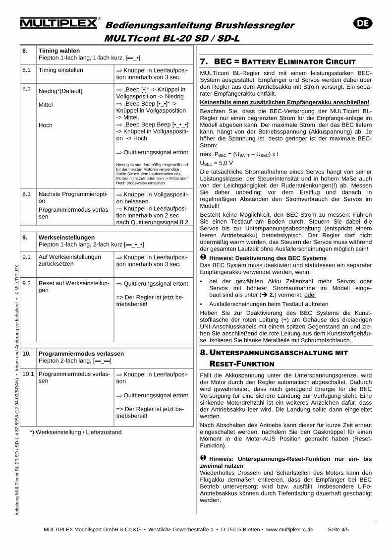
8. Timing wählen Piepton 1-fach lang, 1-fach kurz, [▬_•]
8.1 Timing einstellen ⇒ Knüppel in Leerlaufposi-tion innerhalb von 3 sec.
8.2 Niedrig*(Default) Mittel Hoch
⇒ „Beep [•]“ -> Knüppel in Vollgasposition -> Niedrig ⇒ „Beep Beep [•_•]“ -> Knüppel in Vollgasposition -> Mittel. ⇒ „Beep Beep Beep [•_•_•]“ -> Knüppel in Vollgaspositi-on -> Hoch. ⇒ Quittierungssignal ertönt Niedrig ist standardmäßig eingestellt und für die meisten Motoren verwendbar. Sollte Sie mit dem Laufverhalten des Motors nicht zufrieden sein -> Mittel oder Hoch probeweise einstellen.
8.3 Nächste Programmieropti-on
Programmiermodus verlas-sen
⇒ Knüppel in Vollgaspositi-on belassen. ⇒ Knüppel in Leerlaufposi-tion innerhalb von 2 sec nach Quittierungssignal 8.2
9. Werkseinstellungen Piepton 1-fach lang, 2-fach kurz [▬_•_•]
9.1 Auf Werkseinstellungen zurücksetzen
⇒ Knüppel in Leerlaufposi-tion innerhalb von 3 sec.
9.2 Reset auf Werkseinstellun-gen
⇒ Quittierungssignal ertönt => Der Regler ist jetzt be-triebsbereit!
10. Programmiermodus verlassen Piepton 2-fach lang, [▬_▬]
10.1 Programmiermodus verlas-sen
⇒ Knüppel in Leerlaufposi-tion ⇒ Quittierungssignal ertönt => Der Regler ist jetzt be-triebsbereit!
*) Werkseinstellung / Lieferzustand
7. BEC = BATTERY ELIMINATOR CIRCUIT MULTIcont BL-Regler sind mit einem leistungsstarken BEC-System ausgestattet: Empfänger und Servos werden dabei über den Regler aus dem Antriebsakku mit Strom versorgt. Ein sepa-rater Empfängerakku entfällt.
Keinesfalls einen zusätzlichen Empfängerakku anschli eßen!
Beachten Sie, dass die BEC-Versorgung der MULTIcont BL-Regler nur einen begrenzten Strom für die Empfangs-anlage im Modell abgeben kann. Der maximale Strom, den das BEC liefern kann, hängt von der Betriebsspannung (Akkuspannung) ab. Je höher die Spannung ist, desto geringer ist der maximale BEC-Strom:
max. PBEC = (UBATT – UBEC) x I
UBEC = 5,0 V
Die tatsächliche Stromaufnahme eines Servos hängt von seiner Leistungsklasse, der Steuerintensität und in hohem Maße auch von der Leichtgängigkeit der Ruderanlenkungen(!) ab. Messen Sie daher unbedingt vor dem Erstflug und danach in regelmäßigen Abständen den Stromverbrauch der Servos im Modell!
Besteht keine Möglichkeit, den BEC-Strom zu messen: Führen Sie einen Testlauf am Boden durch. Steuern Sie dabei die Servos bis zur Unterspannungsabschaltung (entspricht einem leeren Antriebsakku) betriebstypisch. Der Regler darf nicht übermäßig warm werden, das Steuern der Servos muss während der gesamten Laufzeit ohne Ausfallerscheinungen möglich sein!
! Hinweis: Deaktivierung des BEC Systems Das BEC System muss deaktiviert und stattdessen ein separater Empfängerakku verwendet werden, wenn:
• bei der gewählten Akku Zellenzahl mehr Servos oder Servos mit höherer Stromaufnahme im Modell einge- baut sind als unter (� 2.) vermerkt, oder
• Ausfallerscheinungen beim Testlauf auftreten
Heben Sie zur Deaktivierung des BEC Systems die Kunst-stofflasche der roten Leitung (+) am Gehäuse des dreiadrigen UNI-Anschlusskabels mit einem spitzen Gegenstand an und zie-hen Sie anschließend die rote Leitung aus dem Kunststoffgehäu-se. Isolieren Sie blanke Metallteile mit Schrumpfschlauch.
8. UNTERSPANNUNGSABSCHALTUNG MIT RESET-FUNKTION
Fällt die Akkuspannung unter die Unterspannungsgrenze, wird der Motor durch den Regler automatisch abgeschaltet. Dadurch wird gewährleistet, dass noch genügend Energie für die BEC Versorgung für eine sichere Landung zur Verfügung steht. Eine sinkende Motordrehzahl ist ein weiteres Anzeichen dafür, dass der Antriebsakku leer wird. Die Landung sollte dann eingeleitet werden.
Nach Abschalten des Antriebs kann dieser für kurze Zeit erneut eingeschaltet werden, nachdem Sie den Gasknüppel für einen Moment in die Motor-AUS Position gebracht haben (Reset-Funktion).
! Hinweis: Unterspannungs-Reset-Funktion nur ein- bi s zweimal nutzen Wiederholtes Drosseln und Scharfstellen des Motors kann den Flugakku dermaßen entleeren, dass der Empfänger bei BEC Betrieb unterversorgt wird bzw. ausfällt. Insbesondere LiPo-Antriebsakkus können durch Tiefentladung dauerhaft geschädigt werden.
Bedienungsanleitung Brushlessregler MULTIcont BL-20 SD / SD-L
MULTIPLEX Modellsport GmbH & Co.KG • Westliche Gewerbestraße 1 • D-75015 Bretten • www.multiplex-rc.de Seite 5/5
A
nlei
tung
MU
LTIc
ont B
L-20
SD
/ S
D-L
# 8
2 59
58 (
12-0
4-03
/BR
AN
) •
Irr
tum
und
Änd
erun
g vo
rbeh
alte
n! •
M
ULT
IPLE
X
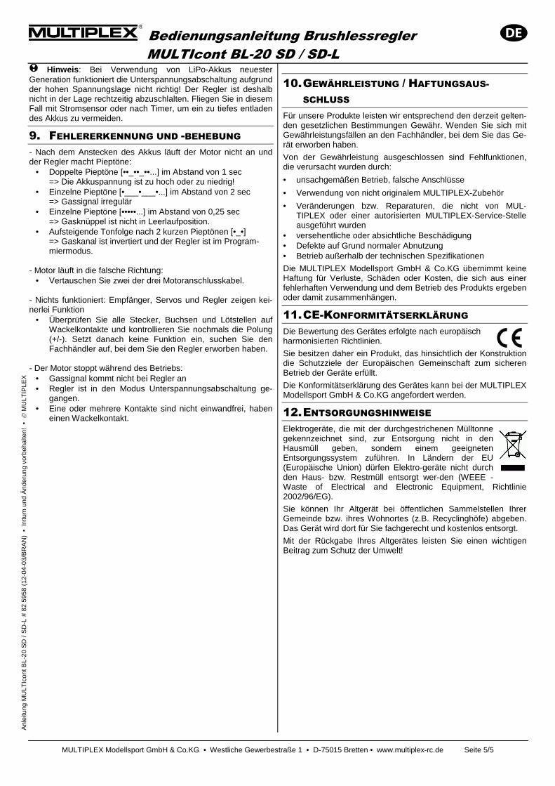
! Hinweis : Bei Verwendung von LiPo-Akkus neuester Generation funktioniert die Unterspannungsabschaltung aufgrund der hohen Spannungslage nicht richtig! Der Regler ist deshalb nicht in der Lage rechtzeitig abzuschlalten. Fliegen Sie in diesem Fall mit Stromsensor oder nach Timer, um ein zu tiefes entladen des Akkus zu vermeiden.
9. FEHLERERKENNUNG UND -BEHEBUNG - Nach dem Anstecken des Akkus läuft der Motor nicht an und der Regler macht Pieptöne:
• Doppelte Pieptöne [••_••_••...] im Abstand von 1 sec => Die Akkuspannung ist zu hoch oder zu niedrig!
• Einzelne Pieptöne [•___•___•...] im Abstand von 2 sec => Gassignal irregulär
• Einzelne Pieptöne [•••••...] im Abstand von 0,25 sec => Gasknüppel ist nicht in Leerlaufposition.
• Aufsteigende Tonfolge nach 2 kurzen Pieptönen [•_•] => Gaskanal ist invertiert und der Regler ist im Program-miermodus.
- Motor läuft in die falsche Richtung:
• Vertauschen Sie zwei der drei Motoranschlusskabel. - Nichts funktioniert: Empfänger, Servos und Regler zeigen kei-nerlei Funktion
• Überprüfen Sie alle Stecker, Buchsen und Lötstellen auf Wackelkontakte und kontrollieren Sie nochmals die Polung (+/-). Setzt danach keine Funktion ein, suchen Sie den Fachhändler auf, bei dem Sie den Regler erworben haben.
- Der Motor stoppt während des Betriebs:
• Gassignal kommt nicht bei Regler an • Regler ist in den Modus Unterspannungsabschaltung ge-
gangen. • Eine oder mehrere Kontakte sind nicht einwandfrei, haben
einen Wackelkontakt.
10. GEWÄHRLEISTUNG / HAFTUNGSAUS-SCHLUSS
Für unsere Produkte leisten wir entsprechend den derzeit gelten-den gesetzlichen Bestimmungen Gewähr. Wenden Sie sich mit Gewährleistungsfällen an den Fachhändler, bei dem Sie das Ge-rät erworben haben.
Von der Gewährleistung ausgeschlossen sind Fehlfunktionen, die verursacht wurden durch:
• unsachgemäßen Betrieb, falsche Anschlüsse
• Verwendung von nicht originalem MULTIPLEX-Zubehör
• Veränderungen bzw. Reparaturen, die nicht von MUL-TIPLEX oder einer autorisierten MULTIPLEX-Service-Stelle ausgeführt wurden
• versehentliche oder absichtliche Beschädigung • Defekte auf Grund normaler Abnutzung • Betrieb außerhalb der technischen Spezifikationen
Die MULTIPLEX Modellsport GmbH & Co.KG übernimmt keine Haftung für Verluste, Schäden oder Kosten, die sich aus einer fehlerhaften Verwendung und dem Betrieb des Produkts ergeben oder damit zusammenhängen.
11. CE-KONFORMITÄTSERKLÄRUNG Die Bewertung des Gerätes erfolgte nach europäisch harmonisierten Richtlinien.
Sie besitzen daher ein Produkt, das hinsichtlich der Konstruktion die Schutzziele der Europäischen Gemeinschaft zum sicheren Betrieb der Geräte erfüllt.
Die Konformitätserklärung des Gerätes kann bei der MULTIPLEX Modellsport GmbH & Co.KG angefordert werden.
12. ENTSORGUNGSHINWEISE Elektrogeräte, die mit der durchgestrichenen Mülltonne gekennzeichnet sind, zur Entsorgung nicht in den Hausmüll geben, sondern einem geeigneten Entsorgungssystem zuführen. In Ländern der EU (Europäische Union) dürfen Elektro-geräte nicht durch den Haus- bzw. Restmüll entsorgt wer-den (WEEE - Waste of Electrical and Electronic Equipment, Richtlinie 2002/96/EG).
Sie können Ihr Altgerät bei öffentlichen Sammelstellen Ihrer Gemeinde bzw. ihres Wohnortes (z.B. Recyclinghöfe) abgeben. Das Gerät wird dort für Sie fachgerecht und kostenlos entsorgt.
Mit der Rückgabe Ihres Altgerätes leisten Sie einen wichtigen Beitrag zum Schutz der Umwelt!
Operating instructions for MULTIcont
BL-20 SD / SD-L brushless speed controllers
MULTIPLEX Modellsport GmbH & Co.KG • Westliche Gewerbestraße 1 • D-75015 Bretten • www.multiplex-rc.de Page 1/5
In
stru
ctio
ns fo
r M
ULT
Icon
t BL-
20 S
D /
SD
-L #
82
5958
(12
-04-
03/B
RA
N)
• E
rror
s an
d om
isss
ions
exc
epte
d. •
M
ULT
IPLE
X
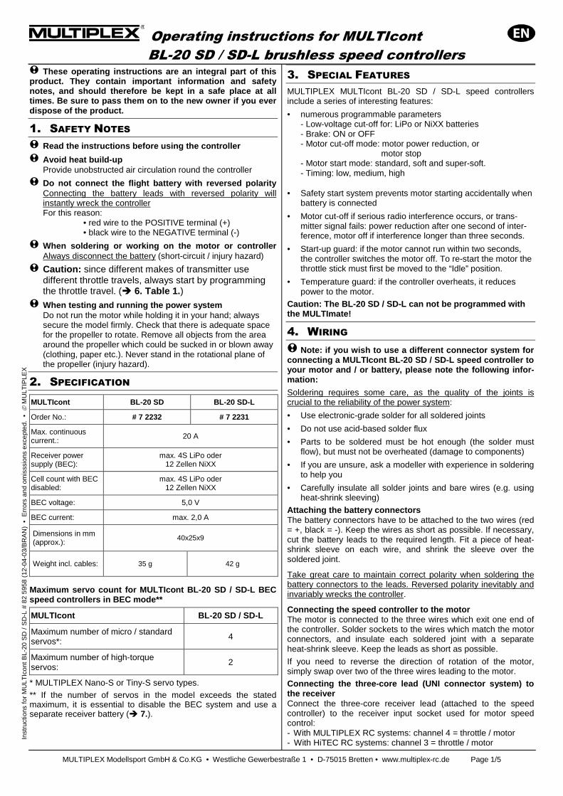
! These operating instructions are an integral part of this product. They contain important information and safety notes, and should therefore be kept in a safe place at all times. Be sure to pass them on to the new owner if you ever dispose of the product.
1. SAFETY NOTES
! Read the instructions before using the controller
! Avoid heat build-up Provide unobstructed air circulation round the controller
! Do not connect the flight battery with reversed polarity Connecting the battery leads with reversed polarity will instantly wreck the controller
For this reason: • red wire to the POSITIVE terminal (+) • black wire to the NEGATIVE terminal (-)
! When soldering or working on the motor or controller Always disconnect the battery (short-circuit / injury hazard)
! Caution: since different makes of transmitter use different throttle travels, always start by programming the throttle travel. (� 6. Table 1.)
! When testing and running the power system Do not run the motor while holding it in your hand; always secure the model firmly. Check that there is adequate space for the propeller to rotate. Remove all objects from the area around the propeller which could be sucked in or blown away (clothing, paper etc.). Never stand in the rotational plane of the propeller (injury hazard).
2. SPECIFICATION
MULTIcont BL-20 SD BL-20 SD-L
Order No.: # 7 2232 # 7 2231
Max. continuous current.:
20 A
Receiver power supply (BEC):
max. 4S LiPo oder 12 Zellen NiXX
Cell count with BEC disabled:
max. 4S LiPo oder 12 Zellen NiXX
BEC voltage: 5,0 V
BEC current: max. 2,0 A
Dimensions in mm (approx.):
40x25x9
Weight incl. cables: 35 g 42 g
Maximum servo count for MULTIcont BL-20 SD / SD-L BEC speed controllers in BEC mode**
MULTIcont BL-20 SD / SD-L
Maximum number of micro / standard servos*: 4
Maximum number of high-torque servos:
2
* MULTIPLEX Nano-S or Tiny-S servo types. ** If the number of servos in the model exceeds the stated maximum, it is essential to disable the BEC system and use a separate receiver battery (� 7.).
3. SPECIAL FEATURES MULTIPLEX MULTIcont BL-20 SD / SD-L speed controllers include a series of interesting features:
• numerous programmable parameters - Low-voltage cut-off for: LiPo or NiXX batteries - Brake: ON or OFF - Motor cut-off mode: motor power reduction, or motor stop - Motor start mode: standard, soft and super-soft. - Timing: low, medium, high
• Safety start system prevents motor starting accidentally when battery is connected
• Motor cut-off if serious radio interference occurs, or trans-mitter signal fails: power reduction after one second of inter-ference, motor off if interference longer than three seconds.
• Start-up guard: if the motor cannot run within two seconds, the controller switches the motor off. To re-start the motor the throttle stick must first be moved to the “Idle” position.
• Temperature guard: if the controller overheats, it reduces power to the motor.
Caution: The BL-20 SD / SD-L can not be programmed with the MULTImate!
4. WIRING
! Note: if you wish to use a different connector system for connecting a MULTIcont BL-20 SD / SD-L speed controller to your motor and / or battery, please note the following infor-mation:
Soldering requires some care, as the quality of the joints is crucial to the reliability of the power system:
• Use electronic-grade solder for all soldered joints
• Do not use acid-based solder flux
• Parts to be soldered must be hot enough (the solder must flow), but must not be overheated (damage to components)
• If you are unsure, ask a modeller with experience in soldering to help you
• Carefully insulate all solder joints and bare wires (e.g. using heat-shrink sleeving)
Attaching the battery connectors The battery connectors have to be attached to the two wires (red = +, black = -). Keep the wires as short as possible. If necessary, cut the battery leads to the required length. Fit a piece of heat-shrink sleeve on each wire, and shrink the sleeve over the soldered joint.
Take great care to maintain correct polarity when soldering the battery connectors to the leads. Reversed polarity inevitably and invariably wrecks the controller.
Connecting the speed controller to the motor The motor is connected to the three wires which exit one end of the controller. Solder sockets to the wires which match the motor connectors, and insulate each soldered joint with a separate heat-shrink sleeve. Keep the leads as short as possible.
If you need to reverse the direction of rotation of the motor, simply swap over two of the three wires leading to the motor.
Connecting the three-core lead (UNI connector system) to the receiver Connect the three-core receiver lead (attached to the speed controller) to the receiver input socket used for motor speed control: - With MULTIPLEX RC systems: channel 4 = throttle / motor - With HiTEC RC systems: channel 3 = throttle / motor
Operating instructions for MULTIcont
BL-20 SD / SD-L brushless speed controllers
MULTIPLEX Modellsport GmbH & Co.KG • Westliche Gewerbestraße 1 • D-75015 Bretten • www.multiplex-rc.de Page 2/5
In
stru
ctio
ns fo
r M
ULT
Icon
t BL-
20 S
D /
SD
-L #
82
5958
(12
-04-
03/B
RA
N)
• E
rror
s an
d om
isss
ions
exc
epte
d. •
M
ULT
IPLE
X
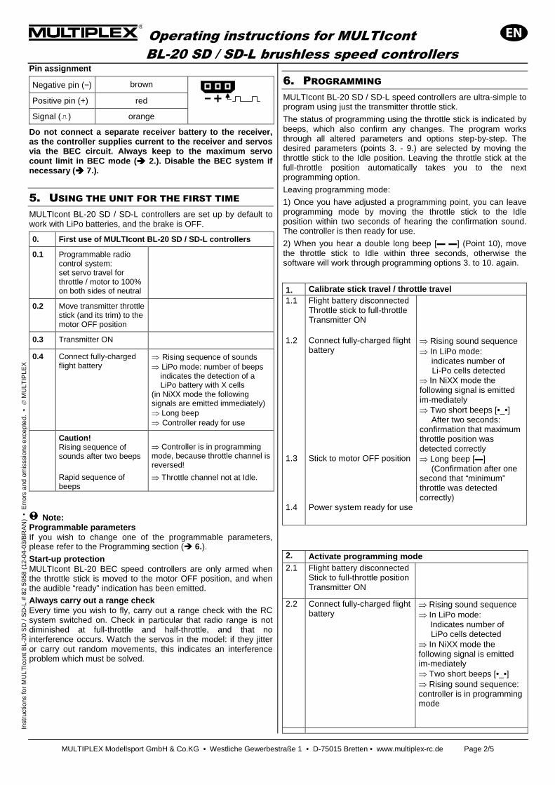
Pin assignment
Negative pin (−) brown
Positive pin (+) red
Signal ( ) orange
Do not connect a separate receiver battery to the receiver, as the controller supplies current to the receiver and servos via the BEC circuit. Always keep to the maximum servo count limit in BEC mode (���� 2.). Disable the BEC system if necessary (���� 7.).
5. USING THE UNIT FOR THE FIRST TIME
MULTIcont BL-20 SD / SD-L controllers are set up by default to work with LiPo batteries, and the brake is OFF.
0. First use of MULTIcont BL-20 SD / SD-L controllers
0.1 Programmable radio control system: set servo travel for throttle / motor to 100% on both sides of neutral
0.2 Move transmitter throttle stick (and its trim) to the motor OFF position
0.3 Transmitter ON
0.4 Connect fully-charged flight battery
⇒ Rising sequence of sounds ⇒ LiPo mode: number of beeps indicates the detection of a LiPo battery with X cells (in NiXX mode the following signals are emitted immediately) ⇒ Long beep ⇒ Controller ready for use
Caution! Rising sequence of sounds after two beeps
Rapid sequence of beeps
⇒ Controller is in programming mode, because throttle channel is reversed!
⇒ Throttle channel not at Idle.
! Note: Programmable parameters If you wish to change one of the programmable parameters, please refer to the Programming section (� 6.). Start-up protection MULTIcont BL-20 BEC speed controllers are only armed when the throttle stick is moved to the motor OFF position, and when the audible “ready” indication has been emitted.
Always carry out a range check Every time you wish to fly, carry out a range check with the RC system switched on. Check in particular that radio range is not diminished at full-throttle and half-throttle, and that no interference occurs. Watch the servos in the model: if they jitter or carry out random movements, this indicates an interference problem which must be solved.
6. PROGRAMMING MULTIcont BL-20 SD / SD-L speed controllers are ultra-simple to program using just the transmitter throttle stick.
The status of programming using the throttle stick is indicated by beeps, which also confirm any changes. The program works through all altered parameters and options step-by-step. The desired parameters (points 3. - 9.) are selected by moving the throttle stick to the Idle position. Leaving the throttle stick at the full-throttle position automatically takes you to the next programming option.
Leaving programming mode:
1) Once you have adjusted a programming point, you can leave programming mode by moving the throttle stick to the Idle position within two seconds of hearing the confirmation sound. The controller is then ready for use.
2) When you hear a double long beep [▬ ▬] (Point 10), move the throttle stick to Idle within three seconds, otherwise the software will work through programming options 3. to 10. again.
1. Calibrate stick travel / throttle travel 1.1 Flight battery disconnected
Throttle stick to full-throttle Transmitter ON
1.2 Connect fully-charged flight battery
⇒ Rising sound sequence ⇒ In LiPo mode: indicates number of Li-Po cells detected ⇒ In NiXX mode the following signal is emitted im-mediately ⇒ Two short beeps [•_•] After two seconds: confirmation that maximum throttle position was detected correctly
1.3 Stick to motor OFF position ⇒ Long beep [▬] (Confirmation after one second that “minimum” throttle was detected correctly)
1.4 Power system ready for use
2. Activate programming mode 2.1 Flight battery disconnected
Stick to full-throttle position Transmitter ON
2.2 Connect fully-charged flight battery
⇒ Rising sound sequence ⇒ In LiPo mode: Indicates number of LiPo cells detected ⇒ In NiXX mode the following signal is emitted im-mediately ⇒ Two short beeps [•_•] ⇒ Rising sound sequence: controller is in programming mode
Operating instructions for MULTIcont
BL-20 SD / SD-L brushless speed controllers
MULTIPLEX Modellsport GmbH & Co.KG • Westliche Gewerbestraße 1 • D-75015 Bretten • www.multiplex-rc.de Page 3/5
In
stru
ctio
ns fo
r M
ULT
Icon
t BL-
20 S
D /
SD
-L #
82
5958
(12
-04-
03/B
RA
N)
• E
rror
s an
d om
isss
ions
exc
epte
d. •
M
ULT
IPLE
X
3. Select brake mode Single short beep [•]
3.1 Set brake ⇒ Stick to Idle position within three seconds
3.2 Brake “OFF”* (= default)
Brake “ON”
⇒ “Beep [•]” -> Stick to full-throttle position -> Brake “OFF” ⇒ “Beep beep [•_•]” -> Stick to full-throttle position -> Brake “ON” ⇒ Confirmation signal emitted
3.3 Next programming option
Leave programming mode
⇒ Leave stick at full-throttle position ⇒ Stick to Idle position within two seconds of hearing confirmation signal 3.2
4. Select battery type Double short beep [•_•]
4.1 Set battery type ⇒ Stick to Idle position within three seconds
4.2 Li-XX* (default)
Ni-XX
⇒ “Beep [•]” -> Stick to full-throttle position -> “Li-XX” ⇒ “Beep beep [•_•]” -> Stick to full-throttle position -> “Ni-XX” ⇒ Confirmation signal emitted
4.3 Next programming option
Leave programming mode
⇒ Leave stick at full-throttle position ⇒ Stick to Idle position within two seconds of hearing confirmation signal 4.2
5. Select motor cut-off type Triple short beep [•_•_•]
5.1 Set cut-off type ⇒ Stick to Idle position within three seconds
5.2 For reduced motor power (soft cut = *default)
For motor cut-off (hard stop / cut-off)
⇒ “Beep [•]” -> Stick to full-throttle position -> “Soft cut” ⇒ “Beep beep [•_•]” -> Stick to full-throttle position -> “Cut-off” ⇒ Confirmation signal emitted
5.3 Next programming option
Leave programming mode
⇒ Leave stick at full-throttle position ⇒ Stick to Idle position within two seconds of con-firmation signal 5.2
6. Select cut-off voltage Quadruple short beep [•_•_•_•]
6.1 Set cut-off voltage ⇒ Stick to Idle position within three seconds
6.2 Low
Medium* (= default) High
⇒ “Beep [•]” -> Stick to full-throttle position -> “Low” ⇒ “Beep beep [•_•]” -> Stick to full-throttle position -> “Medium” ⇒ “Beep beep beep [•_•_•]” -> Stick to full-throttle position -> “High” ⇒ Confirmation signal emitted - LiPo batteries: Low / Medium / High = 2.6 V / 2.85 V / 3.1 V - NiXX batteries: Low / Medium / High = 0% / 45% / 60% of battery voltage when initially switched on. (0% = OFF)
6.3 Next programming option
Leave programming mode
⇒ Leave stick at full-throttle position ⇒ Stick to Idle position within two seconds after hearing confirmation signal 6.2
7. Select Start-up behaviour Single long beep [▬]
7.1 Set motor start behaviour ⇒ Stick to Idle position within three seconds
7.2 Normal* (default)
Soft Very soft
⇒ “Beep [•]” -> Stick to full-throttle position -> “Normal” ⇒ “Beep beep [•_•]” -> Stick to full-throttle position -> “Soft” ⇒ “Beep beep beep [•_•_•]” -> Stick to full-throttle position -> “Very soft” ⇒ Confirmation signal emitted - Motor start-up time = “Soft” approx. 1.0 seconds
- Motor start-up time = “Very soft” approx. 2.0 seconds
- Throttle returned to Idle within three seconds after applying full-throttle => Temporary “Normal” start-up behaviour (for aerobatics)
7.3 Next programming option
Leave programming mode ⇒ Leave stick at full-throttle position ⇒ Stick to Idle position within two seconds after hearing confirmation signal 7.2
Operating instructions for MULTIcont
BL-20 SD / SD-L brushless speed controllers
MULTIPLEX Modellsport GmbH & Co.KG • Westliche Gewerbestraße 1 • D-75015 Bretten • www.multiplex-rc.de Page 4/5
In
stru
ctio
ns fo
r M
ULT
Icon
t BL-
20 S
D /
SD
-L #
82
5958
(12
-04-
03/B
RA
N)
• E
rror
s an
d om
isss
ions
exc
epte
d. •
M
ULT
IPLE
X
8. Select timing One long beep, one short beep [▬_•]
8.1 Set timing ⇒ Stick to Idle position within three seconds
8.2 Low* (default)
Medium
High
⇒ “Beep [•]” -> Stick to full-throttle position -> Low ⇒ “Beep beep [•_•]” -> Stick to full-throttle position -> Medium ⇒ “Beep beep beep [•_•_•]” -> Stick to full-throttle position -> High ⇒ Confirmation signal emitted Low is the default setting, and can be used with most motors. If you are not satisfied with your motor’s running characteristics -> try the Medium or High setting.
8.3 Next programming option
Leave programming mode
⇒ Leave stick at full-throttle position. ⇒ Stick to Idle position within two seconds of hearing confirmation signal 8.2
9. Default settings One long beep, two short beeps [▬_•_•]
9.1 Reset to default settings ⇒ Stick to Idle position within three seconds
9.2 Reset to default settings
⇒ Confirmation signal emitted => Controller ready for use!
10. Leave programming mode Two long beeps [▬_▬]
10.1 Leave programming mode
⇒ Stick to Idle position ⇒ Confirm signal emitted => Controller ready for use!
* Default setting / as supplied
7. BEC = BATTERY ELIMINATOR CIRCUIT MULTIcont BL controllers are equipped with a high-performance BEC system: current is supplied to the receiver and servos from the flight battery via the controller. A separate receiver battery is not required.
Do not connect a separate receiver battery!
Please note that the BEC system of MULTIcont BL controllers can only supply a limited current for the airborne receiving system. The maximum current which the BEC circuit can deliver varies according to the operating voltage (battery voltage). The higher the voltage, the lower the maximum BEC current:
max. PBEC = (UBATT – UBEC) x I
UBEC = 5.0 V
The actual current drawn by a servo varies according to its performance, the frequency of commands and – in parti-cular – the freedom of movement of the control surface linkages(!). This means that it is essential to measure the current drain of the servos in the model before the first flight, and at regular intervals thereafter.
If you have no means of measuring the BEC current: carry out a test-run on the ground: operate the servos in a “normal” way (similar to flying the model) until the low-voltage cut-off is triggered (i.e. battery flat). At this point the speed controller should be no more than warm to the touch, and the servos must work properly all the time, without ever threatening to fail or move erratically.
! Note: disabling the BEC system The BEC system must be disabled, and a separate receiver battery must be used instead, if:
• the model carries more servos, or servos with a higher current drain, than is permissible for the selected battery cell count (� 2.), or
• problems are evident during the test-run, or
• the model is powered by a NiXX flight battery with more than nine cells
Disabling the BEC system: locate the UNI connector attached to the three-core lead. Use a pointed instrument to raise the plastic lug of the red wire (+), and withdraw the red wire from the plastic housing. Insulate the bare metal parts with a heat-shrink sleeve.
8. LOW-VOLTAGE CUT-OFF WITH RESET
FUNCTION
If the battery voltage falls to the low-voltage threshold, the controller automatically cuts off power to the motor. This ensures that sufficient energy is available for the BEC power supply to allow a safe landing to be carried out. A steady decline in motor speed is a further indication that the flight battery is almost discharged; you should initiate the landing as soon as you become aware of this.
If the controller cuts the motor, it can be switched on again briefly if required by momentarily moving the throttle stick to the motor OFF position (Reset function).
! Note: do not use the low-voltage reset function more than once or twice Repeated throttling back to re-arm the motor may dis-charge the flight battery to the point where the receiver power supply falters and fails. Note that LiPo flight batteries can be permanently damaged if they are deep-discharged.
! Note: if you are using the latest generation of LiPo batteries, the low voltage cut-off function will not work correctly due to the
Operating instructions for MULTIcont
BL-20 SD / SD-L brushless speed controllers
MULTIPLEX Modellsport GmbH & Co.KG • Westliche Gewerbestraße 1 • D-75015 Bretten • www.multiplex-rc.de Page 5/5
In
stru
ctio
ns fo
r M
ULT
Icon
t BL-
20 S
D /
SD
-L #
82
5958
(12
-04-
03/B
RA
N)
• E
rror
s an
d om
isss
ions
exc
epte
d. •
M
ULT
IPLE
X
cells’ constantly high voltage curve; in this case the speed controller is unable to cut the motor in good time. In these circumstances you should fly using a current sensor or a timer, to avoid discharging the drive battery to a dangerous level.
9. FINDING AND CORRECTING FAULTS - When you connect the battery, the motor does not start, and the speed controller beeps:
• Double beeps [••_••_••...] at one-second intervals => the battery voltage is too high or too low
• Single beeps [•___•___•...] at two-second intervals => non-standard throttle signal
• Single beeps [•••••...] at 0.25 second intervals => throttle stick is not at Idle position
• Rising sequence of sounds after two short beeps [•_•] => throttle channel is reversed; controller is in programming mode.
- Motor rotates in the wrong direction:
• Interchange any two of the three motor wires. - Nothing works: receiver, servos and speed controller do not respond in any way
• Check all plugs, sockets and soldered joints for poor or intermittent contact, and check polarity (+/-) once more. If the system still does not work, ask for advice from the dealer who sold you the speed controller.
- The motor stops when running:
• Throttle signal not reaching the controller • Controller has entered low-voltage cut-off mode • One or more connectors not making contact, or only making
intermittent contact.
10. GUARANTEE / LIABILITY EXCLUSION
Our products are covered by the currently valid statutory guarantee regulations. If you wish to make a claim under guarantee, please contact the model shop where you originally purchased the unit.
The guarantee does not cover faults caused by:
• Incorrect handling, incorrect connections, reversed po-larity
• The use of accessories other than original MULTIPLEX items
• Modifications or repairs not carried out by MULTIPLEX or by an authorised MULTIPLEX Service Centre
• Accidental or deliberate damage
• Normal wear and tear
• Use of the unit outside the stated Specification
MULTIPLEX Modellsport GmbH & Co.KG accepts no liability for loss, damage or costs which are caused by the incorrect or incompetent use of the product, or are con-nected with such use in any way.
11. CE CONFORMITY DECLARATION This device has been assessed in accordance with the relevant harmonised European directives.
You are therefore the owner of a product whose design fulfils the protective aims of the European Community relating to the safe operation of equipment.
You are entitled to see the conformity declaration. Please ask MULTIPLEX Modellsport GmbH & Co.KG for a copy.
12. DISPOSAL NOTES
Electrical equipment marked with the cancelled waste bin symbol must not be discarded in the standard household waste; instead it must be taken to a suitable specialist disposal or recycling system.
In the countries of the EU (European Union), electrical equipment must not be discarded via the normal domestic refuse system (WEEE - Waste of Electrical and Electronic Equipment, Directive 2002/96/EG). You can take un-wanted equipment to your nearest local authority waste collection point or recycling centre, where the staff will dis-pose of it correctly and at no cost to yourself.
By returning your unwanted equipment you can make an important contribution to the protection of our shared environment!
Notice d’utilisation du régulateur pour
moteur Brushless MULTIcont BL-20 SD / SD-L
MULTIPLEX Modellsport GmbH & Co.KG • Westliche Gewerbestraße 1 • D-75015 Bretten • www.multiplex-rc.de Page 1/5
N
otic
e d’
utili
satio
n du
MU
LTIc
ont B
L-20
SD
/ S
D-L
# 8
2 59
58 (
12-0
4-03
/BR
AN
) •
sou
s ré
serv
e d’
erre
ur o
u de
mod
ifica
tion
tech
niqu
e! •
M
ULT
IPLE
X
!!!! Ces instructions font partie intégrante du produit. Celle-ci contient des informations importantes ainsi que des consignes de sécurités. Elle doit donc être consulta ble à tous moments et à joindre lors d’une revente à tier ces personnes.
1. CONSIGNES DE SECURITES
! Lire les instructions avant la mise en marche
! Evitez l’accumulation de chaleur Garantissez une bonne circulation d’air autour du régulateur
! Ne pas inverser la polarité de l’accu Une inversion des polarités détruirait instantanément le régulateur
D’où: • fil rouge sur la cosse POSITIVE (+) • fil noir sur la cosse NEGATIVE (-)
! Pour tous travaux de soudures ou d’assemblages au niveau de la propulsion ou du régulateur Toujours débrancher l’accu (Court-circuit / Danger corporel!)
! Attention: Du fait que les émetteurs de différents fabricants utilisent différentes courses pour la fonction gaz, il est vivement conseillé de programmer celle-ci en tout premier. (� 6. Tableau 1. )
! Pendant les essais ou en fonctionnement normal Ne pas tenir le moteur en marche dans la main, bien fixer le modèle. Vérifier si vous avez suffisamment de place pour la rotation de l’hélice. Enlever des environs de l’hélice tous les objets qui seraient sujet à une aspiration (vêtement, petites pièces, papier, etc.). Ne vous tenez jamais devant l’hélice ou au niveau du plan de rotation de celle-ci (dangers corporels!).
2. DONNEES TECHNIQUES
MULTIcont BL-20 SD BL-20 SD-L
Nr. Com.: # 7 2232 # 7 2231
Courant continu max.: 20 A
Alimentation du récepteur (BEC):
max. 4S LiPo oder 12 Zellen NiXX
Nombre d’élément avec BEC désactivé:
max. 4S LiPo oder 12 Zellen NiXX
Tension BEC: 5,0 V
Courant BEC: max. 2,0 A
Dimensions en mm (env.):
40x25x9
Poids avec câbles: 35 g 42 g
Nombre maximal de servos utilisables avec le régula teur MULTIcont BL-20 SD / SD-L BEC et la fonction BEC**
MULTIcont BL-20 SD / SD-L
Nbr. max. de servos Micro / Standard*: 4
Nbr. max. de servos High Torque : 2
* Servos MULTIPLEX du type Nano-S ou Tiny-S. ** Si le nombre de servos connectés au récepteur dans votre modèle dépasse le nombre indiqué dans le tableau ci-dessus, il est nécessaire de désactiver le système BEC et d’utiliser un accu de réception séparé (� 7.).
3. CARACTERISTIQUES PARTICULIERES
Les régulateurs de chez MULTIPLEX MULTIcont BL-20 SD / SD-L se détachent des autres régulateurs grâce à quelques caractéristiques très intéressantes:
• De nombreux paramètres programmables - Arrêt par détection de sous-tension pour les accus: LiPo ou NiXX - Fonction frein: marche ou arrêt - Différent type de coupure moteur: réduction de la puissance ou arrêt du moteur - Comportement du moteur au démarrage: Standard, doux et extra doux. - Timing: bas, moyen, haut
• Le système de sécurité au démarrage empêche un démarrage intempestif du moteur lors du branchement de l’accu.
• Arrêt du moteur suite à de fortes perturbations ou absence de signal de transmission: puissance réduite pour des perturbations jusqu’à 1 seconde, coupure moteur si les perturbations sont plus longues que 3 secondes.
• Protection au démarrage: si le moteur ne peut pas démarrer dans un laps de temps de 2 secondes, le régulateur arrête le moteur. Pour démarrer à nouveau le moteur il faut repasser le manche des gaz en position „ralenti“.
• Protection contre la surchauffe: si le régulateur devait trop chauffer, celui-ci réduit automatiquement la puissance.
Attention: Le SD-20 BL / SD-L ne peut pas être progra mmé avec le MULTImate!
4. CABLAGE
! Remarque: Si vous utilisez d’autres systèmes de fic hes pour le branchement du variateur MULTIcont BL-20 SD / SD-L au moteur et /ou a l’accu, suivez les recommandat ions ci-dessous ! Travaux de soudures demandent un minimum de rigueur. En effet, de celle-ci dépend le bon fonctionnement de l’ensemble, et pour cela il faut:
• N’utiliser que de l’étain utilisé en assemblage de cartes électroniques
• Ne pas utiliser de graisse de soudure à base de produits acides
• Ne pas trop chauffer, mais suffisamment, les parties à souder (l’étain doit fondre)
• Demander conseil ou de l’aide à une personne du métier
• Isolez soigneusement toutes les soudures et les parties dénudées des câbles (par ex.: gaine thermo rétractable)
Mise en place du connecteur pour l’accu Le connecteur pour l’accu est à souder aux deux câbles (rouge = +, noir = -). Veillez raccourcir au mieux leur longueur, si nécessaire coupez les à la bonne longueur. Placez un bout de gaine thermo rétractables sur chaque câble et recouvrez la partie dénudée après avoir soudé.
Veillez à respecter la bonne polarité lors du soudage du connecteur pour l’accu. Une inversion de polarité entraîne la destruction immédiate du régulateur!
Branchement du régulateur au moteur Le moteur se branche par ces trois câbles sortant de côté. Soudez les douilles adaptées au système de connexion du moteur et isolez avec de la gaine thermo rétractable les parties dénudées après avoir effectué la soudure. Raccourcissez au maximum la longueur des câbles.
Notice d’utilisation du régulateur pour
moteur Brushless MULTIcont BL-20 SD / SD-L
MULTIPLEX Modellsport GmbH & Co.KG • Westliche Gewerbestraße 1 • D-75015 Bretten • www.multiplex-rc.de Page 2/5
N
otic
e d’
utili
satio
n du
MU
LTIc
ont B
L-20
SD
/ S
D-L
# 8
2 59
58 (
12-0
4-03
/BR
AN
) •
sou
s ré
serv
e d’
erre
ur o
u de
mod
ifica
tion
tech
niqu
e! •
M
ULT
IPLE
X
S’il est nécessaire d’inverser le sens de rotation de votre moteur, il vous suffit d’inverser deux des trois câbles d’alimentations du moteur.
Branchement du câble de commande trois fils (systèm e UNI) au récepteur Branchez le câble de commande à trois fils du régulateur au récepteur à l’emplacement correspondant à la fonction motrice: - pour les émetteurs MULTIPLEX sur le canal 4 = Gaz / Moteur - pour les émetteurs HiTEC sur le canal 3 = Gaz / Moteur
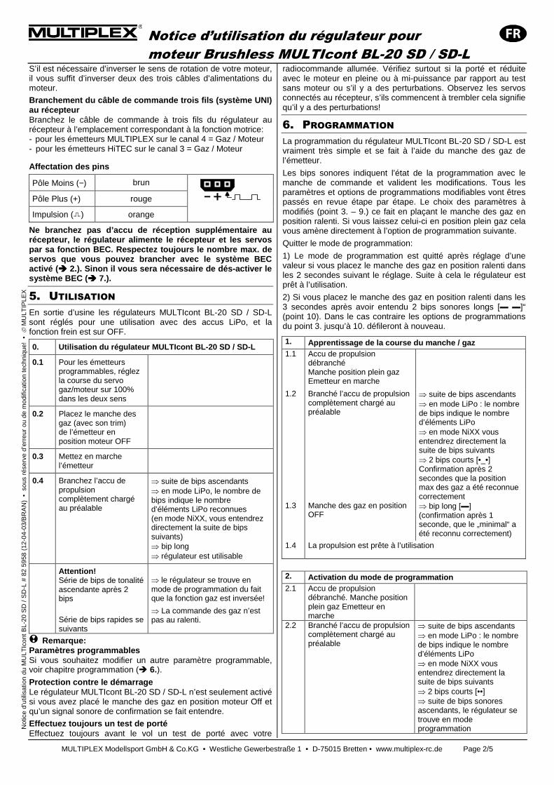
Affectation des pins
Pôle Moins (−) brun
Pôle Plus (+) rouge
Impulsion ( ) orange
Ne branchez pas d’accu de réception supplémentaire au récepteur, le régulateur alimente le récepteur et l es servos par sa fonction BEC. Respectez toujours le nombre ma x. de servos que vous pouvez brancher avec le système BEC activé ( ���� 2.). Sinon il vous sera nécessaire de dés-activer l e système BEC ( ���� 7.).
5. UTILISATION
En sortie d’usine les régulateurs MULTIcont BL-20 SD / SD-L sont réglés pour une utilisation avec des accus LiPo, et la fonction frein est sur OFF.
0. Utilisation du régulateur MULTIcont BL-20 SD / SD-L
0.1 Pour les émetteurs programmables, réglez la course du servo gaz/moteur sur 100% dans les deux sens
0.2 Placez le manche des gaz (avec son trim) de l’émetteur en position moteur OFF
0.3 Mettez en marche l’émetteur
0.4 Branchez l’accu de propulsion complètement chargé au préalable
⇒ suite de bips ascendants ⇒ en mode LiPo, le nombre de bips indique le nombre d’éléments LiPo reconnues (en mode NiXX, vous entendrez directement la suite de bips suivants) ⇒ bip long ⇒ régulateur est utilisable
Attention! Série de bips de tonalité ascendante après 2 bips
Série de bips rapides se suivants
⇒ le régulateur se trouve en mode de programmation du fait que la fonction gaz est inversée!
⇒ La commande des gaz n’est pas au ralenti.
! Remarque: Paramètres programmables Si vous souhaitez modifier un autre paramètre programmable, voir chapitre programmation (� 6.).
Protection contre le démarrage Le régulateur MULTIcont BL-20 SD / SD-L n’est seulement activé si vous avez placé le manche des gaz en position moteur Off et qu’un signal sonore de confirmation se fait entendre.
Effectuez toujours un test de porté Effectuez toujours avant le vol un test de porté avec votre
radiocommande allumée. Vérifiez surtout si la porté et réduite avec le moteur en pleine ou à mi-puissance par rapport au test sans moteur ou s’il y a des perturbations. Observez les servos connectés au récepteur, s’ils commencent à trembler cela signifie qu’il y a des perturbations!
6. PROGRAMMATION
La programmation du régulateur MULTIcont BL-20 SD / SD-L est vraiment très simple et se fait à l’aide du manche des gaz de l’émetteur.
Les bips sonores indiquent l’état de la programmation avec le manche de commande et valident les modifications. Tous les paramètres et options de programmations modifiables vont êtres passés en revue étape par étape. Le choix des paramètres à modifiés (point 3. – 9.) ce fait en plaçant le manche des gaz en position ralenti. Si vous laissez celui-ci en position plein gaz cela vous amène directement à l’option de programmation suivante.
Quitter le mode de programmation:
1) Le mode de programmation est quitté après réglage d’une valeur si vous placez le manche des gaz en position ralenti dans les 2 secondes suivant le réglage. Suite à cela le régulateur est prêt à l’utilisation.
2) Si vous placez le manche des gaz en position ralenti dans les 3 secondes après avoir entendu 2 bips sonores longs [▬ ▬]“ (point 10). Dans le cas contraire les options de programmations du point 3. jusqu’à 10. défileront à nouveau.
1. Apprentissage de la course du manche / gaz 1.1 Accu de propulsion
débranché Manche position plein gaz Emetteur en marche
1.2 Branché l’accu de propulsion complètement chargé au préalable
⇒ suite de bips ascendants ⇒ en mode LiPo : le nombre de bips indique le nombre d’éléments LiPo ⇒ en mode NiXX vous entendrez directement la suite de bips suivants ⇒ 2 bips courts [•_•] Confirmation après 2 secondes que la position max des gaz a été reconnue correctement
1.3 Manche des gaz en position OFF
⇒ bip long [▬] (confirmation après 1 seconde, que le „minimal“ a été reconnu correctement)
1.4 La propulsion est prête à l’utilisation
2. Activation du mode de programmation 2.1 Accu de propulsion
débranché. Manche position plein gaz Emetteur en marche
2.2 Branché l’accu de propulsion complètement chargé au préalable
⇒ suite de bips ascendants ⇒ en mode LiPo : le nombre de bips indique le nombre d’éléments LiPo ⇒ en mode NiXX vous entendrez directement la suite de bips suivants ⇒ 2 bips courts [••] ⇒ suite de bips sonores ascendants, le régulateur se trouve en mode programmation
Notice d’utilisation du régulateur pour
moteur Brushless MULTIcont BL-20 SD / SD-L
MULTIPLEX Modellsport GmbH & Co.KG • Westliche Gewerbestraße 1 • D-75015 Bretten • www.multiplex-rc.de Page 3/5
N
otic
e d’
utili
satio
n du
MU
LTIc
ont B
L-20
SD
/ S
D-L
# 8
2 59
58 (
12-0
4-03
/BR
AN
) •
sou
s ré
serv
e d’
erre
ur o
u de
mod
ifica
tion
tech
niqu
e! •
M
ULT
IPLE
X
3. Choix du mode freinage 1 bip sonore court, [•]
3.1 Réglage du freinage ⇒ Placez le manche en position ralenti dans les 3 secondes.
3.2 Freinage sur „OFF“* (= par défaut)
Freinage sur „ON“
⇒ „Bip [•]“ -> manche en position plein gaz -> freinage „OFF“ ⇒ „Bip Bip [•_•]“ -> manche sur plein gaz -> freinage „ON“ ⇒ Signal sonore de confirmation
3.3 Option de programmation suivante
Quitter le mode de programmation
⇒ Laissez le manche en position plein gaz. ⇒ Mettez le manche en position ralenti dans les 2 sec. Après avoir entendu le signal de confirmation 3.2
4. Choix du type d’accu 2 bips sonores courts, [•_•]
4.1 Réglage du type d’accu ⇒ Placez le manche en position ralenti dans les 3 secondes.
4.2 Li-XX*(Défaut)
Ni-XX
⇒ „Bip [•]“ -> manche en position plein gaz -> „Li-XX“ ⇒ „Bip Bip [•_•]“ -> manche sur plein gaz -> „Ni-XX“ ⇒ Signal sonore de confirmation
4.3 Option de programmation suivante
Quitter le mode de programmation
⇒ Laissez le manche en position plein gaz. ⇒ Mettez le manche en position ralenti dans les 2 sec. Après avoir entendu le signal de confirmation 4.2
5. Choix d’arrêt du moteur 3 bips sonores courts [•_•_•]
5.1 Réglage du choix de type d’arrêt
⇒ Placez le manche en position ralenti dans les 3 secondes.
5.2 Pour une réduction de la puissance moteur (arrêt doux/Soft Cut = *Défaut)
Pour l’arrêt du moteur (arrêt brutal/Cut off)
⇒ „Bip [•]“ -> manche en position plein gaz -> “Soft Cut” ⇒ „Bip Bip [•_•]“ -> manche sur plein gaz -> “Cut Off” ⇒ Signal sonore de confirmation
5.3 Option de programmation suivante
Quitter le mode de programmation
⇒ Laissez le manche en position plein gaz. ⇒ Mettez le manche en position ralenti dans les 2 sec. Après avoir entendu le signal de confirmation 5.2
6. Choix du seuil de tension de coupure 4 bips sonores courts, [•_•_•_•]
6.1 Réglage du seuil d’arrêt ⇒ Placez le manche en position ralenti dans les 3 secondes.
6.2 Bas
Moyen* (= Défaut) Haut
⇒ „Bip [•]“ -> manche en position plein gaz -> „Bas“ ⇒ „Bip Bip [•_•]“ -> manche sur plein gaz -> „Moyen“ ⇒ „ Bip Bip Bip [•_•_•]“ -> manche sur plein gaz -> „Haut“ ⇒ Signal sonore de confirmation - Accus LiPo: Bas/Moyen/Haut = 2,6V/2,85V/3,1V - Accus NiXX: Bas/Moyen/Haut = 0% /45% /60% de la tension nominale de l’accu lors de la mise en marche. (0% = OFF)
6.3 Option de programmation suivante
Quitter le mode de programmation
⇒ Laissez le manche en position plein gaz. ⇒ Mettez le manche en position ralenti dans les 2 sec. Après avoir entendu le signal de confirmation 6.2
7. Choix du comportement au démarrage 1 bip sonore long, [▬]
7.1 Réglage du comportement au démarrage
⇒ Placez le manche en position ralenti dans les 3 secondes.
7.2 Normal* (Défaut) Doux Extra doux
⇒ „Bip [•]“ -> manche en position plein gaz -> „Normal“ ⇒ „Bip Bip [•_•]“ -> manche sur plein gaz -> „Doux“ „ Bip Bip Bip [•_•_•]“ -> manche sur plein gaz -> „Extra doux“ ⇒ Signal sonore de confirmation - Temps de démarrage du moteur pour l’option = „Doux“ env. 1,0 seconde
- Temps de démarrage du moteur pour l’option = „Très doux“ env. 2,0 secondes
- Si vous placez le manche des gaz en position ralenti dans les 3 secondes après avoir mis sur plein gaz => comportement au démarrage temporairement „Normal“ (pour acrobatie)
7.3 Option de programmation suivante
Quitter le mode de programmation
⇒ Laissez le manche en position plein gaz.
⇒ Mettez le manche en position ralenti dans les 2 sec. Après avoir entendu le signal de confirmation 7.2
Notice d’utilisation du régulateur pour
moteur Brushless MULTIcont BL-20 SD / SD-L
MULTIPLEX Modellsport GmbH & Co.KG • Westliche Gewerbestraße 1 • D-75015 Bretten • www.multiplex-rc.de Page 4/5
N
otic
e d’
utili
satio
n du
MU
LTIc
ont B
L-20
SD
/ S
D-L
# 8
2 59
58 (
12-0
4-03
/BR
AN
) •
sou
s ré
serv
e d’
erre
ur o
u de
mod
ifica
tion
tech
niqu
e! •
M
ULT
IPLE
X
8. Choix du Timing Bip sonore 1x long, 1x court [▬_•]
8.1 Réglage du Timing ⇒ placez le manche en position ralenti dans les 3 secondes.
8.2 Bas*(par défaut)
Moyen Haut
⇒ „Bip [•]“ -> placez le manche en position plein gaz -> Bas ⇒ „Bip Bip [•_•]“ -> placez le manche en position plein gaz -> Moyen. ⇒ „Bip Bip Bip [•_•_•]“ -> placez le manche en position plein gaz -> Haut. ⇒ signal de confirmation se fait entendre La valeur basse est réglée par défaut et utilisable pour la plus part des moteurs. Si vous ne deviez pas être satisfait du fonctionnement du moteur -> essayez avec les réglages moyen ou haut.
8.3 Prochaine option de programmation
Quitter le mode programmation
⇒ laissez le manche en position plein gaz. ⇒ placez le manche en position ralenti dans les 2 secondes après avoir entendu le signal de confirmation d’après 8.2
9. Réglages en sorite d’usine Bip sonore 1x long, 2x court [▬_•_•]
9.1 Repasser aux réglages en sortie d’usine
⇒ placez le manche en position ralenti dans les 3 secondes.
9.2 Autre manière de repasser aux réglages en sortie d’usine
⇒ signal de confirmation se fait entendre => Le régulateur est utilisable!
10. Quitter le mode de programmation Bip sonore 2x long, [▬_▬]
10.1 Quitter le mode de programmation
⇒ Placez le manche en position ralenti ⇒ Le signal de confirmation se fait entendre => Le régulateur est utilisable!
* ) Réglages en sortie d’usine / Livraison
7. BEC = BATTERY ELIMINATOR CIRCUIT
Les régulateurs MULTIcont BL 20 SD sont équipés d’un système BEC très puissant: le récepteur et les servos sont alimentés par l’accu de propulsion au travers du régu-lateur. Un accu de réception supplémentaire est inutile.
Ne branchez jamais un accu de réception supplémen-t aire!
Remarquez que le système BEC du régulateur MULTIcont BL n’a qu’une puissance limitée pour alimenter le système de réception du modèle. Le courant maximum que le système BEC peut délivrer dépend de la tension d’alimentation (tension d’accu). Plus la tension est élevée et plus le courant max. que peux délivrer le système BEC sera faible:
max. PBEC = (UBATT – UBEC) x I
UBEC = 5,0 V
La consommation réelle d’un servo dépend de sa classe de puissance, de l’intensité des mouvements et de la légèreté de mouvement des gouvernes(!). De ce fait, mesurez la consommation de courant de vos servos du modèle avant le premier vol, puis par intervalles réguliers!
Si vous n’avez pas la possibilité de mesurer le courant BEC: effectuez un essai au sol. Faite bouger tous les servos jusqu’à arrêt automatique par sous-tension (correspond à un accu de propulsion vide). Le régulateur ne doit pas trop chauffer et la commande des servos doit se faire sans signes de problèmes pendant toute la durée de fonctionnement!
! Remarque: désactivation du système BEC Le système BEC doit être désactivé et il faut utiliser un accu de réception séparé si:
• En fonction du nombre d’élément de votre accu le nombre de servos dans votre modèle est trop grand ou si ceux-ci ont une consommation plus grande que écrit sous (� 2.), ou
• Problèmes de fonctionnement en phase de test ou
• L’utilisation d’un accu de propulsion NiXX de plus de 9 éléments
Pour la désactivation du système BEC, retirez le fil rouge (+) du corps du connecteur UNI trois fils en vous aidant d’un outil pointu pour soulever doucement la languette de fixation. Isolez le fil avec de la gaine thermorétractable.
8. ARRET PAR SOUS-TENSION AVEC FONCTION
RESET
Si la tension de l’accu de propulsion passe en dessous du seuil de sécurité, le régulateur coupe automatiquement l’alimentation du moteur. Cela vous assure d’avoir toujours assez de réserve d’énergie pour le système BEC et de vous permettre un atterrissage en toute sécurité. Une chute de la vitesse de rotation est également un signe que votre accu se vide. Ne tardez pas à atterrir.
Si votre propulsion s’arrête, vous avez toujours le moyen de faire redémarrer celle-ci pour un petit moment après avoir mis le manche de gaz en position moteur OFF (fonction Reset).
! Remarque: n’utilisez la fonction arrêt par sous-tension qu’une ou deux fois La réactivation répétée de la propulsion peut tellement décharger la propulsion que le récepteur n’est plus suf-fisamment alimenté par le système BEC et ne fonctionnera plus correctement. De plus les accus de propulsions LiPo peuvent êtres définitivement endommagés.
Notice d’utilisation du régulateur pour
moteur Brushless MULTIcont BL-20 SD / SD-L
MULTIPLEX Modellsport GmbH & Co.KG • Westliche Gewerbestraße 1 • D-75015 Bretten • www.multiplex-rc.de Page 5/5
N
otic
e d’
utili
satio
n du
MU
LTIc
ont B
L-20
SD
/ S
D-L
# 8
2 59
58 (
12-0
4-03
/BR
AN
) •
sou
s ré
serv
e d’
erre
ur o
u de
mod
ifica
tion
tech
niqu
e! •
M
ULT
IPLE
X
! Remarque : si vous utilisez un accu LiPo de nouvelle génération, la fonction d'arrêt par sous-tension ne fonctionne pas correctement du fait du niveau très élevé de la tension constante! En effet, le régulateur n'est pas capable de couper l'alimentation à temps. Dans ce cas il est conceillé d'utilisez un capteur de courant ou de voler en surveillant le temps d'utilisation afin d'éviter une décharge trop importante de votre accu de propulsion.
9. RECONNAISSANCE - RESOLUTION D’ERREUR
- Après le branchement de l’accu le moteur ne démarre pas et le régulateur émet une série de bips sonores:
• Double bip [••_••_••...] espacés d’1 seconde => la tension de l’accu est trop élevée ou trop basse!
• Bip simples [•___•___•...] espacés de 2 secondes => signal des gaz est irrégulier
• Bip simples [•••••...] espacés de 0,25 secondes => le manche des gaz n’est pas en position ralenti.
• Signal sonore ascendants après 2 bref bips sonores [•_•] => le canal des gaz est inversé et le régulateur est en mode programmation.
- Le moteur tourne dans le mauvais sens:
• Intervertissez le branchement de deux des trois fils d’alimentations du moteur.
- Ne fonctionne pas: récepteur, servos et régulateur ne montrent pas de réaction
• Vérifiez toutes les prises et les soudures afin de voir si vous n’avez pas de mauvais contacts et contrôlez la bonne polarité (+/-) de l’ensemble. Si après ces actions cela ne fonctionne toujours pas allez voir votre revendeur chez qui vous avez acheté votre régulateur.
- Le moteur s’arrête brusquement lors de l’utilisation:
• Le signal de commande des gaz n’arrive pas au régulateur • Le régulateur est passé en mode arrêt par sous-tension. • Un ou plusieurs contacts ne sont plus en bon état, cela se
traduit par un défaut de contact.
10. GARANTIE / EXCLUSIONS DE GARANTIE
Nos produits sont garantis suivant les textes de lois en vigueur. Dans le cas ou vous avez des cas de garanties, adressez-vous directement à votre revendeur chez qui vous avez acheté l’appareil.
Néanmoins, cette garantie ne couvre pas les erreurs de manipulations survenues:
• Utilisation non conforme, mauvais branchement
• Utilisation de matériel d’autre origine que MULTIPLEX
• Modifications / réparations, n’ayant pas été effectué par MULTIPLEX ou station service agréée MULTIPLEX
• Détérioration volontaire ou involontaire
• Défectueux suite à une usure normale
• Utilisation en dehors des spécifications techniques La société MULTIPLEX Modellsport GmbH & Co.KG n’est pas responsable de toutes pertes, dommages ou coûts résultant d’une utilisation non conforme de ce matériel ou des conséquences.
11. DECLARATION DE CONFORMITE CE
L’homologation de ce produit ce fait en fonction des directives européennes harmonisées.
De ce fait vous possédez un produit qui, par sa con-struction, respecte la restriction de sécurités européennes en vigueurs concernant l’utilisation sécurisée des appareils électroniques.
Si nécessaire, vous pouvez demander cette déclaration de conformité auprès de la société MULTIPLEX Modellsport GmbH & Co.KG.
12. CONSIGNES DE RECYCLAGES
Il est strictement interdit de jeter les appareils électroniques repérés par une étiquette avec une poubelle barrée dans les ordures ménagères, emmenez les au point de recyclage le plus proche.
Dans les différents pays constituants l’union euro-péenne, il est interdit de jeter les appareils électroniques dans les ordures ménagères ou une poubelle quelconque, mais doivent êtres recyclés selon le principe de la WEEE (WEEE - Waste of Electrical and Electronic Equipment, directives 2002/96/EG). Vous pouvez donc apporter votre appareil aux différents points de collecte de votre commune ou de votre quartier (par ex.: la déchetterie la plus proche). Celui-ci y sera recyclé gratuitement dans les règles.
En rapportant votre vieil appareil vous contribuer active-ment à la préservation de la nature!
Istruzioni per l’uso del regolatore Brushless MULTIcont BL-20 SD / SD-L
MULTIPLEX Modellsport GmbH & Co.KG • Westliche Gewerbestraße 1 • D-75015 Bretten • www.multiplex-rc.de Seite 1/5
Is
truz
ioni
MU
LTIc
ont B
L-20
SD
/ S
D-L
# 8
2 59
58 (
12-0
4-03
/BR
AN
) •
Irr
tum
und
Änd
erun
g vo
rbeh
alte
n! •
M
ULT
IPLE
X
! Queste istruzioni sono parte integrante del prodott o e contengono informazioni importanti. Per questo motiv o è indispensabile conservarle con cura e, in caso di v endita del prodotto, di consegnarle all’acquirente.
1. AVVERTENZE SULLA SICUREZZA
! Prima di mettere in funzione leggere le istruzioni
! Evitare il surriscaldamento Permettere il ricircolo dell’aria attorno al regolatore
! Non collegare il pacco batteria con polarità invert ita Il collegamento con polarità invertita, danneggia imme-diatamente il regolatore!
Per questo motivo: • cavo rosso al polo POSITIVO (+) • cavo nero al polo NEGATIVO (-)
! Se si devono effettuare delle saldature sul motore o regolatore Scollegare sempre il pacco batteria (pericolo di corto-circuito o di ferirsi)!
! Importante: Visto che le diverse marche delle radio utilizzano diverse corse del gas, programmare sempre innanzituttola corsa del gas (� 6. Table 1.*)
! Durante il funzionamento Non tenere il motore in mano; tenere saldamente il modello. Controllare che ci sia spazio a sufficienza per permettere la rotazione dell’elica. Togliere dalla vici-nanza dell’elica tutti gli oggetti che potrebbero volare via o essere risucchiati (vestiti, minuteria, carta, ecc.). In nessun caso stare davanti o ai lati dell’elica in movimento (ci si può ferire!).
2. DATI TECNICI:
MULTIcont BL-20 SD BL-20 SD-L
Codice di ordinazione: # 7 2232 # 7 2231
Corrente continua max.: 20 A
Alimentazione di corrente ricevente (BEC):
max. 4S LiPo o 12 elementi NiXX
Numero di elementi a BEC deattivato:
max. 4S LiPo o 12 elementi NiXX
Tensione BEC: 5,0 V
Corrente BEC: max. 2,0 A
Dimensioni in mm (ca.): 40x25x9
Peso con cavi: 35 g 42 g
Numero massimo di servi con regolatori MULTIcont BL -20 SD / SD-L nella modalità BEC**
MULTIcont BL-20 SD / SD-L
Numero massimo servi Micro / Standard*:
4
Numero massimo servi High Torque: 2
* Servi MULTIPLEX tipo Nano-S o Tiny-S. ** Se il numero di servi installati nel modello dovesse superare il numero massimo consentito riportato sopra, interrompere l’alimentazione BEC e collegare un pacco batteria Rx separato (� 7.).
3. CARATTERISTICHE I regolatori MULTIcont BL-20 SD / SD-L della MULTIPLEX si contraddistinguono per una serie di proprietà particolari:
• numerosi parametri programmabili - arresto motore per sottotensione per: pacchi batteria LiPo o NiXX - Freno: ON o OFF - Tipo di spegnimento motore: riduzione della potenza del motore o spegnere il motore - Comportamento di avvio del motore: standard, soft e super soft. - Timing: basso, medio, alto
• Sistema di sicurezza per l'avvio evita un avvio indesiderato del motore quando si inserisce il pacco batteria
• Spegnimento del motore nel caso di radiodisturbi forti o in caso di mancanza del segnale della radio: nel caso di radiodisturbi a partire da 1 secondo viene ridotto, nel caso di disturbi più lunghi di 3 secondi il motore viene spento del tutto.
• Protezione di avviamento: se il motore non può avviarsi entro 2 secondi il regolatore spegne il motore. Per poter avviare il motore si deve quindi portare prima lo stick del gas in posizione "al minimo“ .
• Protezione dalla temperatura: se il regolatore diventa troppo caldo questa protezione riduce la potenza di azionamento.
Importante: La BL-20 SD / SD-L non può essere programmato con il MULTImate
4. COLLEGAMENTO
! Nota: Informazioni riguardanti la saldatura Per installare certe varianti dei regolatori MULTIcont BL 20 SD / SD-L si devono eventualmente effettuare delle saldature. Lavori di saldatura richiedono un minimo di accuratezza, per garan-tirne un funzionamento sicuro:
• Usare solo stagno adatto per saldatura su elettronica
• Non usare stagno con contenuto d’acido
• Le parti da saldare devono essere scaldate in modo sufficiente, ma non eccessivo (lo stagno deve „scorre-re“)
• Eventualmente farsi aiutare da qualcuno che abbia esperienza nel lavoro di saldatura
• Isolare accuratamente tutti i punti di saldatura ed i cavi privi di isolazione (p.es. con tubo termorestringente)
Saldare i connettori per il pacco batteria Saldare i connettori per il pacco batteria ai due cavi del regolatore (rosso = +, nero = -). Accorciare il più possibile i cavi. Eventualmente accorciare anche i cavi del pacco batteria. Isolare i punti di saldatura con tubo termorestrin-gente. Accertarsi assolutamente che la polarità sia corretta. Il collegamento del pacco batteria con polarità invertita danneggia immediatamente il regolatore!
Collegare il regolatore al motore Collegare il motore ai tre cavi che sporgono lateralmente dal regolatore. Saldare prese adeguate al sistema di connessione del motore e isolare i punti di saldatura con tubo termorestringente. I cavi di collegamento devono essere accorciati il più possibile.
Per invertire il senso di rotazione del motore, scambiare (invertire) due dei tre cavi di collegamento del motore
Collegare il cavo Rx (sistema di connessione UNI) a lla ricevente Collegare il cavo Rx al canale “Gas / Motore” della rice-vente: - con radio MULTIPLEX al canale 4 = Gas / Motore - con radio HiTEC al canale 3 = Gas / Motore
Istruzioni per l’uso del regolatore Brushless MULTIcont BL-20 SD / SD-L
MULTIPLEX Modellsport GmbH & Co.KG • Westliche Gewerbestraße 1 • D-75015 Bretten • www.multiplex-rc.de Seite 2/5
Is
truz
ioni
MU
LTIc
ont B
L-20
SD
/ S
D-L
# 8
2 59
58 (
12-0
4-03
/BR
AN
) •
Irr
tum
und
Änd
erun
g vo
rbeh
alte
n! •
M
ULT
IPLE
X
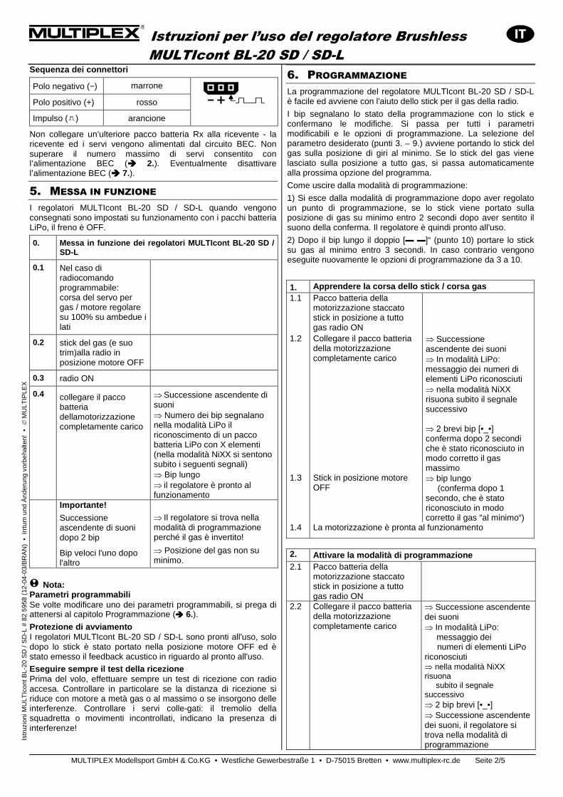
Sequenza dei connettori
Polo negativo (−) marrone
Polo positivo (+) rosso
Impulso ( ) arancione
Non collegare un’ulteriore pacco batteria Rx alla ricevente - la ricevente ed i servi vengono alimentati dal circuito BEC. Non superare il numero massimo di servi consentito con l’alimentazione BEC (���� 2.). Eventualmente disattivare l’alimentazione BEC (���� 7.).
5. MESSA IN FUNZIONE I regolatori MULTIcont BL-20 SD / SD-L quando vengono consegnati sono impostati su funzionamento con i pacchi batteria LiPo, il freno è OFF.
0. Messa in funzione dei regolatori MULTIcont BL-2 0 SD / SD-L
0.1 Nel caso di radiocomando programmabile: corsa del servo per gas / motore regolare su 100% su ambedue i lati
0.2 stick del gas (e suo trim)alla radio in posizione motore OFF
0.3 radio ON
0.4 collegare il pacco batteria dellamotorizzazione completamente carico
⇒ Successione ascendente di suoni ⇒ Numero dei bip segnalano nella modalità LiPo il riconoscimento di un pacco batteria LiPo con X elementi (nella modalità NiXX si sentono subito i seguenti segnali) ⇒ Bip lungo ⇒ il regolatore è pronto al funzionamento
Importante!
Successione ascendente di suoni dopo 2 bip
Bip veloci l'uno dopo l'altro
⇒ Il regolatore si trova nella modalità di programmazione perché il gas è invertito!
⇒ Posizione del gas non su minimo.
! Nota: Parametri programmabili Se volte modificare uno dei parametri programmabili, si prega di attenersi al capitolo Programmazione (���� 6.). Protezione di avviamento I regolatori MULTIcont BL-20 SD / SD-L sono pronti all'uso, solo dopo lo stick è stato portato nella posizione motore OFF ed è stato emesso il feedback acustico in riguardo al pronto all'uso.
Eseguire sempre il test della ricezione Prima del volo, effettuare sempre un test di ricezione con radio accesa. Controllare in particolare se la distanza di ricezione si riduce con motore a metà gas o al massimo o se insorgono delle interferenze. Controllare i servi colle-gati: il tremolio della squadretta o movimenti incontrollati, indicano la presenza di interferenze!
6. PROGRAMMAZIONE La programmazione del regolatore MULTIcont BL-20 SD / SD-L è facile ed avviene con l'aiuto dello stick per il gas della radio.
I bip segnalano lo stato della programmazione con lo stick e confermano le modifiche. Si passa per tutti i parametri modificabili e le opzioni di programmazione. La selezione del parametro desiderato (punti 3. – 9.) avviene portando lo stick del gas sulla posizione di giri al minimo. Se lo stick del gas viene lasciato sulla posizione a tutto gas, si passa automaticamente alla prossima opzione del programma.
Come uscire dalla modalità di programmazione:
1) Si esce dalla modalità di programmazione dopo aver regolato un punto di programmazione, se lo stick viene portato sulla posizione di gas su minimo entro 2 secondi dopo aver sentito il suono della conferma. Il regolatore è quindi pronto all'uso.
2) Dopo il bip lungo il doppio [▬ ▬]“ (punto 10) portare lo stick su gas al minimo entro 3 secondi. In caso contrario vengono eseguite nuovamente le opzioni di programmazione da 3 a 10.
1. Apprendere la corsa dello stick / corsa gas 1.1 Pacco batteria della
motorizzazione staccato stick in posizione a tutto gas radio ON
1.2 Collegare il pacco batteria della motorizzazione completamente carico
⇒ Successione ascendente dei suoni ⇒ In modalità LiPo: messaggio dei numeri di elementi LiPo riconosciuti ⇒ nella modalità NiXX risuona subito il segnale successivo ⇒ 2 brevi bip [•_•] conferma dopo 2 secondi che è stato riconosciuto in modo corretto il gas massimo
1.3 Stick in posizione motore OFF
⇒ bip lungo (conferma dopo 1 secondo, che è stato riconosciuto in modo corretto il gas "al minimo“)
1.4 La motorizzazione è pronta al funzionamento
2. Attivare la modalità di programmazione 2.1 Pacco batteria della
motorizzazione staccato stick in posizione a tutto gas radio ON
2.2 Collegare il pacco batteria della motorizzazione completamente carico
⇒ Successione ascendente dei suoni ⇒ In modalità LiPo: messaggio dei numeri di elementi LiPo riconosciuti ⇒ nella modalità NiXX risuona subito il segnale successivo ⇒ 2 bip brevi [•_•] ⇒ Successione ascendente dei suoni, il regolatore si trova nella modalità di programmazione
Istruzioni per l’uso del regolatore Brushless MULTIcont BL-20 SD / SD-L
MULTIPLEX Modellsport GmbH & Co.KG • Westliche Gewerbestraße 1 • D-75015 Bretten • www.multiplex-rc.de Seite 3/5
Is
truz
ioni
MU
LTIc
ont B
L-20
SD
/ S
D-L
# 8
2 59
58 (
12-0
4-03
/BR
AN
) •
Irr
tum
und
Änd
erun
g vo
rbeh
alte
n! •
M
ULT
IPLE
X
3. Selezionare la modalità freno bip semplice breve, [•]
3.1 Regolare il freno ⇒ Stick in posizione di "al minimo" entro 3 sec.
3.2 Freno "OFF“* (= Default)
Freno "ON“
⇒ „Beep [•]“ -> stick in posizione a tutto gas -> freno "OFF“ ⇒ "Beep Beep [•_•]“ -> stick in posizione a tutto gas -> freno "ON“ ⇒ Risuona il segnale di conferma
3.3 Prossima opzione di programmazione
Uscire dalla modalità di programmazione
⇒ Lasciare lo stick nella posizione a tutto gas. ⇒ Stick in posizione gas al minimo entro 2 sec. dopo il segnale di conferma 3.2
4. Selezionare la modalità pacco batteria bip doppio breve, [•_•]
4.1 Regolare il tipo di pacco batteria
⇒Stick in posizione di "al minimo" entro 3 sec.
4.2 Li-XX* (Default)
Ni-XX
⇒ "Beep [•]“ -> stick in posizione a tutto gas -> "Li-XX“ ⇒ "Beep Beep [•_•]“ -> stick in posizione a tutto gas -> "Ni-XX“ ⇒ Risuona il segnale di conferma
4.3 Prossima opzione di programmazione
Uscire dalla modalità di programmazione
⇒ Lasciare lo stick nella posizione a tutto gas. ⇒ Stick in posizione gas al minimo entro 2 sec. dopo il segnale di conferma 4.2
5. Selezionare tipo di spegnimento motore bip triplo breve [•_•_•]
5.1 Regolare il tipo di spegnimento
⇒Stick in posizione di "al minimo" entro 3 sec.
5.2 Per ridurre la potenza del motore (Soft cut = *Default)
Per spegnere il motore (stop duro/Cut off)
⇒ "Beep [•]“ -> stick in posizione a tutto gas -> "Soft Cut“ ⇒ "Beep Beep [•_•]“ -> stick in posizione a tutto gas -> "Cut Off“ ⇒ Risuona il segnale di conferma
5.3 Prossima opzione di programmazione
Uscire dalla modalità di programmazione
⇒ Lasciare lo stick nella posizione a tutto gas. ⇒ Stick in posizione gas al minimo entro 2 sec. dopo il segnale di conferma 5.2
6. Selezionare la tensione di spegnimento bip quadruplo breve, [•_•_•_•]
6.1 Regolare la tensione di spegnimento
⇒Stick in posizione di "al minimo" entro 3 sec.
6.2 Bassa
Media* (= Default) Alta
⇒ "Beep [•]“ -> stick in posizione a tutto gas -> "Bassa“ ⇒ "Beep Beep [•_•]“ -> stick in posizione a tutto gas -> "Media“ ⇒ "Beep Beep [•_•]“ -> stick in posizione a tutto gas -> "Alta“ ⇒ Risuona il segnale di conferma - Pacco batteria LiPo: Low/Medium/High = 2,6V/2,85V/3,1V - Pacco batteria NiXX: Low/Medium/High = 0% /45% /60% della tensione del pacco batteria durante l'accensione. (0% = OFF)
6.3 Prossima opzione di programmazione
Uscire dalla modalità di programmazione
⇒ Lasciare lo stick nella posizione a tutto gas. ⇒ Stick in posizione gas al minimo entro 2 sec. dopo il segnale di conferma 6.2
7. Selezionare la modalità avviamento bip semplice lungo, [▬]
7.1 Regolare il comportamento di avviamento
⇒Stick in posizione di "al minimo" entro 3 sec.
7.2 Normale* (Default)
Dolce Molto dolce
⇒ "Beep [•]“ -> stick in posizione a tutto gas -> "Normale“ ⇒ "Beep Beep [•_•]“ -> stick in posizione a tutto gas -> "Dolce“ ⇒ "Beep Beep [•_•_•]“ -> stick in posizione a tutto gas -> "Molto dolce“ ⇒ Risuona il segnale di conferma - Tempo di avviamento del motore durante l'avviamento = "dolce“ ca. 1,0 sec
- Tempo di avviamento del motore durante l'avviamento = "molto dolce“ ca. 2,0 sec
- Nel caso di gas indietro al minimo entro 3 sec dopo essere passati a tutto gas => comportamento di avviamento temporaneo "normale“ (per acrobazia)
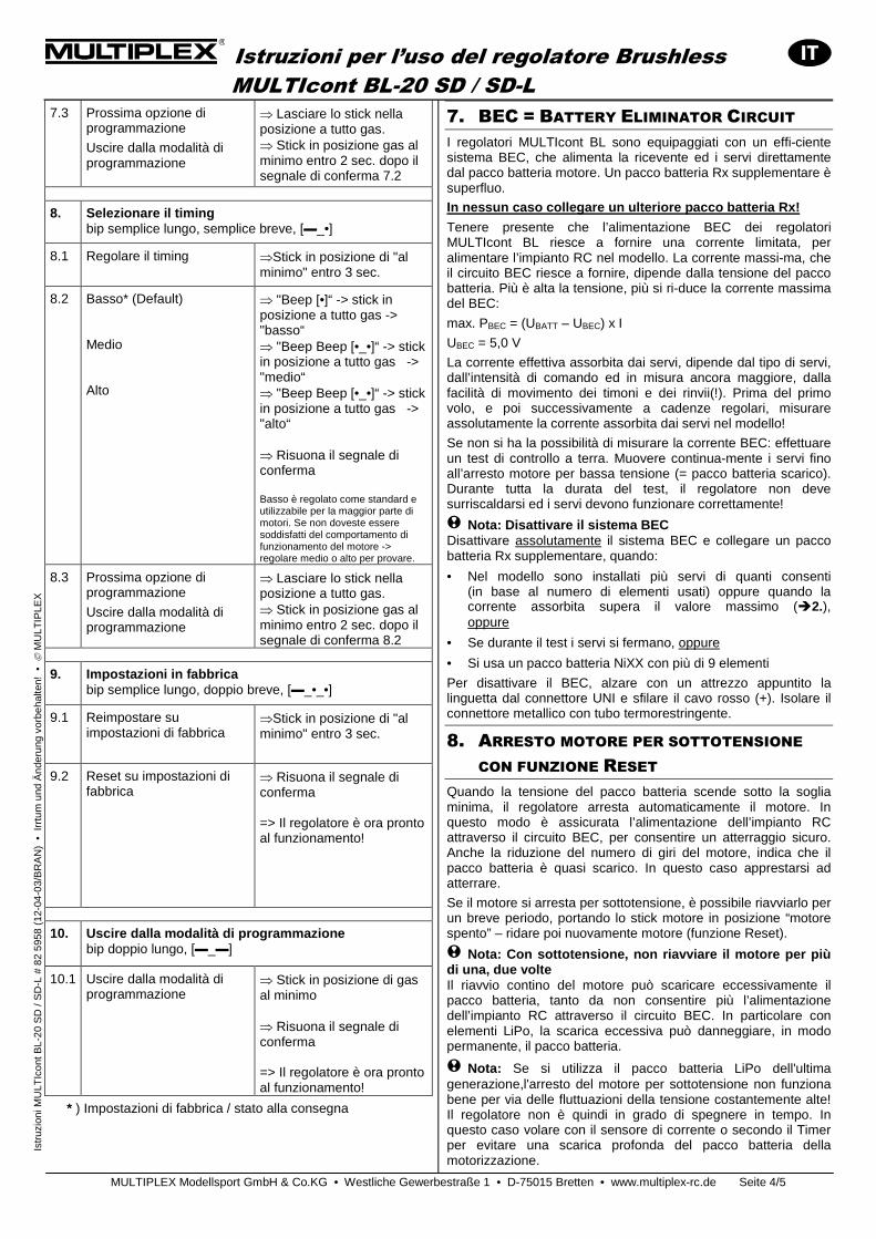
Istruzioni per l’uso del regolatore Brushless MULTIcont BL-20 SD / SD-L
MULTIPLEX Modellsport GmbH & Co.KG • Westliche Gewerbestraße 1 • D-75015 Bretten • www.multiplex-rc.de Seite 4/5
Is
truz
ioni
MU
LTIc
ont B
L-20
SD
/ S
D-L
# 8
2 59
58 (
12-0
4-03
/BR
AN
) •
Irr
tum
und
Änd
erun
g vo
rbeh
alte
n! •
M
ULT
IPLE
X
7.3 Prossima opzione di programmazione
Uscire dalla modalità di programmazione
⇒ Lasciare lo stick nella posizione a tutto gas. ⇒ Stick in posizione gas al minimo entro 2 sec. dopo il segnale di conferma 7.2
8. Selezionare il timing bip semplice lungo, semplice breve, [▬_•]
8.1 Regolare il timing ⇒Stick in posizione di "al minimo" entro 3 sec.
8.2 Basso* (Default) Medio Alto
⇒ "Beep [•]“ -> stick in posizione a tutto gas -> "basso“ ⇒ "Beep Beep [•_•]“ -> stick in posizione a tutto gas -> "medio“ ⇒ "Beep Beep [•_•]“ -> stick in posizione a tutto gas -> "alto“ ⇒ Risuona il segnale di conferma Basso è regolato come standard e utilizzabile per la maggior parte di motori. Se non doveste essere soddisfatti del comportamento di funzionamento del motore -> regolare medio o alto per provare.
8.3 Prossima opzione di programmazione
Uscire dalla modalità di programmazione
⇒ Lasciare lo stick nella posizione a tutto gas. ⇒ Stick in posizione gas al minimo entro 2 sec. dopo il segnale di conferma 8.2
9. Impostazioni in fabbrica bip semplice lungo, doppio breve, [▬_•_•]
9.1 Reimpostare su impostazioni di fabbrica
⇒Stick in posizione di "al minimo" entro 3 sec.
9.2 Reset su impostazioni di fabbrica
⇒ Risuona il segnale di conferma => Il regolatore è ora pronto al funzionamento!
10. Uscire dalla modalità di programmazione bip doppio lungo, [▬_▬]
10.1 Uscire dalla modalità di programmazione
⇒ Stick in posizione di gas al minimo ⇒ Risuona il segnale di conferma => Il regolatore è ora pronto al funzionamento!
* ) Impostazioni di fabbrica / stato alla consegna
7. BEC = BATTERY ELIMINATOR CIRCUIT I regolatori MULTIcont BL sono equipaggiati con un effi-ciente sistema BEC, che alimenta la ricevente ed i servi direttamente dal pacco batteria motore. Un pacco batteria Rx supplementare è superfluo.
In nessun caso collegare un ulteriore pacco batteri a Rx!
Tenere presente che l’alimentazione BEC dei regolatori MULTIcont BL riesce a fornire una corrente limitata, per alimentare l’impianto RC nel modello. La corrente massi-ma, che il circuito BEC riesce a fornire, dipende dalla tensione del pacco batteria. Più è alta la tensione, più si ri-duce la corrente massima del BEC:
max. PBEC = (UBATT – UBEC) x I
UBEC = 5,0 V
La corrente effettiva assorbita dai servi, dipende dal tipo di servi, dall’intensità di comando ed in misura ancora maggiore, dalla facilità di movimento dei timoni e dei rinvii(!). Prima del primo volo, e poi successivamente a cadenze regolari, misurare assolutamente la corrente assorbita dai servi nel modello!
Se non si ha la possibilità di misurare la corrente BEC: effettuare un test di controllo a terra. Muovere continua-mente i servi fino all’arresto motore per bassa tensione (= pacco batteria scarico). Durante tutta la durata del test, il regolatore non deve surriscaldarsi ed i servi devono funzionare correttamente!
! Nota: Disattivare il sistema BEC Disattivare assolutamente il sistema BEC e collegare un pacco batteria Rx supplementare, quando:
• Nel modello sono installati più servi di quanti consenti (in base al numero di elementi usati) oppure quando la corrente assorbita supera il valore massimo (�2.), oppure
• Se durante il test i servi si fermano, oppure
• Si usa un pacco batteria NiXX con più di 9 elementi
Per disattivare il BEC, alzare con un attrezzo appuntito la linguetta dal connettore UNI e sfilare il cavo rosso (+). Isolare il connettore metallico con tubo termorestringente.
8. ARRESTO MOTORE PER SOTTOTENSIONE
CON FUNZIONE RESET Quando la tensione del pacco batteria scende sotto la soglia minima, il regolatore arresta automaticamente il motore. In questo modo è assicurata l’alimentazione dell’impianto RC attraverso il circuito BEC, per consentire un atterraggio sicuro. Anche la riduzione del numero di giri del motore, indica che il pacco batteria è quasi scarico. In questo caso apprestarsi ad atterrare.
Se il motore si arresta per sottotensione, è possibile riavviarlo per un breve periodo, portando lo stick motore in posizione “motore spento” – ridare poi nuovamente motore (funzione Reset).
! Nota: Con sottotensione, non riavviare il motore p er più di una, due volte Il riavvio contino del motore può scaricare eccessivamente il pacco batteria, tanto da non consentire più l’alimentazione dell’impianto RC attraverso il circuito BEC. In particolare con elementi LiPo, la scarica eccessiva può danneggiare, in modo permanente, il pacco batteria.
! Nota: Se si utilizza il pacco batteria LiPo dell'ultima generazione,l'arresto del motore per sottotensione non funziona bene per via delle fluttuazioni della tensione costantemente alte! Il regolatore non è quindi in grado di spegnere in tempo. In questo caso volare con il sensore di corrente o secondo il Timer per evitare una scarica profonda del pacco batteria della motorizzazione.
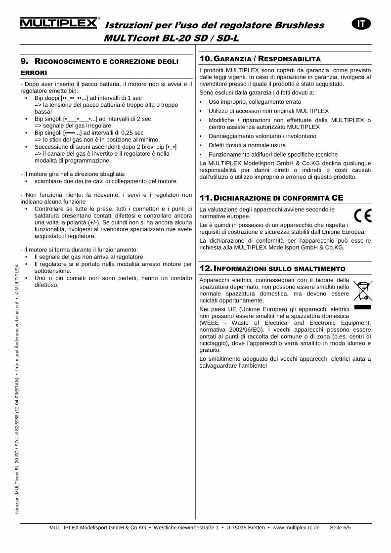
Istruzioni per l’uso del regolatore Brushless MULTIcont BL-20 SD / SD-L
MULTIPLEX Modellsport GmbH & Co.KG • Westliche Gewerbestraße 1 • D-75015 Bretten • www.multiplex-rc.de Seite 5/5
Is
truz
ioni
MU
LTIc
ont B
L-20
SD
/ S
D-L
# 8
2 59
58 (
12-0
4-03
/BR
AN
) •
Irr
tum
und
Änd
erun
g vo
rbeh
alte
n! •
M
ULT
IPLE
X
9. RICONOSCIMENTO E CORREZIONE DEGLI
ERRORI - Dopo aver inserito il pacco batteria, il motore non si avvia e il regolatore emette bip:
• Bip doppi [••_••_••...] ad intervalli di 1 sec => la tensione del pacco batteria è troppo alta o troppo bassa!
• Bip singoli [•___•___•...] ad intervalli di 2 sec => segnale del gas irregolare
• Bip singoli [•••••...] ad intervalli di 0,25 sec => lo stick del gas non è in posizione al minimo.
• Successione di suoni ascendenti dopo 2 brevi bip [•_•] => il canale del gas è invertito e il regolatore è nella modalità di programmazione.
- Il motore gira nella direzione sbagliata:
• scambiare due dei tre cavi di collegamento del motore. - Non funziona niente: la ricevente, i servi e i regolatori non indicano alcuna funzione
• Controllare se tutte le prese, tutti i connettori e i punti di saldatura presentano contatti difettosi e controllare ancora una volta la polarità (+/-). Se quindi non si ha ancora alcuna funzionalità, rivolgersi al rivenditore specializzato ove avete acquistato il regolatore.
- Il motore si ferma durante il funzionamento:
• Il segnale del gas non arriva al regolatore • Il regolatore si è portato nella modalità arresto motore per
sottotensione. • Uno o più contatti non sono perfetti, hanno un contatto
difettoso.
10. GARANZIA / RESPONSABILITÀ I prodotti MULTIPLEX sono coperti da garanzia, come previsto dalle leggi vigenti. In caso di riparazione in garanzia, rivolgersi al rivenditore presso il quale il prodotto è stato acquistato.
Sono esclusi dalla garanzia i difetti dovuti a:
• Uso improprio, collegamento errato
• Utilizzo di accessori non originali MULTIPLEX
• Modifiche / riparazioni non effettuate dalla MULTIPLEX o centro assistenza autorizzato MULTIPLEX
• Danneggiamento volontario / involontario
• Difetti dovuti a normale usura
• Funzionamento aldifuori delle specifiche tecniche
La MULTIPLEX Modellsport GmbH & Co.KG declina qualunque responsabilità per danni diretti o indiretti o costi causati dall’utilizzo o utilizzo improprio o erroneo di questo prodotto.
11. DICHIARAZIONE DI CONFORMITÀ CE La valutazione degli apparecchi avviene secondo le normative europee.
Lei è quindi in possesso di un apparecchio che rispetta i requisiti di costruzione e sicurezza stabiliti dall’Unione Europea.
La dichiarazione di conformità per l’apparecchio può esse-re richiesta alla MULTIPLEX Modellsport GmbH & Co.KG.
12. INFORMAZIONI SULLO SMALTIMENTO Apparecchi elettrici, contrassegnati con il bidone della spazzatura depennato, non possono essere smaltiti nella normale spazzatura domestica, ma devono essere riciclati opportunamente.
Nei paesi UE (Unione Europea) gli apparecchi elettrici non possono essere smaltiti nella spazzatura domestica (WEEE - Waste of Electrical and Electronic Equipment, normativa 2002/96/EG). I vecchi apparecchi possono essere portati ai punti di raccolta del comune o di zona (p.es. centri di riciclaggio), dove l’apparecchio verrà smaltito in modo idoneo e gratuito.
Lo smaltimento adeguato dei vecchi apparecchi elettrici aiuta a salvaguardare l’ambiente!
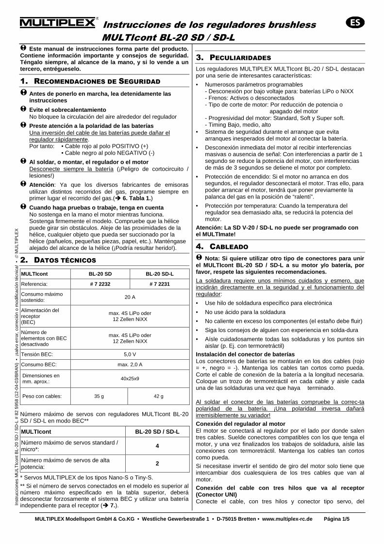
Instrucciones de los reguladores brushless MULTIcont BL-20 SD / SD-L
MULTIPLEX Modellsport GmbH & Co.KG • Westliche Ge werbestraße 1 • D-75015 Bretten • www.multiplex- rc.de Página 1/5
In
stru
ccio
nes
MU
LTIc
ont B
L-20
SD
/ S
D-L
# 8
2 59
58 (
12-0
4-03
/BR
AN
) •
¡sa
lvo
erro
r, c
orre
ción
o m
odifi
caci
ón té
cnic
a! •
M
ULT
IPLE
X
! Este manual de instrucciones forma parte del product o. Contiene información importante y consejos de segur idad. Téngalo siempre, al alcance de la mano, y si lo ven de a un tercero, entrégueselo.
1. RECOMENDACIONES DE SEGURIDAD
! Antes de ponerlo en marcha, lea detenidamente las instrucciones
! Evite el sobrecalentamiento No bloquee la circulación del aire alrededor del regulador
! Preste atención a la polaridad de las baterías Una inversión del cable de las baterías puede dañar el regulador rápidamente. Por tanto: • Cable rojo al polo POSITIVO (+) • Cable negro al polo NEGATIVO (-)
! Al soldar, o montar, el regulador o el motor Desconecte siempre la batería (¡Peligro de cortocircuito / lesiones!)
! Atención : Ya que los diversos fabricantes de emisoras utilizan distintos recorridos del gas, programe siempre en primer lugar el recorrido del gas.(� 6. Tabla 1. )
! Cuando haga pruebas o trabaje, tenga en cuenta No sostenga en la mano el motor mientras funciona. Sostenga firmemente el modelo. Compruebe que la hélice puede girar sin obstáculos. Aleje de las proximidades de la hélice, cualquier objeto que pueda ser succionado por la hélice (pañuelos, pequeñas piezas, papel, etc.). Manténgase alejado del alcance de la hélice (¡Podría resultar herido!).
2. DATOS TÉCNICOS
MULTIcont BL-20 SD BL-20 SD-L
Referencia: # 7 2232 # 7 2231
Consumo máximo sostenido:
20 A
Alimentación del receptor (BEC)
max. 4S LiPo oder 12 Zellen NiXX
Número de elementos con BEC desactivado
max. 4S LiPo oder 12 Zellen NiXX
Tensión BEC: 5,0 V
Consumo BEC: max. 2,0 A
Dimensiones en mm. aprox.: 40x25x9
Peso con cables: 35 g 42 g
Número máximo de servos con reguladores MULTIcont BL-20 SD / SD-L en modo BEC**
MULTIcont BL-20 SD / SD-L
Número máximo de servos standard / micro*: 4
Número máximo de servos de alta potencia: 2
* Servos MULTIPLEX de los tipos Nano-S o Tiny-S.
** Si el número de servos conectados en el modelo es superior al número máximo especificado en la tabla superior, deberá desconectar forzosamente el sistema BEC y utilizar una batería independiente para el receptor (� 7.).
3. PECULIARIDADES Los reguladores MULTIPLEX MULTIcont BL-20 / SD-L destacan por una serie de interesantes características:
• Numerosos parámetros programables - Desconexión por bajo voltaje para: baterías LiPo o NiXX - Frenos: Activos o desconectados - Tipo de corte de motor: Por reducción de potencia o apagado del motor - Progresividad del motor: Standard, Soft y Super soft. - Timing Bajo, medio, alto
• Sistema de seguridad durante el arranque que evita arranques inesperados del motor al conectar la batería.
• Desconexión inmediata del motor al recibir interferencias masivas o ausencia de señal: Con interferencias a partir de 1 segundo se reduce la potencia del motor, con interferencias de más de 3 segundos se detiene el motor por completo.
• Protección de encendido: Si el motor no arranca en dos segundos, el regulador desconectará el motor. Tras ello, para poder arrancar el motor, tendrá que poner previamente la palanca del gas en la posición de “ralentí”.
• Protección por temperatura: Cuando la temperatura del regulador sea demasiado alta, se reducirá la potencia del motor.
Atención: La SD V-20 / SD-L no puede ser programado co n el MULTImate!
4. CABLEADO ! Nota: Si quiere utilizar otro tipo de conectores pa ra unir el MULTIcont BL-20 SD / SD-L a su motor y/o batería, por favor, respete las siguientes recomendaciones.
La soldadura requiere unos mínimos cuidados y esmero, que incidirán directamente en la seguridad y el funcionamiento del regulador:
• Use hilo de soldadura específico para electrónica
• No use ácido para la soldadura
• No caliente en exceso los componentes (el estaño debe fluir)
• Siga los consejos de alguien con experiencia en solda-dura
• Aísle cuidadosamente todas las soldaduras y los puntos sin aislar (p. Ej. con termoretráctil)
Instalación del conector de baterías Los conectores de baterías se montarán en los dos cables (rojo = +, negro = -). Mantenga los cables tan cortos como pueda. Corte el cable de conexión de la batería a la longitud necesaria. Coloque un trozo de termoretráctil en cada cable y aisle cada una de las soldaduras una vez que haya terminado. Al soldar el conector de las baterías compruebe la correc-ta polaridad de la batería. ¡Una polaridad inversa dañará irremisiblemente su variador!
Conexión del regulador al motor El motor se conectará al regulador por el lado por donde salen tres cables. Suelde conectores compatibles con los que tenga el motor, y una vez finalizados los trabajos de soldadura, aísle las conexiones con termoretráctil. Mantenga los cables tan cortos como pueda.
Si necesitase invertir el sentido de giro del motor solo tiene que intercambiar dos cualesquiera de los tres cables que van al motor.
Conexión del cable con tres hilos que va al recepto r (Conector UNI) Conecte el cable, con tres hilos y conector tipo servo, del
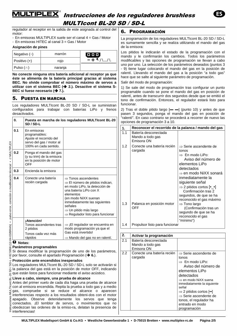
Instrucciones de los reguladores brushless MULTIcont BL-20 SD / SD-L
MULTIPLEX Modellsport GmbH & Co.KG • Westliche Ge werbestraße 1 • D-75015 Bretten • www.multiplex- rc.de Página 2/5
In
stru
ccio
nes
MU
LTIc
ont B
L-20
SD
/ S
D-L
# 8
2 59
58 (
12-0
4-03
/BR
AN
) •
¡sa
lvo
erro
r, c
orre
ción
o m
odifi
caci
ón té
cnic
a! •
M
ULT
IPLE
X
regulador al receptor en la salida de este asignada al control del motor: - En emisoras MULTIPLEX suele ser el canal 4 = Gas / Motor - En emisoras HITEC al canal 3 = Gas / Motor
Asignación de pines
Negativo (−) marrón
Positivo (+) rojo
Pulso ( ) naranja
No conecte ninguna otra batería adicional al recept or ya que éste se alimenta de la batería principal gracias al sistema BEC. No olvide comprobar el número máximo de servos a utilizar con el sistema BEC ( ���� 2.). Desactive el sistema S-BEC si fuese necesario ( ���� 7.).
5. PUESTA EN MARCHA Los reguladores MULTIcont BL-20 SD / SD-L se suministran configurados para trabajar con baterías LiPo y frenos desactivados.
0. Puesta en marcha de los reguladores MULTIcont B L-20 SD / SD-L
0.1 En emisoras programables: Ajuste el recorrido del servo del gas / motor al 100% en cada sentido.
0.2 Ponga el mando del gas (y su trim) de la emisora en la posición de motor OFF
0.3 Encienda la emisora
0.4 Conecte una batería recién cargada
⇒ Tonos ascendentes ⇒ El número de pitidos indican, en modo LiPo, la detección de una batería LiPo con X elementos (en modo NiXX suenan inmediatamente las siguientes señales ⇒ Un pitido más largo ⇒ Regulador listo para funcionar
¡Atención! Tonos ascendentes tras 2 pitidos Tonos cada vez más rápidos
⇒ ¡El regulador se encuentra en modo programación ya que el Gas está invertido!
⇒ Mando del gas no en ralentí.
! Notas: Parámetros programables Si desea modificar la programación de uno de los parámetros, por favor, consulte el apartado Programación (� 6.). Protección ante encendidos inesperados Los reguladores MULTIcont BL-20 SD / SD-L solo se activarán si la palanca del gas está en la posición de motor OFF, indicando que están listos para funcionar mediante el aviso acústico.
Lleve a cabo, siempre, una prueba de alcance Antes del primer vuelo de cada día haga una prueba de alcance con al emisora encendida. Repita la prueba a todo gas y a medio gas, compruebe si se reduce el alcance o aparecen interferencias respecto a los resultados obteni-dos con el motor apagado. Observe detenidamente los servos que tenga conectados. ¡El temblor de servos, o movimientos que no obedezcan las ordenes de la emiso-ra, delatan la presencia de interferencias!
6. PROGRAMACIÓN La programación de los reguladores MULTIcont BL-20 SD / SD-L es sumamente sencilla y se realiza utilizando el mando del gas de la emisora:
Los pitidos le indicarán el estado de la programación con el mando y le confirmarán los cambios. Todos los parámetros modificables y las opciones de programación se llevan a cabo uno por uno. La selección de los parámetros deseados (puntos 3 - 9) tiene lugar colocando el mando del gas en la posición de ralentí. Llevando el mando del gas a la posición “a todo gas" hace que se salte al siguiente parámetro de programación.
Salir del modo de programación:
1) Se sale del modo de programación tras configurar un punto programable cuando se pone el mando del gas en posición de ralentí, antes de transcurrir dos segundos desde que se emitió el tono de confirmación. Entonces, el regulador estará listo para funcionar.
2) Tras el doble pitido largo [▬ ▬] (punto 10) y antes de que pasen 3 segundos, ponga el mando del gas en posición de "ralentí". En caso contrario se procederá a recorrer de nuevo las opciones de programación 3 a 10.
1. Reconocer el recorrido de la palanca / mando del ga s 1.1 Batería desconectada
Mando a todo gas Emisora ON
1.2 Conecte una batería recién cargada
⇒ Serie ascendente de tonos ⇒ En modo LiPo: Aviso del número de elementos LiPo detectados ⇒ en modo NiXX sonará inmediatamente la siguiente señal ⇒ 2 pitidos cortos [•_•] Confirmación tras 2 segundos, de que se ha reconocido el gas máximo
1.3 Palanca en posición motor OFF
⇒ Tono largo (Confirmación tras un segundo de que se ha reconocido el gas “mínimo”)
1.4 Propulsor listo para funcionar
2. Activar la programación 2.1 Batería desconectada
Mando a todo gas Emisora ON
2.2 Conecte una batería recién cargada
⇒ Serie ascendente de tonos ⇒ En modo LiPo: Aviso del número de elementos LiPo detectados ⇒ en modo NiXX suena inmediatamente la siguiente señal ⇒ 2 pitidos cortos [••] ⇒ Serie ascendente de tonos, el regulador ha entrado en modo programación
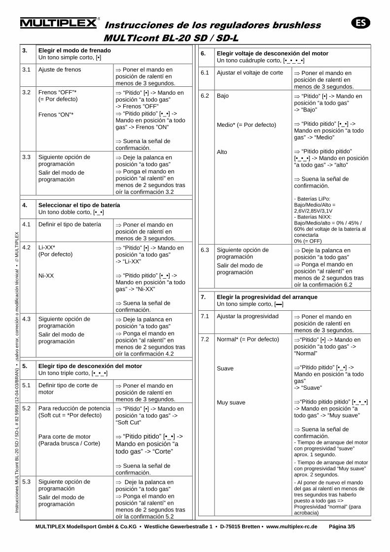
Instrucciones de los reguladores brushless MULTIcont BL-20 SD / SD-L
MULTIPLEX Modellsport GmbH & Co.KG • Westliche Ge werbestraße 1 • D-75015 Bretten • www.multiplex- rc.de Página 3/5
In
stru
ccio
nes
MU
LTIc
ont B
L-20
SD
/ S
D-L
# 8
2 59
58 (
12-0
4-03
/BR
AN
) •
¡sa
lvo
erro
r, c
orre
ción
o m
odifi
caci
ón té
cnic
a! •
M
ULT
IPLE
X
3. Elegir el modo de frenado Un tono simple corto, [•]
3.1 Ajuste de frenos ⇒ Poner el mando en posición de ralentí en menos de 3 segundos.
3.2 Frenos “OFF”* (= Por defecto)
Frenos “ON”*
⇒ “Pitido” [•] -> Mando en posición “a todo gas” -> Frenos ”OFF” ⇒ “Pitido pitido” [•_•] -> Mando en posición “a todo gas” -> Frenos ”ON” ⇒ Suena la señal de confirmación.
3.3 Siguiente opción de programación
Salir del modo de programación
⇒ Deje la palanca en posición “a todo gas” ⇒ Ponga el mando en posición “al ralentí” en menos de 2 segundos tras oír la confirmación 3.2
4. Seleccionar el tipo de batería Un tono doble corto, [•_•]
4.1 Definir el tipo de batería ⇒ Poner el mando en posición de ralentí en menos de 3 segundos.
4.2 Li-XX* (Por defecto)
Ni-XX
⇒ “Pitido” [•] -> Mando en posición “a todo gas” -> “Li-XX” ⇒ “Pitido pitido” [•_•] -> Mando en posición “a todo gas” -> “Ni-XX” ⇒ Suena la señal de confirmación.
4.3 Siguiente opción de programación
Salir del modo de programación
⇒ Deje la palanca en posición “a todo gas” ⇒ Ponga el mando en posición “al ralentí” en menos de 2 segundos tras oír la confirmación 4.2
5. Elegir tipo de desconexión del motor Un tono triple corto, [•_•_•]
5.1 Definir tipo de corte de motor
⇒ Poner el mando en posición de ralentí en menos de 3 segundos.
5.2 Para reducción de potencia (Soft cut = *Por defecto)
Para corte de motor (Parada brusca / Corte)
⇒ “Pitido” [•] -> Mando en posición “a todo gas” -> “Soft Cut” ⇒ “Pitido pitido” [•_•] -> Mando en posición “a todo gas” -> “Corte” ⇒ Suena la señal de confirmación.
5.3 Siguiente opción de programación
Salir del modo de programación
⇒ Deje la palanca en posición “a todo gas” ⇒ Ponga el mando en posición “al ralentí” en menos de 2 segundos tras oír la confirmación 5.2
6. Elegir voltaje de desconexión del motor Un tono cuádruple corto, [•_•_•_•]
6.1 Ajustar el voltaje de corte ⇒ Poner el mando en posición de ralentí en menos de 3 segundos.
6.2 Bajo
Medio* (= Por defecto) Alto
⇒ “Pitido” [•] -> Mando en posición “a todo gas” -> “Bajo” ⇒ “Pitido pitido” [•_•] -> Mando en posición “a todo gas” -> “Medio” ⇒ “Pitido pitido pitido” [•_•_•] -> Mando en posición “a todo gas” -> “alto” ⇒ Suena la señal de confirmación. - Baterías LiPo: Bajo/Medio/Alto = 2,6V/2,85V/3,1V - Baterías NiXX: Bajo/Medio/alto = 0% / 45% / 60% del voltaje de la batería al conectarla 0% (= OFF)
6.3 Siguiente opción de programación
Salir del modo de programación
⇒ Deje la palanca en posición “a todo gas” ⇒ Ponga el mando en posición “al ralentí” en menos de 2 segundos tras oír la confirmación 6.2
7. Elegir la progresividad del arranque Un tono simple corto, [▬]
7.1 Ajustar la progresividad ⇒ Poner el mando en posición de ralentí en menos de 3 segundos.
7.2 Normal* (= Por defecto)
Suave Muy suave
⇒“Pitido” [•] -> Mando en posición “a todo gas” -> “Normal” ⇒“Pitido pitido” [•_•] -> Mando en posición “a todo gas” -> “Suave” ⇒“Pitido pitido pitido” [•_•_•] -> Mando en posición “a todo gas” -> “Muy suave” ⇒ Suena la señal de confirmación. - Tiempo de arranque del motor con progresividad “suave” aprox. 1 segundo.
- Tiempo de arranque del motor con progresividad “Muy suave” aprox. 2 segundos.
- Al poner de nuevo el mando del gas al ralentí en menos de tres segundos tras haberlo puesto a todo gas => Progresividad “normal” (para acrobacia)
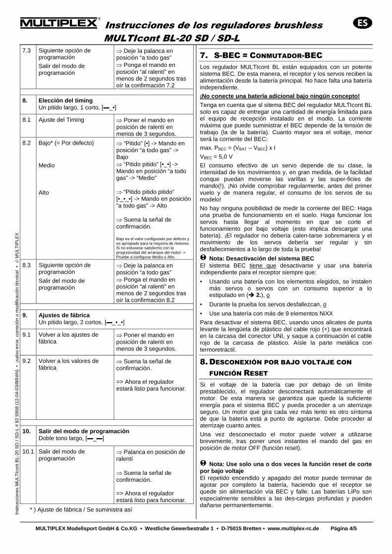
Instrucciones de los reguladores brushless MULTIcont BL-20 SD / SD-L
MULTIPLEX Modellsport GmbH & Co.KG • Westliche Ge werbestraße 1 • D-75015 Bretten • www.multiplex- rc.de Página 4/5
In
stru
ccio
nes
MU
LTIc
ont B
L-20
SD
/ S
D-L
# 8
2 59
58 (
12-0
4-03
/BR
AN
) •
¡sa
lvo
erro
r, c
orre
ción
o m
odifi
caci
ón té
cnic
a! •
M
ULT
IPLE
X
7.3 Siguiente opción de programación
Salir del modo de programación
⇒ Deje la palanca en posición “a todo gas” ⇒ Ponga el mando en posición “al ralentí” en menos de 2 segundos tras oír la confirmación 7.2
8. Elección del timing Un pitido largo, 1 corto, [▬_•]
8.1 Ajuste del Timing ⇒ Poner el mando en posición de ralentí en menos de 3 segundos.
8.2 Bajo* (= Por defecto)
Medio Alto
⇒ “Pitido” [•] -> Mando en posición “a todo gas” -> Bajo ⇒ “Pitido pitido” [•_•] -> Mando en posición “a todo gas” -> “Medio” ⇒ “Pitido pitido pitido” [•_•_•] -> Mando en posición “a todo gas” -> Alto ⇒ Suena la señal de confirmación. Bajo es el valor configurado por defecto y es apropiado para la mayoría de motores. Si no estuviese satisfecho con la progresividad del arranque del motor -> Pruebe a configurar Medio o Alto.
8.3 Siguiente opción de programación
Salir del modo de programación
⇒ Deje la palanca en posición “a todo gas” ⇒ Ponga el mando en posición “al ralentí” en menos de 2 segundos tras oír la confirmación 8.2
9. Ajustes de fábrica Un pitido largo, 2 cortos, [▬_•_•]
9.1 Volver a los ajustes de fábrica
⇒ Poner el mando en posición de ralentí en menos de 3 segundos.
9.2 Volver a los valores de fábrica
⇒ Suena la señal de confirmación. => Ahora el regulador estará listo para funcionar.
10. Salir del modo de programación Doble tono largo, [▬_▬]
10.1 Salir del modo de programación
⇒ Palanca en posición de ralentí ⇒ Suena la señal de confirmación. => Ahora el regulador estará listo para funcionar.
* ) Ajuste de fábrica / Se suministra así
7. S-BEC = CONMUTADOR-BEC Los regulador MULTIcont BL están equipados con un potente sistema BEC. De esta manera, el receptor y los servos reciben la alimentación desde la batería principal. No hace falta una batería independiente.
¡No conecte una batería adicional bajo ningún conce pto!
Tenga en cuenta que sl sitema BEC del regulador MULTIcont BL solo es capaz de entregar una cantidad de energía limitada para el equipo de recepción instalado en el modlo. La corriente máxima que puede suministrar el BEC depende de la tensión de trabajo (la de la batería). Cuanto mayor sea el voltaje, menor será la corriente del BEC:
max. PBEC = (VBAT – VBEC) x I
VBEC = 5,0 V
El consumo efectivo de un servo depende de su clase, la intensidad de los movimientos y, en gran medida, de la facilidad conque puedan moverse las varillas y las super-ficies de mando(!). ¡No olvide comprobar regularmente, antes del primer vuelo y de manera regular, el consumo de los servos de su modelo!
No hay ninguna posibilidad de medir la corriente del BEC: Haga una prueba de funcionamiento en el suelo. Haga funcionar los servos hasta llegar al momento en que se corte el funcionamiento por bajo voltaje (esto implica descargar una batería). ¡El regulador no debería calen-tarse sobremanera y el movimiento de los servos debería ser regular y sin desfallecimientos a lo largo de toda la prueba!
! Nota: Desactivación del sistema BEC El sistema BEC tiene que desactivarse y usar una batería independiente para el receptor siempre que:
• Usando una batería con los elementos elegidos, se instalen más servos o servos con un consumo superior a lo estipulado en (� 2.), o
• Durante la prueba los servos desfallezcan, o
• Use una batería con más de 9 elementos NiXX
Para desactivar el sistema BEC, usando unos alicates de punta levante la lengüeta de plástico del cable rojo (+) que encontrará en la carcasa del conector UNI, y saque a continuación el cable rojo de la carcasa de plástico. Aísle la parte metálica con termoretráctil.
8. DESCONEXIÓN POR BAJO VOLTAJE CON FUNCIÓN RESET
Si el voltaje de la batería cae por debajo de un límite prestablecido, el regulador desconectará automáticamente el motor. De esta manera se garantiza que quede la suficiente energía para el sistema BEC y pueda proceder a un aterrizaje seguro. Un motor que gira cada vez más lento es otro síntoma de que la batería está a punto de agotarse. Debe proceder al aterrizaje cuanto antes.
Una vez desconectado el motor puede volver a utilizarse brevemente, tras poner unos instantes el mando del gas en posición de motor OFF (función reset).
! Nota: Use solo una o dos veces la función reset de corte por bajo voltaje El repetido encendido y apagado del motor puede terminar de agotar por completo la batería, haciendo que el receptor se quede sin alimentación vía BEC y falle. Las baterías LiPo son especialmente sensibles a las des-cargas profundas y pueden dañarse permanentemente.
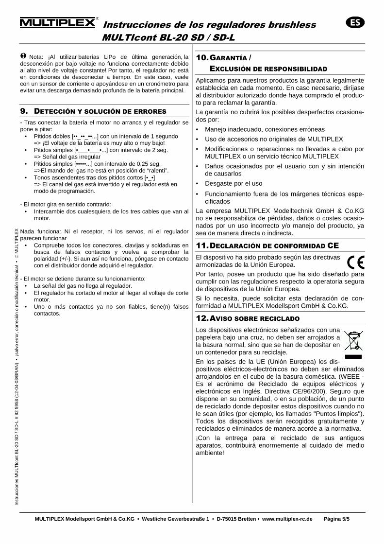
Instrucciones de los reguladores brushless MULTIcont BL-20 SD / SD-L
MULTIPLEX Modellsport GmbH & Co.KG • Westliche Ge werbestraße 1 • D-75015 Bretten • www.multiplex- rc.de Página 5/5
In
stru
ccio
nes
MU
LTIc
ont B
L-20
SD
/ S
D-L
# 8
2 59
58 (
12-0
4-03
/BR
AN
) •
¡sa
lvo
erro
r, c
orre
ción
o m
odifi
caci
ón té
cnic
a! •
M
ULT
IPLE
X
! Nota: ¡Al utilizar baterías LiPo de última generación, la desconexión por bajo voltaje no funciona correctamente debido al alto nivel de voltaje constante! Por tanto, el regulador no está en condiciones de desconectar a tiempo. En este caso, vuele con un sensor de corriente o apoyándose en un cronómetro para evitar una descarga demasiado profunda de la batería principal.
9. DETECCIÓN Y SOLUCIÓN DE ERRORES - Tras conectar la batería el motor no arranca y el regulador se pone a pitar:
• Pitidos dobles [••_••_••...] con un intervalo de 1 segundo => ¡El voltaje de la batería es muy alto o muy bajo!
• Pitidos simples [•___•___•...] con intervalo de 2 seg. => Señal del gas irregular
• Pitidos simples [•••••...] con intervalo de 0,25 seg. =>El mando del gas no está en posición de “ralentí”.
• Tonos ascendentes tras dos pitidos cortos [•_•] => El canal del gas está invertido y el regulador está en modo de programación.
- El motor gira en sentido contrario:
• Intercambie dos cualesquiera de los tres cables que van al motor.
Nada funciona: Ni el receptor, ni los servos, ni el regulador parecen funcionar
• Compruebe todos los conectores, clavijas y soldaduras en busca de falsos contactos y vuelva a comprobar la polaridad (+/-). Si aun así no funciona, póngase en contacto con el distribuidor donde adquirió el regulador.
- El motor se detiene durante su funcionamiento:
• La señal del gas no llega al regulador. • El regulador ha cortado el motor al llegar al voltaje de corte
motor. • Uno o más contactos ya no son fiables, tiene(n) falsos
contactos.
10. GARANTÍA / EXCLUSIÓN DE RESPONSIBILIDAD
Aplicamos para nuestros productos la garantía legalmente establecida en cada momento. En caso necesario, diríjase al distribuidor autorizado donde haya comprado el produc-to para reclamar la garantía.
La garantía no cubrirá los posibles desperfectos ocasiona-dos por:
• Manejo inadecuado, conexiones erróneas
• Uso de accesorios no originales de MULTIPLEX
• Modificaciones o reparaciones no llevadas a cabo por MULTIPLEX o un servicio técnico MULTIPLEX
• Daños ocasionados por el usuario con y sin intención de causarlos
• Desgaste por el uso
• Funcionamiento fuera de los márgenes técnicos espe-cificados
La empresa MULTIPLEX Modelltechnik GmbH & Co.KG no se responsabiliza de pérdidas, daños o costes ocasio-nados por un uso incorrecto y/o manejo del producto, ya sea de manera directa o indirecta.
11. DECLARACIÓN DE CONFORMIDAD CE El dispositivo ha sido probado según las directivas armonizadas de la Unión Europea.
Por tanto, posee un producto que ha sido diseñado para cumplir con las regulaciones respecto la operatoria segura de dispositivos de la Unión Europea.
Si lo necesita, puede solicitar esta declaración de con-formidad a MULTIPLEX Modellsport GmbH & Co.KG.
12. AVISO SOBRE RECICLADO Los dispositivos electrónicos señalizados con una papelera bajo una cruz, no deben ser arrojados a la basura normal, sino que se han de depositar en un contenedor para su reciclaje.
En los paises de la UE (Unión Europea) los dis-positivos eléctricos-electrónicos no deben ser eliminados arrojandolos en el cubo de la basura doméstica. (WEEE - Es el acrónimo de Reciclado de equipos eléctricos y electrónicos en Inglés. Directiva CE/96/200). Seguro que dispone en su comunidad, o en su población, de un punto de reciclado donde depositar estos dispositivos cuando no le sean útiles (por ejemplo, los llamados "Puntos limpios"). Todos los dispositivos serán recogidos gratuitamente y reciclados o eliminados de manera acorde a la normativa.
¡Con la entrega para el reciclado de sus antiguos aparatos, contribuirá enormemente al cuidado del medio ambiente!