Embed Size (px)
Citation preview

Multichannel STM-1 Service Module Installation and Configuration on Cisco 3900 Series Integrated Services RoutersProduct Number: SM-1-STM1-SM-C(=), SM-1-STM1-MM-C(=)
Americas HeadquartersCisco Systems, Inc.170 West Tasman DriveSan Jose, CA 95134-1706 USAhttp://www.cisco.comTel: 408 526-4000
800 553-NETS (6387)Fax: 408 527-0883
Text Part Number: OL-23027-01

THE SPECIFICATIONS AND INFORMATION REGARDING THE PRODUCTS IN THIS MANUAL ARE SUBJECT TO CHANGE WITHOUT NOTICE. ALL STATEMENTS, INFORMATION, AND RECOMMENDATIONS IN THIS MANUAL ARE BELIEVED TO BE ACCURATE BUT ARE PRESENTED WITHOUT WARRANTY OF ANY KIND, EXPRESS OR IMPLIED. USERS MUST TAKE FULL RESPONSIBILITY FOR THEIR APPLICATION OF ANY PRODUCTS.
THE SOFTWARE LICENSE AND LIMITED WARRANTY FOR THE ACCOMPANYING PRODUCT ARE SET FORTH IN THE INFORMATION PACKET THAT SHIPPED WITH THE PRODUCT AND ARE INCORPORATED HEREIN BY THIS REFERENCE. IF YOU ARE UNABLE TO LOCATE THE SOFTWARE LICENSE OR LIMITED WARRANTY, CONTACT YOUR CISCO REPRESENTATIVE FOR A COPY.
The following information is for FCC compliance of Class A devices: This equipment has been tested and found to comply with the limits for a Class A digital device, pursuant to part 15 of the FCC rules. These limits are designed to provide reasonable protection against harmful interference when the equipment is operated in a commercial environment. This equipment generates, uses, and can radiate radio-frequency energy and, if not installed and used in accordance with the instruction manual, may cause harmful interference to radio communications. Operation of this equipment in a residential area is likely to cause harmful interference, in which case users will be required to correct the interference at their own expense.
The following information is for FCC compliance of Class B devices: The equipment described in this manual generates and may radiate radio-frequency energy. If it is not installed in accordance with Cisco’s installation instructions, it may cause interference with radio and television reception. This equipment has been tested and found to comply with the limits for a Class B digital device in accordance with the specifications in part 15 of the FCC rules. These specifications are designed to provide reasonable protection against such interference in a residential installation. However, there is no guarantee that interference will not occur in a particular installation.
Modifying the equipment without Cisco’s written authorization may result in the equipment no longer complying with FCC requirements for Class A or Class B digital devices. In that event, your right to use the equipment may be limited by FCC regulations, and you may be required to correct any interference to radio or television communications at your own expense.
You can determine whether your equipment is causing interference by turning it off. If the interference stops, it was probably caused by the Cisco equipment or one of its peripheral devices. If the equipment causes interference to radio or television reception, try to correct the interference by using one or more of the following measures:
• Turn the television or radio antenna until the interference stops.
• Move the equipment to one side or the other of the television or radio.
• Move the equipment farther away from the television or radio.
• Plug the equipment into an outlet that is on a different circuit from the television or radio. (That is, make certain the equipment and the television or radio are on circuits controlled by different circuit breakers or fuses.)
Modifications to this product not authorized by Cisco Systems, Inc. could void the FCC approval and negate your authority to operate the product.
The Cisco implementation of TCP header compression is an adaptation of a program developed by the University of California, Berkeley (UCB) as part of UCB’s public domain version of the UNIX operating system. All rights reserved. Copyright © 1981, Regents of the University of California.
NOTWITHSTANDING ANY OTHER WARRANTY HEREIN, ALL DOCUMENT FILES AND SOFTWARE OF THESE SUPPLIERS ARE PROVIDED “AS IS” WITH ALL FAULTS. CISCO AND THE ABOVE-NAMED SUPPLIERS DISCLAIM ALL WARRANTIES, EXPRESSED OR IMPLIED, INCLUDING, WITHOUT LIMITATION, THOSE OF MERCHANTABILITY, FITNESS FOR A PARTICULAR PURPOSE AND NONINFRINGEMENT OR ARISING FROM A COURSE OF DEALING, USAGE, OR TRADE PRACTICE.
IN NO EVENT SHALL CISCO OR ITS SUPPLIERS BE LIABLE FOR ANY INDIRECT, SPECIAL, CONSEQUENTIAL, OR INCIDENTAL DAMAGES, INCLUDING, WITHOUT LIMITATION, LOST PROFITS OR LOSS OR DAMAGE TO DATA ARISING OUT OF THE USE OR INABILITY TO USE THIS MANUAL, EVEN IF CISCO OR ITS SUPPLIERS HAVE BEEN ADVISED OF THE POSSIBILITY OF SUCH DAMAGES.
Cisco and the Cisco Logo are trademarks of Cisco Systems, Inc. and/or its affiliates in the U.S. and other countries. A listing of Cisco's trademarks can be found at www.cisco.com/go/trademarks. Third party trademarks mentioned are the property of their respective owners. The use of the word partner does not imply a partnership relationship between Cisco and any other company. (1005R)
Multichannel STM-1 Service Module Installation and Configuration on Cisco 3900 Series Integrated Services Routers Copyright © 2010 Cisco Systems, Inc. All rights reserved.

Multichannel STM-1 Service ModuleOL-23027-01
C O N T E N T S
Preface 3
Objectives 1-4
Organization 1-4
Related Documentation 1-5
Obtaining Documentation, Obtaining Support, and Security Guidelines 1-5
C H A P T E R 1 Overview 1-1
Service Module Overview 1-1
SDH Overview 1-4
SM-1-STM1 Multiplexing Hierarchy 1-5
Features 1-5
SM-1-STM1 Optical Fiber Specifications 1-6
LEDs and Ports 1-7
Cables, Connectors, and Pinouts 1-8
Network Management 1-9
Service Module Slot Locations on the Cisco 3900 Series Integrated Services Routers 1-10
Cisco 3900 Series Routers Slot Numbering 1-10
Identifying Interface Addresses 1-10
C H A P T E R 2 Preparing for Installation 2-1
Required Tools and Equipment 2-1
Minimum Software and Hardware Requirements 2-1
Checking Hardware and Software Compatibility 2-2
Safety Guidelines 2-2
Warning Definition 2-2
Electrical Equipment Guidelines 2-8
Preventing Electrostatic Discharge Damage 2-8
Laser and LED Safety 2-8
FCC Class A Compliance 2-10
C H A P T E R 3 Removing and Installing Service Modules 3-1
Handling Service Modules 3-1
1 Installation and Configuration on Cisco 3900 Series Integrated Services Routers

REVIEW DRAF T—CISCO CO NF ID ENT IA L
Contents
Online Insertion and Removal 3-2
Warnings and Cautions 3-2
Equipment Installation Warning 3-2
Service Module Removal and Installation 3-3
Connecting a SM-1-STM1 Cable 3-3
C H A P T E R 4 Configuring the SM-1-STM1 4-1
Configuring the Interface 4-1
Shutting Down an Interface 4-2
Performing a Basic Interface Configuration 4-3
Configuring the AU-3s and TUG-3s of a SM-1-STM1 4-4
Configuring an E1 Unframed Channel 4-5
Checking the Configuration 4-5
Using show Commands to Verify the New Interface Status 4-5
Using the show controllers Commands 4-6
Using the show protocols Command 4-6
Using the show running-config Command 4-7
Using the show startup-config Command 4-7
Using the show version or show hardware Commands 4-9
Using the show diag Command 4-10
Using the show interfaces Command 4-11
Using the ping Command to Verify Network Connectivity 4-12
Using loopback Commands 4-12
IN D E X
2Multichannel STM-1 Service Module Installation and Configuration on Cisco 3900 Series Integrated Services Routers
OL-23027-01
Preface
This preface describes the objectives and organization of this document and explains how to find additional information on related products and services. This preface contains the following sections:
• Objectives, page 4
• Organization, page 4
• Related Documentation, page 5
• Obtaining Documentation, Obtaining Support, and Security Guidelines, page 5
3Multichannel STM-1 Service Module Installation and Configuration on Cisco 3900 Series Integrated Services Routers
OL-23027-01

PrefaceObjectives
ObjectivesThis document describes how to install and configure the multichannel STM-1 service module (SM-1-STM1-SM-C and SM-1-STM1-MM-C), hereafter referred to as the SM-1-STM1, which is used in the Cisco Integrated Services Routers Generation 2 (ISR G2), which include Cisco 3925, Cisco 3945, Cisco 3925E and Cisco 3945Erouters.
OrganizationThis document contains the following chapters:
Section Title Description
Chapter 1 Overview Describes the SM-1-STM1 and its LED displays, cables, and receptacles.
Chapter 2 Preparing for Installation Describes safety considerations, tools required, and procedures you should perform before the actual installation.
Chapter 3 Removing and Installing Service Modules
Describes the procedures for installing and removing SM-1-STM1 service modules in the supported platform.
Chapter 4 Configuring the SM-1-STM1 Provides instructions for configuring the SM-1-STM1 on the supported platform.
4Multichannel STM-1 Service Module Installation and Configuration on Cisco 3900 Series Integrated Services Routers
OL-23027-01

PrefaceRelated Documentation
Related DocumentationYour router and the Cisco IOS software running on it contain extensive features and functionality, which are documented in the following resources:
• Cisco IOS software configuration and hardware installation and maintenance documentation at http://www.cisco.com or http://www-china.cisco.com.
• Cisco 3925 and Cisco 3945 integrated services routers:
– To quickly access documents for the Cisco 3900 series ISRs, refer to the following URL:
http://www.cisco.com/en/US/products/ps10536/prod_installation_guides_list.html
• For international agency compliance, safety, and statutory information, refer to the following document:
– Regulatory Compliance and Safety Information for Cisco 3900 Series Integrated Services Routers
Obtaining Documentation, Obtaining Support, and Security Guidelines
For information on obtaining documentation, obtaining support, providing documentation feedback, security guidelines, and recommended aliases and general Cisco documents, see the monthly What’s New in Cisco Product Documentation, which also lists all new and revised technical documentation at:
http://www.cisco.com/en/US/docs/general/whatsnew/whatsnew.html
5Multichannel STM-1 Service Module Installation and Configuration on Cisco 3900 Series Integrated Services Routers
OL-23027-01

PrefaceObtaining Documentation, Obtaining Support, and Security Guidelines
6Multichannel STM-1 Service Module Installation and Configuration on Cisco 3900 Series Integrated Services Routers
OL-23027-01
Multichannel STM-1 Service Module Installation and ConfiguratioOL-23027-01
C H A P T E R1
OverviewThis chapter describes the SM-1-STM1 service modules (SM) and contains the following sections:
• Service Module Overview, page 1-1
• SDH Overview, page 1-4
• SM-1-STM1 Multiplexing Hierarchy, page 1-5
• Features, page 1-5
• SM-1-STM1 Optical Fiber Specifications, page 1-6
• LEDs and Ports, page 1-7
• Cables, Connectors, and Pinouts, page 1-8
• Network Management, page 1-9
• Service Module Slot Locations on the Cisco 3900 Series Integrated Services Routers, page 1-10
• Identifying Interface Addresses, page 1-10
Service Module OverviewThe SM-1-STM1-SM-C, shown in Figure 1-1, is a single-mode, high-speed, single-port multichannel STM-1 service module. SM-1-STM1-MM-C, shown in Figure 1-2, is a is a multi-mode, high-speed, single-port multichannel STM-1 service module. You can configure the SM-1-STM1 as a multichannel E1 STM-1 port, which can be configured into 63 individual E1 links. Each E1 link can carry a single channel at full or fractional rates, or it can be broken down into multiple DS0 rates.
The following restrictions exist:
• The maximum number of channels is limited to 226 per SM-1-STM1.
• This Cisco IOS software (Cisco IOS version 15.1(2)T) does not support more than two SM-1-STM1 SMs in the 3900 series ISRs.
• For OIR support, the STM-1 controller needs to be in a shutdown state before hot-swapping the module.
• Loopback support on the SONET controller is used for diagnostics only with no functional impact to the loopback feature. The following behavior is noted: Link is flapped on the peer interface when the SONET controller is set to loopback [local | network]. Using the shutdown/no shutdown command will overcome the link flap. Refer to “Shutting Down an Interface” section on page 4-2 for details on using the shutdown/no shutdown command.
1-1n on Cisco 3900 Series Integrated Services Routers

Chapter 1 Overview Service Module Overview
• The maximum number of FIFO buffers is 2048. The FIFO buffers are shared among the interfaces; how they are shared is determined by speed. If all the FIFO buffers have been assigned to existing interfaces, a new interface cannot be created, and the “%Insufficient FIFOs to create channel group” error message is seen. FIFO allocation information is provided in Table 1-1, and examples of supported and unsupported configurations are provided in Table 1-2 and Table 1-3.
Table 1-1 FIFO Allocation
Number of Timeslots Number of FIFO Buffers
1 3
2 3
2 3
4 4
5 5
6 6
7 7
8 9
9 9
10 10
11 12
12 12
13 16
14 16
15 16
16 16
17 17
18 18
19 20
20 20
21 21
22 22
23 24
24 24
25 25
26 26
27 28
28 28
29 29
30 30
31 32
Full E1 32
1-2Multichannel STM-1 Service Module Installation and Configuration on Cisco 3900 Series Integrated Services Routers
OL-23027-01

Chapter 1 Overview Service Module Overview
Following are three examples of supported and unsupported configurations.
The SM-1-STM1 supports up to three TUG-3/AU-3 transport slots numbered 1 to 3.
Figure 1-1 SM-1-STM1-SM-C—Faceplate View
Figure 1-2 SM-1-STM1-MM-C—Faceplate View
Table 1-2 Supported Configurations
Supported Configurations Total FIFO Buffers
63 E1s –> x 32 FIFOs = 2016
226 DSOs –> 226 x 3 FIFOs = 678
62 E1s + 21 DSOs –> (62 x 32) + (21 x 3) = 2047
Table 1-3 Unsupported Configurations
Unsupported Configurations Result
228 DS0s –> 226 interface limit is exceeded
62 E1s with 31 DSOs –> (62 x 32) + (31 x 3) = 2077 FIFOs (exceeds 2048 FIFO limit)
2491
7324
9174
1-3Multichannel STM-1 Service Module Installation and Configuration on Cisco 3900 Series Integrated Services Routers
OL-23027-01

Chapter 1 Overview SDH Overview
Figure 1-3 SM-1-STM1 Elements
SDH OverviewSynchronous Digital Hierarchy (SDH) is the international standard for optical digital transmission at hierarchical rates from 155.520 Mbps (STM-1) to 2.5 Gbps (STM-16) and greater.
The International Telecommunications Union Telecommunication Sector (ITU-T) defines a series of SDH transmission rates beginning at 155.520 Mbps as follows:
The SM-1-STM1 currently allows transmission over single-mode and multimode optical fiber only. Transmission rates are integral multiples of 51.840 Mbps, which can be used to carry E3 bit-synchronous signals.
Warning No user-serviceable parts inside. Do not open. Statement 1073
Warning Installation of the equipment must comply with local and national electrical codes. Statement 1074
1 Captive installation screw 2 Service module product name
3 Transmit out port 4 Laser warning label
5 Receive in port 6 Alarm LED
7 Rx Carrier LED 8 Product ID card
9 Enabled LED
2491
76
1 2 4 6
3 5 798
Table 1-4 SDH Transmission Rates
SDH Transmission Rate
STM-1 155.520 Mbps
STM-4 622.080 Mbps
STM-16 2,488.320 Mbps
STM-64 9,953.280 Mbps
1-4Multichannel STM-1 Service Module Installation and Configuration on Cisco 3900 Series Integrated Services Routers
OL-23027-01

Chapter 1 Overview SM-1-STM1 Multiplexing Hierarchy
Warning Use of controls, adjustments, or performing procedures other than those specified may result in hazardous radiation exposure. Statement 1057
SM-1-STM1 Multiplexing HierarchyFigure 1-4 illustrates the SDH multiplexing structure supported on the SM-1-STM1. The SM-1-STM1 multiplexing structure is a subset of that defined in ITU-T G.707. At the lowest level, containers (Cs) are input into virtual containers (VCs) with stuffing bits to create a uniform VC payload with a common bit-rate, ready for synchronous multiplexing. Then, the VCs are aligned into tributary units (TUs) where pointer processing operations are implemented, allowing the TUs to be multiplexed into TU groups (TUGs). Three TU-12s can be multiplexed into one TUG-2.
Figure 1-4 SM-1-STM1 Multiplexing Structure
The TUGs are then multiplexed into higher level VCs, which in turn are multiplexed into administration units (AUs). The AUs are then multiplexed into an AU group (AUG) and the final payload from the AUG is then multiplexed into the Synchronous Transport Module (STM).
FeaturesThe following is a list of features provided with the SM-1-STM1 service module:
• One channelized STM-1 port
• Channelized E1, fractional E1, and full-rate E1 supported
• Up to 226 usable channels allocated among the 63 E1 ports
• Internal or network clocking selectable on each E1
• 64 kbps DS0 time slots
• Line and payload loopback capabilities—local and network at the E1 and STM-1 level
• Full bit-error-rate testing capabilities on any E1
• Programmable pseudo-random pattern up to 32 bits in length, including 2 11-1; 2 15-1; and 2 20-1, 0153, and QRSS
• 32-bit error count and bit-count registers
• Detect test patterns conform to ITU-T 0.151 and 0.152 standards
• Online insertion and removal (OIR)
• Support for the following serial encapsulation protocols:
– Frame Relay
TU-12
TUG-2
TUG-3
E12.048 Mbps
C-12
x1
x1
x3
x1
VC-12
VC-4
VC-3 AU-3
AUG
x1
AU-4x3
x3x7
x7
STM-1
4790
2
1-5Multichannel STM-1 Service Module Installation and Configuration on Cisco 3900 Series Integrated Services Routers
OL-23027-01

Chapter 1 Overview SM-1-STM1 Optical Fiber Specifications
– PPP
– HDLC
• IP protocol support
• 16-bit or 32-bit CRC4 supported
• SDH / E1 functionality offered on the SM-1-STM1
Note SDH/E1 functionality may not be fully supported on the 3900 series ISRs.
SM-1-STM1 Optical Fiber Specifications The SM-1-STM1 specification for optical fiber transmission defines two types of fiber: single-mode and multimode. Within the single-mode category, two types of transmission are defined: intermediate reach and long reach. Within the multimode category, only short reach is available. (See Table 1-5 for specifications.)
Modes can be thought of as bundles of light rays entering the fiber at a particular angle. Single-mode fiber allows only one mode of light to propagate through the fiber at one wavelength and polarization, and multimode fiber allows multiple modes of light to propagate through the fiber for each wavelength and polarization.
Multiple modes of light propagating through the fiber travel different distances depending on the entry angles, which causes them to arrive at the destination at different times (a phenomenon called modal dispersion). Model dispersion limits propagation distance in multimode fiber before attenuation does. Therefore, single-mode fiber is capable of higher bandwidth and greater cable run distances than multimode fiber is. Table 1-5 lists nominal OC-3 optical parameters for single-mode and multimode optical fiber transmission.
Note If the distance between two connected stations is greater than the maximum distances listed, significant signal loss can result, making transmission unreliable.
Table 1-5 OC-3 Optical Parameters
Transceiver Type1
1. This table gives nominal OC-3 optical parameters.
Transmit Power
Maximum Power to Receiver2
2. This value represents the maximum power to which any receiver can be exposed.
Receiver Sensitivity
Loss Budgets
Nominal Distance Between Stations
Single-mode3 intermediate reach
3. Complies with ITU-T G.957 standard S.1-1 specification.
–15 dBm min. to –8 dBm max. at 1280–1335 nm
–8 dBm –28 dBm 0 to 12 dB Up to 9 mi (15 km)
Multimode4 short reach
4. Complies with Short-Reach OC-3 Specification SR-OC-3.
–20 dBm min. to –14 dBm max. at 1280–1335 nm
–8 dBm –23 dBm 0 to 7 dB Up to 1.2 mi (2 km)
1-6Multichannel STM-1 Service Module Installation and Configuration on Cisco 3900 Series Integrated Services Routers
OL-23027-01

Chapter 1 Overview LEDs and Ports
To calculate link losses and dispersion losses for your application, refer to the following specifications and documents:
• EIA/TIA-IVa Dispersion Unshifted Single-Mode Fiber
• EIA-TIA-IVb Dispersion Shifted Single-Mode Fiber
• GR-20-CORE Generic Requirements for Optical Fiber and Fiber-Optic Cable
• ITU-T Recommendation G.957 Optical Interfaces for Equipment and Systems Relating to the Synchronous Digital Hierarchy
LEDs and PortsFigure 1-5 shows the LEDs and Tx and Rx ports for the SM-1-STM1.
The green- or yellow-colored LEDs indicate service module status.
Figure 1-5 SM-1-STM1 LEDs
After system initialization, the ENABLED LED goes on to indicate that the SM has been enabled for operation.
The following conditions must be met before the SM-1-STM1 is enabled:
• The SM-1-STM1 is correctly connected and is receiving power.
• A valid system software image for the SM has been downloaded successfully.
• The system recognizes the SM-1-STM1.
If any of the above conditions are not met, or if the initialization fails for other reasons, the ENABLED LED does not go on.
Table 1-6 lists LED colors and indications.
1 Transmit out port 2 Receive in port
3 Alarm LED 4 Rx Carrier LED
5 Enabled LED
2492
13
3
1 2 4 5
Table 1-6 SM-1-STM1 LEDs
LED Label Color State Meaning
ENABLED Green On Service module is enabled for operation.
1-7Multichannel STM-1 Service Module Installation and Configuration on Cisco 3900 Series Integrated Services Routers
OL-23027-01
Chapter 1 Overview Cables, Connectors, and Pinouts
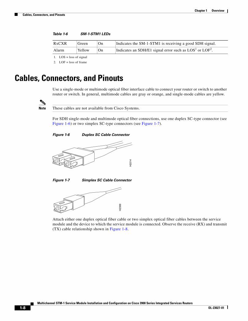
Cables, Connectors, and PinoutsUse a single-mode or multimode optical fiber interface cable to connect your router or switch to another router or switch. In general, multimode cables are gray or orange, and single-mode cables are yellow.
Note These cables are not available from Cisco Systems.
For SDH single-mode and multimode optical fiber connections, use one duplex SC-type connector (see Figure 1-6) or two simplex SC-type connectors (see Figure 1-7).
Figure 1-6 Duplex SC Cable Connector
Figure 1-7 Simplex SC Cable Connector
Attach either one duplex optical fiber cable or two simplex optical fiber cables between the service module and the device to which the service module is connected. Observe the receive (RX) and transmit (TX) cable relationship shown in Figure 1-8.
RxCXR Green On Indicates the SM-1-STM1 is receiving a good SDH signal.
Alarm Yellow On Indicates an SDH/E1 signal error such as LOS1 or LOF2.
1. LOS = loss of signal
2. LOF = loss of frame
Table 1-6 SM-1-STM1 LEDs
H22
14
H2 3
99
1-8Multichannel STM-1 Service Module Installation and Configuration on Cisco 3900 Series Integrated Services Routers
OL-23027-01

Chapter 1 Overview Network Management
Figure 1-8 Attaching Simplex or Duplex Optical Fiber Cables
The following warnings apply when you work with optical fiber cable ports.
Warning Invisible laser radiation may be emitted from the end of the unterminated fiber cable or connector. Do not view directly with optical instruments. Viewing the laser output with certain optical instruments (for example, eye loupes, magnifiers, and microscopes) within a distance of 100 mm may pose an eye hazard. Statement 1056
Warning Class 1 Laser Product. Statement 1008
Warning Class 1 LED Product. Statement 1027
Network ManagementTo locate MIBs and system messages associated with the SM-1-STM1 service module, see the following sites:
• The Error Message Decoder website allows you to determine the explanation and recommended action for an existing Cisco syslog message. You must be a registered Cisco.com user to access this document. To visit the Error Message Decoder website, go to this URL:
http://www.cisco.com/cgi-bin/Support/Errordecoder/home.pl
• You can find information about MIBs and OIDs at the Cisco IOS MIB Locator and SNMP Object Identifier website. The MIB Locator finds MIBs in Cisco IOS software releases. The SNMP Object Navigator translates OID's into SNMP names. To visit the Cisco IOS MIB Locator and SNMP Object Identifier website, go to this URL:
http://tools.cisco.com/ITDIT/MIBS/servlet/index
H76
82
SONET/SDH with simplex or duplex SC connectors
Simplex
Duplex
RX
TX
1-9Multichannel STM-1 Service Module Installation and Configuration on Cisco 3900 Series Integrated Services Routers
OL-23027-01

Chapter 1 Overview Service Module Slot Locations on the Cisco 3900 Series Integrated Services Routers
Service Module Slot Locations on the Cisco 3900 Series Integrated Services Routers
This section discusses service module slot locations on the supported platforms. The illustrations that follow summarize slot location conventions on each platform.
Cisco 3900 Series Routers Slot NumberingSee Overview of Cisco Network Modules and Service Modules for Cisco Access Routers general information and single- and double-wide slot numbering.
Figure 1-9 Cisco 3900 Series Router with Service Module Installed
Cisco 3945 series routers have four slots for service modules. You can place the service modules in any of the four slots.
Identifying Interface Addresses This section describes how to identify interface addresses for the SM-1-STM1. Interface addresses specify the actual physical location of each interface on the router.
Interfaces on a SM-1-STM1 installed in a router maintain the same address regardless of whether other service modules are installed or removed. However, when you move a service module to a different slot, the first number in the interface address changes to reflect the new service module slot number.
Note Interface ports on the Cisco 3945 series routers are numbered from bottom right to top left starting with 1.
Table 1-7 summarizes the interface address formats for the supported platforms.
2
1
4
3
ISM
EN
EN
SFPS
EN
S
L
S
L
USB
1
0
CONSOLE
AUX
GE 0/1
GE 0/2
GE0/0
SFP
S
EN
DO NOT REMOVE DURINGNETWORKING OPERATION
DO NOT REMOVE DURINGNETWORKING OPERATION
C3900-SPE100/K9
PVDM3 PVDM2 PVDM1 PVDM0
EHWIC 3
EHWIC 2
EHWIC 1
EHWIC 0
CF1
CF0
3945/3925SM SLOTSSPE
24
92
17
1-10Multichannel STM-1 Service Module Installation and Configuration on Cisco 3900 Series Integrated Services Routers
OL-23027-01

Chapter 1 Overview Identifying Interface Addresses
Table 1-7 Identifying Interface Addresses
Platform Interface Address Format Numbers Syntax
Cisco 3945 series ISRs
SM/slot-number Service module slot—1 through 4
Interface port—0
1/0
Cisco 3925 series ISRs
SM/slot-number Service module slot—1 through 2
Interface port—0
1/0
1-11Multichannel STM-1 Service Module Installation and Configuration on Cisco 3900 Series Integrated Services Routers
OL-23027-01

Chapter 1 Overview Identifying Interface Addresses
1-12Multichannel STM-1 Service Module Installation and Configuration on Cisco 3900 Series Integrated Services Routers
OL-23027-01

Multichannel STM-1 Service Module Installation and ConfiguratioOL-23027-01
C H A P T E R2
Preparing for InstallationThis chapter describes the general equipment, safety, and site preparation requirements for installing the SM-1-STM1. This chapter contains the following sections:
• Required Tools and Equipment, page 2-1
• Minimum Software and Hardware Requirements, page 2-1
• Checking Hardware and Software Compatibility, page 2-2
• Safety Guidelines, page 2-2
• Laser and LED Safety, page 2-8
• FCC Class A Compliance, page 2-10
Required Tools and EquipmentYou need the following tools and parts to install a SM-1-STM1. If you need additional equipment, contact a service representative for ordering information.
• SM-1-STM1SMI or SM-1-STM1MM
• One SC-type duplex or two SC-type simplex, multimode or single-mode optical fiber cables to connect the interface with the network. (Single-mode and multimode optical fiber cables for the SM-1-STM1 are not available from Cisco Systems but are available from commercial cable vendors. For information about optical fiber cables, see the “Cables, Connectors, and Pinouts” section on page 1-8.)
• Number 2 Phillips or a 3/16-inch flat-blade screwdriver
• Your own electrostatic discharge (ESD)-prevention equipment or the disposable grounding wrist strap included with all upgrade kits, field-replaceable units (FRUs), and spares
• Antistatic mat
• Antistatic container
Minimum Software and Hardware RequirementsThis section indicates the recommended minimum Cisco IOS software release required to use the SM-1-STM1 in supported platforms.
2-1n on Cisco 3900 Series Integrated Services Routers

Chapter 2 Preparing for Installation Checking Hardware and Software Compatibility
For the latest releases supporting the SM-1-STM1, refer to the “Checking Hardware and Software Compatibility” section on page 2-2.
Checking Hardware and Software CompatibilityTo check the minimum software requirements of Cisco IOS software with the hardware installed on your router, Cisco maintains the Software Advisor tool on Cisco.com. This tool does not verify whether modules within a system are compatible, but it does provide the minimum IOS requirements for individual hardware modules or components.
Note Access to this tool is limited to users with Cisco.com login accounts.
To access Software Advisor, go to: http://www.cisco.com/en/US/support/tsd_most_requested_tools.html.
Choose a product family or enter a specific product number to search for the minimum supported software release needed for your hardware.
Safety GuidelinesThis section provides safety guidelines that you should follow when working with any equipment that connects to electrical power or telephone wiring.
Warning DefinitionSafety warnings appear throughout this publication in procedures that, if performed incorrectly, may cause bodily harm. A warning symbol precedes each warning statement.
2-2Multichannel STM-1 Service Module Installation and Configuration on Cisco 3900 Series Integrated Services Routers
OL-23027-01

Chapter 2 Preparing for Installation Safety Guidelines
Warning IMPORTANT SAFETY INSTRUCTIONS
This warning symbol means danger. You are in a situation that could cause bodily injury. Before you work on any equipment, be aware of the hazards involved with electrical circuitry and be familiar with standard practices for preventing accidents. Use the statement number provided at the end of each warning to locate its translation in the translated safety warnings that accompanied this device. Statement 1071
SAVE THESE INSTRUCTIONS
Waarschuwing BELANGRIJKE VEILIGHEIDSINSTRUCTIES
Dit waarschuwingssymbool betekent gevaar. U verkeert in een situatie die lichamelijk letsel kan veroorzaken. Voordat u aan enige apparatuur gaat werken, dient u zich bewust te zijn van de bij elektrische schakelingen betrokken risico's en dient u op de hoogte te zijn van de standaard praktijken om ongelukken te voorkomen. Gebruik het nummer van de verklaring onderaan de waarschuwing als u een vertaling van de waarschuwing die bij het apparaat wordt geleverd, wilt raadplegen.
BEWAAR DEZE INSTRUCTIES
Varoitus TÄRKEITÄ TURVALLISUUSOHJEITA
Tämä varoitusmerkki merkitsee vaaraa. Tilanne voi aiheuttaa ruumiillisia vammoja. Ennen kuin käsittelet laitteistoa, huomioi sähköpiirien käsittelemiseen liittyvät riskit ja tutustu onnettomuuksien yleisiin ehkäisytapoihin. Turvallisuusvaroitusten käännökset löytyvät laitteen mukana toimitettujen käännettyjen turvallisuusvaroitusten joukosta varoitusten lopussa näkyvien lausuntonumeroiden avulla.
SÄILYTÄ NÄMÄ OHJEET
Attention IMPORTANTES INFORMATIONS DE SÉCURITÉ
Ce symbole d'avertissement indique un danger. Vous vous trouvez dans une situation pouvant entraîner des blessures ou des dommages corporels. Avant de travailler sur un équipement, soyez conscient des dangers liés aux circuits électriques et familiarisez-vous avec les procédures couramment utilisées pour éviter les accidents. Pour prendre connaissance des traductions des avertissements figurant dans les consignes de sécurité traduites qui accompagnent cet appareil, référez-vous au numéro de l'instruction situé à la fin de chaque avertissement.
CONSERVEZ CES INFORMATIONS
Warnung WICHTIGE SICHERHEITSHINWEISE
Dieses Warnsymbol bedeutet Gefahr. Sie befinden sich in einer Situation, die zu Verletzungen führen kann. Machen Sie sich vor der Arbeit mit Geräten mit den Gefahren elektrischer Schaltungen und den üblichen Verfahren zur Vorbeugung vor Unfällen vertraut. Suchen Sie mit der am Ende jeder Warnung angegebenen Anweisungsnummer nach der jeweiligen Übersetzung in den übersetzten Sicherheitshinweisen, die zusammen mit diesem Gerät ausgeliefert wurden.
BEWAHREN SIE DIESE HINWEISE GUT AUF.
2-3Multichannel STM-1 Service Module Installation and Configuration on Cisco 3900 Series Integrated Services Routers
OL-23027-01

Chapter 2 Preparing for Installation Safety Guidelines
Avvertenza IMPORTANTI ISTRUZIONI SULLA SICUREZZA
Questo simbolo di avvertenza indica un pericolo. La situazione potrebbe causare infortuni alle persone. Prima di intervenire su qualsiasi apparecchiatura, occorre essere al corrente dei pericoli relativi ai circuiti elettrici e conoscere le procedure standard per la prevenzione di incidenti. Utilizzare il numero di istruzione presente alla fine di ciascuna avvertenza per individuare le traduzioni delle avvertenze riportate in questo documento.
CONSERVARE QUESTE ISTRUZIONI
Advarsel VIKTIGE SIKKERHETSINSTRUKSJONER
Dette advarselssymbolet betyr fare. Du er i en situasjon som kan føre til skade på person. Før du begynner å arbeide med noe av utstyret, må du være oppmerksom på farene forbundet med elektriske kretser, og kjenne til standardprosedyrer for å forhindre ulykker. Bruk nummeret i slutten av hver advarsel for å finne oversettelsen i de oversatte sikkerhetsadvarslene som fulgte med denne enheten.
TA VARE PÅ DISSE INSTRUKSJONENE
Aviso INSTRUÇÕES IMPORTANTES DE SEGURANÇA
Este símbolo de aviso significa perigo. Você está em uma situação que poderá ser causadora de lesões corporais. Antes de iniciar a utilização de qualquer equipamento, tenha conhecimento dos perigos envolvidos no manuseio de circuitos elétricos e familiarize-se com as práticas habituais de prevenção de acidentes. Utilize o número da instrução fornecido ao final de cada aviso para localizar sua tradução nos avisos de segurança traduzidos que acompanham este dispositivo.
GUARDE ESTAS INSTRUÇÕES
¡Advertencia! INSTRUCCIONES IMPORTANTES DE SEGURIDAD
Este símbolo de aviso indica peligro. Existe riesgo para su integridad física. Antes de manipular cualquier equipo, considere los riesgos de la corriente eléctrica y familiarícese con los procedimientos estándar de prevención de accidentes. Al final de cada advertencia encontrará el número que le ayudará a encontrar el texto traducido en el apartado de traducciones que acompaña a este dispositivo.
GUARDE ESTAS INSTRUCCIONES
Varning! VIKTIGA SÄKERHETSANVISNINGAR
Denna varningssignal signalerar fara. Du befinner dig i en situation som kan leda till personskada. Innan du utför arbete på någon utrustning måste du vara medveten om farorna med elkretsar och känna till vanliga förfaranden för att förebygga olyckor. Använd det nummer som finns i slutet av varje varning för att hitta dess översättning i de översatta säkerhetsvarningar som medföljer denna anordning.
SPARA DESSA ANVISNINGAR
2-4Multichannel STM-1 Service Module Installation and Configuration on Cisco 3900 Series Integrated Services Routers
OL-23027-01
Chapter 2 Preparing for Installation Safety Guidelines
2-5Multichannel STM-1 Service Module Installation and Configuration on Cisco 3900 Series Integrated Services Routers
OL-23027-01

Chapter 2 Preparing for Installation Safety Guidelines
Aviso INSTRUÇÕES IMPORTANTES DE SEGURANÇA
Este símbolo de aviso significa perigo. Você se encontra em uma situação em que há risco de lesões corporais. Antes de trabalhar com qualquer equipamento, esteja ciente dos riscos que envolvem os circuitos elétricos e familiarize-se com as práticas padrão de prevenção de acidentes. Use o número da declaração fornecido ao final de cada aviso para localizar sua tradução nos avisos de segurança traduzidos que acompanham o dispositivo.
GUARDE ESTAS INSTRUÇÕES
Advarsel VIGTIGE SIKKERHEDSANVISNINGER
Dette advarselssymbol betyder fare. Du befinder dig i en situation med risiko for legemesbeskadigelse. Før du begynder arbejde på udstyr, skal du være opmærksom på de involverede risici, der er ved elektriske kredsløb, og du skal sætte dig ind i standardprocedurer til undgåelse af ulykker. Brug erklæringsnummeret efter hver advarsel for at finde oversættelsen i de oversatte advarsler, der fulgte med denne enhed.
GEM DISSE ANVISNINGER
2-6Multichannel STM-1 Service Module Installation and Configuration on Cisco 3900 Series Integrated Services Routers
OL-23027-01

Chapter 2 Preparing for Installation Safety Guidelines
2-7Multichannel STM-1 Service Module Installation and Configuration on Cisco 3900 Series Integrated Services Routers
OL-23027-01

Chapter 2 Preparing for Installation Laser and LED Safety
Electrical Equipment GuidelinesFollow these basic guidelines when working with any electrical equipment:
• Before beginning any procedures requiring access to the chassis interior, locate the emergency power-off switch for the room in which you are working.
• Disconnect all power and external cables before moving a chassis.
• Do not work alone when potentially hazardous conditions exist.
• Never assume that power has been disconnected from a circuit; always check.
• Do not perform any action that creates a potential hazard to people or makes the equipment unsafe; carefully examine your work area for possible hazards such as moist floors, ungrounded power extension cables, and missing safety grounds.
Preventing Electrostatic Discharge DamageElectrostatic discharge (ESD) damage, which can occur when electronic cards or components are improperly handled, results in complete or intermittent failures. Service modules and processor modules comprise printed circuit boards that are fixed in metal carriers. Electromagnetic interference (EMI) shielding and connectors are integral components of the carrier. Although the metal carrier helps to protect the board from ESD, use a preventive antistatic strap during handling.
Following are guidelines for preventing ESD damage:
• Always use an ESD wrist or ankle strap and ensure that it makes good skin contact.
• Connect the equipment end of the strap to an unfinished chassis surface.
• Handle carriers by available handles or edges only; avoid touching the printed circuit boards or connectors.
• Place a removed circuit board component-side-up on an antistatic surface or in a static shielding container. If you plan to return the component to the factory, immediately place it in a static shielding container.
• Avoid contact between the printed circuit boards and clothing. The wrist strap only protects components from ESD voltages on the body; ESD voltages on clothing can still cause damage.
• Never attempt to remove the printed circuit board from the metal carrier.
Caution For safety, periodically check the resistance value of the antistatic strap. The measurement should be between 1 and 10 megohms (Mohms).
Laser and LED SafetyThe single-mode transmitter in the module uses a small laser to transmit the light signal to the network ring. Keep the transmit port covered whenever a cable is not connected to it. Although multimode transceivers typically use LEDs for transmission, it is good practice to keep open ports covered and avoid staring into open ports or apertures. The single-mode aperture port contains a laser warning label, as shown in Figure 2-1.
2-8Multichannel STM-1 Service Module Installation and Configuration on Cisco 3900 Series Integrated Services Routers
OL-23027-01

Chapter 2 Preparing for Installation Laser and LED Safety
Figure 2-1 Laser Warning Labels for the SM-1-STM1-SM-C
Warning Class 1 laser product. Statement 1008.
Warning Invisible laser radiation may be emitted from disconnected fibers or connectors. Do not stare into beams or view directly with optical instruments. Statement 1051.
The multimode aperture contains a Class 1 LED warning label, as shown in Figure 2-2.
Figure 2-2 Laser Warning Labels for the SM-1-STM1-MM-C
Warning Class 1 LED product. Statement 1027.
Warning Invisible laser radiation may be emitted from the end of the unterminated fiber cable or connector. Do not view directly with optical instruments. Viewing the laser output with certain optical instruments (for example, eye loupes, magnifiers, and microscopes) within a distance of 100 mm may pose an eye hazard. Statement 1056
2492
1524
9216
2-9Multichannel STM-1 Service Module Installation and Configuration on Cisco 3900 Series Integrated Services Routers
OL-23027-01

Chapter 2 Preparing for Installation FCC Class A Compliance
FCC Class A ComplianceThis equipment has been tested and found to comply with the limits for a Class A digital device, pursuant to part 15 of the FCC rules. These limits are designed to provide reasonable protection against harmful interference when the equipment is operated in a commercial environment. This equipment generates, uses, and radiates radio-frequency energy and, if not installed and used in accordance with the instruction manual, may cause harmful interference to radio communications. Operation of this equipment in a residential area is likely to cause harmful interference, in which case users are required to correct the interference at their own expense.
You can determine whether your equipment is causing interference by turning it off. If the interference stops, it was probably caused by the Cisco equipment or one of its peripheral devices. If the equipment causes interference to radio or television reception, try to correct the interference by using one or more of the following measures:
• Turn the television or radio antenna until the interference stops.
• Move the equipment to one side of the television or radio.
• Move the equipment farther away from the television or radio.
• Plug the equipment into an outlet that is on a different circuit from the television or radio. (That is, make certain the equipment and the television or radio are on circuits controlled by different circuit breakers or fuses.)
Caution This product has been designed to meet FCC Class A compliance requirements. Modifications to this product that are not authorized by Cisco Systems, Inc. could void the various approvals and negate your authority to operate the product.
2-10Multichannel STM-1 Service Module Installation and Configuration on Cisco 3900 Series Integrated Services Routers
OL-23027-01

Multichannel STM-1 Service Module Installation and ConfiguratioOL-23027-01
C H A P T E R3
Removing and Installing Service ModulesThis chapter describes how to remove the SM-1-STM1 service module. This chapter contains the following sections:
• Handling Service Modules, page 3-1
• Online Insertion and Removal, page 3-2
• Warnings and Cautions, page 3-2
• Service Module Removal and Installation, page 3-3
• Connecting a SM-1-STM1 Cable, page 3-3
Handling Service ModulesEach service module circuit board is mounted to a metal carrier and is sensitive to electrostatic discharge (ESD) damage.
Note When a slot is not in use, a blank service module must fill the empty slot to allow the router to conform to electromagnetic interference (EMI) emissions requirements and to allow proper airflow across the service modules. If you plan to install a new service module in a slot that is not in use, you must first remove the blank service module.
Caution Always handle the service module by the carrier edges and handle; never touch the SM components or connector pins. (See Figure 3-1.)
Figure 3-1 Handling a Service Module
24
97
26
7300-CC-PA
OIRSTATUS
7300 PA CARRIER
ENAB
LED
RX C
ELLS
RX C
ARRI
ER
RX AL
ARM
ATM
3-1n on Cisco 3900 Series Integrated Services Routers

Chapter 3 Removing and Installing Service Modules Online Insertion and Removal
Online Insertion and Removal
Note As you disengage the service module from the router or switch, online insertion and removal (OIR) administratively shuts down all active interfaces in the service module. To properly perform OIR, follow the steps in the following URL: http://www.cisco.com/en/US/docs/routers/access/2900/hardware/installation/guide/appendix.html#wpxref68698
OIR allows you to install and replace service modules while the system is operating; you do not need to notify the software or reset the system power, although you should not run traffic through the service module you are removing while it is being removed. OIR is a method that is seamless to end users on the network, maintains all routing information, and ensures session preservation.
Note Before you begin installation, read Chapter 2, “Preparing for Installation,” for a list of parts and tools required for installation.
Warning Read the installation instructions before connecting the system to the power source. Statement 1004
Warnings and CautionsObserve the following caution when installing or removing modules:
Caution Be sure the service module is firmly seated in the router.
Equipment Installation Warning
Warning Only trained and qualified personnel should be allowed to install, replace, or service this equipment. Statement 1030
Warning Blank faceplates and cover panels serve three important functions: they prevent exposure to hazardous voltages and currents inside the chassis; they contain electromagnetic interference (EMI) that might disrupt other equipment; and they direct the flow of cooling air through the chassis. Do not operate the system unless all cards, faceplates, front covers, and rear covers are in place. Statement 1029
Warning Before working on equipment that is connected to power lines, remove jewelry (including rings, necklaces, and watches). Metal objects will heat up when connected to power and ground and can cause serious burns or weld the metal object to the terminals. Statement 43
3-2Multichannel STM-1 Service Module Installation and Configuration on Cisco 3900 Series Integrated Services Routers
OL-23027-01
Chapter 3 Removing and Installing Service Modules Service Module Removal and Installation
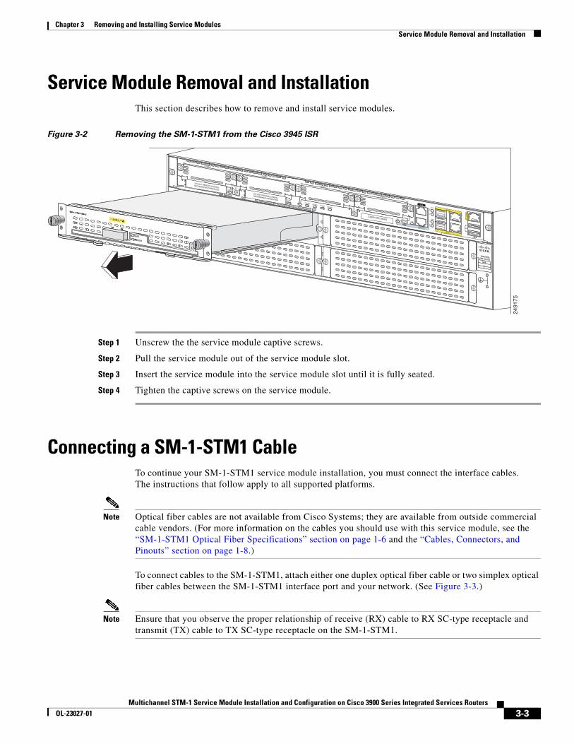
Service Module Removal and InstallationThis section describes how to remove and install service modules.
Figure 3-2 Removing the SM-1-STM1 from the Cisco 3945 ISR
Step 1 Unscrew the the service module captive screws.
Step 2 Pull the service module out of the service module slot.
Step 3 Insert the service module into the service module slot until it is fully seated.
Step 4 Tighten the captive screws on the service module.
Connecting a SM-1-STM1 CableTo continue your SM-1-STM1 service module installation, you must connect the interface cables. The instructions that follow apply to all supported platforms.
Note Optical fiber cables are not available from Cisco Systems; they are available from outside commercial cable vendors. (For more information on the cables you should use with this service module, see the “SM-1-STM1 Optical Fiber Specifications” section on page 1-6 and the “Cables, Connectors, and Pinouts” section on page 1-8.)
To connect cables to the SM-1-STM1, attach either one duplex optical fiber cable or two simplex optical fiber cables between the SM-1-STM1 interface port and your network. (See Figure 3-3.)
Note Ensure that you observe the proper relationship of receive (RX) cable to RX SC-type receptacle and transmit (TX) cable to TX SC-type receptacle on the SM-1-STM1.
2
1
4
3
ISM
EN
EN
SFPS
EN
S
L
S
L
USB
1
0
CONSOLE
AUX
GE 0/1
GE 0/2
GE0/0
SFP
S
EN
DO NOT REMOVE DURINGNETWORKING OPERATION
DO NOT REMOVE DURINGNETWORKING OPERATION
C3900-SPE100/K9
PVDM3 PVDM2 PVDM1 PVDM0
EHWIC 3
EHWIC 2
EHWIC 1
EHWIC 0
CF1
CF0
3945/3925SM SLOTSSPE
7300-CC-PA
OIRSTATUS
7300 PA CARRIER
ENAB
LED
RX C
ELLS
RX C
ARRI
ER
RX AL
ARM
ATM
24
91
75
3-3Multichannel STM-1 Service Module Installation and Configuration on Cisco 3900 Series Integrated Services Routers
OL-23027-01

Chapter 3 Removing and Installing Service Modules Connecting a SM-1-STM1 Cable
Figure 3-3 Connecting Simplex or Duplex Optical Fiber Cables to the SM-1-STM1
Warning Invisible laser radiation may be emitted from the end of the unterminated fiber cable or connector. Do not view directly with optical instruments. Viewing the laser output with certain optical instruments (for example, eye loupes, magnifiers, and microscopes) within a distance of 100 mm may pose an eye hazard. Statement 1056
Warning Class 1 Laser Product. Statement 1008.
Warning Class 1 LED Product. Statement 1027.
1 duplexconnector
(RX and TX)2 simplex
connectors
RX
TXor
24
92
14
3-4Multichannel STM-1 Service Module Installation and Configuration on Cisco 3900 Series Integrated Services Routers
OL-23027-01

Multichannel STM-1 Service Module Installation and ConfiguratioOL-23027-01
C H A P T E R4
Configuring the SM-1-STM1To continue your SM-1-STM1 service module installation, you must configure the STM-1 interface.
This chapter contains the following sections:
• Configuring the Interface, page 4-1
• Checking the Configuration, page 4-5
Configuring the Interface After you verify that the new SM-1-STM1 is installed correctly (the ENABLED LED is lit), use the privileged-level configure command to configure the new interface. Have the following information available:
• Protocols you plan to route on each new interface
• IP addresses, if you plan to configure the interfaces for IP routing
• Bridging protocols you plan to use
If you installed a new SM-1-STM1, or to change the configuration of an existing interface, you must enter configuration mode to configure the new interfaces. If you replaced a SM-1-STM1 that was previously configured, the system recognizes the new interfaces and brings each of them up in their existing configurations.
For a summary of the configuration options available and instructions for configuring interfaces on a SM-1-STM1, refer to the appropriate configuration publications listed in the “Related Documentation” section on page 5.
This section contains the following subsections:
• Shutting Down an Interface, page 4-2
• Performing a Basic Interface Configuration, page 4-3
• Configuring the AU-3s and TUG-3s of a SM-1-STM1, page 4-4
• Configuring an E1 Unframed Channel, page 4-5
• Using show Commands to Verify the New Interface Status, page 4-5
• Using the ping Command to Verify Network Connectivity, page 4-12
• Using loopback Commands, page 4-12
4-1n on Cisco 3900 Series Integrated Services Routers
Chapter 4 Configuring the SM-1-STM1 Configuring the Interface
Shutting Down an Interface Before you remove an interface that you will not replace, or replace service modules, use the shutdown command to shut down (disable) the interfaces to prevent anomalies when you reinstall the new or reconfigured SM. When you shut down an interface, it is designated administratively down in the show command displays.
SUMMARY STEPS
1. enable
2. configure terminal
3. interface serial slot/port
4. shutdown
5. copy running-config startup-config
6. show interfaces serial slot/port
4-2Multichannel STM-1 Service Module Installation and Configuration on Cisco 3900 Series Integrated Services Routers
OL-23027-01

Chapter 4 Configuring the SM-1-STM1 Configuring the Interface
DETAILED STEPS
Note To shut down additional interfaces, enter the interface serial command (followed by the interface address of the interface) for each of the interfaces on your SM. Use the no shutdown command to enable the interface.
Performing a Basic Interface Configuration Following are instructions for a basic configuration, which include enabling an interface and configuring the SONET controller. You might also need to enter other configuration subcommands, depending on the requirements for your system configuration and the protocols you plan to route on the interface. For complete descriptions of configuration subcommands and the configuration options available for SONET interfaces, refer to the appropriate software documentation.
In the following procedure, press the Enter key after each step unless otherwise noted. At any time you can exit the privileged level and return to the user level by entering disable at the prompt as follows:
Router# disable
Router>
Command or Action Purpose
Step 1 enable
Example:Router# enable
Enters privileged EXEC mode.
Step 2 configure terminal
Example:Router# configure terminal
Enters global configuration mode.
Step 3 interface serial slot/port
Example:Router(config-if)# interface serial 3/0
Enters interface configuration mode, and specifies an interface for configuration.
Step 4 shutdown
Example:Router(config-if)# shutdown
Shuts down the selected interface.
Step 5 copy running-config startup-config
Example:Router# copy running-config startup-config
Copies the new configuration to NVRAM.
Step 6 show interfaces serial slot/port
Example:Router# show interfaces serial 3/0
Confirms the interfaces have been shut down.
4-3Multichannel STM-1 Service Module Installation and Configuration on Cisco 3900 Series Integrated Services Routers
OL-23027-01

Chapter 4 Configuring the SM-1-STM1 Configuring the Interface
SUMMARY STEPS
1. enable
2. configure terminal
3. controller sonet slot/port
4. clock source {internal | line}
5. end
6. copy running-config startup-config
DETAILED STEPS
Configuring the AU-3s and TUG-3s of a SM-1-STM1You can configure each of the administrative unit groups (AUGs) and tributary unit groups (TUGs) of a SM-1-STM1 to carry a set of E1 links that are mapped into TU-12s (see Figure 4-1).
Command or Action Purpose
Step 1 enable
Example:Router# enable
Enters privileged EXEC mode.
Step 2 configure terminal
Example:Router# configure terminal
Enters global configuration mode.
Step 3 controller sonet slot/port
Example:Router(config)# controller sonet 3/0
Configures the SONET controller.
Note Follow this command by entering the interface address of the controller you plan to configure.
Step 4 clock source {internal | line}
Example:Router(config-controller)# clock source internal
Determines if clocking will be obtained locally from the SM-1-STM1 or from the network or line.
Step 5 end
Example:Router(config-controller)# end
Returns you to privileged EXEC mode.
Step 6 copy running-config startup-config
Example:Router# copy running-config startup-config
Copies the new configuration to NVRAM.
4-4Multichannel STM-1 Service Module Installation and Configuration on Cisco 3900 Series Integrated Services Routers
OL-23027-01

Chapter 4 Configuring the SM-1-STM1 Checking the Configuration
Figure 4-1 SM-1-STM1 Multiplexing Structure
Configuring an E1 Unframed ChannelTo create an unframed or clear channel logical channel group on an E1 line, use the tug-2 tug-2# e1 e1# unframed command, as shown in the example below:
Router(config)# controller sonet 3/0Router(config-controller)# au-4 1 tug-3 2Router(config-controller-tug3)# tug-2 4 e1 1 unframed
Note The channel group is always 0 for unframed E1 lines.
Checking the Configuration After configuring the new interface, use the show commands to display the status of the new interface or all interfaces, and use the ping and loopback commands to check connectivity. This section includes the following subsections:
• Using show Commands to Verify the New Interface Status, page 4-5
• Using the ping Command to Verify Network Connectivity, page 4-12
• Using loopback Commands, page 4-12
Using show Commands to Verify the New Interface StatusThis section demonstrates how you can use the show commands to verify that new interfaces are configured and operating correctly and that the module appears in them correctly. Sample displays of the output of selected show commands appear in the sections that follow. For complete command descriptions and examples, refer to the publications listed in the “Related Documentation” section on page 5.
If an interface is shut down and you configured it as up, or if the displays indicate that the hardware is not functioning properly, ensure that the interface is properly connected and terminated. If you still have problems bringing up the interface, contact a service representative for assistance.
This section includes the following subsections:
• Using the show controllers Commands, page 4-6
• Using the show protocols Command, page 4-6
• Using the show running-config Command, page 4-7
TU-12
TUG-2
TUG-3
E12.048 Mbps
C-12
x1
x1
x3
x1
VC-12
VC-4
VC-3 AU-3
AUG
x1
AU-4x3
x3x7
x7
STM-1
4790
2
4-5Multichannel STM-1 Service Module Installation and Configuration on Cisco 3900 Series Integrated Services Routers
OL-23027-01

Chapter 4 Configuring the SM-1-STM1 Checking the Configuration
• Using the show startup-config Command, page 4-7
• Using the show version or show hardware Commands, page 4-9
• Using the show diag Command, page 4-10
• Using the show interfaces Command, page 4-11
Using the show controllers Commands
Display all the current interface processors and their interfaces using the show controllers command.
Note The outputs that appear in this document may not match the output you receive when running these commands. The outputs in this document are examples only.
The following is an example of the show controllers command:
Router# show controllers sonet 1/0
SONET 1/0 is up. Hardware is single mode intermediate reach SM H/W Version : 24.257.2.5, ROM Version : 1.2, F/W Version : 1.19.0 FREEDM version: 2, reset 0 Applique type is Channelized Sonet/SDH Clock Source is Internal, AUG mapping is AU4.
Medium info: Type: SDH, Line Coding: NRZ, Line Type: Short SM
Regenerator Section Status: No alarms detected.
Multiplex Section Status:
No alarms detected. No BER failure/degrade detected BER_SF threshold power : 3 BER_SD threshold power : 6
Higher Order Path Status: Path# 1 has no defects
Lower Order Path Status: VC-12 1/1/1/1 has no defects
Using the show protocols Command
Display protocols configured for the entire system and for specific interfaces using the show protocols command.
Note The outputs that appear in this document may not match the output you receive when running these commands. The outputs in this document are examples only.
The following is an example of the show protocols command:
Router# show protocolsline protocol is up
4-6Multichannel STM-1 Service Module Installation and Configuration on Cisco 3900 Series Integrated Services Routers
OL-23027-01

Chapter 4 Configuring the SM-1-STM1 Checking the Configuration
Using the show running-config Command
Display the running configuration file using the show running-config command.
Note The outputs that appear in this document may not match the output you receive when running these commands. The outputs in this document are examples only.
The following is an example of the show running-config command:
Router# show running-config
controller SONET 1/0 framing sdh ! au-4 1 tug-3 1 tug-2 1 e1 1 channel-group 1 timeslots 1-3
interface Serial1/0.1/1/1/1:1 ip address 1.1.1.1 255.255.255.0
Using the show startup-config Command
Display the configuration stored in the NVRAM using the show startup-config command.
Note The outputs that appear in this document may not match the output you receive when running these commands. The outputs in this document are examples only.
The following is an example of the show startup-config command:
Router# show startup-configBuilding configuration...
Current configuration : 27478 bytes!! Last configuration change at 13:23:45 IST Mon Jun 21 2010!version 15.1service timestamps debug datetime msec localtime show-timezoneservice timestamps log datetime msec localtime show-timezoneno service password-encryption!hostname 3945_PGIRI!boot-start-markerboot-end-marker!!enable password lab!no aaa new-modelclock timezone IST 5 0!no ipv6 cefip source-route
4-7Multichannel STM-1 Service Module Installation and Configuration on Cisco 3900 Series Integrated Services Routers
OL-23027-01

Chapter 4 Configuring the SM-1-STM1 Checking the Configuration
ip cef !!!!!multilink bundle-name authenticated!!energywise domain cisco security shared-secret 0 cisco!crypto pki token default removal timeout 0!!license udi pid C3900-SPE150/K9 sn FOC13522K4K!!!!controller SHDSL 0/0/0 termination co dsl-group pairs 0 !controller SONET 1/0 framing sdh clock source internal ! au-4 1 tug-3 1 tug-2 1 e1 1 channel-group 1 timeslots 1-31 ! au-4 1 tug-3 2 tug-2 2 e1 1 unframed ! au-4 1 tug-3 3 tug-2 1 e1 3 channel-group 30 timeslots 1 tug-2 3 e1 2 channel-group 17 timeslots 17!interface GigabitEthernet0/0 ip address 209.165.200.225 255.255.255.224 duplex auto speed auto!interface GigabitEthernet0/1 mtu 1600 no ip address shutdown duplex auto speed auto!interface GigabitEthernet0/2 mtu 1600 no ip address shutdown duplex auto speed auto!interface Ethernet0/0/0 no ip address tx-ring-limit 1 tx-queue-limit 1!interface Serial0/3/0 ip address 209.165.200.254 255.255.255.224!
4-8Multichannel STM-1 Service Module Installation and Configuration on Cisco 3900 Series Integrated Services Routers
OL-23027-01

Chapter 4 Configuring the SM-1-STM1 Checking the Configuration
! ip forward-protocol nd!no ip http serverno ip http secure-server!ip route 0.0.0.0 0.0.0.0 GigabitEthernet0/0ip route 2209.165.201.1 255.255.255.224 209.165.201.30!!!snmp-server community public RW!control-plane!!line con 0 exec-timeout 0 0line aux 0line vty 0 4 login transport input all!!exception data-corruption buffer truncatescheduler allocate 20000 1000end
Using the show version or show hardware Commands
Display the configuration of the system hardware, the number of each interface type installed, the Cisco IOS software version, the names and sources of configuration files, and the boot images, using the show version (or show hardware) command.
Note The outputs that appear in this document may not match the output you receive when running these commands. The outputs in this document are examples only.
Example Output of the show version Command
Following is an example of the show version command from a Cisco 3945 ISR router with a SM-1-STM1 installed:
Router# show version
Cisco IOS Software, C3900 Software (C3900-UNIVERSALK9-M), 15.1(20100617:043914) Copyright (c) 1986-2010 by Cisco Systems, Inc.Compiled Thu 17-Jun-10 11:54 by anybody
ROM: System Bootstrap, Version 15.0(1r)M1, RELEASE SOFTWARE (fc1)
3945_PGIRI uptime is 5 hours, 5 minutesSystem returned to ROM by reload at 08:16:36 IST Mon Jun 21 2010System image file is "flash:c3900-universalk9-mz.SSA.last"Last reload type: Normal ReloadLast reload reason: Reload Command
4-9Multichannel STM-1 Service Module Installation and Configuration on Cisco 3900 Series Integrated Services Routers
OL-23027-01
Chapter 4 Configuring the SM-1-STM1 Checking the Configuration
This product contains cryptographic features and is subject to UnitedStates and local country laws governing import, export, transfer anduse. Delivery of Cisco cryptographic products does not implythird-party authority to import, export, distribute or use encryption.Importers, exporters, distributors and users are responsible forcompliance with U.S. and local country laws. By using this product youagree to comply with applicable laws and regulations. If you are unableto comply with U.S. and local laws, return this product immediately. A summary of U.S. laws governing Cisco cryptographic products may be found at:http://www.cisco.com/wwl/export/crypto/tool/stqrg.html
If you require further assistance please contact us by sending email [email protected].
Cisco CISCO3945-CHASSIS (revision 1.0) with C3900-SPE150/K9 with 980992K/67584K bytes of memory.Processor board ID FHK1402F1YL1 DSL controller1 Ethernet interface3 Gigabit Ethernet interfaces231 Serial interfaces2 Channelized STM-1 portsDRAM configuration is 72 bits wide with parity enabled.255K bytes of non-volatile configuration memory.126448K bytes of USB Flash usbflash0 (Read/Write)254464K bytes of ATA System CompactFlash 0 (Read/Write)
License Info: License UDI:
-------------------------------------------------Device# PID SN-------------------------------------------------*0 C3900-SPE150/K9 FOC13522K4K
Technology Package License Information for Module:'c3900'
----------------------------------------------------------------Technology Technology-package Technology-package Current Type Next reboot -----------------------------------------------------------------ipbase ipbasek9 Permanent ipbasek9security None None Noneuc None None Nonedata None None None
Configuration register is 0x0
Using the show diag Command
Display the types of service modules installed in your system (and specific information about each) using the show diag slot command, where slot is the service module slot in a Cisco 3925 router or Cisco 3945 router.
4-10Multichannel STM-1 Service Module Installation and Configuration on Cisco 3900 Series Integrated Services Routers
OL-23027-01

Chapter 4 Configuring the SM-1-STM1 Checking the Configuration
Note The outputs that appear in this document may not match the output you receive when running these commands. The outputs in this document are examples only.
Using the show interfaces Command
Display status information (including the physical slot and interface address) for the interfaces you specify using the show interfaces command.
For complete descriptions of interface subcommands and the configuration options available for the supported interfaces, refer to the publications listed in the “Related Documentation” section on page 5.
Note The outputs that appear in this document may not match the output you receive when running these commands. The outputs in this document are examples only.
Example Output of the show interfaces Command
Following is an example of the show interfaces command from a Cisco 3945 ISR with a SM-1-STM1 installed:
Router> show interface serial
Router#sh int Serial1/0.1/1/1/1:1Serial1/0.1/1/1/1:1 is up, line protocol is up Hardware is Channelized STM-1 controller Internet address is 1.1.1.2/24 MTU 1500 bytes, BW 192 Kbit/sec, DLY 20000 usec, reliability 255/255, txload 1/255, rxload 65/255 Encapsulation HDLC, crc 16, loopback not set Keepalive set (10 sec) Last input 00:00:00, output never, output hang never Last clearing of "show interface" counters never Input queue: 0/75/0/0 (size/max/drops/flushes); Total output drops: 0 Queueing strategy: weighted fair Output queue: 0/1000/64/0 (size/max total/threshold/drops) Conversations 0/1/16 (active/max active/max total) Reserved Conversations 0/0 (allocated/max allocated) Available Bandwidth 144 kilobits/sec 5 minute input rate 49000 bits/sec, 23 packets/sec 5 minute output rate 0 bits/sec, 0 packets/sec 5507 packets input, 1785932 bytes, 0 no buffer Received 30 broadcasts (0 IP multicasts) 0 runts, 0 giants, 0 throttles 0 input errors, 0 CRC, 0 frame, 0 overrun, 0 ignored, 0 abort 35 packets output, 2995 bytes, 0 underruns 0 output errors, 0 collisions, 1 interface resets 0 unknown protocol drops 0 output buffer failures, 0 output buffers swapped out 0 carrier transitions no alarm present Timeslot(s) Used: 1-3, subrate: 192Kb/s, transmit delay is 0 flags non-inverted dataRouter#
4-11Multichannel STM-1 Service Module Installation and Configuration on Cisco 3900 Series Integrated Services Routers
OL-23027-01

Chapter 4 Configuring the SM-1-STM1 Checking the Configuration
Using the ping Command to Verify Network ConnectivityUsing the ping command, you can verify that an interface port is functioning properly. This section provides a brief description of this command. Refer to the publications listed in the “Related Documentation” section on page 5 for detailed command descriptions and examples.
The ping command sends echo request packets out to a remote device at an IP address that you specify. After sending an echo request, the system waits a specified time for the remote device to reply. Each echo reply is displayed as an exclamation point (!) on the console terminal; each request that is not returned before the specified timeout is displayed as a period (.). A series of exclamation points (!!!!!) indicates a good connection; a series of periods (.....) or the messages [timed out] or [failed] indicate a bad connection.
Following is an example of a successful ping command to a remote server with the address 10.0.0.10:
Router# ping 10.0.0.10 <Return>Type escape sequence to abort.Sending 5, 100-byte ICMP Echoes to 10.0.0.10, timeout is 2 seconds:!!!!!Success rate is 100 percent (5/5), round-trip min/avg/max = 1/15/64 msRouter#
If the connection fails, verify that you have the correct IP address for the destination and that the device is active (powered on), and repeat the ping command.
Proceed to the, “Using loopback Commands” section on page 4-12, to finish checking network connectivity.
Using loopback CommandsWith the loopback test, you can detect and isolate equipment malfunctions by testing the connection between the SM-1-STM1 interface and a remote device such as a multiplexer interface. The loopback subcommand places an interface in loopback mode, which enables test packets that are generated from the ping command to loop through a remote device. If the packets complete the loop, the connection is good. If not, you can isolate a fault to the remote device in the path of the loopback test.
The SM-1-STM1 supports two loopback modes at the sonet controller level: local and network.
Use the loopback {local | network} command to set the loopback mode, as shown below:
Router(config)# controller sonet 3/0Router(config-controller)# loopback network
When the loopback local command is used, all data transmitted to the network is internally looped back to the receiver. In this loopback mode, the serial interfaces should go into up/up looped state.
When the loopback network command is used, all data received from the connected device is transmitted back unchanged. In this loopback mode, T1 serial interfaces are not working.
The SM-1-STM1 also supports loopback on E1 lines mapped to a TUG-3 or AU-3.
To specify a loopback on an E1 line that has been mapped to a TUG-3, use the tug-2 e1 loopback command in configuration controller tug3 mode.
To specify a loopback on an E1 line that has been mapped to an AU-3, use the tug-2 e1 loopback command in configuration controller au3 mode.
The complete tug-2 e1 loopback command syntax is:
tug-2 tug-2 number e1 e1-number loopback {local | network {line | payload}}
4-12Multichannel STM-1 Service Module Installation and Configuration on Cisco 3900 Series Integrated Services Routers
OL-23027-01

Chapter 4 Configuring the SM-1-STM1 Checking the Configuration
To disable the loopback, use the no form of this command:
[no] tug-2 tug-2 number e1 e1-number loopback {local | network {line | payload}}
4-13Multichannel STM-1 Service Module Installation and Configuration on Cisco 3900 Series Integrated Services Routers
OL-23027-01

Chapter 4 Configuring the SM-1-STM1 Checking the Configuration
4-14Multichannel STM-1 Service Module Installation and Configuration on Cisco 3900 Series Integrated Services Routers
OL-23027-01

Multichannel STM-1 Service Module Installation and ConfiguratioOL-23027-01
I N D E X
Numerics
4E
service module LEDs 1-7
E
electrical equipment guidelines 2-8
electrostatic discharge damage
See ESD prevention
ESD prevention 2-8
I
installation
VIP prerequisites 2-1
interface processor
installation prerequisites 2-1
tools and parts required for installation 2-1
L
LEDs
4E service module 1-7
P
parts required for VIP installation and maintenance 2-1
prerequisites
VIP installation 2-1
R
RJ-45
4E
cable attachment 3-3
S
safety guidelines 2-2
service module
4E
LEDs 1-7
T
tools required for VIP installation and maintenance 2-1
IN-1n on Cisco 3900 Series Integrated Services Routers

Index
IN-2Multichannel STM-1 Service Module Installation and Configuratio
n on Cisco 3900 Series Integrated Services RoutersOL-23027-01