Embed Size (px)
Citation preview

Recommendation ITU-R BS.775-3(08/2012)
Multichannel stereophonic sound system with and without accompanying picture
BS SeriesBroadcasting service (sound)
ii Rec. ITU-R BS.775-3
Foreword
The role of the Radiocommunication Sector is to ensure the rational, equitable, efficient and economical use of the radio-frequency spectrum by all radiocommunication services, including satellite services, and carry out studies without limit of frequency range on the basis of which Recommendations are adopted.
The regulatory and policy functions of the Radiocommunication Sector are performed by World and Regional Radiocommunication Conferences and Radiocommunication Assemblies supported by Study Groups.
Policy on Intellectual Property Right (IPR)
ITU-R policy on IPR is described in the Common Patent Policy for ITU-T/ITU-R/ISO/IEC referenced in Annex 1 of Resolution ITU-R 1. Forms to be used for the submission of patent statements and licensing declarations by patent holders are available from http://www.itu.int/ITU-R/go/patents/en where the Guidelines for Implementation of the Common Patent Policy for ITU-T/ITU-R/ISO/IEC and the ITU-R patent information database can also be found.
Series of ITU-R Recommendations (Also available online at http://www.itu.int/publ/R-REC/en)
Series Title
BO Satellite delivery BR Recording for production, archival and play-out; film for television BS Broadcasting service (sound) BT Broadcasting service (television) F Fixed service M Mobile, radiodetermination, amateur and related satellite services P Radiowave propagation RA Radio astronomy RS Remote sensing systems S Fixed-satellite service SA Space applications and meteorology SF Frequency sharing and coordination between fixed-satellite and fixed service systems SM Spectrum management SNG Satellite news gathering TF Time signals and frequency standards emissions V Vocabulary and related subjects
Note: This ITU-R Recommendation was approved in English under the procedure detailed in Resolution ITU-R 1.
Electronic Publication Geneva, 2012
© ITU 2012
All rights reserved. No part of this publication may be reproduced, by any means whatsoever, without written permission of ITU.
Rec. ITU-R BS.775-3 1
RECOMMENDATION ITU-R BS.775-3*, **
Multichannel stereophonic sound system with and without accompanying picture
(1992-1994-2006-2012)
Scope
Digital TV has rapidly gained ground around the world. Several digital television broadcasting services have already been introduced in the terrestrial and in the satellite bands. As part of these digital broadcasting services, multichannel audio services are used or have been specified to enhance the directional stability of the frontal sound image and the sensation of spatial reality (ambience).
Recommendation ITU-R BS.775 recommends one universal multichannel stereophonic sound system with three front channels and two rear/side channels together with an optional low frequency effects (LFE) channel.
The ITU Radiocommunication Assembly,
considering a) that it is widely recognized that a two-channel sound system has serious limitations and improved presentation is necessary;
b) that the requirements of cinema presentation differ from those that apply in the home, particularly with respect to room and screen size and distribution of listeners, but that the same programmes may be reproduced in either the cinema or the home;
c) that broadcast HDTV signals, and those delivered by other media, should be capable of giving appropriate sound quality with a wide range of domestic loudspeaker configurations, including compatibility with two-channel stereophonic and monophonic listening;
d) that for multichannel sound it is desirable to separate the requirements of production, delivery and domestic presentation, though these are mutually interacting;
e) that investigations about multichannel sound transmission and reproduction associated and not associated with accompanying picture are being carried out with the basic requirements;
f) that one universal multichannel sound system applicable to both sound and television broadcasting would be beneficial to the listener;
g) that compromises may be necessary to ensure that the system is as universal and as practical as possible;
h) that a hierarchy of compatible sound systems for broadcasting, cinema and recordings is useful for programme exchange and up- and down-mixing depending on the programme material;
* This Recommendation should be brought to the attention of the International Electrotechnical
Commission (IEC) and the Society of Motion Picture and Television Engineers (SMPTE). ** Radiocommunication Study Group 6 made editorial amendments to this Recommendation in
November 2009 in accordance with Resolution ITU-R 1.
2 Rec. ITU-R BS.775-3
j) that ancillary services such as those for the visually impaired and hearing impaired are desirable;
k) that advances in digital audio coding currently allow the delivery of multiple audio channels in an efficient manner,
recommends 1 the universal multichannel stereophonic sound system, with or without accompanying picture, within a hierarchy given in Annex 1;
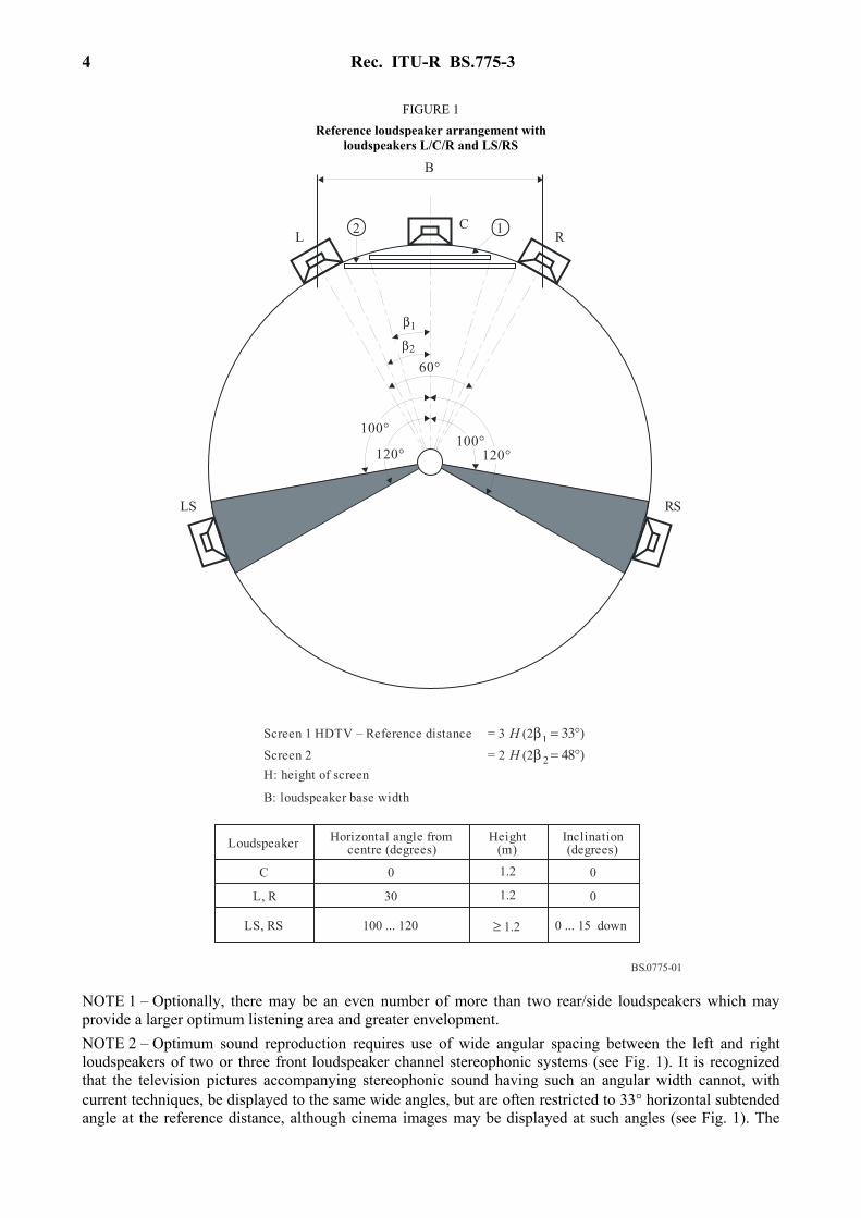
2 the following reference loudspeaker arrangement (see Fig. 1): – three front loudspeakers combined with two rear/side loudspeakers (Note 1); – the left and right frontal loudspeakers are placed at the extremities of an arc subtending 60°
at the reference listening point (Notes 2 and 3). Where for reasons of available space, it is preferred to place the frontal loudspeakers on a straight line base, then it may be necessary to introduce compensating time delays in the signal feed of the centre loudspeaker;
– both side/rear loudspeakers should be placed within the sectors from 100° to 120° from the centre front reference. Precise location is not necessary. Side/rear loudspeakers should be no closer to the listener than the frontal loudspeakers, unless compensating time delay is introduced (Notes 4 and 5);
– the acoustic centre of frontal loudspeakers should ideally be at a height approximately equal to that of the listener’s ears. This implies an acoustically transparent screen. Where a non-acoustically transparent screen is used, the centre loudspeaker should be placed immediately above or below the picture. The height of side/rear loudspeakers is less critical;
3 the use of five reference recording/transmission signals for left (L), right (R), centre (C), channels for the front, and left surround (LS) and right surround (RS) channels for the side/rear. Additionally the system may include a low frequency effects signal for a low frequency effects (LFE) channel any use of which should take into account the information provided in Annex 7 and Appendix 1 of Annex 7.
In circumstances where transmission capacity or other constraints apply, the LS and RS signals can be combined with one (mono surround, MS) or zero rear/side signals. In the case of mono surround, the MS signal is fed to both LS and RS loudspeakers (see Fig. 1);
4 that in the international exchange of audio or television programmes that use an audio format which offers a low-frequency effects (LFE) channel, the LFE channel should be band-limited to its nominal frequency band (up to120 Hz);
5 that broadcast of any television programme that contains an LFE channel should not transmit any information on that channel above the nominal 120 Hz cutoff frequency;
6 compatibility, if required, with existing and low cost receivers by using one of the methods given in Annex 3;
7 down-mixing capability, if required, for reduction of the number of channels, either prior to transmission or at the receiver, by employing the down-mixing equations given in Table 2;
8 upward conversion where an increase in the number of channels is desired, either prior to transmission or at the receiver, by employing upwards-conversion techniques described in Annex 5;
9 overall quality to the requirements of Annex 2;
Rec. ITU-R BS.775-3 3
10 provision (but see also § 11 below) for the following if necessary: – alternate multiple language principal services; – one or more independent channels carrying descriptive information for the visually
impaired; – one or more independent channels for the purpose of supplying improved intelligibility to
the hearing impaired;
11 additional data transmitted with the audio to enable the flexible use of the data capacity allocatable to audio signals (see Annex 6).
4 Rec. ITU-R BS.775-3
FIGURE 1 Reference loudspeaker arrangement with
loudspeakers L/C/R and LS/RS
BS.0775-01
100°100°
120°120°
60°
RL
LS
2 1C
B
1β
2β
RS
Loudspeaker Horizontal angle fromcentre (degrees)
Height(m)
Inclination(degrees)
C
L, R
LS, RS
0
30
100 ... 120 0 ... 15 down
0
0
1.2
1.2
≥ 1.2
Screen 1 HDTV – Reference distance
Screen 2H: height of screen
B: loudspeaker base width
= 3 (2H β = 33°)= 2 (2 H β = 48°)
1
2
NOTE 1 – Optionally, there may be an even number of more than two rear/side loudspeakers which may provide a larger optimum listening area and greater envelopment. NOTE 2 – Optimum sound reproduction requires use of wide angular spacing between the left and right loudspeakers of two or three front loudspeaker channel stereophonic systems (see Fig. 1). It is recognized that the television pictures accompanying stereophonic sound having such an angular width cannot, with current techniques, be displayed to the same wide angles, but are often restricted to 33° horizontal subtended angle at the reference distance, although cinema images may be displayed at such angles (see Fig. 1). The
Rec. ITU-R BS.775-3 5
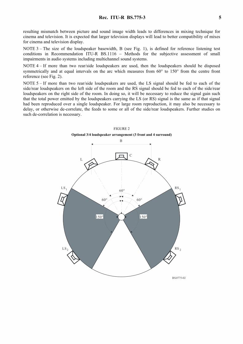
resulting mismatch between picture and sound image width leads to differences in mixing technique for cinema and television. It is expected that larger television displays will lead to better compatibility of mixes for cinema and television display. NOTE 3 – The size of the loudspeaker basewidth, B (see Fig. 1), is defined for reference listening test conditions in Recommendation ITU-R BS.1116 – Methods for the subjective assessment of small impairments in audio systems including multichannel sound systems. NOTE 4 – If more than two rear/side loudspeakers are used, then the loudspeakers should be disposed symmetrically and at equal intervals on the arc which measures from 60° to 150° from the centre front reference (see Fig. 2). NOTE 5 – If more than two rear/side loudspeakers are used, the LS signal should be fed to each of the side/rear loudspeakers on the left side of the room and the RS signal should be fed to each of the side/rear loudspeakers on the right side of the room. In doing so, it will be necessary to reduce the signal gain such that the total power emitted by the loudspeakers carrying the LS (or RS) signal is the same as if that signal had been reproduced over a single loudspeaker. For large room reproduction, it may also be necessary to delay, or otherwise de-correlate, the feeds to some or all of the side/rear loudspeakers. Further studies on such de-correlation is necessary.
FIGURE 2 Optional 3/4 loudspeaker arrangement (3 front and 4 surround)
BS.0775-02
150°
60°
LC
B
150°
60°
60°
R
LS1 RS 1
LS 2 RS 2
6 Rec. ITU-R BS.775-3
Annex 1
Hierarchy of compatible multichannel sound systems for broadcasting and recording
BS.0775-A1
RL
(MS) (MS)LS RS
(1) (1)
M
MSMS(1) (1)
RL
60°
(MS) (MS)LS RS
(1) (1)
C
M
System Channels Code Loudspeaker arrangement
Mono channel system
Mono plus mono surround
Two-channel stereo
Two-channel stereo plus 2 surround
Three-channel stereo plus 1 surrond
Three-channel stereo plus 2 surround
Two-channel stereo plus 1 surround
Three-channel stereo
M
M/MS
L/R
L/R/MS
L/R/LS/RS
L/C/R
L/C/R/MS
L/C/R/LS/RS
1/0
1/1
2/0
2/1
3/0
3/2
3/1
2/2
In the case of mono surround the signal feeding LS and RS should preferably be decorrelated.(1)
Rec. ITU-R BS.775-3 7
Annex 2
Basic requirements
The following requirements are related to the specified multichannel sound system with and without accompanying picture.
1 The directional stability of the frontal sound image shall be maintained within reasonable limits over a listening area larger than that provided by conventional two-channel stereophony.
2 The sensation of spatial reality (ambience) shall be significantly enhanced over that provided by conventional two-channel stereophony. This shall be achieved by the use of side and/or rear loudspeakers.
3 It is not required that the side/rear loudspeakers should be capable of the prescribed image locations outside the range of the front loudspeakers.
4 Downward compatibility with sound systems providing lower number of channels (down to stereophonic and monophonic sound systems) shall be maintained (see Annexes 1, 3, 4 and 8).
5 Real-time mixing for live broadcast shall be practicable.
6 In cases where the number of delivered signals is smaller than the number of reproduction channels upward conversion should be ensured to an acceptable degree (see Annex 5).
7 The basic audio quality of the sound reproduced after decoding shall be subjectively indistinguishable from the reference for most types of audio programme material. Using the triple stimuli with hidden reference test implies grades consistently higher than four on the ITU-R impairment 5-grade scale. The most critical material shall not be graded lower than four. For subjective assessments and listening test conditions see Recommendation ITU-R BS.1116.
8 For the objective quality parameters Recommendations ITU-R BS.644 and ITU-R BS.645 shall be the basis for digital techniques. For objective measurements method of perceived audio quality for mono or two-channel stereo sound see Recommendation ITU-R BS.1387. (The objective measurements method for multichannel stereophonic sound is under study by ITU-R.)
9 Relative timing of the synchronization of sound and vision signals see Recommendation ITU-R BT.1359.
10 Optimum economy shall be pursued in all respects, including both cost and transmission bandwidth.
11 For user requirements for audio coding systems for digital broadcasting see Recommendation ITU-R BS.1548.
8 Rec. ITU-R BS.775-3
Annex 3
Compatibility
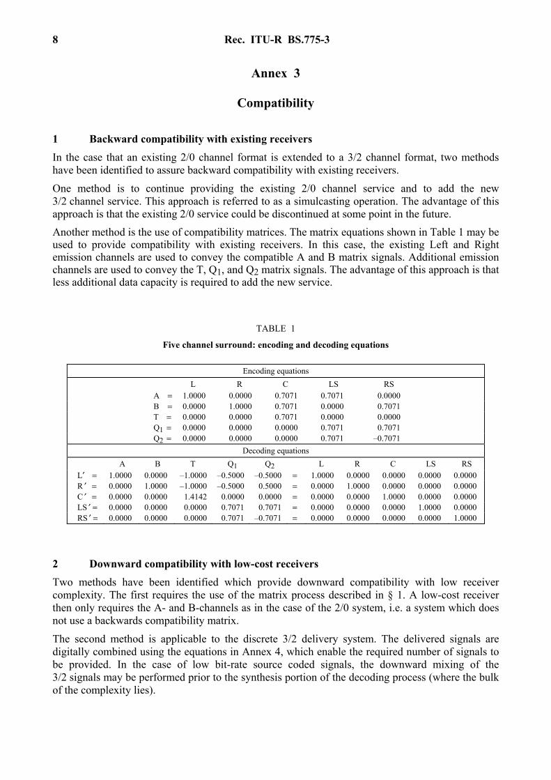
1 Backward compatibility with existing receivers In the case that an existing 2/0 channel format is extended to a 3/2 channel format, two methods have been identified to assure backward compatibility with existing receivers.
One method is to continue providing the existing 2/0 channel service and to add the new 3/2 channel service. This approach is referred to as a simulcasting operation. The advantage of this approach is that the existing 2/0 service could be discontinued at some point in the future. Another method is the use of compatibility matrices. The matrix equations shown in Table 1 may be used to provide compatibility with existing receivers. In this case, the existing Left and Right emission channels are used to convey the compatible A and B matrix signals. Additional emission channels are used to convey the T, Q1, and Q2 matrix signals. The advantage of this approach is that less additional data capacity is required to add the new service.
TABLE 1
Five channel surround: encoding and decoding equations
2 Downward compatibility with low-cost receivers
Two methods have been identified which provide downward compatibility with low receiver complexity. The first requires the use of the matrix process described in § 1. A low-cost receiver then only requires the A- and B-channels as in the case of the 2/0 system, i.e. a system which does not use a backwards compatibility matrix.
The second method is applicable to the discrete 3/2 delivery system. The delivered signals are digitally combined using the equations in Annex 4, which enable the required number of signals to be provided. In the case of low bit-rate source coded signals, the downward mixing of the 3/2 signals may be performed prior to the synthesis portion of the decoding process (where the bulk of the complexity lies).
Encoding equations L R C LS RS A = 1.0000 0.0000 0.7071 0.7071 –0.0000 B = 0.0000 1.0000 0.7071 0.0000 –0.7071 T = 0.0000 0.0000 0.7071 0.0000 –0.0000 Q1 = 0.0000 0.0000 0.0000 0.7071 –0.7071 Q2 = 0.0000 0.0000 0.0000 0.7071 –0.7071
Decoding equations A B T Q1 Q2 L R C LS RS L′ = 1.0000 0.0000 –1.0000 –0.5000 –0.5000 = 1.0000 0.0000 0.0000 0.0000 0.0000 R ′ = 0.0000 1.0000 –1.0000 –0.5000 00.5000 = 0.0000 1.0000 0.0000 0.0000 0.0000 C ′ = 0.0000 0.0000 01.4142 00.0000 00.0000 = 0.0000 0.0000 1.0000 0.0000 0.0000 LS ′ = 0.0000 0.0000 00.0000 00.7071 00.7071 = 0.0000 0.0000 0.0000 1.0000 0.0000 RS ′ = 0.0000 0.0000 00.0000 00.7071 –0.7071 = 0.0000 0.0000 0.0000 0.0000 1.0000

Rec. ITU-R BS.775-3 9
Annex 4
Downward mixing of multichannel audio signals
1 3/2 source signals Table 2 shows a set of equations that may be used to mix the five signals of the 3/2 system down to the formats: 1/0; 2/0; 3/0; 2/1; 3/1; 2/2.
TABLE 2
Downward mixing equations for 3/2 source material
It should be noted that the overall effect of such downward mixing equations (and compatibility matrixing, see Annex 3) will depend on other factors, such as the panning equations and microphone characteristics. It is recommended that further studies on such interactions be carried out (see Annex 8).
Mono – 1/0 format L R C LS RS
C ′ = 0.7071 0.7071 1.0000 0.5000 0.5000
Stereo – 2/0 format L R C LS RS
L′ = 1.0000 0.0000 0.7071 0.7071 0.0000
R ′ = 0.0000 1.0000 0.7071 0.0000 0.7071
Three channels – 3/0 format L R C LS RS
L ′ = 1.0000 0.0000 0.0000 0.7071 0.0000
R ′ = 0.0000 1.0000 0.0000 0.0000 0.7071
C ′ = 0.0000 0.0000 1.0000 0.0000 0.0000
Three channels – 2/1 format L R C LS RS
L′ = 1.0000 0.0000 0.7071 0.0000 0.0000
R ′ = 0.0000 1.0000 0.7071 0.0000 0.0000
S ′ = 0.0000 0.0000 0.0000 0.7071 0.7071
Four channels – 3/1 format L R C LS RS
L′ = 1.0000 0.0000 0.0000 0.0000 0.0000
R ′ = 0.0000 1.0000 0.0000 0.0000 0.0000
C ′ = 0.0000 0.0000 1.0000 0.0000 0.0000
S ′ = 0.0000 0.0000 0.0000 0.7071 0.7071
Four channels – 2/2 format L R C LS RS
L′ = 1.0000 0.0000 0.7071 0.0000 0.0000
R ′ = 0.0000 1.0000 0.7071 0.0000 0.0000
LS′ = 0.0000 0.0000 0.0000 1.0000 0.0000
RS ′ = 0.0000 0.0000 0.0000 0.0000 1.0000
10 Rec. ITU-R BS.775-3
Annex 5
Upwards conversion
Upwards conversion is needed in cases where the number of production channels is smaller than the number of channels available for reproduction. A typical example is a 2-channel stereo programme (2/0) that is to be presented over a 3/2 reproduction system.
Upwards conversion involves the generation of the “missing” channels somewhere in the broadcast chain. When performing upwards conversion, the following guidelines should normally be respected in order that the programme makers have a reference arrangement. These guidelines do not exclude the possibility, for receiver manufacturers, of the implementation of more sophisticated techniques.
1 Frontal channels 1.1 When a monophonic programme is to be presented over a reproduction system with three frontal loudspeakers, the mono signal should be presented over the centre loudspeaker only. When two frontal loudspeakers are only available, the mono signal should be presented over both left and right loudspeakers with an attenuation of 3 dB.
1.2 When a stereophonic programme is to be presented over a reproduction system with three frontal loudspeakers, the left and right signals of the stereo programme should be presented respectively over the left and right loudspeakers only.
2 Surround channels 2.1 When there is no surround signal in a programme, surround loudspeakers should not be activated.
2.2 When a given surround signal is to be reproduced over more than one loudspeaker, de-correlation between each loudspeaker signal should be performed. Furthermore, proper attenuation should be applied to each loudspeaker signal so that the combined sound pressure level produced by these loudspeakers should match that of a single frontal loudspeaker if fed by the same signal at a given reference listening position.
3 Data channel Auxiliary information describing the mode of transmission (number and type of transmitted channels) should be transmitted periodically in a special data channel in parallel with the programme. This information will be needed to perform upwards conversion in receivers.
Rec. ITU-R BS.775-3 11
Annex 6
Additional data*
It is necessary that some additional data are sent to the multichannel sound receiver, to enable it to identify the multichannel sound configuration in use, and provide the loudspeakers with the required signals. Implicit in the ability to reconfigure a multichannel sound system is the ability to use the available sound channels flexibly, so that a wide range of applications can be covered.
The details of the additional data (bit rate, data format, etc.) have yet to be determined. However, the following applications, which would need to be signalled in the data channel, have been identified: – the signalling and controlling of different multichannel sound configurations for the main
programme and conversion (e.g. 5-channel, 3-channel, 2-channel, mono) to other configurations;
– indicating a special sound signal for listeners with impaired hearing; – indicating a special sound signal for viewers with impaired sight; – indicating a separate audio programme (SAP); – conveying dynamic range control information, to compress or expand the dynamic range; – conveying characters for a text service; – flexible usage of the data capacity allocated for audio signals.
Annex 7
Low frequency effects channel (LFE)
The purpose of this optional channel is to enable delivery of higher levels of low frequency energy, that can be reproduced by those users that are equipped with sufficient low frequency reproduction capability to reproduce the high level low frequency effects. It was originally devised by the film industry for their digital sound systems.
In the film industry the LFE channel carries high level, low frequency sound effects which are intended to be fed to specific low frequency loudspeakers (subwoofers). In that way the magnitude of the low frequency content of the other channels is restricted so that the main loudspeakers are not required to handle these special effects signals. The main film sound channels carry normal low frequency sounds but not at such high levels. They are therefore sufficient on their own if these special effects are not required by the user. This combination has the other benefit that the coding of the high level signals in the LFE channel can be optimized without affecting the coding of the main channels. Subwoofer usage in the cinema is in contrast to domestic installations, where bass management is used to combine or to separate signals sent to the loudspeakers, which might, or might not, include a subwoofer.
* Further studies and contributions from administrations are necessary.
12 Rec. ITU-R BS.775-3
Although it is recognized that the number of domestic consumers who will choose to use a LFE channel is likely to be restricted, it is also recognized that there are other applications of the HDTV sound system that make more use of this option.
The LFE channel should not, however, be used for the entire low frequency content of the multichannel sound presentation. The LFE channel is an option, at the receiver, and thus should only carry the additional enhancement information. The LFE channel is often not included in a 2-channel downmix. The main channels must contain all the essential programme elements necessary for the audience.
(In a similar way, the surround channels should carry their own low frequency information rather than it being mixed into the front channels. This forward mixing of the low frequency sounds is an option, at the receiver, to decrease the requirements on the surround loudspeakers.)
The LFE channel should be capable of handling signals in the range 20-120 Hz.
Recommendation ITU-R BR.1384 specifies that the LFE channel is recorded with a level offset of –10 dB for the recording and exchange of multichannel sound programme material, and this offset is compensated for in the reproduction system. For broadcasting applications where signal levels are compliant with Recommendation ITU-R BR.1384, the level of LFE channel should be reproduced with positive offset gain of 10 dB relative to the main channels on reproduction. NOTE 1 – The film industry encodes the LFE channel such that a positive gain of 10 dB is required on reproduction and the reproduction level for DVD-Video is set to a positive gain of 10 dB relative to the main channels. However, the music industry, such as DVD-Audio or Super Audio CD, is currently coding the LFE channel such that zero offset gain is required on reproduction.
The coding of the main channels should not place any reliance on masking provided by the LFE channel. The coding of the LFE channel may, however, assume masking due to sounds reproduced from the main channels.
As most television programmes do not need to convey very high levels of low frequency energy, in general the LFE channel does not need to be employed. If the LFE channel is not used by a programme, then the programme will be reproduced correctly even if the reproduction system does not correctly reproduce the LFE channel.
Although LFE stands for “low frequency effects” in this Recommendation, in other standards it may be described as “low frequency enhancement”. Because of the design features of multi-channel audio systems, and the fact that the LFE channel is very often discarded by reproduction systems, it is better to think of it only as an enhancement – and definitely not as an essential component of the audio programme. The frequency responses of the listeners loudspeakers (and subwoofer if employed) are highly variable, especially at very low frequencies, and sometimes the consumer systems may be incorrectly configured. No attempt should be made to compensate for assumed characteristics of incorrectly configured domestic installations by using the LFE channel.
The LFE channel must therefore be considered as, at most, an enhancement, and definitely not as an essential part of the mix. If LFE use is thought advantageous in particular circumstances then it should only be used when there is a full understanding of the way the whole system of LFE, stereo down-mix, bass management, and subwoofers is intended to work (see Appendix).
The need for an LFE channel for domestic broadcasting is limited. The LFE channel in a “5.1” system is useful when the main channels are incapable of reproducing the desired amount of low frequency energy.
As many television and radio programmes do not need to use the LFE channel, for many programmes the LFE channel will be silent.
Rec. ITU-R BS.775-3 13
Appendix 1 to Annex 7 (informative)
Usage of the low frequency effects channel (LFE)
1 Introduction Digital compression systems currently used for the broadcast of surround sound for television include an extra audio channel specifically for the purpose of carrying high level, low frequency sound effects. This channel is the “.1” in “5.1” also called the LFE (low-frequency effects, or enhancement) channel.
There is often considerable misunderstanding about the use of the “.1” in surround sound, and how it relates to subwoofers. This Annex clarifies the differences between the two and describes some of the mistakes that can arise in audio systems as a result of incomplete understanding of their roles.
As most television programmes do not need to convey very high levels of low frequency energy, in general the LFE channel does not need to be employed. If the LFE channel is not used by a programme, then the programme will not be reproduced incorrectly if the reproduction system does not correctly reproduce the LFE channel.
Reference is made in this Annex to some specific audio coding systems that are commonly used for broadcast (« Dolby AC-3 », and « Dolby E »). These are cited simply as examples, and their mention here does not imply a recommendation or endorsement of their use.
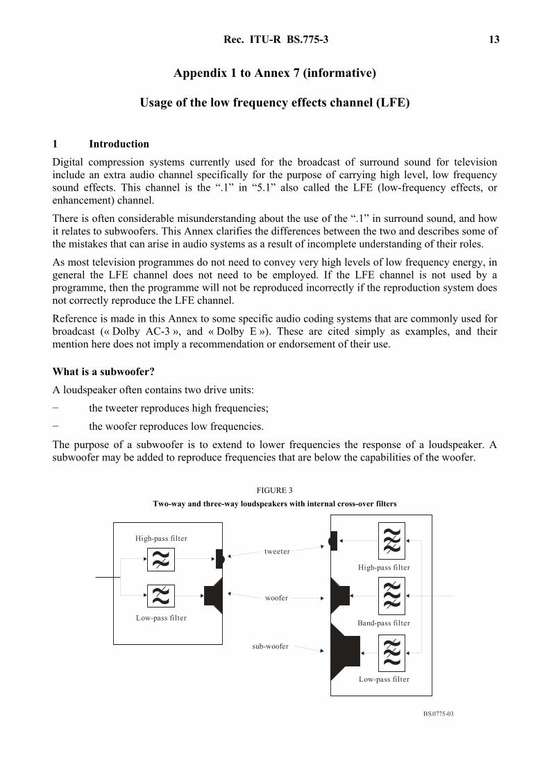
What is a subwoofer? A loudspeaker often contains two drive units:
− the tweeter reproduces high frequencies;
− the woofer reproduces low frequencies.
The purpose of a subwoofer is to extend to lower frequencies the response of a loudspeaker. A subwoofer may be added to reproduce frequencies that are below the capabilities of the woofer.
FIGURE 3 Two-way and three-way loudspeakers with internal cross-over filters
BS.0775-03
High-pass filter
Low-pass filter
tweeter
woofer
sub-woofer
High-pass filter
Low-pass filter
Band-pass filter

14 Rec. ITU-R BS.775-3
Because low frequencies are less directional than high frequencies, it is practicable to use a single, separate, subwoofer for a multi-loudspeaker set. There is now a wide selection of loudspeaker systems on the market where the main loudspeakers are rather small, with limited low-frequency output, and so the overall performance is dependent on the inclusion, in the system, of a separate subwoofer unit.
What is the LFE? The low frequency effects channel is most commonly encountered in Dolby AC-3 as the “.1” in “5.1”, although it is also present in some other audio systems. The purpose of the Dolby AC-3 low-frequency effects channel, (the LFE, or “0.1”), is to provide a channel for loud effects that would otherwise overload a normal channel. There are two characteristics of the LFE that suit this use: it has a limited bandwidth, of only 120 Hz, and it has 10 dB of gain applied on reproduction. The five normal channels in Dolby AC-3 are full band-width (from DC to half sampling rate); the LFE is a fractional bandwidth channel that encodes only a limited range of frequencies.
Although LFE stands for “low frequency effects” in this Recommendation, in other standards it may be described as “low frequency enhancement”. Because of the design features of multi-channel audio systems, and the fact that the LFE channel is very often discarded by reproduction systems, it is better to think of it only as an enhancement – and definitely not as an essential component of the audio programme.
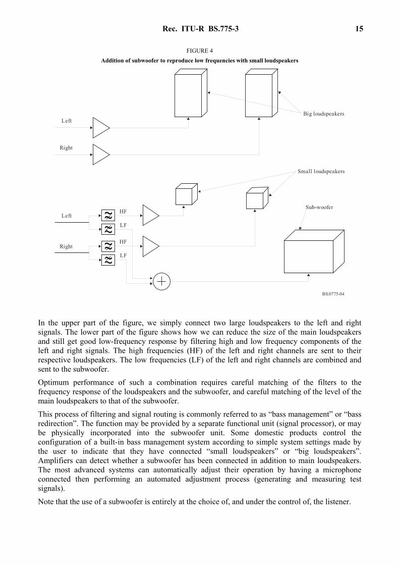
2 Using a subwoofer to extend frequency range Because basic physics limits the low-frequency performance of loudspeakers – the bigger, the better – it is useful to be able to use a single big loudspeaker to reproduce low frequencies, in combination with several smaller loudspeakers to reproduce higher frequencies (where there is spatial information). Figure 2 shows the steps required to add a subwoofer. Two channels are shown, to reduce the complexity of the drawing, but the same principle applies to more channels.
Rec. ITU-R BS.775-3 15
FIGURE 4 Addition of subwoofer to reproduce low frequencies with small loudspeakers
BS.0775-04
Left
Right
Big loudspeakers
Small loudspeakers
Sub-wooferLeft
Right
HF
LF
HF
LF
In the upper part of the figure, we simply connect two large loudspeakers to the left and right signals. The lower part of the figure shows how we can reduce the size of the main loudspeakers and still get good low-frequency response by filtering high and low frequency components of the left and right signals. The high frequencies (HF) of the left and right channels are sent to their respective loudspeakers. The low frequencies (LF) of the left and right channels are combined and sent to the subwoofer.
Optimum performance of such a combination requires careful matching of the filters to the frequency response of the loudspeakers and the subwoofer, and careful matching of the level of the main loudspeakers to that of the subwoofer.
This process of filtering and signal routing is commonly referred to as “bass management” or “bass redirection”. The function may be provided by a separate functional unit (signal processor), or may be physically incorporated into the subwoofer unit. Some domestic products control the configuration of a built-in bass management system according to simple system settings made by the user to indicate that they have connected “small loudspeakers” or “big loudspeakers”. Amplifiers can detect whether a subwoofer has been connected in addition to main loudspeakers. The most advanced systems can automatically adjust their operation by having a microphone connected then performing an automated adjustment process (generating and measuring test signals).
Note that the use of a subwoofer is entirely at the choice of, and under the control of, the listener.
16 Rec. ITU-R BS.775-3
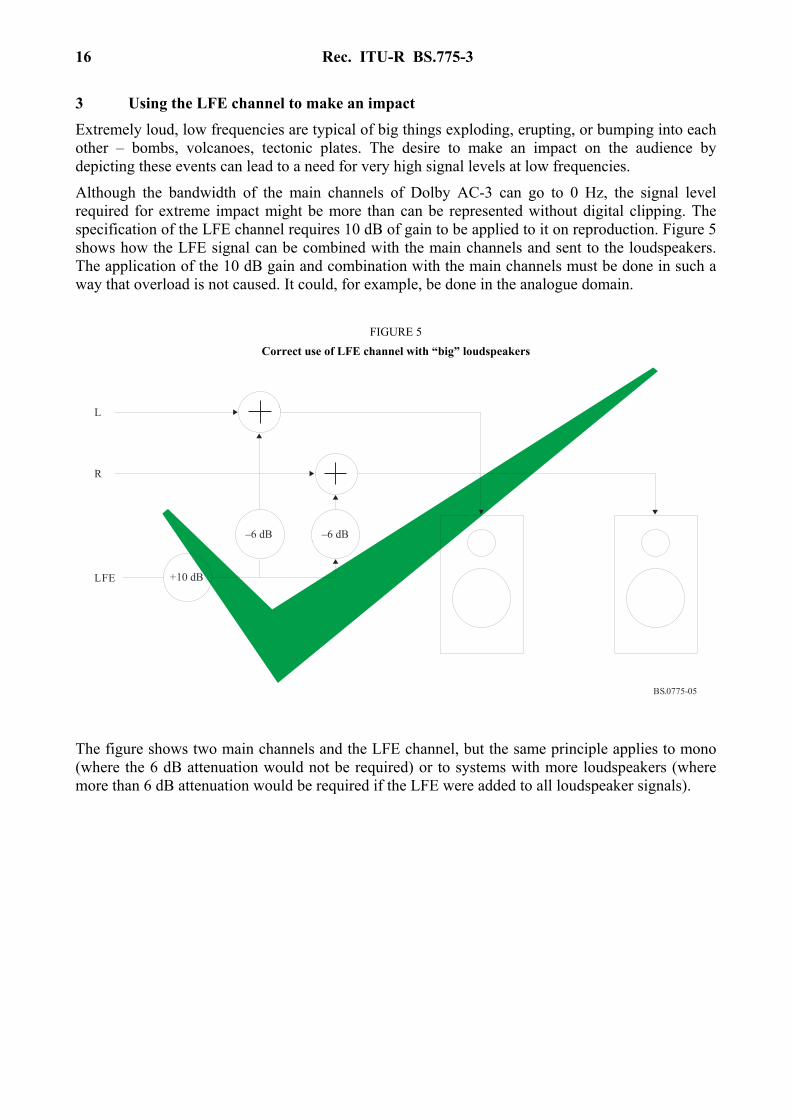
3 Using the LFE channel to make an impact Extremely loud, low frequencies are typical of big things exploding, erupting, or bumping into each other – bombs, volcanoes, tectonic plates. The desire to make an impact on the audience by depicting these events can lead to a need for very high signal levels at low frequencies.
Although the bandwidth of the main channels of Dolby AC-3 can go to 0 Hz, the signal level required for extreme impact might be more than can be represented without digital clipping. The specification of the LFE channel requires 10 dB of gain to be applied to it on reproduction. Figure 5 shows how the LFE signal can be combined with the main channels and sent to the loudspeakers. The application of the 10 dB gain and combination with the main channels must be done in such a way that overload is not caused. It could, for example, be done in the analogue domain.
FIGURE 5 Correct use of LFE channel with “big” loudspeakers
BS.0775-05
L
R
–6 dB–6 dB
LFE +10 dB
The figure shows two main channels and the LFE channel, but the same principle applies to mono (where the 6 dB attenuation would not be required) or to systems with more loudspeakers (where more than 6 dB attenuation would be required if the LFE were added to all loudspeaker signals).
Rec. ITU-R BS.775-3 17
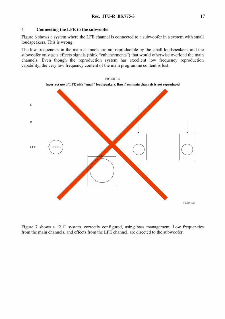
4 Connecting the LFE to the subwoofer Figure 6 shows a system where the LFE channel is connected to a subwoofer in a system with small loudspeakers. This is wrong.
The low frequencies in the main channels are not reproducible by the small loudspeakers, and the subwoofer only gets effects signals (think “enhancements”) that would otherwise overload the main channels. Even though the reproduction system has excellent low frequency reproduction capability, the very low frequency content of the main programme content is lost.
FIGURE 6 Incorrect use of LFE with “small” loudspeakers. Bass from main channels is not reproduced
BS.0775-06
L
R
LFE +10 dB
Figure 7 shows a “2.1” system, correctly configured, using bass management. Low frequencies from the main channels, and effects from the LFE channel, are directed to the subwoofer.

18 Rec. ITU-R BS.775-3
FIGURE 7 Correct use of LFE and bass management with “small” loudspeakers
BS.0775-07
L
R
LFE +10 dB
This looks rather more complex than the simple way of doing it wrong (as in Fig. 6).
A broadcaster might be tempted to pre-process its transmissions to take account of incorrect configuration in the home. Although it is commonly taught that “two wrongs do not make a right”, there is a way of trying that with an LFE channel and a subwoofer. Figure 8 shows signals from the main channels being put into the LFE signal before transmission, on the assumption that they will be reproduced by the subwoofer in the home.
FIGURE 8 Bass “mismanagement” before transmission to compensate for incorrect
configuration in the home (only two channels shown)
BS.0775-08
L
RLFE +10 dB
Transmission
–10 dB
L
R

Rec. ITU-R BS.775-3 19
This misuse of bass management, the LFE channel, and subwoofer is further complicated by the question of frequency responses. Figure 8, although “wrong”, could work for some people, but it depends on correct matching of frequency responses. If the cross-over frequency of the band-splitting filters in transmission do not match the responses of the subwoofer and main loudspeakers, there will be a hole, either because content that was too low in frequency to be reproduced by the main loudspeakers was not put in the LFE, or content that was put in the LFE was of too high a frequency to be reproduced by it.
No assumptions can be made about the frequency responses of the loudspeakers and subwoofer, since that depends entirely on the designer and manufacturer.
As well as misusing the LFE channel, this does not take into account one of the facts of life in surround sound broadcasting: most of the audience does not listen to surround sound, and this brings us to the subject of “down-mixing”.
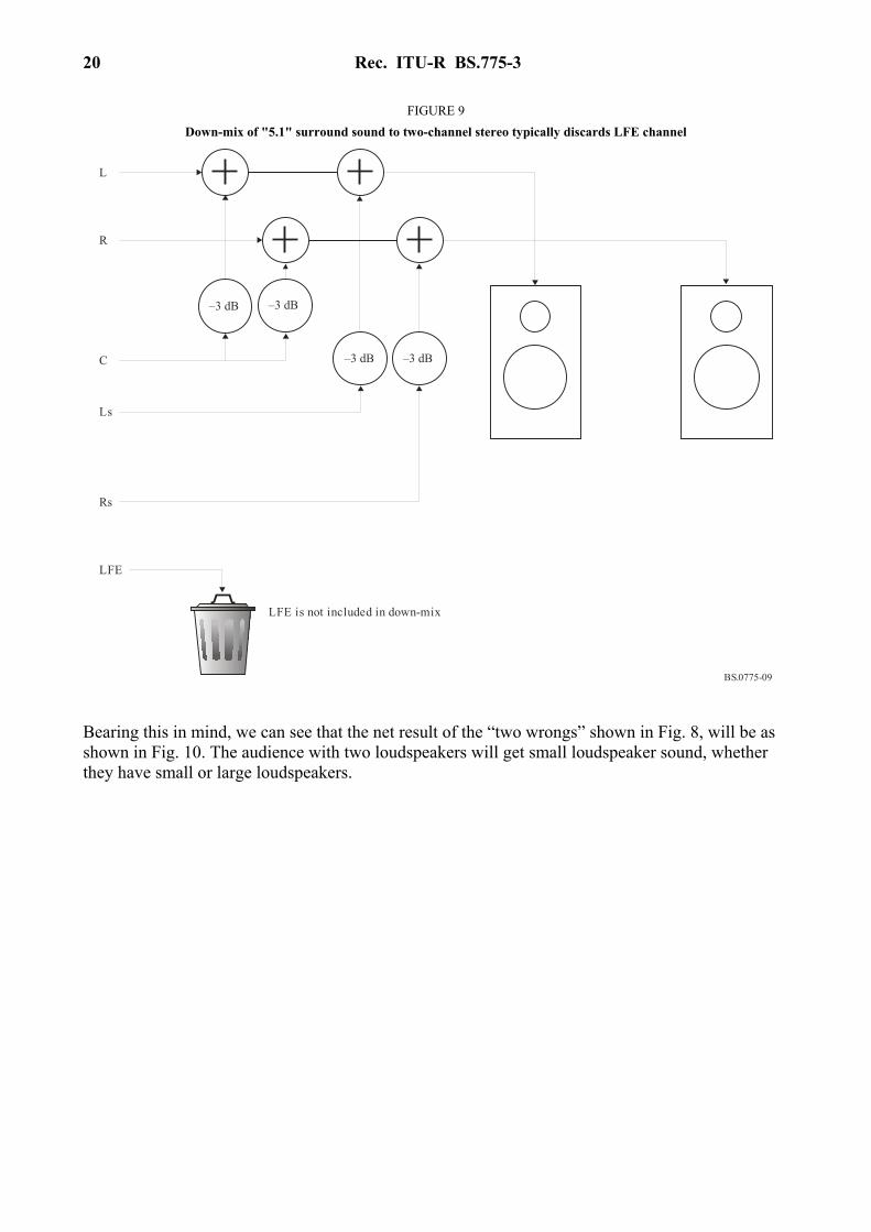
5 Down-mix of broadcast surround sound Even when listening to broadcasts transmitted in surround sound much of the audience continues to use only two loudspeakers, whether for cost reasons, or practicalities of installation. These listeners hear a down-mix, where the centre channel and surround channels are mixed into the front left and front right channels (to an extent controlled by metadata in the broadcast audio stream). Figure 9 shows how this is done in the receiver. The attenuations shown as 3 dB are just examples, and the actual values are under the control of the broadcaster, sent as metadata in the audio stream. Typically, the LFE channel is not included in the down-mix. (If it were included, it would likely overload the small stereo speakers that are used by the majority of the TV audience.)
20 Rec. ITU-R BS.775-3
FIGURE 9 Down-mix of "5.1" surround sound to two-channel stereo typically discards LFE channel
BS.0775-09
L
R
–3 dB–3 dB
Ls
–3 dB–3 dBC
Rs
LFE
LFE is not included in down-mix
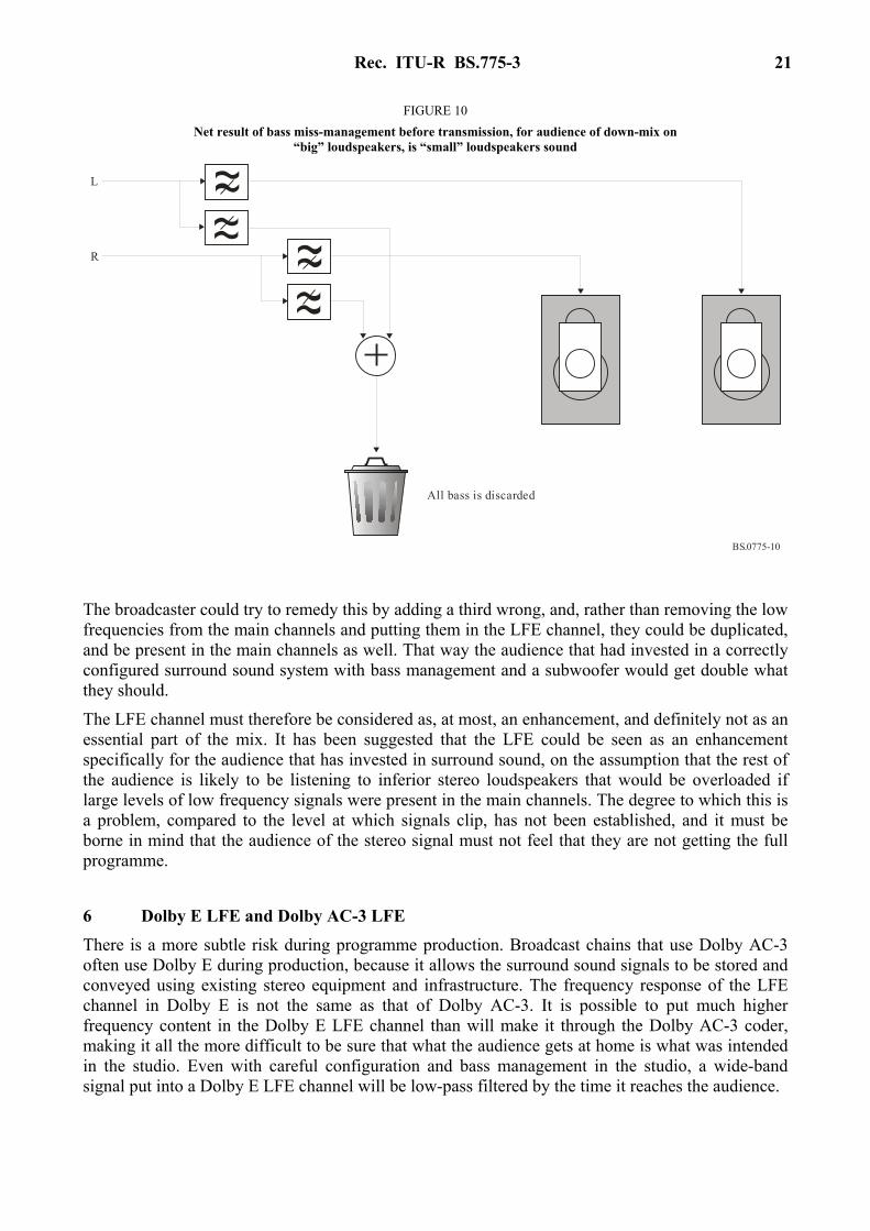
Bearing this in mind, we can see that the net result of the “two wrongs” shown in Fig. 8, will be as shown in Fig. 10. The audience with two loudspeakers will get small loudspeaker sound, whether they have small or large loudspeakers.
Rec. ITU-R BS.775-3 21
FIGURE 10 Net result of bass miss-management before transmission, for audience of down-mix on
“big” loudspeakers, is “small” loudspeakers sound
BS.0775-10
L
R
All bass is discarded
The broadcaster could try to remedy this by adding a third wrong, and, rather than removing the low frequencies from the main channels and putting them in the LFE channel, they could be duplicated, and be present in the main channels as well. That way the audience that had invested in a correctly configured surround sound system with bass management and a subwoofer would get double what they should.
The LFE channel must therefore be considered as, at most, an enhancement, and definitely not as an essential part of the mix. It has been suggested that the LFE could be seen as an enhancement specifically for the audience that has invested in surround sound, on the assumption that the rest of the audience is likely to be listening to inferior stereo loudspeakers that would be overloaded if large levels of low frequency signals were present in the main channels. The degree to which this is a problem, compared to the level at which signals clip, has not been established, and it must be borne in mind that the audience of the stereo signal must not feel that they are not getting the full programme.
6 Dolby E LFE and Dolby AC-3 LFE There is a more subtle risk during programme production. Broadcast chains that use Dolby AC-3 often use Dolby E during production, because it allows the surround sound signals to be stored and conveyed using existing stereo equipment and infrastructure. The frequency response of the LFE channel in Dolby E is not the same as that of Dolby AC-3. It is possible to put much higher frequency content in the Dolby E LFE channel than will make it through the Dolby AC-3 coder, making it all the more difficult to be sure that what the audience gets at home is what was intended in the studio. Even with careful configuration and bass management in the studio, a wide-band signal put into a Dolby E LFE channel will be low-pass filtered by the time it reaches the audience.
22 Rec. ITU-R BS.775-3
The transition from using Dolby E to using linear PCM (where the channel used for LFE will be full bandwidth) means that the scope for incompatible LFE channel signals to be produced is even greater.
7 Technical requirements The LFE channel should be capable of handling signals in the range 20-120 Hz.
Recommendation ITU-R BR.1384 specifies that the LFE channel is recorded with a level offset of –10 dB for the recording and exchange of multichannel sound programme material, and this offset is compensated for in the reproduction system. The level of LFE channel should be reproduced with positive offset gain of 10 dB relative to the main channels on reproduction.
NOTE 1 – The film industry encodes the LFE channel such that a positive gain of 10 dB is required on reproduction and the reproduction level for DVD-Video is set to a positive gain of 10 dB relative to the main channels. However, in the music industry, some formats such as DVD-Audio or Super Audio CD, is currently coding the LFE channel such that zero offset gain is required on reproduction; this usage of the LFE channel is not compliant with this Recommendation.
The coding of the main channels should not place any reliance on masking provided by the LFE channel. The coding of the LFE channel may, however, assume masking due to sounds reproduced from the main channels.
In broadcasting, the purpose of this optional channel is to enable listeners, who choose to, to extend the low frequency content of the reproduced programme in terms of both frequency and level. It was originally devised by the film industry for their digital sound systems. It does not generally extend any lower in frequency response than the main channels. The need for an LFE channel for domestic broadcasting is therefore limited. The LFE channel in a “5.1” system need only be active when all of the main 5 channels reach clipping.
In the film industry the LFE channel carries high level, low frequency sound effects which are intended to be fed to specific low frequency loudspeakers (subwoofers). This is in contrast to domestic installations, where bass management is used to combine or to separate signals sent to the loudspeakers, which might, or might not, include a subwoofer.
A subwoofer is a valuable addition to loudspeaker systems with limited bass response, as long as bass management is properly configured. It should be understood that it is not related in any way to the LFE channel. The subwoofer is connected to a bass management system, not to the LFE channel. The bass from the main channels may be added to the LFE signal, and the combination then fed to a subwoofer, or the LFE signal may be added to the main channels and the combination fed to the main loudspeakers. Direct connection of the LFE to the subwoofer relies on the assumption that the frequency responses (and overall gain) of all loudspeakers, all subwoofers, and all bass management systems are designed to interoperate. This assumption is clearly incorrect. Although it is recognized that the number of domestic consumers who will choose to use a LFE channel is likely to be restricted, it is also recognized that there are other applications of the HDTV sound system that make more use of this option.
Operational and configuration problems can possibly arise from the use of the LFE channel. These are compounded by the use of subwoofers when there are misunderstandings of the role of both. No attempt should be made to compensate for assumed characteristics of incorrectly configured domestic installations by using the LFE channel.
Further complication arises from the wide-spread use of stereo down-mixing in preference to surround sound loudspeaker systems. All content of the LFE channel is simply discarded in this situation. The main channels must contain all the essential programme elements necessary for the audience.
Rec. ITU-R BS.775-3 23
The LFE channel must not be used for the entire low frequency content of the multichannel sound presentation. The LFE channel is an option, at the receiver, and thus should only carry the additional enhancement information.
(In a similar way, the surround channels should carry their own low frequency information rather than it being mixed into the front channels. This forward mixing of the low frequency sounds is an option, at the receiver, to decrease the requirements on the surround loudspeakers.)
Most television and radio programmes do not need to use the LFE channel. Thus for many programmes the LFE channel will be silent. If LFE use is thought advantageous in particular circumstances then it should only be used when there is a full understanding of the way the whole system of LFE, stereo down-mix, bass management, and subwoofers is intended to work.
Manufacturers of audio and television receivers are hereby encouraged to provide their customers with clear instructions on the proper configuration of their audio system, in order that consumers may fully enjoy the benefits of the “5.1” audio format, when available in broadcast programmes.
Where feasible, consumers should be made aware that, where their audio system includes a subwoofer, the connection to the subwoofer should be made through a properly configured bass management system.
Annex 8
Compatibility matrixing and downward mixing
Methods for providing backward compatibility and downward compatibility are described in Annex 3. Annex 4 contains downward mixing equations for 3/2 source material.
However, it is recognized that the alternative down-mix coefficients for the surround signals LS/RS are desirable, depending on the type of the programme material.
Four alternative surround signal down-mix coefficients should be indicated by the broadcaster.
0.7071
0.5000
0.0000
Reserved
Additional data should be transmitted to indicate which coefficient should be used.


![Development of A Steerable Stereophonic Parametric Loudspeaker · Development of A Steerable Stereophonic Parametric Loudspeaker Chuang Shi , ... [13]. Therefore, the ... When the](https://img.pdfslide.us/doc/110x75/5aef235b7f8b9aa9168c2768/development-of-a-steerable-stereophonic-parametric-of-a-steerable-stereophonic-parametric.jpg)