Embed Size (px)
Citation preview
Multicast
Henning Schulzrinne
Dept. of Computer Science
Columbia University
Fall 2003
Overview
IP multicast service models– any source, source-specific multicast, …
Multicast protocol components– address assignment– local group management– intra- and inter-domain routing
Programming IP multicast applications
Multicast service models
Basic idea: same data needs to reach multiple receivers avoid transmitting it once for each receiver
– particularly useful if access link has bandwidth limitations– can be implemented at link, network and application layer– e.g., mailing list as example
Variations: reach unknown destination by membership (“foo server”) rather than address also anycast
*Cast
Broadcast = all nodes on (small, local) network
Directed broadcast = copies to all hosts on remote network– DDOS not supported any more (RFC 2644)
Multicast = copies to >= 1 hosts (group) Anycast = packet to 1 of N hosts

Diversion: Anycast
RFC 1546 (“Host Anycasting Service”)– RFC 2373 (“IP Version 6 Addressing Architecture”)
“locate a host which supports a particular service but, if several servers support the service, does not particularly care which server is used.”
Example uses:– DNS root servers (F.root-servers.net = 192.5.5.241 ); see http://www.isc.org
root servers are hard-configured in DNS resolvers 272 million queries a day
– all access routers providing Internet service Anycast deliver to single host
– special form of unicast routing– deliver to nearest host (by routing metric)
Multicast deliver to >= 1 host (and maybe get answers from > 1 host)
Anycast routing
Assign same address within subnet– supernet is advertised either globally (“global nodes”) or
locally (“local nodes”)– advertise whole prefix, not just single address avoid
route filtering BGP automatically ensures routing to closest local or
global node Distributes (or localizes) denial-of-service traffic Does not scale well due to address usage (unless all
services within the same subnet)

Multicast applications
audio-video distribution (1-to-many) audio-video conferences (all-to-all) distributed simulation (war gaming, multi-player
Doom, …) resource discovery (where’s the next time server?)
– instances of resource identified by multicast address file distribution (stock market quotes, new software
releases, OS patches, …) network news (Usenet)
Multicast trees
spanning tree ≡ tree that connects all vertices– vertices = hosts and routers
shared tree = single tree for all sources S– minimum cost spanning tree (MST)
minimum-weight tree in a weighted graph which contains all of the graph's vertices
cost = hops, delay, transmission cost ($), …– does not minimize length of S to individual destination– all traffic concentrated on tree reservation failure
per-source tree– build independently for each source

Multicast trees – Steiner trees
“given a weighted graph in which a subset of vertices are identified as terminals, find a minimum-weight connected subgraph that includes all the terminals”
Differs from MST in that Steiner vertices must be identified
NP-complete problem (see traveling salesman)– unstable: small additions to graph large changes in traffic
flows

Finding MST via Prim’s algorithm
centralized, finds MST for G = (V,E) U: set of vertices connected, start with one add lowest-cost edge (u,v) with u U and v
in V – U tree T T (u,v) U U v

Connection-oriented multicast
enumerate sources explicitly source-based tree examples:
– ATM: explicitly add each end point to tree– ST-II (IPv5): enumerate end points in setup message– End nodes can also attach themselves to tree
only connection-oriented enumeration only in setup message
source needs to know destinations– resource discovery not possible– dynamic groups difficult
but: natural transition from 2-party to N-party– same routing algorithm

Host group model
Multicast service model S. Deering, 1991 (RFC 1112)
– senders need not be members– groups may have any number of members– there are no topological restrictions on group membership– membership is dynamic and autonomous– host groups may be dynamic or permanent
receiver-driven model– “subscriptions”

Local multicast
Some local networks are by (original) nature multicast or broadcast:
– Ethernet: original coax contention (CDMA), 802.11 wireless need to emulate in Ethernet switches
– token ring– FDDI– wireless links (BlueTooth, cellular), powerline networks
Ethernet, token ring:– broadcast: all-1 address– multicast: 01.xx.xx.xx.xx.xx– adapter hardware can filter dynamic list of addresses
ATM: point-to-point links ATM multicast server or replication in switches
IP multicast: model & addresses
host-group model network level: data packets remain same, only address changes need help from routers to replicate and route special IP addresses (class D): 224.0.0.0 through 239.255.255.255 (224/4)
– 28 bits 268 million groups– in addition, scoping
224.0.0.x: local network only– 224.0.0.1: all hosts– 224.0.0.2: all routers
224.0.1.x: internetwork control block 224.0.2.0-224.0.255.0: ad-hoc 224.2.0.0-224.2.255.255: SDP/SAP block some pre-assigned by IANA map into Ethernet: 01.00.5E.00.00.00 + lower 23 bits
IP multicast scope
Avoid accidental distribution to whole Internet IP TTL value: 0 = host, 1 = network Others to reach larger groups
– but “split horizon problem” (RFC 2907)– pruning (see later) may fail: larger TTL later
Administrative scoping (RFC 2365)– 239.0.0.0 to 239.255.255.255– RFC 1884 for IPv6 (16 scopes)– link-local scope– IPv4 local scope– organization local scope– global scope
relative addresses (from top) for common applications within scope
IP multicast protocols
tree construction protocol PIM-SM, PIM-DM advertise reverse paths towards sources
Multiprotocol Border Gateway Protocol (MBGP) disseminate information about sources Multicast
Source Discovery Protocol (MSDP) hosts dynamically join and leave multicast groups
Internet Group Management Protocol (IGMP)– IGMPv2: specify host group
Multicast model problems
Host group model now known as Any Source Multicast (ASM)– variant: source-filtered multicast (SFM)– hosts can request data for group G only for specific set of sources– or exclude list of sources IGMPv3 for IPv4 and MLD (listener discovery) for IPv6
host of problems have prevented large-scale deployment:– attacks against multicast groups by unauthorized transmitters– deployment complexity– problems of allocating scarce global class-D IP addresses– lack of inter-domain scalability– single point-of-failure problems
K. Almeroth, S. Bhattacharyya, C. Diot, “Challenges of Integrating ASM and SSMIP Multicast Protocol Architectures”
Source-Specific Multicast (SSM)
receiving host explicitly specifies the address of the source it wants to receive from– in addition to multicast group
support one-to-many multicast address range 232/8, ff2x:: and ff3x:: IGMPv3: allow source specification remove complexity from network layer
application layer (where needed)
SSM, cont’d.
distribution tree for channel (S,G) rooted at S– no shared tree infrastructure
no need for MSDP only a single source can transmit
– avoid access control problem– avoid forwarding unwanted data (cf. SFM)– addresses local to each source no global address
allocation needed for large groups, often single source
– or dominated by single source
Xcast
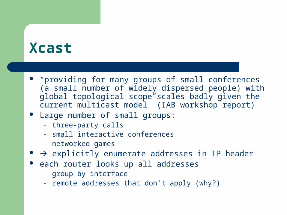
“providing for many groups of small conferences (a small number of widely dispersed people) with global topological scope scales badly given the current multicast model” (IAB workshop report)
Large number of small groups:– three-party calls– small interactive conferences– networked games
explicitly enumerate addresses in IP header each router looks up all addresses
– group by interface– remote addresses that don’t apply (why?)
Xcast
Thus, sender-driven model Advantages:
– no session setup needed– no address allocation– known set of destinations: simplifies accounting,
access control
RPF – Reverse path forwarding
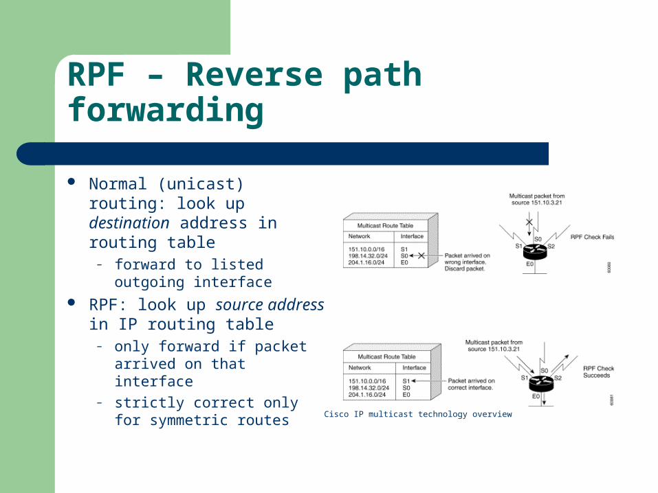
Normal (unicast) routing: look up destination address in routing table
– forward to listed outgoing interface
RPF: look up source address in IP routing table
– only forward if packet arrived on that interface
– strictly correct only for symmetric routes Cisco IP multicast technology overview

PIM-DM
Uses unicast routing protocols (unlike DVMRP)
push model send traffic everywhere non-receivers prune time out after 3 minutes only source trees good for networks where most subnets want
traffic

PIM-SM
pull model join only (G,*) initially, shared tree =
rendezvous point (RP) router closest to receiver
registers with RP sources register with RP and
then initially send data via the shared tree
edge routers can force a source tree by sending (S,G) messages towards the source if distance to source is smaller than distance to RP
see draft-ietf-pim-v2-dmCisco IP multicast technology overview
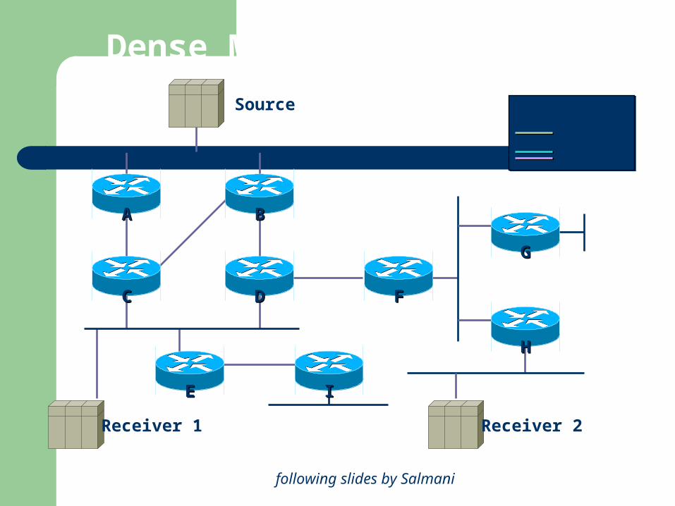
Dense Mode PIM Example
Source
Receiver 2Receiver 1
DD FF
II
BB
CC
AA
EE
GG
HH
Link
Data
Control
following slides by Salmani
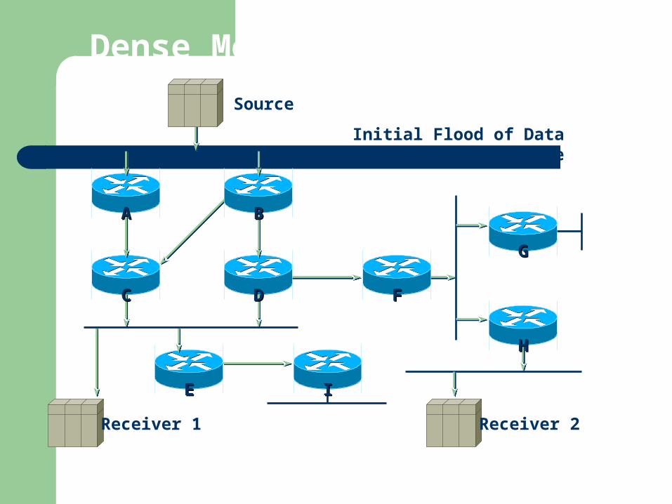
Dense Mode PIM Example
Initial Flood of Dataand Creation of State
Source
Receiver 2Receiver 1
DD FF
II
BB
CC
AA
EE
GG
HH

Dense Mode PIM Example
Prune to Non-RPF Neighbor
Source
Prune
Receiver 2Receiver 1
DD FF
II
BB
CC
AA
EE
GG
HH

Dense Mode PIM Example
C and D Assert to DetermineForwarder for the LAN, C Wins
Source
Asserts
Receiver 2Receiver 1
DD FF
II
BB
CC
AA
EE
GG
HH
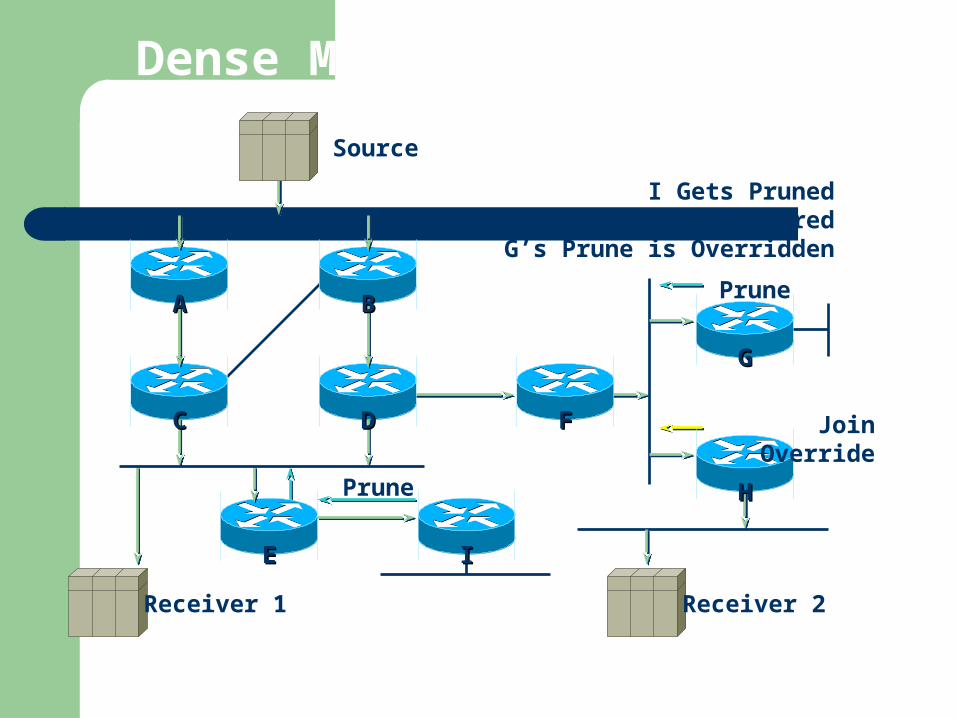
Dense Mode PIM Example
I Gets PrunedE’s Prune is Ignored
G’s Prune is Overridden
Source
Prune
Receiver 2Receiver 1
Join Override
Prune
DD FF
II
BB
CC
AA
EE
GG
HH
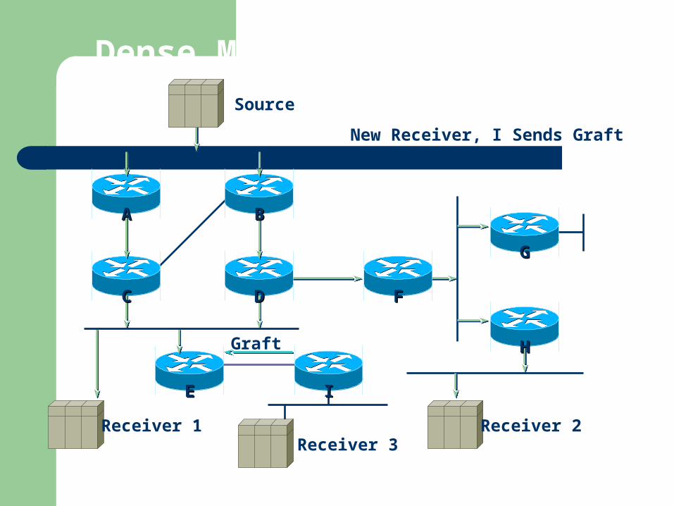
Dense Mode PIM ExampleSource
Graft
Receiver 2Receiver 3
Receiver 1
New Receiver, I Sends Graft
DD FF
II
BB
CC
AA
EE
GG
HH
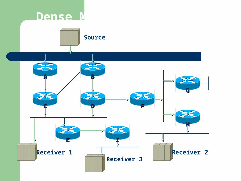
Dense Mode PIM Example
Source
Receiver 2Receiver 3
Receiver 1
DD FF
II
BB
CC
AA
EE
GG
HH
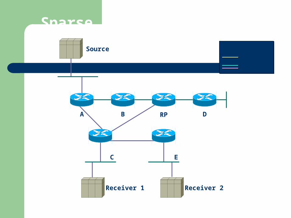
Sparse Mode PIM Example
Receiver 1
B
E
A D
Source
C
Receiver 2
RP
Link
Data
Control
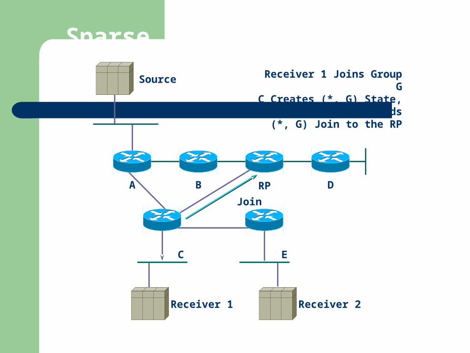
Sparse Mode PIM Example
Receiver 1
B
E
A D
Source Receiver 1 Joins Group GC Creates (*, G) State, Sends
(*, G) Join to the RP
C
Receiver 2
RP
Join
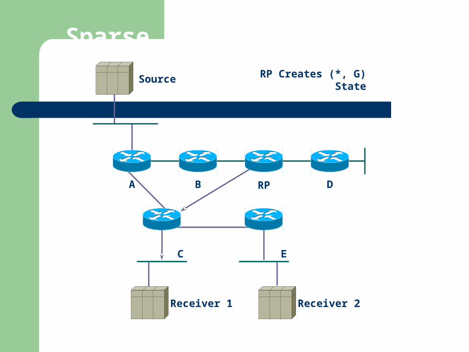
Sparse Mode PIM Example
Receiver 1
B
E
A RP D
Source RP Creates (*, G) State
C
Receiver 2
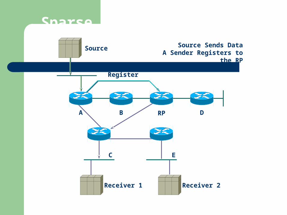
Sparse Mode PIM Example
Receiver 1
B
E
A RP D
Source Source Sends DataA Sender Registers to the
RP
C
Receiver 2
Register
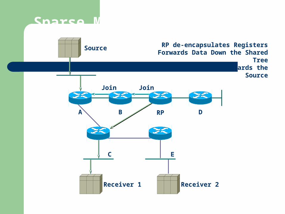
Sparse Mode PIM Example
Receiver 1
B
E
A RP D
Source RP de-encapsulates RegistersForwards Data Down the Shared Tree
Sends Joins Towards the Source
C
Receiver 2
Join Join

Sparse Mode PIM Example
Receiver 1
B
E
A RP D
Source RP Sends Register-Stop Once
Data Arrives Natively
C
Receiver 2
Register-Stop

Sparse Mode PIM Example
Receiver 1
B
E
A RP D
Source C Sends (S, G) Joins to Join the
Shortest Path (SPT) Tree
C
Receiver 2
(S, G )Join
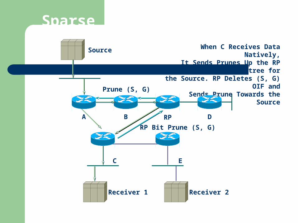
Sparse Mode PIM Example
Receiver 1
B
E
A RP D
Source When C Receives Data Natively,It Sends Prunes Up the RP tree for
the Source. RP Deletes (S, G) OIF andSends Prune Towards the Source
C
Receiver 2
(S, G )RP Bit Prune
(S, G )Prune
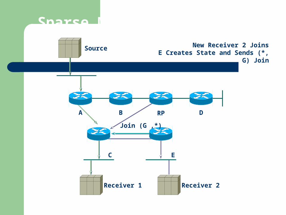
Sparse Mode PIM Example
Receiver 1
B
E
A RP D
Source New Receiver 2 JoinsE Creates State and Sends (*, G) Join
C
Receiver 2
,*(G )Join

Sparse Mode PIM Example
Receiver 1
B
E
A RP D
Source C Adds Link Towards E to the OIFList of Both (*, G) and (S, G)
Data from Source Arrives at E
C
Receiver 2
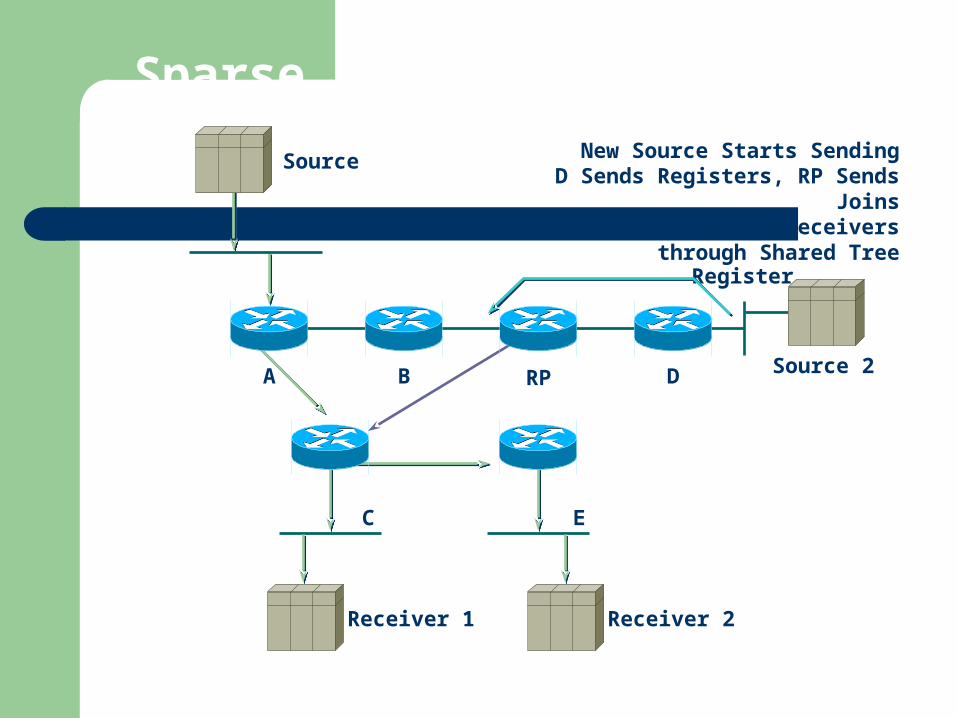
Sparse Mode PIM Example
Receiver 1
B
E
A RP D
Source New Source Starts SendingD Sends Registers, RP Sends Joins
RP Forwards Data to Receiversthrough Shared Tree
C
Receiver 2
Source 2
Register
MBGP (Multiprotocol BGP)
RFC 2283 (Multiprotocol Extensions for BGP-4)
RPF check for AS path attributes MP_REACH_NLRI and
MP_UNREACH_NLRI two sets of routing information non-congruent unicast and multicast topologies
MSDP (Multicast source discovery protocol)
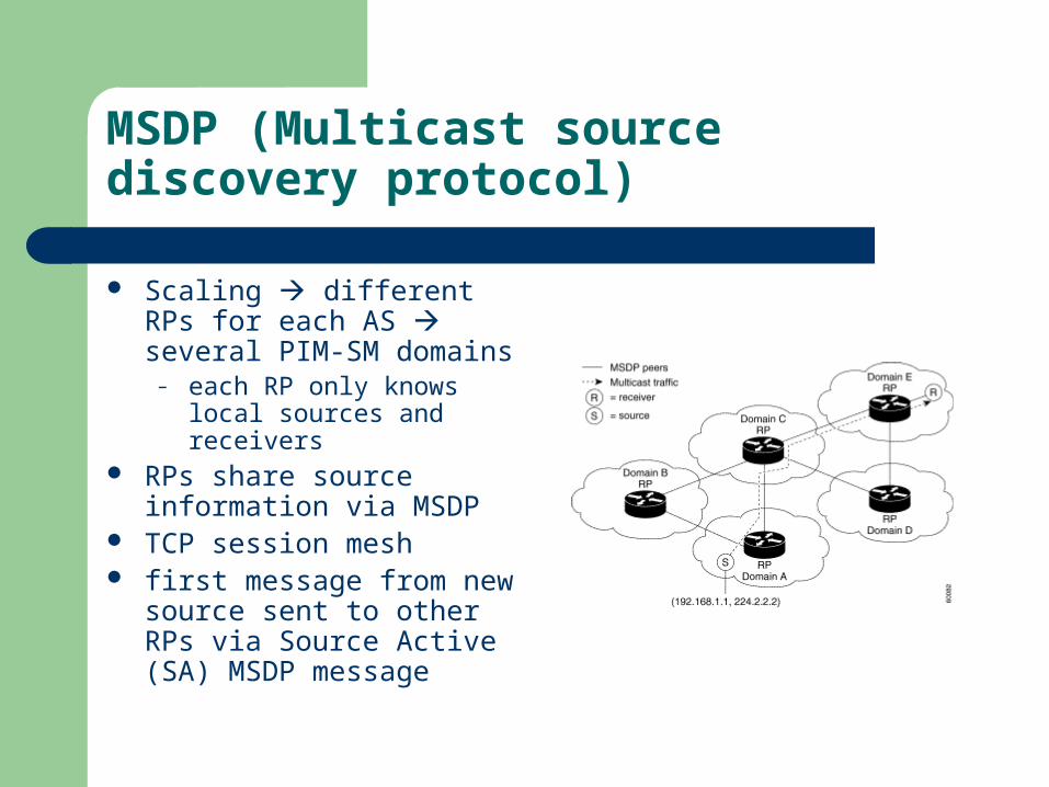
Scaling different RPs for each AS several PIM-SM domains
– each RP only knows local sources and receivers
RPs share source information via MSDP
TCP session mesh first message from new
source sent to other RPs via Source Active (SA) MSDP message
MSDP, cont’d.
If receiving router has (*,G) state, it joins other RP and creates (S,G) state
Encapsulated data sent down “remote” RP shared tree Last-hop router may join shortest path to source directly MSDP is complex and effectively broadcasts to every RP in the
Internet DOS attack by sending out flood of source announcements Doesn’t scale for large number of sources SA flood topology
& carry data
Multicast address allocation
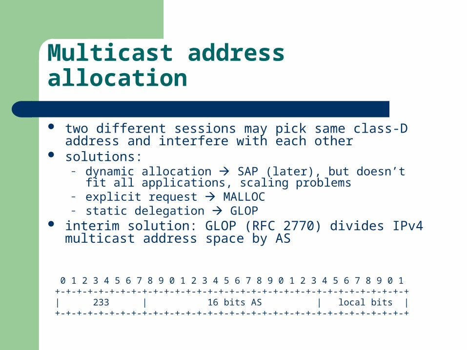
two different sessions may pick same class-D address and interfere with each other
solutions:– dynamic allocation SAP (later), but doesn’t fit all applications,
scaling problems– explicit request MALLOC– static delegation GLOP
interim solution: GLOP (RFC 2770) divides IPv4 multicast address space by AS
0 1 2 3 4 5 6 7 8 9 0 1 2 3 4 5 6 7 8 9 0 1 2 3 4 5 6 7 8 9 0 1+-+-+-+-+-+-+-+-+-+-+-+-+-+-+-+-+-+-+-+-+-+-+-+-+-+-+-+-+-+-+-+-+ | 233 | 16 bits AS | local bits | +-+-+-+-+-+-+-+-+-+-+-+-+-+-+-+-+-+-+-+-+-+-+-+-+-+-+-+-+-+-+-+-+

IPv6 multicast address allocation
RFC 3306 (“Unicast-Prefix-based IPv6 Multicast Addresses”) Like GLOP, unicast prefix based
| 8 | 4 | 4 | 112 |+--------+----+----+---------------------------------------------+|11111111|flgs|scop| group ID |+--------+----+----+---------------------------------------------+
| 8 | 4 | 4 | 8 | 8 | 64 | 32 | +--------+----+----+--------+--------+----------------+----------+ |11111111|0011|scop|reserved| plen | network prefix | group ID | +--------+----+----+--------+--------+----------------+----------+
see RFC 3307:permanent: e.g., 0x40404040 for NTP
length ofnetwork prefix

Multicast address allocation
RFC 2908 (“Internet Multicast Address Allocation Architecture”) Instance of global identifier allocation problem:
– hierarchical blocks (IEEE EUI, DNS, IP addresses, phone numbers, SSN, …)
local mechanism left unspecified– on-demand
centralized server (e.g., DHCP within domain) distributed pools
– usually, combination of both Two qualifiers:
– scope (possibly global)– lifetime (possibly indefinite)
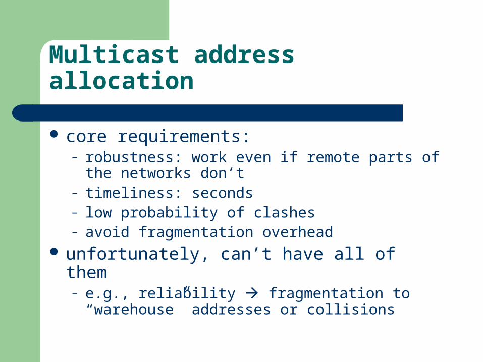
Multicast address allocation
core requirements:– robustness: work even if remote parts of the
networks don’t– timeliness: seconds– low probability of clashes– avoid fragmentation overhead
unfortunately, can’t have all of them– e.g., reliability fragmentation to “warehouse”
addresses or collisions
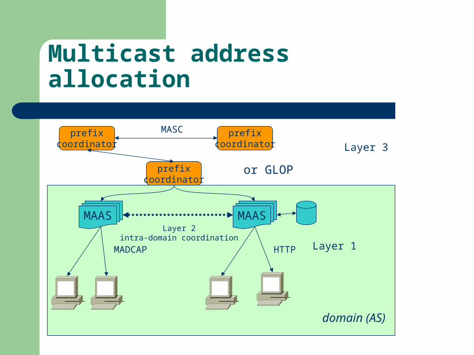
Multicast address allocation
MAAS MAAS
MADCAP HTTP
prefixcoordinator
Layer 2intra-domain coordination
Layer 1
or GLOP
prefixcoordinator
prefixcoordinator Layer 3
domain (AS)
MASC
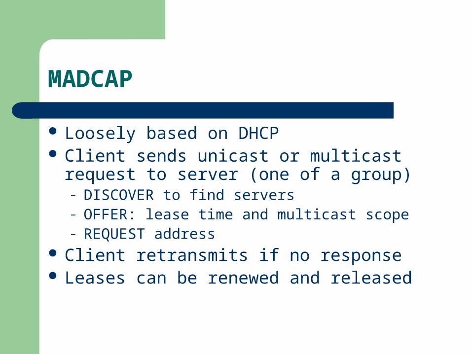
MADCAP
Loosely based on DHCP Client sends unicast or multicast request to
server (one of a group)– DISCOVER to find servers– OFFER: lease time and multicast scope– REQUEST address
Client retransmits if no response Leases can be renewed and released
PGM (Pragmatic General Multicast)
RFC 3208, PGM Reliable Transport Protocol Specification
ordered, duplicate-free multicast data from multiple sources to multiple receivers
either receives all data packets or can detect unrecoverable losses
sender retransmits after NAK routers suppress duplicate NAKs and route
retransmissions to branches in need
Multicast summary
Relatively complete architecture Difficulty of network service enhancements Difficult to meet higher-layer requirements:
– Storage and time-shifting– Access control and billing– Heterogeneous networks application-layer techniques (CDNs)
Multicast readings
Stephen A. Thomas, IPng and the TCP/IP protocols, Wiley, 1996
Christian Huitema, Routing in the Internet, Prentice Hall, 1995
J. Crowcroft, M. Handley, I. Wakeman, Internetworking Multimedia, 2000.