Embed Size (px)
Citation preview
Multicast configuration on Brocade FastIron Switches
This guide is to assist in the basic understanding and configuration of IGMP snooping and PIM
on Brocade ICX, FCX, and SX devices. More detailed information can be found in the “Brocade IP
Multicast Configuration Guide”.
IGMP snooping overview
When a device processes a multicast packet, by default, it broadcasts the packets to all ports
except the incoming port of a VLAN. Packets are flooded by hardware without going to the CPU.
This behavior causes some clients to receive unwanted traffic.
IGMP snooping provides multicast containment by forwarding traffic to only the ports that have
IGMP receivers for a specific multicast group (destination address). A device maintains the
IGMP group membership information by processing the IGMP reports and leave messages, so
traffic can be forwarded to ports receiving IGMP reports.
An IPv4 multicast address is a destination address in the range of 224.0.0.0 to 239.255.255.255.
Addresses of 224.0.0.X are reserved. Because packets destined for these addresses may require
VLAN flooding, devices do not snoop in the reserved range. Data packets destined to addresses
in the reserved range are flooded to the entire VLAN by hardware, and mirrored to the CPU.
Multicast data packets destined for the non-reserved range of addresses are snooped. A client
must send IGMP reports in order to receive traffic.
IGMP protocols provide a method for clients and a device to exchange messages, and let the
device build a database indicating which port wants what traffic. The protocols do not specify
forwarding methods. They require IGMP snooping or multicast protocols such as PIM to handle
packet forwarding. PIM can route multicast packets within and outside a VLAN, while IGMP
snooping can switch packets only within a VLAN.
If a VLAN is not IGMP snooping-enabled, it floods multicast data and control packets to the
entire VLAN in hardware. When snooping is enabled, IGMP packets are trapped to the CPU.
Data packets are mirrored to the CPU in addition to being VLAN flooded. The CPU then installs
hardware resources, so that subsequent data packets can be switched to desired ports in
hardware without going to the CPU. If there is no client report or port to queriers for a data
stream, the hardware resource drops it.

Configuring the IGMP mode
You can configure active or passive IGMP modes on the Brocade device. The default mode is
passive. If you specify an IGMP mode for a VLAN, it overrides the global setting.
• Active - When active IGMP mode is enabled, a Brocade device actively sends out IGMP
queries to identify multicast groups on the network, and makes entries in the IGMP
table based on the group membership reports it receives.
NOTE: Routers in the network generally handle this operation. Use the active IGMP
mode only when the device is in a stand-alone Layer 2 Switched network with no
external IP multicast router attachments. In this case, enable the active IGMP mode on
only one of the devices and leave the other devices configured for passive IGMP mode.
• Passive - When passive IGMP mode is enabled, it forwards reports to the router ports
which receive queries. IGMP snooping in the passive mode does not send queries.
However, it forwards queries to the entire VLAN.
Configuring the global IGMP mode
To globally set the IGMP mode, enter the following command.
device(config)#ip multicast passive
Syntax: [no] ip multicast [active | passive]
If you do not enter either active or passive, the passive mode is assumed.
Configuring the IGMP mode for a VLAN
If you specify an IGMP mode for a VLAN, it overrides the global setting.
To set the IGMP mode for VLAN 20, enter the following commands.
device(config)#vlan 20
device(config-vlan-20)#multicast passive
Syntax: [no] multicast [active | passive]

Configuring the IGMP version
Use the procedures in this section to specify the IGMP version.
Configuring the global IGMP version
When you globally enable IGMP snooping, you can specify IGMP V2 or IGMP V3. The ip
multicast version command enables IGMP V3.
device(config)#ip multicast version 3
Syntax: [no] ip multicast version [2 | 3]
If you do not specify a version number, IGMP V2 is assumed.
Configuring the IGMP version for a VLAN
You can specify the IGMP version for a VLAN. For example, the following commands configure
VLAN 20 to use IGMP V3.
device(config)#vlan 20
device(config-vlan-20)#multicast version 3
Syntax: [no] multicast version [2 | 3]
If no IGMP version is specified, then the globally-configured IGMP version is used. If an IGMP
version is specified for individual ports, those ports use that version, instead of the VLAN
version.
Overview of IP multicasting
Multicast protocols allow a group or channel to be accessed over different networks by multiple
stations (clients) for the receipt and transmission of multicast data.
PIM is a broadcast and pruning multicast protocol that delivers IP multicast datagrams. This
protocol employs reverse path lookup check and pruning to allow source-specific multicast
delivery trees to reach all group members. PIM builds a different multicast tree for each source
and destination host group.
Concurrent support for multicast routing and snooping
Multicast routing and multicast snooping instances work concurrently on the same device. For
example, you can configure PIM routing on certain VEs interfaces and snooping on other VEs or
VLANs. The limitation is that either multicast snooping or routing can be enabled on a VE
interface or VLAN, but not on both. This is because all of the multicast data and control packets

(IGMP, PIM) received on the snooping VLAN are handled by multicast snooping and do not
reach the multicast routing component. Similarly, any multicast data or control packets
received on a VE interface enabled with PIM routing are handled by the PIM routing component
and are not seen by the IGMP or PIM snooping component.
The following considerations apply when configuring concurrent operation of Multicast Routing
and Snooping.
1. Either multicast snooping or routing can be enabled on a VE or VLAN but not both.
2. Snooping can be enabled globally by configuring the ip multicast active | passive
command.
3. The global snooping configuration is inherited by all current VLANs that are not enabled
for multicast routing.
4. The global snooping configuration is also inherited by all new VLANs. Enabling multicast
routing on a newly created VLAN or VE automatically disables snooping on the VLAN or
VE.
5. When a VLAN-level snooping is configured, it is displayed.
PIM
There are two modes in which PIM operates: Dense and Sparse. The Dense Mode is suitable for
densely populated multicast groups, primarily in the LAN environment. The Sparse Mode is
suitable for sparsely populated multicast groups with the focus on WAN.
PIM uses the IP routing table instead of maintaining its own, thereby being routing protocol
independent.
Globally enabling and disabling PIM
To globally enable PIM, enter the following command.
device(config)# router pim
Syntax:[no] router pim
The [no] router pim command behaves in the following manner:
• Entering a router pim command to enable PIM does not require a software reload.
• Entering a no router pim command removes all configuration for PIM multicast on a
device (router pim level) only.

Configuring PIM interface parameters
After you enable IP multicast routing and PIM Sparse at the global level, you must enable it on
the individual interfaces connected to the PIM Sparse network.
To enable PIM Sparse mode on an interface, enter commands such as the following.
device(config)# interface ethernet 1/2/2
device(config-if-e10000-1/2/2)# ip address 207.95.7.1 255.255.255.0
device(config-if-e10000-1/2/2)# ip pim-sparse
Syntax: [no] ip [pim-sparse | pim-dense]
The commands in this example add an IP interface to port 1/2/2, then enable PIM Sparse on the
interface.
If the interface is on the border of the PIM Sparse domain, you also must enter the following
command.
device(config-if-e10000-1/2/2)# ip pim border
Syntax: [no] ip pim border
Configuring BSRs
In addition to the global and interface parameters described in the previous sections, you need
to identify an interface on at least one device as a candidate PIM Sparse Bootstrap router (BSR)
and candidate PIM Sparse rendezvous point (RP).
NOTE: It is possible to configure the device as only a candidate BSR or RP, but it is recommended
that you configure the same interface on the same device as both a BSR and an RP.
To configure the device as a candidate BSR, enter commands such as the following.
device(config)# router pim
device(config-pim-router)# bsr-candidate ethernet 1/2/2 30 255
These commands configure the PIM Sparse interface on port 1/2/2 as a BSR candidate, with a
hash mask length of 30 and a priority of 255.
Syntax: [no] bsr-candidate { ethernet unit/slot/port | loopback num | ve num | tunnel } num
hashmask-length [ priority ]
The ethernet unit/slot/port, loopback num, ve num, and tunnel num parameters specify the
interface.
The device will advertise the IP address of the specified interface as a candidate BSR.

• Enter ethernet unit/slot/port for a physical interface (port).
• Enter ve num for a virtual interface.
• Enter loopback num for a loopback interface.
• Enter tunnel num for a GRE tunnel interface.
The numhash-mask-length variable specifies the number of bits in a group address that are
significant when calculating the group-to-RP mapping. You can specify a value from 1 to 32.
NOTE: it is recommended that you specify 30 for IP version 4 (IPv4) networks.
The priority variable specifies the BSR priority. You can specify a value from 0 to 255. When the
election process for BSR takes place, the candidate BSR with the highest priority becomes the
BSR. The default is 0.
Configuring RPs
Enter a command such as the following to configure the device as a candidate RP.
device(config-pim-router)# rp-candidate ethernet 1/2/2
Syntax: [no] rp-candidate ethernet { ethernet unit/slot/port | loopback num | ve num | tunnel
num }
The ethernet unit/slot/port, loopback num, ve num, and tunnel num parameters specify the
interface.
The device will advertise the IP address of the specified interface as a candidate RP.
• Enter ethernet unit/slot/port for a physical interface (port).
• Enter ve num for a virtual interface.
• Enter loopback num for a loopback interface.
• Enter tunnel num for a GRE tunnel interface.
By default, this command configures the device as a candidate RP for all group numbers
beginning with 224. As a result, the device is a candidate RP for all valid PIM Sparse group
numbers. You can change this by adding or deleting specific address ranges.
The following example narrows the group number range for which the device is a candidate RP
by explicitly adding a range.
Device(config-pim-router)# rp-candidate add 224.126.0.0 16
Syntax: [no] rp-candidate add group-addr mask-bits

The group-addr mask-bits variable specifies the group address and the number of significant
bits in the subnet mask. In this example, the device is a candidate RP for all groups that begin
with 224.126.
When you add a range, you override the default. The device then becomes a candidate RP only
for the group address ranges you add.
You also can delete the configured rp-candidate group ranges by entering the following
command.
device(config-pim-router)# rp-candidate delete 224.126.22.0 24
Syntax: [no] rp-candidate delete group-addr mask-bits
The usage of the group-addr mask-bits parameter is the same as for the rp-candidate add
command.

Show Commands
Displaying the IGMP snooping configuration
To display the global IGMP snooping configuration, enter the show ip multicast command at
any level of the CLI.
Displaying IGMP group information
To display default, maximum, current, and configured values for system maximum parameters,
use the show default values command. The following output example does not show complete
output; it shows only IGMP group values.
To display information about IGMP groups, enter the show ip multicast group command.

Displaying IGMP snooping mcache information The IGMP snooping mcache contains multicast forwarding information for VLANs. To display information in the multicast forwarding mcache, enter the show ip multicast mcache command.
Displaying the status of IGMP snooping traffic
To display status information for IGMP snooping traffic, enter the show ip multicast traffic
command.
Displaying basic PIM Sparse configuration information To display PIM Sparse configuration information, enter the following command at any CLI level.

Displaying a list of multicast groups To display PIM group information, enter the following command at any CLI level.
Displaying PIM mcache table entries
To display PIM mcache information, enter the following command at any CLI level.
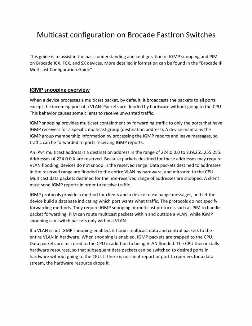
Displaying BSR information To display BSR information, enter the following command at any CLI level.
Displaying candidate RP information To display candidate RP information, enter the following command at any CLI level.

Example:
The following example shows how to configure IGMP snooping and PIM-Sparse on two
networks that need to transport multicast information from a source to a client. For this
example, we are using Brocade ICX routers and switches as the infrastructure. We are using VLC
as the source on a server and VLC player on two windows clients on different networks.
Figure 1:
Router-RP10.100.0.1
Router_A10.100.0.2
Switch_A Switch_B
Client 1VLAN 30
10.10.30.100
Client 2VLAN 10
10.20.10.100
Router-RP Configuration
ver 08.0.30dT7f3 ! stack unit 1 module 1 icx6610-48-port-management-module module 2 icx6610-qsfp-10-port-160g-module module 3 icx6610-8-port-10g-dual-mode-module stack-trunk 1/2/1 to 1/2/2

stack-trunk 1/2/6 to 1/2/7 stack mac 748e.f8e6.cc80 ! global-stp ! vlan 1 name VLAN1 by port tagged ethe 1/1/43 to 1/1/47 spanning-tree 802-1w spanning-tree 802-1w priority 8192 ! vlan 10 name Network by port tagged ethe 1/1/1 ethe 1/1/3 to 1/1/10 ethe 1/1/35 to 1/1/36 ethe 1/1/43 to 1/1/47 ethe /3/1 ethe 1/3/3 untagged ethe 1/1/12 to 1/1/20 router-interface ve 10 spanning-tree 802-1w spanning-tree 802-1w priority 8192 ! vlan 20 name Voice by port tagged ethe 1/1/1 to 1/1/10 ethe 1/1/35 to 1/1/36 ethe 1/1/43 to 1/1/47 ethe 1/3/1 ethe /3/3 router-interface ve 20 spanning-tree 802-1w spanning-tree 802-1w priority 8192 ! vlan 30 name Guest by port tagged ethe 1/1/35 to 1/1/36 ethe 1/1/43 to 1/1/47 ethe 1/3/1 ethe 1/3/3 router-interface ve 30 spanning-tree 802-1w spanning-tree 802-1w priority 8192 ! vlan 40 name Servers by port tagged ethe 1/1/35 to 1/1/36 ethe 1/1/43 to 1/1/47 ethe 1/3/1 ethe 1/3/3 router-interface ve 40 spanning-tree 802-1w spanning-tree 802-1w priority 8192 ! vlan 1000 name OSPF by port tagged ethe 1/3/2 router-interface ve 1000 ! vlan 1499 name DEFAULT-VLAN by port spanning-tree 802-1w spanning-tree 802-1w priority 8192

! ! aaa authentication web-server default local aaa authentication enable default enable aaa authentication login default local aaa authentication login privilege-mode default-vlan-id 1499 enable password-display enable super-user-password brocade hostname RP-Router ip route 0.0.0.0/0 10.0.0.1 ! no telnet server username admin password brocade fdp run ! clock summer-time clock timezone us Central ! ntp server 129.6.15.28 server 129.6.15.29 server 129.6.15.30 ! ! hitless-failover enable ip multicast-routing! ! ! router ospf area 0 ! router pim bsr-candidate ve 1000 30 255 rp-candidate ve 1000 rp-candidate add 224.0.0.0 4 ! ! interface ve 10 ip address 10.10.10.1 255.255.255.0 ip pim-sparse ! interface ve 20 ip address 10.10.20.1 255.255.255.0

ip pim-sparse ip helper-address 1 10.10.10.50 ! interface ve 30 ip address 10.10.30.1 255.255.255.0 ip pim-sparse ip helper-address 1 10.10.10.50 ! interface ve 40 ip address 10.10.40.1 255.255.255.0 ip pim-sparse ip helper-address 1 10.10.10.50 ! interface ve 1000 ip address 10.100.0.1 255.255.255.0 ip pim-sparse ip ospf area 0 ! lldp run ! end
Router_A Configuration
ver 08.0.30dT213 ! stack unit 1 module 1 icx7450-24-port-management-module module 2 icx7400-xgf-4port-40g-module module 3 icx7400-qsfp-1port-40g-module module 4 icx7400-qsfp-1port-40g-module priority 128 stack-port 1/3/1 1/4/1 stack unit 2 module 1 icx7450-24-port-management-module module 2 icx7400-xgf-4port-40g-module module 3 icx7400-qsfp-1port-40g-module module 4 icx7400-qsfp-1port-40g-module stack-port 2/3/1 2/4/1 stack enable stack mac cc4e.2488.7cc8 ! global-stp

! ! ! vlan 10 name Network by port tagged ethe 1/2/4 router-interface ve 10 spanning-tree 802-1w spanning-tree 802-1w priority 8192 ! vlan 20 name Voice by port tagged ethe 1/2/4 router-interface ve 20 spanning-tree 802-1w spanning-tree 802-1w priority 8192 ! vlan 30 name Guest by port tagged ethe 1/2/4 router-interface ve 30 spanning-tree 802-1w spanning-tree 802-1w priority 8192 ! vlan 40 name Servers by port tagged ethe 1/2/4 router-interface ve 40 spanning-tree 802-1w spanning-tree 802-1w priority 8192 ! vlan 1000 name OSPF by port tagged ethe 1/2/3 router-interface ve 1000 ! vlan 1499 name DEFAULT-VLAN by port ! aaa authentication web-server default local aaa authentication enable default enable aaa authentication login default local aaa authentication login privilege-mode default-vlan-id 1499 enable password-display enable super-user-password brocade hostname Router_A ! username admin password brocade fdp run
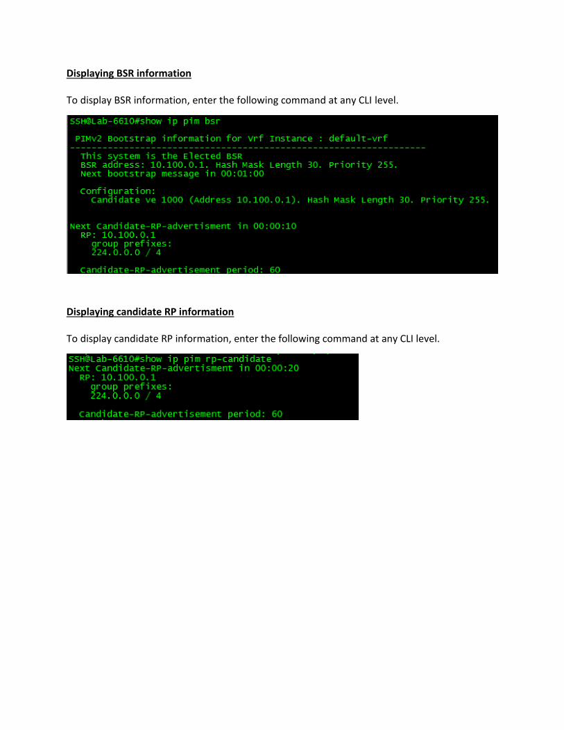
! clock summer-time clock timezone us Central ! ntp server 129.6.15.28 server 129.6.15.29 server 129.6.15.30 ! hitless-failover enable ip multicast-routing ! router ospf area 0 ! router pim bsr-candidate ve 1000 30 1 rp-candidate ve 1000 rp-candidate add 239.0.0.0 24 ! interface ve 10 ip address 10.20.10.1 255.255.255.0 ip pim-sparse ip helper-address 1 10.10.10.50 ip ospf area 0 ip ospf passive ! interface ve 20 ip address 10.20.20.1 255.255.255.0 ip pim-sparse ip helper-address 1 10.10.10.50 ip ospf area 0 ip ospf passive ! interface ve 30 ip address 10.20.30.1 255.255.255.0 ip pim-sparse ip helper-address 1 10.10.10.50 ip ospf area 0 ip ospf passive ! interface ve 40 ip address 10.20.40.1 255.255.255.0 ip pim-sparse

ip helper-address 1 10.10.10.50 ip ospf area 0 ip ospf passive ! interface ve 1000 ip address 10.100.0.2 255.255.255.0 ip pim-sparse ip ospf area 0 ! lldp run ! end
Switch Configuration
SwitchA and Switch_B configuration is configured with the required VLANs and the following command:
ip multicast passive