Embed Size (px)
Citation preview
Multi-View Sketching & Projection
Aerospace Practicum
Spring 2007
Created by:
P.M. Larochelle
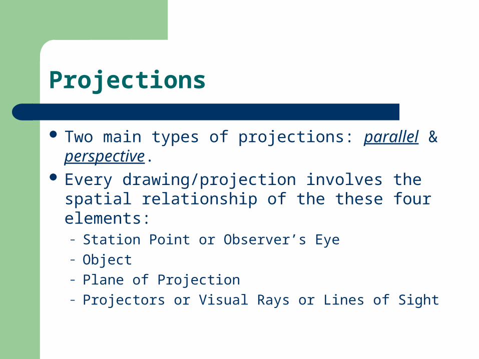
Projections
Two main types of projections: parallel & perspective.
Every drawing/projection involves the spatial relationship of the these four elements:– Station Point or Observer’s Eye– Object– Plane of Projection– Projectors or Visual Rays or Lines of Sight
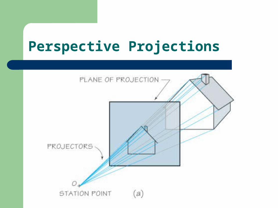
Perspective Projections
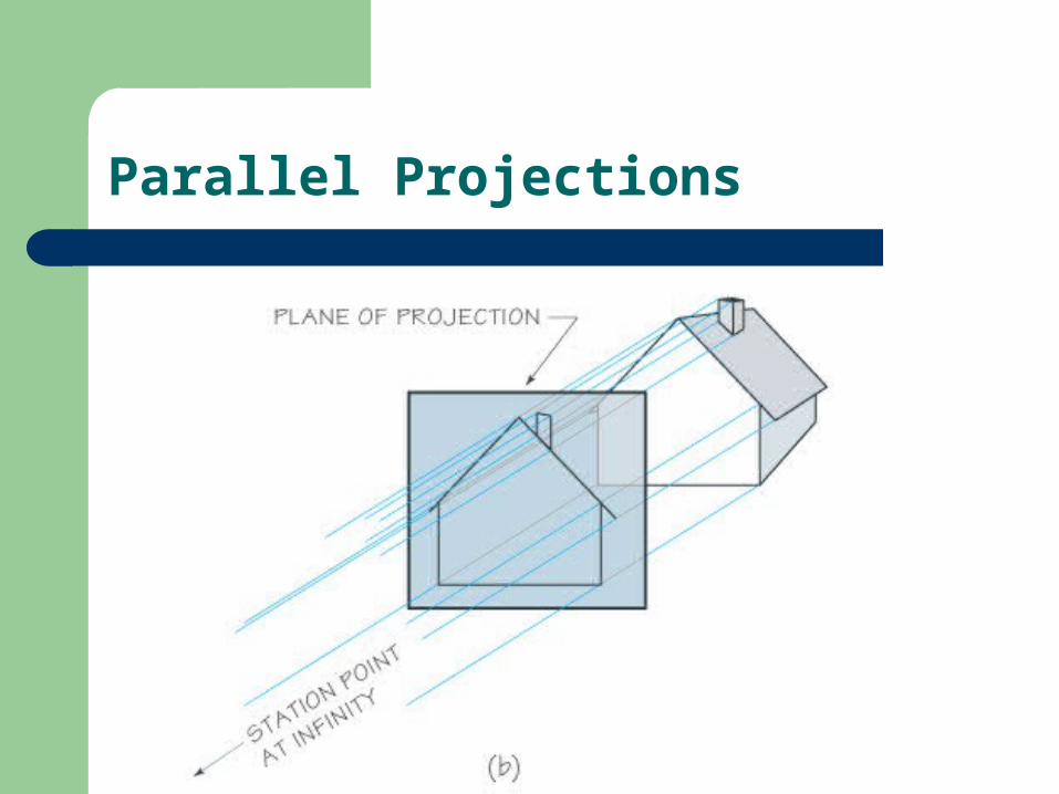
Parallel Projections
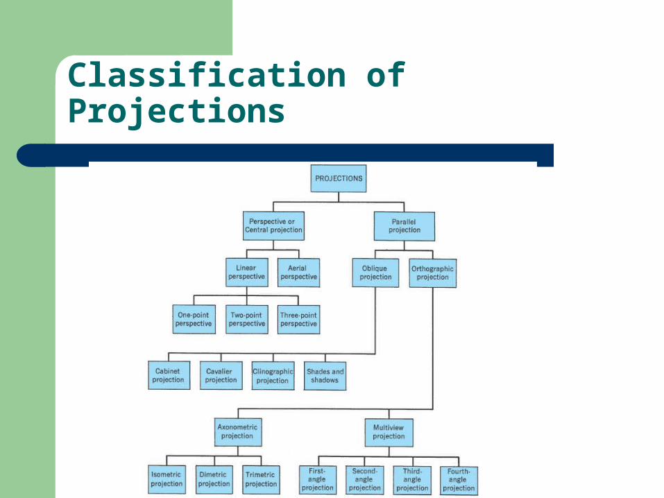
Classification of Projections
Object Views
To provide a clear and complete description of the shape and size of an object a number of views, systematically arranged, are used. This system of object representation is called multi-view projection.
Multi-view projection is necessary since all objects are 3-D and all drawings are 2-D. One 2-D drawing is insufficient to clearly and completely define an object.
Object Views
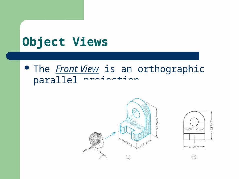
The Front View is an orthographic parallel projection.
Object Views
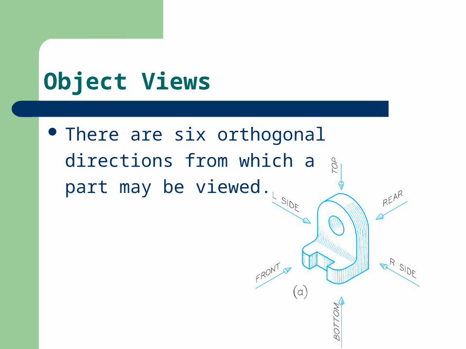
There are six orthogonal
directions from which a
part may be viewed.
Object Views
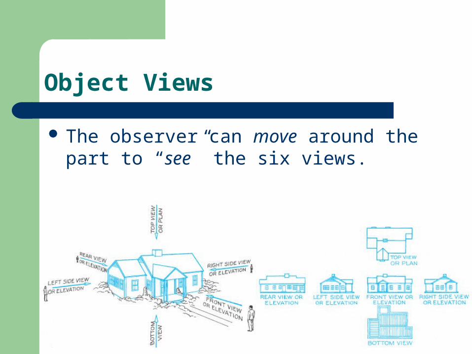
The observer can move around the part to “see” the six views.
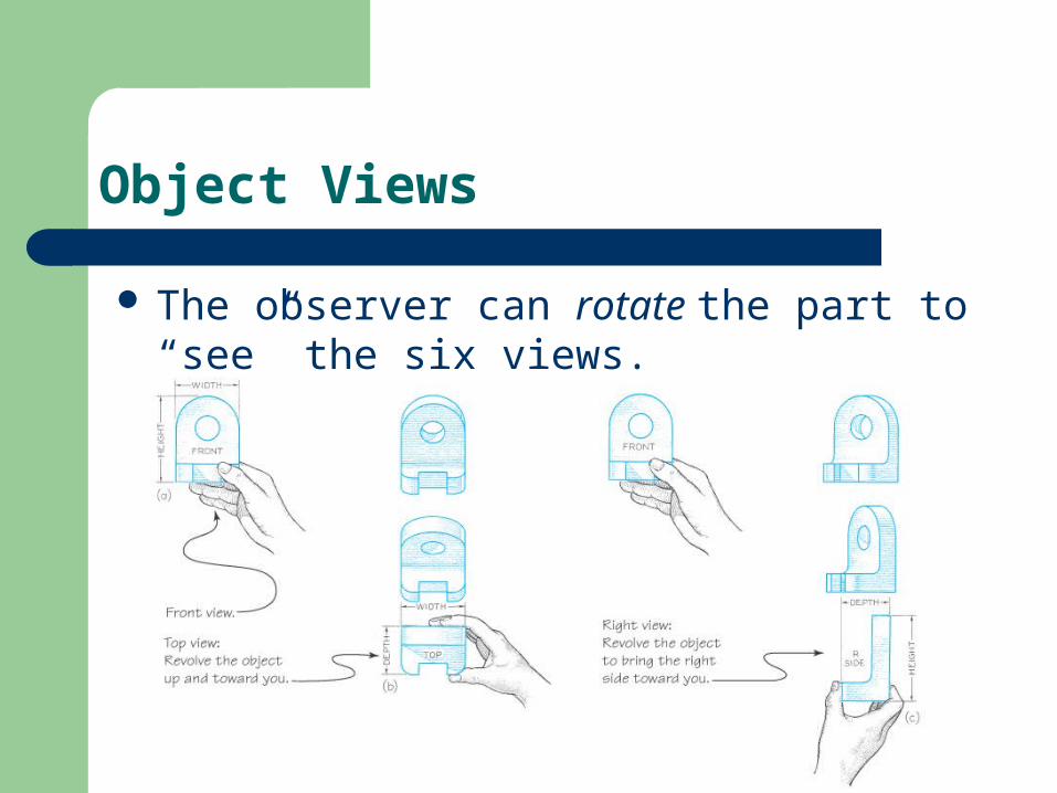
Object Views
The observer can rotate the part to “see” the six views.
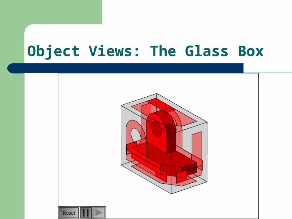
Object Views: The Glass Box
The Six Standard Views
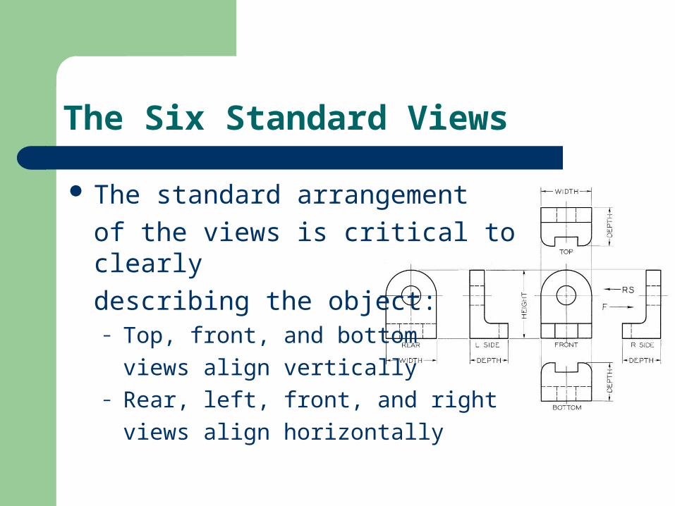
The standard arrangement
of the views is critical to clearly
describing the object:– Top, front, and bottom
views align vertically– Rear, left, front, and right
views align horizontally
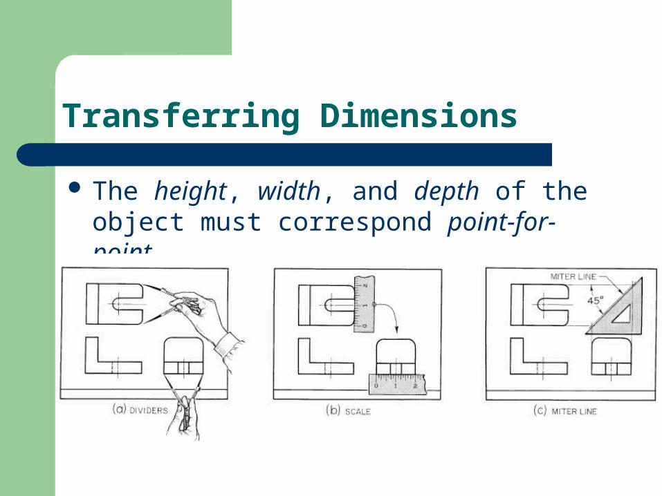
Transferring Dimensions
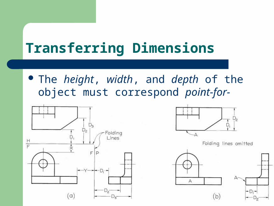
The height, width, and depth of the object must correspond point-for-point.
Transferring Dimensions
The height, width, and depth of the object must correspond point-for-point.
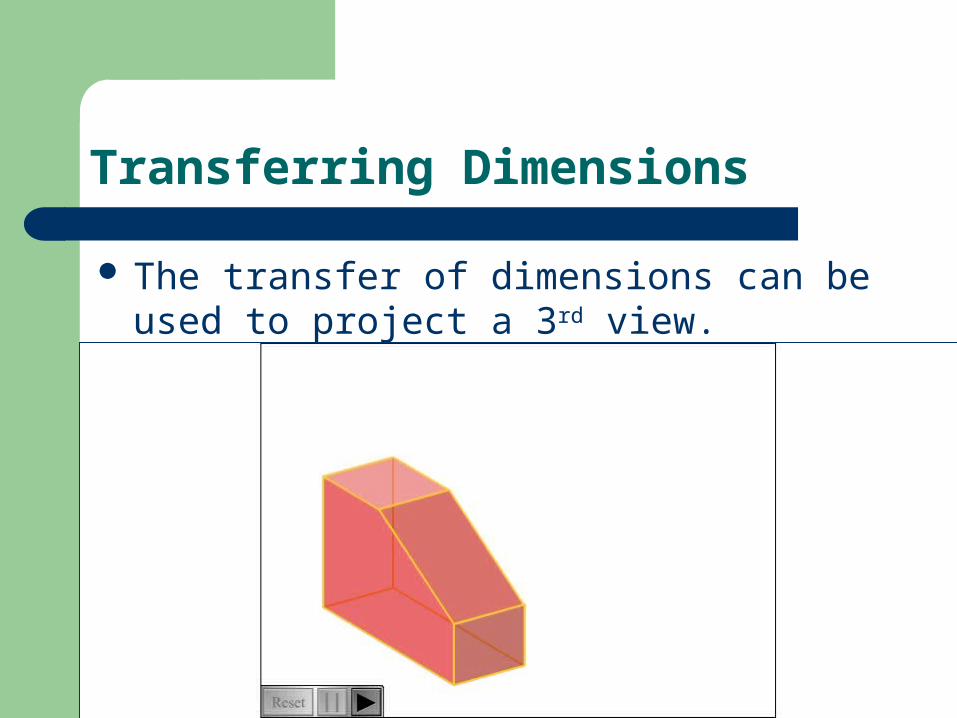
Transferring Dimensions
The transfer of dimensions can be used to project a 3rd view.
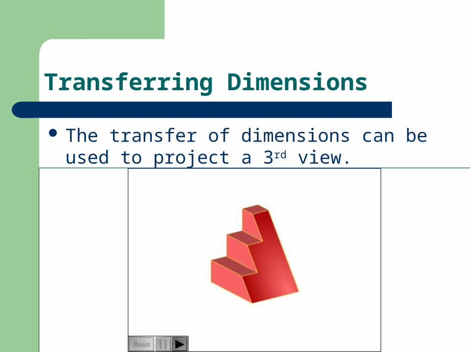
Transferring Dimensions
The transfer of dimensions can be used to project a 3rd view.
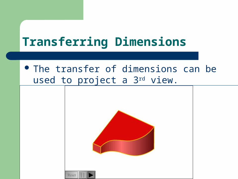
Transferring Dimensions
The transfer of dimensions can be used to project a 3rd view.
Necessary Views
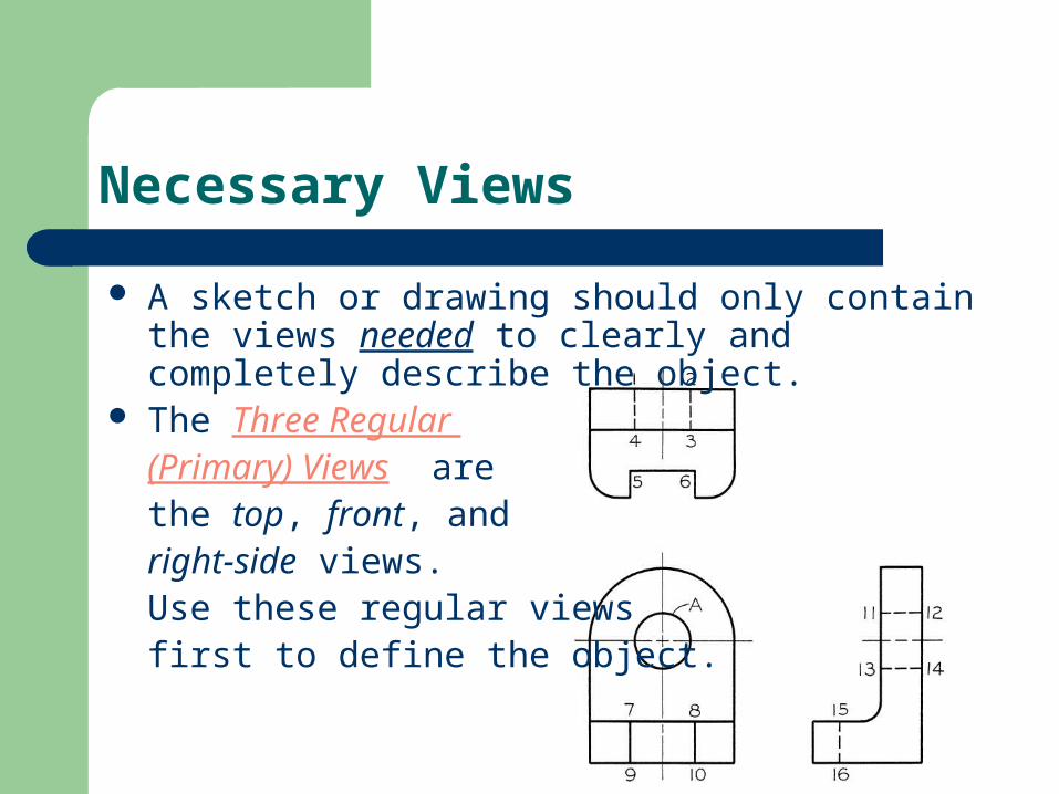
A sketch or drawing should only contain the views needed to clearly and completely describe the object.
The Three Regular (Primary) Views are the top, front, and right-side views. Use these regular views first to define the object.
Choosing the Necessary Views
Orient the object so that the front view shows the features of interest most clearly
Chose the front view such that it has a large number of normal surfaces
Show the object in the usual or operating orientation Next, show the right-side and/or top views unless
other views are better(fewer hidden lines) Show only the views need to fully define the object’s
geometry See Step-by-Step 5.9 & Hands-On 5.6 pg. 144.
Elements of a Projection: points
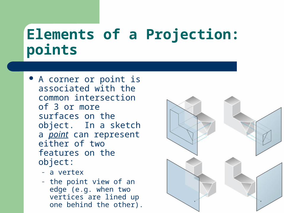
A corner or point is associated with the common intersection of 3 or more surfaces on the object. In a sketch a point can represent either of two features on the object:
– a vertex– the point view of an edge
(e.g. when two vertices are lined up one behind the other).
Elements of a Projection: lines
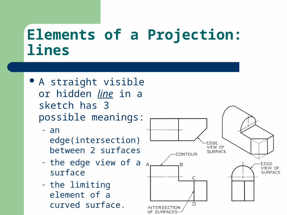
A straight visible or hidden line in a sketch has 3 possible meanings:– an edge(intersection)
between 2 surfaces– the edge view of a
surface– the limiting element
of a curved surface.
Elements of a Projection: hidden lines
Dashed hidden lines are used to represent features that would be hidden behind other surfaces.
Remember to choose views that show features with visible lines when possible then use hidden lines to make the drawing clear.
Elements of a Projection: hidden lines
Use dashes 1/8” long with 1/16” long gaps.
Should intersect neatly except where a line of a different line type would appear to be extended.
Should “jump” visible lines that they cross
Draw closely spaced parallel hidden lines with the staggered dashes
See Step-by-Step 5.5 pg. 132 for sketching guidelines
Hidden Lines:
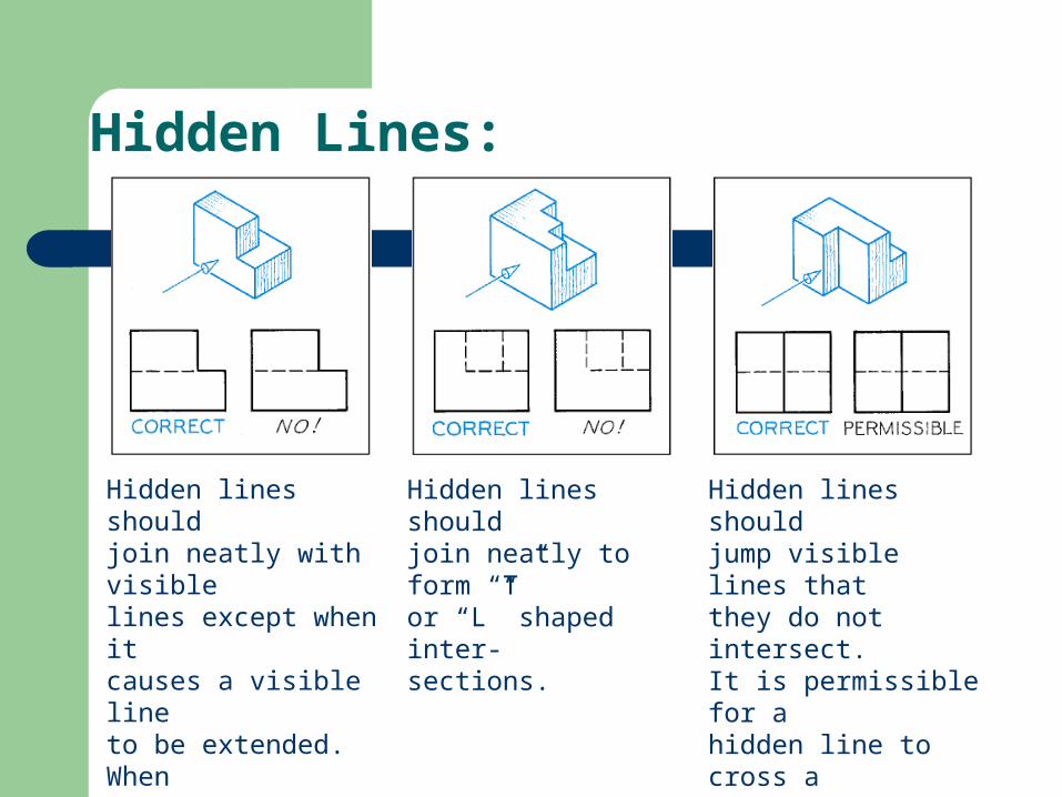
Hidden lines shouldjoin neatly with visiblelines except when itcauses a visible lineto be extended. Whentwo different lines jointo form a single line, leave a gap on the lessimportant line.
Hidden lines shouldjoin neatly to form “T”or “L” shaped inter-sections.
Hidden lines shouldjump visible lines thatthey do not intersect.It is permissible for ahidden line to cross avisible line.
Hidden Lines:
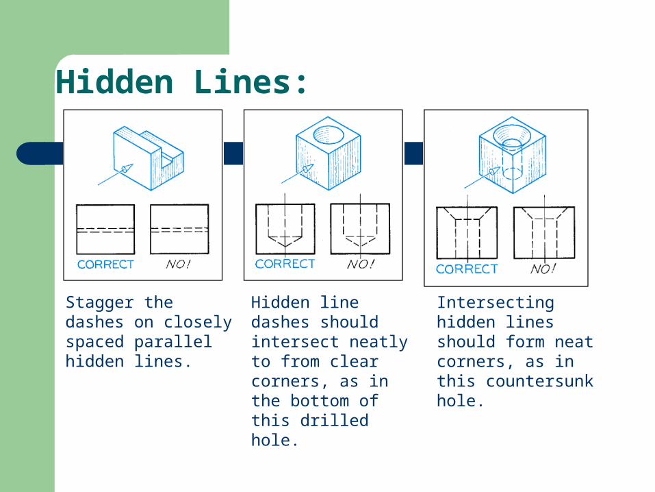
Stagger the dashes on closely spaced parallel hidden lines.
Hidden line dashes should intersect neatly to from clear corners, as in the bottom of this drilled hole.
Intersecting hidden lines should form neat corners, as in this countersunk hole.
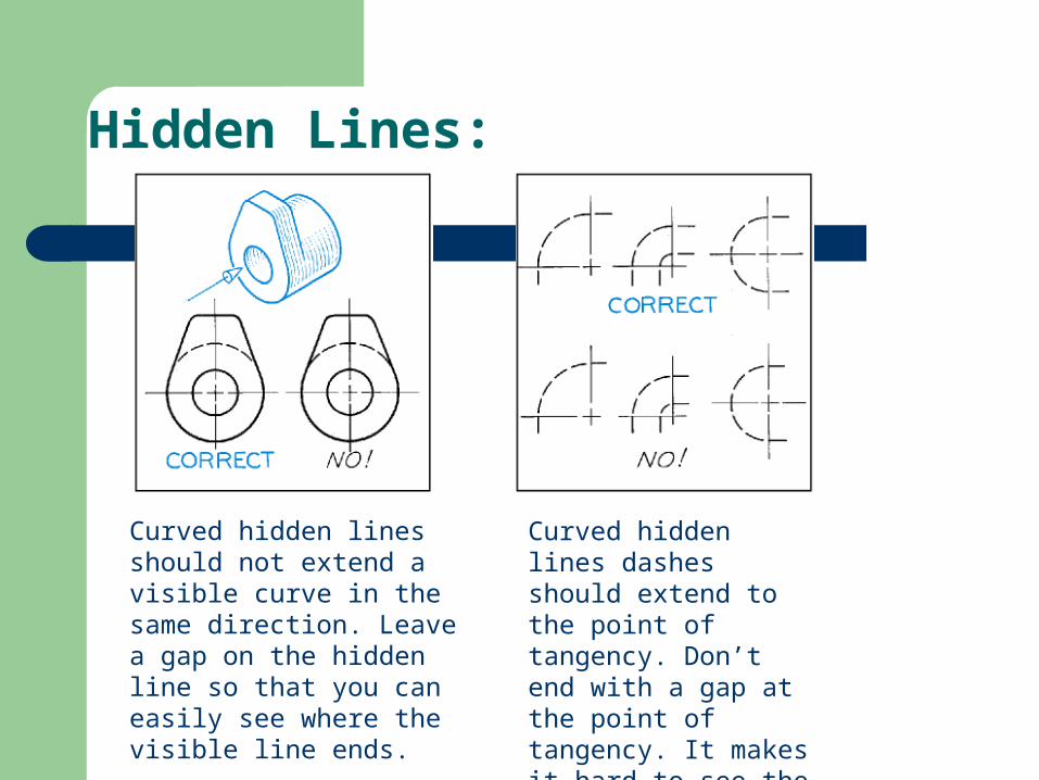
Hidden Lines:
Curved hidden lines should not extend a visible curve in the same direction. Leave a gap on the hidden line so that you can easily see where the visible line ends.
Curved hidden lines dashes should extend to the point of tangency. Don’t end with a gap at the point of tangency. It makes it hard to see the location.
Elements of a Projection: fillets & rounds
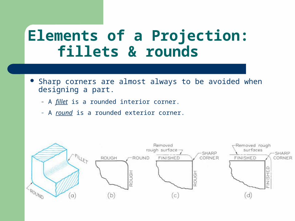
Sharp corners are almost always to be avoided when designing a part.
– A fillet is a rounded interior corner.
– A round is a rounded exterior corner.
Center Lines:
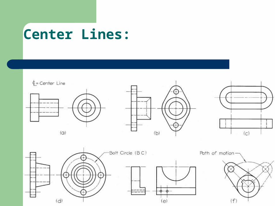
Center lines are used to indicate symmetrical axes of objects or features, bolt circles, and paths of motion.
Centerlines are useful in dimensioning as the are used to locate the center of the feature.
Centerlines are not needed on fillets, rounds, or other self-locating features.
Center Lines:
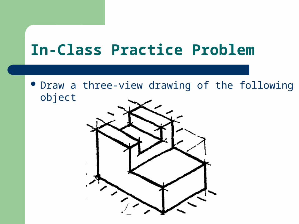
In-Class Practice Problem
Draw a three-view drawing of the following object
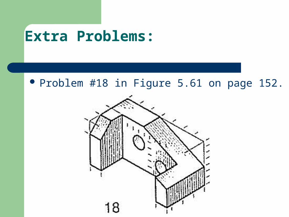
Extra Problems:
Problem #18 in Figure 5.61 on page 152.
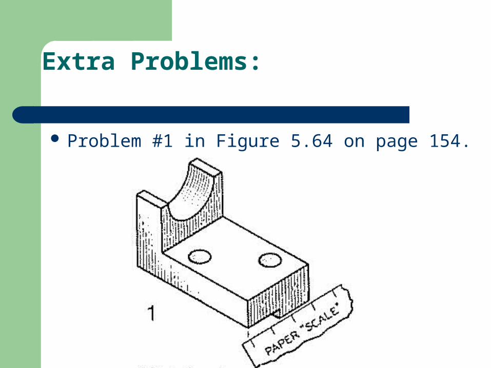
Extra Problems:
Problem #1 in Figure 5.64 on page 154.
References
Chapter 5 of Modern Graphics Communication by Giesecke, Mitchell, Spencer, Hill, Dygdon, Novak, and Lockhard, 3rd edition. Prentice-Hall, 2004.
Technical Drawing by Giesecke, Mitchell, Spencer, Hill, Dygdon, and Novak, 9th edition. Macmillan, 1991.