Embed Size (px)
Citation preview

© 2015 Danhong Huang, Fei Gao, D.A. Cardimona, C.P. Morath and V.M. Cowan. This open access article is distributed
under a Creative Commons Attribution (CC-BY) 3.0 license.
American Journal of Space Science
Original Review Paper
Multi-Timescale Microscopic Theory for Radiation
Degradation of Electronic and Optoelectronic Devices
1Danhong Huang,
2Fei Gao,
1D.A. Cardimona,
1C.P. Morath and
1V.M. Cowan
1Air Force Research Laboratory, Space Vehicles Directorate, Kirtland Air Force Base, NM 87117, USA 2Department of Nuclear Engineering and Radiological Sciences,
University of Michigan, 500 S. State Street, Ann Arbor, Michigan 48109, USA Article history
Received: 13-01-2015
Revised: 21-02-2015
Accepted: 29-04-2015
Corresponding Author:
Danhong Huang
Air Force Research Laboratory,
Space Vehicles Directorate,
Kirtland Air Force Base, NM
87117, USA Email: [email protected]
Abstract: A multi-timescale hybrid model is proposed to study
microscopically the degraded performance of electronic devices, covering
three individual stages of radiation effects studies, including ultra-fast
displacement cascade, intermediate defect stabilization and cluster
formation, as well as slow defect reaction and migration. Realistic
interatomic potentials are employed in molecular-dynamics calculations
for the first two stages up to 100 ns as well as for the system composed of
layers with thicknesses of hundreds of times the lattice constant. These
quasi-steady-state results for individual layers are input into a rate-
diffusion theory as initial conditions to calculate the steady-state
distribution of point defects in a mesoscopic-scale layered-structure
system, including planar biased dislocation loops and spherical neutral
voids, on a much longer time scale. Assisted by the density-functional
theory for specifying electronic properties of point defects, the resulting
spatial distributions of these defects and clusters are taken into account in
studying the degradation of electronic and optoelectronic devices, e.g.,
carrier momentum-relaxation time, defect-mediated non-radiative
recombination, defect-assisted tunneling of electrons and defect or
charged-defect Raman scattering as well. Such theoretical studies are
expected to be crucial in fully understanding the physical mechanism
for identifying defect species, performance degradations in field-effect
transistors, photo-detectors, light-emitting diodes and solar cells and in
the development of effective mitigation methods during their
microscopic structure design stages. Keywords: Radiation Effects in Semiconductor Devices, Radiation-
Induced Defects in Semiconductors, Radiation-Induced Degradation of
Semiconductor Device Performance
Introduction
Point defects (vacancies and interstitial atoms) are
produced by the displacements of atoms from their
lattice sites, (Was, 2007; Sigmund, 2006) where the
atom displacements are mainly induced by a Primary
Knockout Atom (PKA) on a time scale shorter than 50
ps. This initial phase is followed subsequently by a
defect reaction (clustering or dissolution of clusters),
(Devanathan et al., 2001) and further by the thermally
activated migration (Posselt et al., 2005) of the point
defects and defect clusters over a time scale longer than
100 ns. The combination of all these processes, resulting
in a significant concentration of surviving defects in the
crystal, is physically termed particle irradiation
displacement damage (in addition to the well know γ-ray
electron ionization cascade damage). Such radiation
displacement damage effects depend not only on the
energy-dependent flux of the incident particles (protons,
neutrons, ions, etc.) but also on the differential energy
transfer cross sections (probabilities) for collision
between atoms, interatomic Coulomb interactions and
kinetic-energy loss to electrons inside an atom.
Irradiation temperature also significantly affects the
motion of defects, their stability as clusters and the
formation of Frenkel pairs (Gao and Weber, 2003a). On the other hand, electron devices are usually
classified either as electronic ones, where electrons

Danhong Huang et al. / American Journal of Space Science 2015, 3 (1): 3.27
DOI: 10.3844/ajssp.2015.3.27
4
respond to an applied voltage as a current flow, or optoelectronic ones, in which electrons perform interband/intraband optical transitions in the presence of an incident light signal. (Gumbs and Huang, 2013) For an electronic device (e.g., field-effect transistors in an integrated circuit), the momentum-relaxation time of electrons, due to scattering by randomly-distributed defects, plays a crucial role in determining the electron mobility, (Strour et al., 2003) while the photo-excited electron lifetime, due to nonradiative recombination with defects, is proven to be a key factor affecting the sensitivity or the performance of optoelectronic devices (e.g., photo-detectors and light-emitting diodes) (Weatherford and Anderson, 2003).
In a perfect crystal, the continuous free-electron
states are quantized into many Bloch bands separated
by energy gaps and these Bloch electrons move freely
inside the crystal with an effective mass different
from that of the free electrons (Callaway, 1991). In
the presence of defects, however, the field-driven
current flow of Bloch electrons in a perfect crystal
will be scattered locally by these defects, leading to a
reduced electron mobility. In addition, photo-excited
Bloch electrons could acquire a shortened lifetime,
giving rise to a degraded quantum efficiency due to
enhanced non-radiative recombination with defects.
The dangling bonds attached to the point defects may
capture extra electrons to form charged defects. In this
case, the positively-charged holes in the system will
be trapped to produce a strong spacecharge field,
while the negatively-charged electrons may generate
the so-called 1/f-current noise in their chaotic motion
due to the presence of many potential minima and
maxima from randomly-distributed charged defects.
Point defects in crystals, as shown in Fig. 1, can be
generated by particle irradiation in both bulk and
nanocrystals composed of many grains with different
sizes (Gao et al., 2010). One of the effective
calculation methods for studying the non-thermal
spatial-temporal distributions of radiation-induced
point defects is the Molecular-Dynamics (MD) model
based on a stepped time-evolution approach (also
termed the collisional and thermal spike stages),
which involves the total force by summing over the
interatomic potentials from all the atoms in a finite
system (Gao et al., 2009). The lattice vibration at
finite temperatures can be taken into account by an
initial thermal-equilibrium state for atoms (intrinsic
vacancies and interstitials) in the system plus an
initial velocity for one of the atoms in a specific
direction. The system size increases quadratically with
the initial kinetic energy of particles and the time
scale runs up to several hundred picoseconds (called
the quenching stage). Therefore, the defect reaction
process by thermal migration cannot be included in
this MD model due to its much longer time scale,
although the other processes, such as displacement of
lattice atoms, energy dissipation, spontaneous
recombination and clustering, can be fully taken into
account. If the system time evolution goes beyond 100 ps,
the kinetic lattice Monte-Carlo method can also be used
(Rong et al., 2007). However, if the time scale exceeds
several hundreds of nanoseconds (also called the annealing
stage), the rate theory (Maksimov and Ryazanov, 1980;
Golubov et al., 2012) has to be called in for studying the
steady-state properties of the surviving defects (up to
hours or days or even months). We know that the MD model with a realistic
interatomic potential has been developed for studying
the nonthermal spatial-temporal distributions of
radiation-induced point defects in noble transition
metals and alloys and the density-functional theory
has been widely used for calculating electronic
properties of defects with pre-assumed specific defect
configurations. On the other hand, a quantum-
mechanical model has been well established for
investigating defect effects on semiconductor
electronic devices in the presence of spatially-uniform
and randomly distributed point defects. However, to
the best of our knowledge, no first-principle model
and theory has been proposed so far to study
microscopically the degraded performance of
electronic devices induced by particle irradiation
displacement damage.
Therefore, the theory presented in this study is
expected to be very important in understanding the
full mechanism for characterizing defects, performance
degradations in transistors, photo-detectors, light-
emitting diodes and solar cells, as well as in developing
effective mitigation in early design stages. Equipped
with our current multi-timescale microscopic theory, the
experimental characterization of post-irradiated test
devices will result in useful information on the device
architecture’s susceptibility to space radiation effects
(we already know details on particle irradiation sources).
On the other hand, the model should allow prediction of
devices degradation on the basis of space weather
forecast for the particular orbit.
Some of the equations presented below will be
well-known to researchers in the materials science
field, however, researchers in the device physics field
may not be aware of them. With this paper, we hope
to bridge the gap between researchers studying
radiation-induced damage in materials and researchers
studying radiation-induced performance degradation
in devices. This should allow the formalism developed
for the investigation of radiation-induced structural
defects in nuclear reactor materials to be extended to
the investigation of device performance degradation
effects induced by particle radiation found in space-
based systems.
Danhong Huang et al. / American Journal of Space Science 2015, 3 (1): 3.27
DOI: 10.3844/ajssp.2015.3.27
5
Fig. 1. Two-dimensional illustrations of different types of point defects in a crystal
The rest of the paper is organized as follows. In section II, we present our atomic-scale MD model to cover both the ultra-fast defect generation and intermediate defect stabilization stages, as well as the mesoscopic-scale rate theory for defect migration and interaction processes. In Section III, master equations for both planar dislocation-loop and spherical void growth are introduced for studying surface and bulk sink dynamics, respectively. In section IV, master equations are presented for exploring the steady-state spatial distribution of defects in layered structure materials. In addition, a density-functional theory is introduced for specifying electronic properties of point defects and four device physics models are employed for characterizing and understanding defect-assisted resonant tunneling, reduced carrier mobility, non-radiative recombination with defects and inelastic light scattering by charged defects. In section V, an indication of how this defect theory might be applied to experimental data describing device performance degradation is presented. Finally, some concluding remarks are presented in section VI.
Model and Theory
Atomic-Scale Modeling for Ultrafast Defect
Generation (Displacement Cascade: t < 100 ps)
A schematic of a displacement-cascade event by proton irradiation is shown in Fig. 2. For the neutron-nucleus elastic collision, this process can be simply regarded as colliding hard spheres as an approximation due to their charge neutrality. The more complicated inelastic collision of neutrons with a nucleus, however, could involve generating an additional neutron [(n, 2n)-process] or photon emission [(n, γ)-process], which are both important to the displacement of atoms. For the proton-nucleus elastic collision, on the other hand, the
extra interaction (potential function) between the electron cloud and the proton should be considered.
Commonly, the end product of a particle collision
results in the PKA having an excess kinetic energy and
the subsequent atom-atom interaction represents the
most fundamental physical mechanism of the radiation
displacement damage (Gao and Weber, 2000a; Gao and
Weber, 2003b). Since radiation damage events are
random in nature, a large number of damage events are
required to obtain good statistics by choosing different
directions and locations for the PKA. On the other hand,
the dynamics in the damage procedure can be accurately
described by employing a realistic interatomic potential
(MD model). For incident charged particles, the detailed
form of the interatomic potential depends on the closest
separation between two collision partners, which itself is
determined by the kinetic energy of the incident particles
(e.g., heavy-slow ions and relativistic electrons). The point defect generation as a result of
displacement cascades is closely related to the PKA energy, which can be described statistically by an average transfer energy to the PKA. Such an average transfer energy can be calculated by using the energy-loss theory and measured by the so-called proton (electron) energy-loss spectroscopy (Gumbs, 1989) as a function of various incident charged particle energies. The defects can also be identified experimentally by using positron annihilation (Tuomisto and Makkonen, 2013). With help from the computed energy loss of incident particles per unit length (called the loss function), the range of the particle before its full stop inside a crystal can be found. On the other hand, the MD method has been widely employed to simulate defect generation in a number of semiconductors, including Si, (Rubia and Gilmer, 1995) SiC, (Gao and Weber, 2000) GaAs, (Nordlund et al., 2001) and GaN (Nord et al., 2003).

Danhong Huang et al. / American Journal of Space Science 2015, 3 (1): 3.27
DOI: 10.3844/ajssp.2015.3.27
6
Fig. 2. Two-dimensional schematic of a displacement cascade induced by incident protons on a crystal These simulations provide important insights into the mechanisms for defect generation in semiconductors and predict the number and type of defects, spatial distribution of defects and initial correlation among defect species produced by the incident radiation for subsequent device level models.
Basically, in MD simulations the time evolution of a
set of interacting particles is tracked via the solution of
Newton’s equations of motion as shown below:
2
2
( )( )
j
j j
d r tF t m
dt= (1)
where, the indices j = 1, 2,..., N label individual N
particles in the system, rj(t) [xj(t), yj(t), zj(t)] is the
position vector of the jth particle and ( )j j jk
k j
F t V
≠
= − ∇∑ is
the force acting upon the jth particle at time t with
interacting potential Vjk between the jth and kth particle
and mj is the mass of the corresponding particle. In
general, Fj(t) will depend on both particle positions and
velocities at time t. Here, the energy loss of protons to
electrons is ignored due to thin samples considered. To
integrate the above second-order differential equations,
the instantaneous forces acting on the particles and their
initial positions and velocities need to be specified. Due
to the many-body nature of the problem, the equations of
motion have to be discretized and solved numerically.
The MD trajectories are defined by both position vector
rj (t) and velocity vector ( )
( )j
j
dr tv t
dt= and they describe
the time evolution of the system in position-velocity
phase space. Accordingly, the positions and velocities
are propagated with a small time interval ∆t using
numerical integrators. The numerical integration of
Newton’s equations of motion is employed to find an
expression that defines positions rj (t + ∆t) at time t + ∆t
in terms of the already known positions rj(t) at time t.
Because of its simplicity and stability, the Verlet
algorithm is commonly used in MD simulations.
(Frenkel and Smit, 2002) However, other popular
algorithms, such as Leapfrog, Velocity Verlet, Beeman’s
algorithms, (Frenkel and Smit, 2002; Allen and
Tildesley, 1987) predictor-corrector, (Gear, 1971) and
symplectic integrators, (Tuckerman and Martyna, 2000)
are also widely adopted. For non-PKA particles, their two
initial conditions can be set as rj(−∆t) = rj (0) = Rj, where
Rj is the lattice vector for the jth site. If the PKA is given
an initial velocity v0, in addition to 0(0)PKA PKA
r r= this leads
to another initial condition 0 0
( )PKA PKAr t r v t−∆ = − ∆ .
In MD simulations, the atomic force field is crucial to determine physical systems in which collections of atoms are kept together by interatomic forces that can be calculated from empirical or semi-empirical interatomic potentials. Because of extensive applications of MD methods in materials science, a variety of techniques have been utilized over the years to develop reliable atomic-potential models. One of the early successful attempts to include manybody effects was the introduction of the embedding functional, (Norskov and Lang, 1980) which depends nonlinearly upon the coordination number (defined below) of each atom. This development led to the birth of the Embedded Atom Method (EAM), (Finnis and Sinclair, 1984) which provides a relatively accurate description for noble transition metals as well as their alloys. However, the Tersoff potential formalism (Tersoff, 1988) is based on the concept of bond order and has been widely applied to a large number of semiconductors. Novel many-body forms have been tried in an attempt to capture as much

Danhong Huang et al. / American Journal of Space Science 2015, 3 (1): 3.27
DOI: 10.3844/ajssp.2015.3.27
7
as possible the physics and chemistry of the bonding. A typical analytical form is constituted by a number of functions, depending on geometrical quantities, such as distances or orientations, or on intermediate variables, such as atom coordinations. For example, a Tersoff potential has the appearance of a pair potential as below:
, 1 , 1 , 1
1 1 1( ) ( )
2 2 2
N N N
ij R ij ij A ij
i j i j i j
V V r B rφ φ= = =
= = +∑ ∑ ∑ (2)
where, the terms with i = j are excluded in the above
summations, rij = |ri - rj | and the first and second terms
represent repulsive and attractive interactions,
respectively. However, the second term in Equation (2)
is not a true pair potential since Bij is not a constant. In
fact, it is the bond order for the bond joining the ith and
jth atoms and it is a decreasing function of a
“coordination” Gij assigned to the bond. Therefore, we
have Bij = B(Gij ) and Gij is in turn defined by:
( ) ( ) ( )ij c ik ijk c jk
k
G f r g f rθ=∑ (3)
where, fc(r) and g(θ) are suitable functions. The basic idea is that the i-j bond is weakened by the presence of other i-k and j-k bonds involving the intermediate atom at site k. The amount of bond weakening is determined by where the other bonds are. Angular terms appear necessary to construct a realistic model. When using a potential, the researcher should always be familiar with its chemical transferability properties, such as bond length, bond angle and bond energy and validate critically the results obtained in unusual conditions, for example, for very low coordinations, very high temperature, or very high pressure.
Atomic-Scale Modeling for Intermediate Defect
Stabilization (Stable Defect and Cluster
Formations: 100 ps<t<10 ns)
The atom-displacement-generated point defects
(vacancies and interstitial atoms) under particle
irradiation will thermally diffuse in space and interact
and react with dynamically distributed bulk sinks, planar
dislocation loops, (Hirth and Lothe, 1982) spherical
voids and clusters (due to collision cascade) at the same
time. Generally, the kinetic energy of the incident
particles (or equivalently, the recoil energy of the struck
atom) determines the species and number of individual
point defects during the initial phase (in addition to the
rate of defect generation), while the flux of the incident
particles decides the defect density and the nature of
point-defect diffusion, (Mehrer, 2007) i.e., either in an
independent way (for lowdensity non-interacting point
defects) or in a direction-correlated way (for high-
density interacting point defects) (Posselt et al., 2008).
The macroscopic property changes of the irradiated
system are related to the particle energy-flux per unit
time by the so-called damage function, or factor, which
is extracted by experimental measurements. However,
the damage factor is found to depend on the initial
approximation in a sensitive way. Therefore, we are not
able to treat physically the radiation displacement
damage effects as a black box through a fitting
procedure. Instead, we should understand the full
dynamics of these defects on all time scales after they
have been produced. The spatial distribution of the
mobile Frenkel pairs (i.e., vacancy-interstitial pairs)
that are created is crucial in determining the number
that survive annihilation or immobilization by
clustering due to damage cascade.
The statistically-averaged spatial distribution of point
defects that are generated can be calculated based on the
defect formation and recombination rates, as well as the
follow-up processes for defect diffusion, interactions and
reactions (Posselt et al., 2005). If the degree of atom
displacements is limited due to high incident particle
kinetic energies and low number intensities, we
generally seek the radiation degradation effects on
electronic and optoelectronic devices rather than looking
at material level radiation damage effects when there is a
significant level of atom displacements under intense
low-energy particle irradiation (Strour et al., 2003). This
radiation degradation depends not only on the particle
radiation source and material, but also on the device
structure and functionality. The analytical theory
below can only provide a qualitative understanding of the
collision- and thermally-activated diffusion processes,
while the MD calculation based on a realistic interatomic
potential is able to provide a quantitative result for
comparison with experimental data.
Point-Defect Generation Rate
The spatially-temporally-dependent damage rate per
unit volume for the displacement atoms in a crystal can
be calculated from (Was, 2007):
max
min
0( , ) ( ) ( )
E
at i D i ext i
E
G r t n d r I tε σ ε ε= ∫ (4)
where, nat is the crystal atom volume density, Iext(t|εi)
represents the external dynamical energy-dependent
particle intensity per unit energy, σD(r|εi) stands for both
the position- and energy-dependent displacement cross
section and Emin (Emax) corresponds to the minimum
(maximum) kinetic energy in the energy distribution of
incident particles.
Since the displacement cross section σD(r|εi) in
Equation (4) physically describes the probability for the
displacement of struck lattice atoms by incident
particles, we can directly write down:

Danhong Huang et al. / American Journal of Space Science 2015, 3 (1): 3.27
DOI: 10.3844/ajssp.2015.3.27
8
2
1
( ) ( , ) ( )D i R C i R D Rr d r N t
ε
ε
σ ε ε σ ε ε ε= ∫ (5)
where, σC(r|εi, εR) is the differential energy transfer cross
section by collision, which measures the probability that
an incident particle with kinetic energy εi will transfer a
recoil energy εR to a struck lattice atom, ND(r|εR)
represents the average number of displaced atoms due to
collision and ε1 (ε2) labels the minimum (maximum)
recoil energy acquired by the struck lattice atom.
Although ND(r|εR) can be directly determined by MD
simulation, (Terentyev et al., 2006) the simplest
approximation to estimate the displaced atoms is the
Kinchin-Pease model (for a solid composed of randomly
arranged atoms by ignoring focusing and channeling
effects). (Kinchin and Pease, 1955; Olander, 1976) In
practice, ND(r|εR) can be accurately determined by either
classic (Devanathan et al., 1998) or ab initio MD
simulations (Gao et al., 2011).
In addition, the magnitude of the differential energy
transfer cross section σC(r|εi, εR) introduced in Equation
(5), which can be regarded as the crystal response to an
external particle collision with lattice atoms, depends on
the detailed collision mechanism and the form of the
scattering potential as well. Here, as a simple example, we
first give the expression of the differential energy transfer
cross section for the elastic scattering. For the well-known
Rutherford elastic scattering model (Rutherford, 1911)
based on an unscreened Coulomb potential UR(ρ) =
Z1Z2e/ ∈0ρ for protons with ρ being the radius in the local
frame centered on the lattice atom, we get:
2
0
2
( ) ( )( , ) ( , )
4
iC i R R i R
R
b r rr r
π ε γσ ε ε σ ε ε
ε≡ = (6)
where, γ(r) = 4mM(r)/[M(r) + m]2, m [M(r)] is the mass
of the incident particle (surface atoms or different lattice
atoms), b0(r) = Z1Z2(r) e2/η(r)∈0εi with Z1 and Z2(r)
being the nuclear charge numbers for particles and
different lattice atoms and η(r) = m/[M(r) + m].
If the kinetic energy of the incident particles is very
high, the Rutherford scattering model becomes no longer
applicable. In this case, we have to consider hard-sphere
type collisions for neutrons, which leads to:
2( )
( , ) ( , )( ) ( )
C i R HS i R
i i
B r Ar r In
r r
πσ ε ε σ ε ε
γ ε η ε
≡ =
(7)
where, a Born-Mayer potential UB-M(ρ) = A exp(-ρ/B) is
employed (Abrahamson, 1969).
On the other hand, nuclear scattering with heavy-
slow ions represented by a power-law interacting
potential UI(ρ) = (e/∈0aB) (Z1/Z2)5/6(aB/ρ)
2 leads to:
2
2 2 2
( , ) ( , )
4 ( ) ( ) ( )
( ) [1 4 ( )] ( )[1 ( )]
C i R I i R
a
i
r r
E r r r
r r X r X r
σ ε ε σ ε ε
ξ
γ ε ξ
≡
Λ=
− −
(8)
where, X(r) = εR/γ(r)εiζ(r) 1 1/6
1 2cos ( ) / , ( ) 0.8853 / [ ( )]
BX r r a Z Z rπ
− = Λ = is the
screening length with aB being the Bohr radius and Ea(r)
= (e2/∈0aB) [Z1/Z2(r)]
7/6/η(r).
In the special case, for the incidence of relativistic
light electrons, we have:
2 4 2
2 0
2 2 4 4
0 0 0
2 0 2
0 2
2 0 2 2
1( , ) ( , )
( ) ( )1
( ) ( ) ( )
C i R I i R
R R R
R
Z er r
m c
a r E r
E r E r E r
π βσ ε ε σ ε ε
β
ε ε εβ π
β ε
−≡ =
∈
× − + −
(9)
where, β0 = υ/c with υ being the velocity of incident
electrons, E2(r) = [2εi/M(r)c2](εi+2m0c
2), m0 is the free-
electron mass and α0(r) = Z2(r)/137. Moreover, we have
the relation 2 2 2
0 01 ( / ) 1
im cβ ε= − ≤ for the relativistic-
particle velocity and kinetic energy.
For the case of isotropic inelastic scattering with an
energy loss Q0, we have the differential energy transfer
cross section:
'
1/2
00
( , ) ( , )
( , ) ( ) ( ) 11
( ) ( )
C i R in i R
is i
i i
r r
r Q Q r A r
r A r
σ ε ε σ ε ε
σ ε
γ ε ε
−
≡
+= +
(10)
where, A(r) = M(r)/m and σis (r|εi, Q0) represents the
isotropic differential energy transfer cross section for the
resolved resonance in the center-of-mass frame.
In addition, the incident-particle kinetic energy is no
longer a constant if the particles are charged, e.g., protons
and ions. In this case, we have 2
0( ) / 2
i iz kzε ε ε
→ = −
with ε0 being the incident-particle energy at the left
boundary z = 0, where a layered structure in the z-
direction is assumed. As a result, we find that electronic
stopping will dominate at short distances, while elastic
collisions will dominate near the end of the range. As an example, by using σC(r|εi, εR) from Equation (6)
and ND(r|εR) from the Kinchin-Pease model, the displacement cross section from Equation (5) becomes:
( )( ) ( )
4 ( )D i s i
th
rr r
E r
γσ ε σ ε
≈
(11)
where, 2
0( ) ( ) / 4 ( ) / ( )s i i thr b r r E rσ ε π γ ε = .
Furthermore, by using the result in Equation (11), the

Danhong Huang et al. / American Journal of Space Science 2015, 3 (1): 3.27
DOI: 10.3844/ajssp.2015.3.27
9
displacement damage rate per unit volume from
Equation (4) is:
0
( ) ( )( , ) ( ) ( , )
4 ( )
i
at s ext
th
r rG r t n r F r t
E r
ε γσ
=
(12)
where, ( )srσ and ( )rε are the average values with
respect to the incident particle intensity per unit energy
Lext(t|εi) in the energy range of Eth (r)/γ≤εi≤Fext(r,t) is the
integrated external particle intensity for the same energy
range and the term in the bracket is the number of
Frenkel pairs produced per incident particle.
Point-Defect Diffusion Coefficient
Even in the absence of particle irradiation, there still
exist some thermally activated vacancies at room
temperature in a crystal. In this case, the Helmholtz free-
energy function in thermodynamics can be applied by
assuming the volume of the crystal is a constant. In the
presence of crystal defects, both the entropy S and the
enthalpy Hp of a perfect crystal will be changed. A
straightforward calculation gives the thermal-equilibrium
numbers of vacancies eq
vC and interstitials eq
iC as follows:
, ,
,
exp expv i v ieq
v i
B B
S EC
k k T
=
(13)
where T is the temperature, Ev is the vacancy formation
energy, which is smaller than the interstitial formation
energy Ei and Sv (Si) is the change in entropy due to
vibrational vacancy (interstitial) disorder.
Diffusion of defects is driven by forces other than the
concentration gradient of defects, such as stress or strain,
electric fields, temperature, etc. The second Fick’s law
(Murty and Charit, 2013) directly gives rise to the
following diffusion equation on the macroscopic scale:
,
, ,
( , )[ ( , ) ( , )]
v i
v i v i
C r tD r t C r t
t
∂= −∇ ⋅ ∇
∂ (14)
where, Dv(r, t) = D(r, t|Cv) and Di(r, t) = D(r, t|Ci) are
called the diffusion coefficients for vacancy and
interstitial atoms, respectively and cv,i(r, t) = Cv,i(r, t)/V is
the defect concentrations with V being the volume of the
system considered. In addition, by assuming a microscopic random walk
for the diffusion process, we get the Einstein formula (Guinan et al., 1977):
2
0
( ) 1( ) ( )exp ( ) ( )
6
ac
d
B
E rD r D r r r
k Tλ
= − = Γ
(15)
where, the temperature-independent part, D0(r), is
proportional to the Debye frequency (∼ 10THz) and is
independent of defect concentration, Eac(r) is the
activation energy for thermal diffusion λd(r) is the
diffusion length and Γ(r) is the defect jump rate.
For tracer-atom (single radiative atom) diffusion, the
random-walk model can not be used. Instead, the
diffusion process becomes correlated, described by the
Haven coefficient f(r) and we obtain 2( ) ( ) ( ) ( ) / 6d
D r f r r rλ= Γ where f(r)<1 depends on the
crystal structure and the diffusion mechanism.
The lattice-atom correlated diffusion coefficients , ( , )v i
aD r t for vacancy and interstitial cases are given by:
,
, , ,
( , ) ( ) ( ) ( , )v i
a v i v i v iD r t f r D r C r t= (16)
which depend on the defect concentrations in this case,
implying a nonlinear diffusion equation. It should be noted
that the correlation factors, fv,i(r) and diffusion coefficients,
Dv,i(r), can be determined by atomic-level simulations
(Guinan et al., 1977; Posselt et al., 2008). Equation (16) can
be directly applied to defect diffusion under irradiation, as
long as the defect concentrations are known.
Mesoscopic-Scale Rate Theory for Slow Defect
Migration and Interaction (Defect Reaction and
Migration: t > 10 ns)
The formation, growth and dissolution of defect
clusters such as voids, dislocation loops, etc., depend on
the diffusion of point defects and their reaction with these
defect clusters (Bullough et al., 1979; Colubov et al.,
2000). At the same time, they also depend on the
concentration of point defects in the crystal. Since
particle irradiation greatly raises the defect concentration
above its thermal-equilibrium value, the diffusion
coefficient can be enhanced. It can also be enhanced by
the creation of new defect species.
Point-Defect Diffusion Equation
By introducing the local coupling rates ( , ), ( , )is
r t r tℜ Γ
and Γvs(r, t) for vacancy-interstitial recombination,
interstitial-sink and vacancy-sink reaction rates, we can
write down the following two nonlinear rate-based diffusion
equations for binary crystals (Wiedersich et al., 1979):
0
( , )[ ( , ) ( , )] ( , )
( , ) ( , ) ( , )[ ( , ) ( )]
( , ) ( , )[ ( , ) ( )]
( , )[ ( , ) ( , )] ( , )
v
v
i
C
v v vC
eq
i v v
eq
vs s v v
cii i ic
r t
D r t c r t J r t ct
G r t R r t c r t c r t c r
r t c r t c r t c r
r tD r t c r t J r t c
t
∂
= ∇ ⋅ ∇ −∇ ⋅∂
+ − −
−Γ −
∂= ∇ ⋅ ∇ −∇ ⋅
∂
(17)
0( , ) ( , ) ( , )[ ( , ) ( )]
( , ) ( , )[ ( , )
eq
i v v
is s i
G r t R r t c r t c r t c r
r t c r t c r t
+ − −
−Γ (18)
Danhong Huang et al. / American Journal of Space Science 2015, 3 (1): 3.27
DOI: 10.3844/ajssp.2015.3.27
10
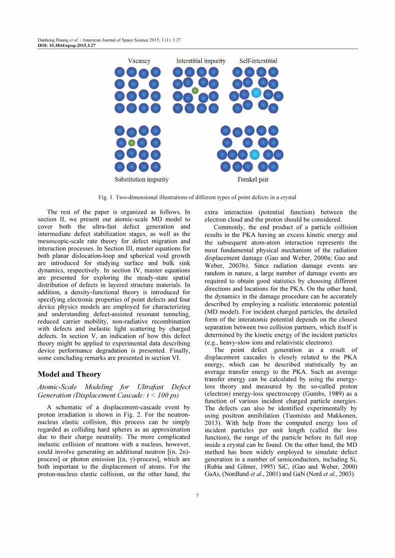
where, we have neglected correlated diffusions and
defect-defect interactions. Moreover, Jv(r, t|cv) and
Ji(r, t|ci) in Equations (17) and (18) are the particle
currents for vacancies and interstitials and the master
equation for determining the local sink concentration
cs(r,i) will be given later.
For simplicity, we consider a homogeneous system
with volume V in the absence of vacancy and interstitial
currents and assume all the rates are independent of time.
We further neglect the small thermal-equilibrium
vacancy concentration and write the defect generation
rate as G0 = G0V. For this model system, we find that the
evolution of cv(t) and ci(t) depends on the temperature
and cs and can be characterized in several regimes
separated by different time scales τ, including initial
buildup without reaction, dominant vacancy-interstitial
mutual recombination and final vacancy and interstitial
annihilation by sinks. Physically, it is easy to understand
that the initial buildup and recombination regimes
correspond to the ‘ultra-fast’ atomic-scale modeling,
while the interstitial and vacancy annihilation regimes
are associated with the ‘slow’ mesoscopic-scale
modeling which may be simulated using the so-called
rate theory (Singh and Zinkle, 1993) or phase field
model (Li et al., 2010).
Recombination and Sink Annihilation Rates
In general, the reaction rate between species A and
B can be expressed as ΓAB cA cB where cA and cB are
the concentrations (particles/cm3) and ΓAB (cm
3/s) is
the rate constant.
As an example, the recombination rate constant
( , )r tℜ in Equation (17) and (18) for vacancies and
interstitials takes the form of (Waite, 1957):
2
0
( ) ( ) ( , )( , )
( )
iv iz r r D r t
r ta r
Ωℜ = (19)
where, ziv(r) (an integer) is the bias factor, depending on
the crystal structure and species, Ω(r) is the atomic
volume, a0(r) is the lattice constant and Di(r, t) is the
mobile interstitial diffusion coefficient.
In a similar way, the interstitial-sink Γis(r, t) or the
vacancy-sink Γvs(r, t) annihilation rate constants in
Equations (17) and (18) are given by Γas(r, t) ca(r, t) cs(r,
t) 2 ( , ) ( , ) ( , )as a ak r t c r t D r t= , where α corresponds to mobile
defect species and καs(r, t) (cm−2) represents the sink
strength given by (Doan and Martin, 2003):
2( , ) ( , )
( , )( , )
as s
as
a
r t c r tr t
D r tκ
Γ= (20)
The sink strength measures the affinity of a sink for
defects, which is independent of defect properties and
1( , )as
r tκ− corresponds to the mean distance for a traveling
defect in the crystal before it is trapped by sinks.
Point-Defect Interaction Rates
In the absence of the macroscopic-scale gradient of
defect concentration, the reaction between defects and
sinks is reaction-rate-controlled. According to Equation
(19), the defect-void interaction (Brailsford et al., 1976)
can be described by the rate constants Γi,vV(r, t) by:
2
,
,
2 0
2
,
2
4 ( , ) ( , )( , )
( )
( , ) ( , )
( , )
i v
i v v
n
V i v
n V
R r t n D r tr t
a r
r t n D r t
c r t n
π
κ
∞
=
∞
=
Γ =
=
∑
∑
(21)
where, 2 2 3
, 0 04 / , , ( , )
i v Vz R a a R r t nπ= Ω ∼ represents the
radius of a void sphere involving n vacancies. The void
strength is given by 2 2
0( , ) 4 ( , ) ( , ) / ( )V Vr t n R r t n c r t n a rκ π=
where cV(r, t|n) is the concentration of voids containing n
vacancies in the crystal.
Similarly, for the defect-dislocation interaction, we
have the rate constants Γi,vd(r,t) (Heald and Speight,
1975) (in units of cm2/s) given by:
2
, ,
, , ,
( , ) ( , )( , ) ( ) ( , )
( , )
i v d i v
i v d i v d i v
d
r t D r tr t z r D r t
r t
κ
ρΓ = = (22)
where, we replace Ω in Equation (19) by an atomic
area 2
0( ), ( ) ( )
id vda z r z r≠∼ and ρdr,t(r, t) is the dislocation
areal density.
Reactions driven by defect concentration gradients
are diffusion limited instead of reaction-rate limited as
discussed above. In this case, we have to solve the diffusion
term ∇· [Di,v(r, t) ∇ci,v(r, t)] with the generation term G0(r, t)
for spherical (voids) or cylindrical (dislocation lines)
coordinates. In the case of dislocation loops, the sink
strength is more complicated and increases with increasing
loop size (Bullough et al., 1979).
For the defect-void interaction, we get
, , , ,
2
( , ) ( , ), ( , ) 4 ( , ) ( , )i v V i v V i v V i v
n
r t r t n r t n R r t n D r tπ
∞
=
Γ = Γ Γ =∑
and 2 ( , )4 ( , ) ( , )V Vr t n R r t n c r t nκ π . For the defect-dislocation
line interaction, on the other hand, we have
, , 0 , ( , ) 2 ( , ) / [ / ( , )]
i v d i v i v dr t D r t In R R r tπΓ = and
2
, 0 , ( , ) / [ / ( , )]
i v d i v dr t In R R r tκ , where R0 is the
absorption radius of a sink, Rid(r, t) and Rvd(r, t) are
the sink capture radii for interstitials and vacancies,
respectively with id vd
R R≫ .
In the presence of Grain Boundaries (GBs), we obtain
the grain-boundary sink strength:

Danhong Huang et al. / American Journal of Space Science 2015, 3 (1): 3.27
DOI: 10.3844/ajssp.2015.3.27
11
2
,
, ,
,
, ,
( , ) 4 ( ) ( )
( , ) ( )cosh[ ( , ) ( )]
sinh[ ( , ) ( )]
sinh[ ( , ) ( )] [ ( , ) ( )
i v gb gb gb
i v gb i v gb
i v gb
i v gb i v gb
r t R r c r
r t R r r t R r
r t R r
r t R r r t R r
κ π
κ κ
κ
κ κ
=
− ×
−
(23)
where, Rgb(r) is the radius of a spherical grain, cgb(r)
is the grain concentration and κi,v(r, t) is the sink
strength for the grain interior for interstitlals or
vacancies due to dislocations and voids. Moreover, its
rate constant is 2
, , ,( , ) ( , ) ( , ) / ( )i v gb i v gb i v gbr t r t D r t c rκΓ = .
More recently, atomic-level simulations have been
employed to study the sink strength of grain
boundaries (Tschopp et al., 2012; Jiang et al., 2014).
These simulations revealed that the sink strength can
exceed the theoretical strength of GBs due to the
effect of GB stress fields.
Radiation-Induced Segregation
For a binary A-B alloy (or donor and acceptor
randomly-doped semiconductors), in the absence of
sinks, the diffusion equations for vacancies, interstitials
and atoms A and B are (Wiedersich et al., 1979):
0
0
( , )( , ) ( , ) ( , ) ( , ) ( , )
[ ( ) ( )] ( , ) ( ) ( , )
( , ) ( , ) ( , )
( , ) ( , ) ( , ) ( , )
v
v i v
Av Bv v
A v v
i v
c r tJ r t G r t r t c r t c r t
t
d r d r X r t r c r t
c r t D r t c r t
G r t r t c r t c r t
∂= −∇ + −ℜ
∂
= ∇ − − Ω
∇ + ∇
+ −ℜ
i
(24)
0
0
( , )( , ) ( , ) ( , ) ( , ) ( , )
[ ( ) ( )] ( , ) ( )
( , ) ( , ) ( , ) ( , )
( , ) ( , ) ( , ) ( , )
v
v i v
Ai Bi
i A i i
i v
c r tJ r t G r t r t c r t c r t
t
d r d r X r t r
c r t c r t D r t c r t
G r t r t c r t c r t
∂= −∇ ⋅ + −ℜ
∂
= ∇ − − Ω
∇ + ∇
+ −ℜ
(25)
( , ). ( , ) ( ) ( , ) ( , )
( ) ( , )[ ( ) ( , ) ( ) ( , )]
v
A A A
A Ai i Av v
c r tJ r t D r X r t c r t
t
r c r t d r c r t D r c r t
∂= −∇ +∇ ∇
∂
+Ω ∇ − ∇
(26)
where, 2
, , , , , , ( ) ( ) ( ) ( )
A B i v i v i v A B i vd r r z r rλ ω= are the
diffusivity coefficients and the dimensionless X(r,t) is
the thermodynamic factor connecting the chemical-
potential gradient to the concentration gradient (or
built-in electric field at junctions). In addition, we
have cB(r, t) = Ω1(r) –cA(r, t) when small defect
concentrations are neglected.
By requiring JA = JB = 0 and Ji = Jv for steady state
and neglecting G0(r, t) and ( ),r tℜ in Equation (24)-
(26), we get:
( )
A B Bi Ai
A B
Bi B A Ai A B
Av Ai
V
Bv Bi
N N d dc c
X d N D d N D
D dc
d d
∇ = −∇ =+
− ∇
(27)
where, NA,B = cA,B Ω and the direction of ∇cA can be
either parallel or anti-parallel to ∇cV. Additionally, the
undersized (oversized) solutes bounded to interstitials
will be concentrated (depleted) around sinks to create a
concentration gradient after their redistribution.
On the other hand, the oversized or undersized
solutes with respect to the lattice atoms can act as traps
for vacancies and interstitials, including release of
defects from traps, recombination with trapped defects,
trapping of free point defects and loss to internal sinks.
This is further supplemented by three rate equations for
trap and trapped defect concentrations.
Sink Dynamics
The growth of dislocation loops and spherical voids
is determined by solving the point-defect balance
equations without diffusion terms. Since the defect
concentration is still changing with time due to the time-
dependent radiation source (or defect production rate),
only quasi-steady state can be defined for short periods
of time. Physically, the quasi-steady state is related to
the fact that the change in sink strength due to
microstructure evolution is slow compared to the
response time of the defect population.
Planar Biased Dislocation-Loop Growth
By defining the dislocation line direction s and the
Burgers vector b for edge (b ⊥ s) or skew (b||s)
dislocations, the Peach-Koehler equation (Weertman,
1965) gives us the force f per length as:
.( )T
f b sσ= × (28)
where, σ is the stress tensor. The force f along the b
direction is the glide force, while f perpendicular to both
s and b directions is called the climb force. The Peach-
Koehler equation can be used for calculating the
interaction between dislocations, where b and s are
assigned to the target dislocation while σ is for the
source dislocation. For an edge dislocation, we have five
non-zero stress tensor elements σxx, σyy, σzz and σxy = σyc,
while for a skew dislocation, we only have four non-zero
stress tensor elements σyx = σzy and σxz = σzx.
Besides the dislocation lines, there also exists Frank
loops. For example, the close-packed fcc lattice follows
the stacking sequence ABCABCABC …, where A, B
and C correspond to different planes of atoms. It can be
modified to ABCAB/ABC …, where “/” denotes the
Danhong Huang et al. / American Journal of Space Science 2015, 3 (1): 3.27
DOI: 10.3844/ajssp.2015.3.27
12
intrinsic single fault or missing plane of atoms. It can
also be modified to ABCAB/A/CABC …, where a plane
of atoms or the extrinsic double fault is inserted.
Interstitial condensation can occur around the edges
of the depleted zone. A cluster of point defects can be a
line, a disc or a void. The formation of perfect or faulted
loops of interstitials competes with the formation of
voids of vacancies, which are also affected by the
irradiation temperature.
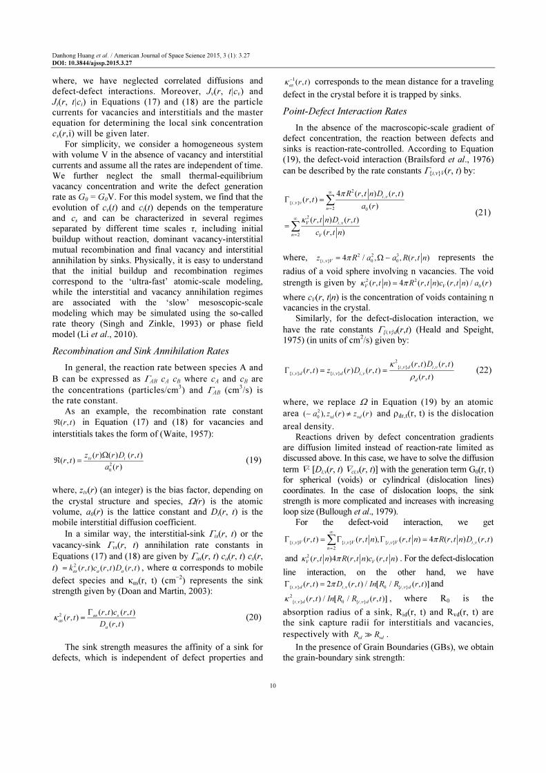
The nucleation of loops is a clustering process that
results in a critical size embryo for further growth. As an
example, by denoting the number of clusters consisting
of j vacancies as ρv(j), the master equations for ρv(j) are:
0
1
1
1 1
1
( )( ) [ ( ) ( )]
( ) ( ) ( )
1 ( ) ( ) [ ( ) ( )
[ ( ) ( )
n
n
n
n
v
nvn
j
vn
n v vn n
vn
jG j j i j
t
v j a j v j
j v j n j n j n v j n
j n v j n
ρβ β
ρ ρ
β ρ β ρ
β ρ
∞
=
=
∞
= =
∞
=
∂= − +
∂
−
+ − − − + − + +
+ +
∑
∑
∑ ∑
∑
(29)
where, βvn and βin are the capture rates of migrating
vacancy (v) or interstitial (i) clusters of size n by a
cluster of size j and ( )nv
a j is the emission rate for the new
vacancy cluster of size n by a cluster of size j. In Equation
(29), the first term is the direct production of a cluster of
size j, while the second term is the loss of clusters from size
j due to absorption of a cluster of size n. The third term is
the loss of a cluster of size j due to emission of a cluster of
size n. The fourth and fifth terms in Equation (29) are the
addition of clusters to the cluster of size j due to absorption
of vacancy clusters by a smaller cluster and absorption of
interstitial clusters by a larger cluster and the last term is the
addition of clusters to the cluster of size j due to loss of
vacancy clusters by a larger cluster.
Since the dominant contribution for cluster reactions
is with point defects (i.e., cluster of size j = 1), for both
vacancies and interstitials, Equation (29) with j≥2 can be
simplified to:
0
( ; )( ; ) ( 1, )
( 1; ) ( 1) ( 1; )
( , 1) ( , 1) ( ; )
j tG j t j j
t
j t a j j t
j j a j j j t
ρβ
ρ ρ
β ρ
∂= + −
∂
− + + +
− + + −
(30)
If the cluster size index j can be treated as a
continuous variable ξ, Equation (30) reduces to a
Fokker-Planck equation (Semenov and Woo, 2002).
According to Equation (30), for the dislocation loop
growth, we find the evolution of the number density ρil(j,
t) for the interstitial loop of size j satisfies:
0 4
( ; )( ; ) [ ( 1)
( 1)] ( 1; ) ( 1) ( 1; )
( ) ( ) ( ) ( ; )
j v
i il i il
v i i il
j tG j t j
t
a j j t j j t
j j a j j t
ρβ
ρ β ρ
β β ρ
≥
∂= + +
∂
+ − + + − −
− +
(31)
Where:
, , ,
( ) 2 ( ) ( ) ( , ) ( , )i v c i v i v
j r j z j D r t C r tβ π= (32)
, , ,
,
( )( , )( ) 2 ( ) ( ) exp
b i vi v
i v c
B
E jD r ta j r j z j
k Tπ
= −
Ω (33)
r(j) and zc are the radius and bias factor of an
interstitial loop of size j and Eb(j) is the binding energy
for a cluster of j defects.
The saturation of the dislocation density ρd(t) in
quasi-steady state was found experimentally to be due to
a recovery process at high temperatures, (Was, 2007)
given by:
2
2 1
( )( ) ( )d
d d
d tA t A t
dt
ρρ ρ= − (34)
where, A2 and A1 are constants. This gives the steady-
state solution 2 1/
s
dA Aρ = and the time-dependent
solution is found to be:
2
0
0
1 / (1 )( )
1 / (1 )
x s x
d dd
s x s x
d d d
e et
e e
ρ ρρ
ρ ρ ρ
− −
− −
− + + = − + +
(35)
where, 0
dρ is the initial value and
1( )
s
dx t A tρ= . In
addition, a phase field model has been developed to
describe the growth kinetics of interstitial loops in
irradiated materials during aging. The diffusion of
vacancies and interstitials and the elastic interaction
between interstitial loops and point defects are accounted
for in this model. The effects of interstitial concentration,
chemical potential and elastic interaction on the growth
kinetics and stability of interstitial loops are investigated
in two and three dimensions. The elastic interaction
enhances the growth kinetics of interstitial loops. The
elastic interaction also affects the stability of a small
interstitial loop adjacent to a larger loop. The linear
growth rates for interstitial loops predicted is in
agreement with the previous theoretical predictions and
experimental observations (Hu et al., 2012).
Spherical Neutral Void Growth
Not all the defects generated by radiation-induced atom displacement are point defects. Some of the defects form clusters and the vacancy clusters may further grow to form voids. For a small number of vacancies, the

Danhong Huang et al. / American Journal of Space Science 2015, 3 (1): 3.27
DOI: 10.3844/ajssp.2015.3.27
13
spherical void is favorable, while for a large number of vacancies, the planar loop is a more stable configuration.
The dynamics for void growth is very similar to that
for dislocation-loop growth. The net absorption rate of
vacancies by a spherical void is the difference of
absorption rates of vacancies and interstitials, i.e.,
4 [ ( )] V
net V v v v i iA R D V C R D Cπ= − − . Therefore, the
equation for the growth of a spherical void of radius
RV(t) (or volume) in quasi-steady state is:
( ) ( , )[ ( , )
( )
( )] ( , ) ( , )
V
v v
V
v V i i
dR tD r t c r t
dt R t
c R D r t c r t
Ω=
− −
(36)
where, cv(RV) is the vacancy concentration at the void
surface.
From the balance equation, we get the concentrations
of point vacancies and interstitials as follows:
2
, ,
,
( , ) ( , )( , ) 1 1
2 ( , )
i v i v
i v
D r t k r tc r t
R r tη = + − (37)
where,2 2 2
, , 0( , ) ( ) ( , ) 4 ( , ) ( , ), 4 /
i v i v d V V i v v ik r t z r r t R r t c r t RG D D k kρ π η= + =
. Inserting Equation (37) into Equation (36), we obtain:
0( ) ( ) 2 ( )
1 1V thdR t dR t dR t
dt dt dtη
η
= + − −
(38)
where, dR0(t)/dt is proportional to (zi − zv) G0 and
independent of temperature, while the second negative
term represents the thermal emission of defects from
sinks and strongly depends on temperature
(proportional to eq
v vD C ).
Neglecting the thermal emission in Equation (38), we
get from Equation (36):
( )0
2 2
41 1
2 ,
d dV v i
i v v i
V i v v i
dR D D RGd z z z z
dt R R D D k kρ
Ω≈ + − −
(39)
where, the sign of the bias of dislocation ( )d d
i v v iz z z z− for
vacancies and interstitials determines the occurrence of
either growth (dRV/dt > 0) or shrinkage (dRV/dt < 0). It
should be noted that void growth in materials under
radiation has been recently studied by the phase field
model, (Li et al., 2010) which provides important
insights into the growth kinetics of voids. The model
takes into account the generation of vacancies and
interstitials associated with the irradiation damage, the
recombination between vacancies and interstitials, defect
diffusion and defect sinks. The results demonstrate that
the temperature gradient causes void migration and
defect fluxes, i.e., the Soret effect, which affects void
stability and growth kinetics. It is found that the effect of
defect concentration, generation rate and recombination
rate on void mobility for migration is minor although
they strongly influence the void growth kinetics.
Radiation Degradation of Electronic Devices
Let us consider a commonly used layered-structure
material, (Huang and Zhou, 1988) as shown in Fig. 3.
Each material layer is characterized by the radiation
parameters Gj, jℜ , Dj and Γj with j = 1, 2, 3, 4 for
generation and recombination rates, diffusion coefficient
and bulk-sink annihilation, which will be employed to
model the dynamics from an ultra-fast atomic-scale up to
100 ns. The calculated non-steady state defect
distribution in each layer will be used for initial conditions
in a slow mesoscopic-scale diffusion and annihilation
model in order to calculate the steady-state spatial
distribution of defects in the whole layered structure. In
modeling the mesoscopic-scale, the interface-sink strengths 2
ik with i = 1, 2, 3 will also be considered. Once the steady-
state distribution of point defects, denoted as ρd(z), is
obtained for the whole layered structure, they will be fed
into the follow-up calculations for radiation degradation in
electronic devices, as described below.
The band structure of a crystal largely determines the
properties of electrons, (Gumbs and Huang, 2013) such
as effective mass, bandgap energy, density of states,
plasma frequency and absorption coefficient. These
electron properties are a result of the unique crystal
potential from all lattice atoms, instead of properties
of an individual lattice atom. On the other hand, the
radiation-induced displacements of lattice atoms are
determined not only by the intrinsic properties, such
as mass of the atoms, but also by the extrinsic
conditions, such as kinetic energy of incident particles
and lattice temperature.
Steady-State Defect Distributions
For the reaction rate control system shown in Fig. 3, by generalizing Equations (17) and (18), we write down the diffusion equations for point vacancies and interstitials as:
2
02
2
0
2
2 0
1 1 1 1
2
( , ) ( , )( )
( , )[ ( , ) ( )]( )
4 [ ( ) ]( , )[ ( , ) ( )]
( ) ( , ) ( 1)
j jj jv vv
j j
iv j i j j eq
i v vj
j j
V v j j eq
V v vjn
j j j j eq
vd d v v v
n
c z t c z tD G t
t z
z Dc z t c z t c j
a
R t n Dc z t n c z t c j
a
z t n D c z t c j
π
ρ
∞
=
∞
+ + + +
=
∂ ∂= +
∂ ∂
Ω− −
− −
− − +
∑
∑1
0 1( )j
ja z zδ+
+−

Danhong Huang et al. / American Journal of Space Science 2015, 3 (1): 3.27
DOI: 10.3844/ajssp.2015.3.27
14
Fig. 3. Layered-structure material with radiation parameters Gj,
Rj, Dj and Γj (j = 1, 2, 3, 4) for generation,
recombination, diffusion coefficient and bulk-sink
annihilation, respectively. In addition, 2
ik for i = 1, 2, 3
represents the interface-sink strengths. Particles are
incident from the front surface at z = 0 and exit from the
back surface at z = z4
0
2
2
02
2
0
2
1
2 0
1 1
( ) [ ( , ) ( ) ( )],
( , ) ( , )( )
( , )[ ( , ) ( )]( )
4 [ ( )]( ) ( , )
(
j j j j eq j
vd d v v v j
n
j jj jv ii
j j
iv j i j j eq
i v vj
j
V j j
v ijn
j j
id d
z t n D c z t c j a z z
c z t c z tD G t
t z
z Dc z t c z t c j
a
R t nc t n c z t
a
z t
ρ δ
π
ρ
∞
=
∞
+
=
+ +
− − −
∂ ∂= +
∂ ∂
Ω− −
−
−
∑
∑
1 1 1
0 1
2
) ( , ) ( )j j j
i i j
n
n D c z t a z zδ∞
+ + +
+
=
− ∑
(40)
0
2
( ) ( , ) ( )j j j j j
vd d i i j
n
z t n D c z t a z zρ δ∞
=
− − ∑ (41)
where, the integer j is the layer index, zj-1 and zj
represent the left and right interface positions of the
jth layer, respectively. In Equations (40) and (41), we
used the facts that 2 2 2
, , , 0 0/ , 4 /
i v i v i v V V Vz D a R c aκ πΓ = Ω =
and 2
, , i v d i vz d dκ ρ= for a reaction rate control system.
The diffusion coefficients ,
j
i vD for point vacancies
and interstitials are calculated as:
,
2
, , 0
, ,
, 0
( )( ) ( ) exp
( ) ( )exp exp
i vj j j mi v i v j
B
i v i vjm m
i v
B B
S jD T f a
k
E j ES jf D
k T k T
η ∆
=
=
(42)
where, ,
1j
i vf < is the diffusion correlation factor, ηj is the
structural factor relating to the jump distance and
number of nearest neighbors, νj is the jump frequency on
the order of the Debye frequency, , ( )i v
mS j∆ is the change
in entropy due to vibrational defect disorder and , ( )i v
mE j
is the point-defect migration energy.
The radius ( )j
VR t n of the spherical void of size n
(in unit of lattice constant) introduced in Equations
(40) and (41) is determined from the following void
growth equation:
( ) [ ( , ) ( )] ( , )
( )
j
jV j j j j j
v v v V i ij
V
dR t nD c z t c t R D c z t
dt R t n
Ω= − − (43)
where, ( )j
v Vc t R is the vacancy concentration at the void
surface and is given by:
0( ) ( )[2 / ( ) ]
( )[ ( ) 4 ( ) ( )]
j j j
v j v d j V jj
v V j j j j
B v d V V
c j z t R t nc tR
k T z t R t n c t n
ρ γ σ
ρ π
Ω −=
+ (44)
γj is the surface tension of the void, σj is the hydrostatic
stress applied to the void and 0( )vc j is the thermal-
equilibrium vacancy concentration, given by:
0
0
( )1( ) exp
( ) ( )exp ( )exp
v
f
v
j B
v v
f f
B B
S jc j
k
E j E jn j
k T k T
∆= Ω
− = −
(45)
j
fS∆ is the change of entropy for the formation of a point
vacancy and j
fE is the point vacancy formation energy.
By using a continuous variable, the void concentration
( , )j
Vc z t n ( 2)withn ≥ introduced in Equations (40) and (41)
can be obtained by solving the Fokker-Planck equation in
the size space below (with ξ = n):
0
( , )( )
( , ) ( , ) ( , ) ( , )
j
V j
j j
j V j V
c z tG t
t
F z t c z t D z t c z t
ξξ
ξ
ξ ξ ξ ξξ
∂ ∂= −
∂ ∂
∂ − ∂
(46)
where, ( , ) ( , ) ( , )j j j j j j
j v v v i i iF z t z D c z t z D c z tξ = − is the drift
term, ( , ) [ ( , ) ( , )] / 2j j j j j j
j v v v i i iD z t z D c z t z D c z tξ = + is the
positive diffusion term and 0( )j
G t ξ is the cluster
production rate per volume (with ζ ≥ 2).
Finally, the dislocation-loop density ( )j
d t nρ introduced
in Equations (40) and (41) can be found from (with n ≥ 4):
0
( 1)( )( , )
( , 1) ( 1)
( , 1) ( 1 [ ( , )
( , ) ( , ) ( ])
jjvd
j j j
i j d
j j j
i j d v j
j
i j i j d
t nt nG z t n
t a z t n t n
z t n t n z t n
z t n a z t n t n
βρ
ρ
β ρ β
β ρ
+∂= +
∂ + + +
+ − − −
+ +
(47)

Danhong Huang et al. / American Journal of Space Science 2015, 3 (1): 3.27
DOI: 10.3844/ajssp.2015.3.27
15
where, G0(zj, t|n) is the production rate per unit volume
for the interstitial dislocation loop of length n, the
absorption (βi,v) and emission (αi,v) rates in Equation (47)
are defined by:
, , ,
( , ) 2 ( ) ( ) ( , )j j j j
i v j j c i v i v jz t n n z n D c z tβ ρ= ℓ (48)
, , ,
,
( )( , ) 2 ( ) ( ) exp
jj
b i vi vj j
i v j j c
j B
E nDa z t n n z n
k Tπ
= −
Ω ℓ (49)
( ) ( )j
j cn and z nℓ are the radius and bias factor of an
interstitial loop of size n and ( )j
bE n is the binding energy
for a cluster of n interstitial atoms.
The initial condition for the diffusion equations will
be given by the corresponding calculated results from the
atomic-scale model for individual layers. The point
defect diffusion occurs mainly around interfaces between
two adjacent layers or across the interfaces. The
boundary conditions with continuous concentrations of
point defects, as well as the jump in their derivatives
determined by the dislocation sinks, will be applied at
each interface. In addition, the constraints for the zero
concentration of point defects as well as the zero
derivative of the concentration with respect to z at the
two surfaces of the system will be enforced in our
numerical computations.
Point-Defect Electronic States
To study the defect degradation effect on devices, we
need to know not only the concentration and spatial
distribution ρd(r) of the irradiation-induced defects but
also their electronic properties, such as energy level Ej,
wave function ψj(r) and local density of states Dd(r, E).
Although the semi-classical MD calculation and the
reaction-rate theory allow us to obtain the concentration
and spatial distribution of defects, we still require
Density-Functional Theory (Drabold and Estreicher,
2007; Freysoldt et al., 2014) (DFT) for calculating defect
configurations, energy levels, density of states and
charge trapping by point defects in crystals.
The main idea of DFT is to reformulate the energy
of an atomic system as a functional of the ground state
electron density function ρ0(r) instead of individual
electron wave functions. The proof of existence of such
a functional relies on a one-to-one correspondence
between the external potential Vext(Rℓ, rm) and
ρ0(r), where Rℓ and rm label all the lattice atoms
and electrons, respectively. The mapping of Vext(Rℓ,
rm) onto ρ0(r) is obvious. Any Hamiltonian H
with a
given external potential Vext(Rℓ, rm) has a ground
state solution with an N-electron wave function
ϕ0(rm), which can be uniquely associated with the
electron density function ρ0(r) using:
23 3 3
0 0 1 2 1 1 2( ) ... ( , ,..., ) ( ) ...
N Nr Nf f r r r r r d r d r d rρ ϕ δ= − (50)
Due to the resulting one-to-one correspondence
between Vext(Rℓ, rm) and ρ0(r), the energy Ei of the
atomic system can be expressed as a functional of the
electron density ρ0(r). The many-electron wave function
of ϕ(r1, r2,…, rN) depends on the ‘combination’ of all
spatial electron coordinates. Unfortunately, such an
approach would by far exceed any computational
capabilities. However, this problem can be overcome by
using the Kohn-Sham (KS) ansatz, (Kohn and Sham,
1965) in which the fully-interacting system is replaced
by a non-interacting one. This approach corresponds to a
mean-field approach, where the many-electron wave
function is decomposed into a product of N single-
electron orbitals φi(r) (i.e., Slater determinant). This
simplification leads to a neglect of an energy
contribution termed ‘correlations’. As a correction, the
functional Exc[ρ(r)] must be introduced as an additional
term in the Hamiltonian. Applying the variation principle
to the modified Hamiltonian yields a single-particle-like
Schrodinger equation, also referred to as the Kohn-Sham
equation in DFT. This equation includes an effective
potential Veff(r), which is produced by the Coulomb forces
of all other electrons and nuclei and incorporates the
exchange and correlation interactions, i.e.,:
22
( ) ( ) ( )2
KS KS KS
eff i i i
e
hV r r r
mφ ε φ
− ∇ + =
(51)
( ) ( ) ( ) [ ( )]eff ext ee xcV r V r V r V rρ= + + (52)
where, Vee(r) describes the electron-electron interaction
(the classical Coulomb interaction) that is defined by:
2
3
0
( ')( ) '
4 'ee
e rV r d r
r r
ρ
π=
∈ −∫ (53)
and Vxc[ρ(r)] is the functional derivative of the
exchange correlation energy with respect to the
electron density function:
[ ( )][ ( )]
( )
xc
ee
E rV r
r
δ ρρ
δρ= (54)
The total energy of the atomic system can be
arranged as:
[ ] [ ] [ ] [ ] [ ]k ext ee xc
E T V V Eρ ρ ρ ρ ρ= + + + (55)
where, Tk[ρ] represents the kinetic energy of non-
interacting electrons. The exchange-correlation
functional in Equation (54) can be written as:

Danhong Huang et al. / American Journal of Space Science 2015, 3 (1): 3.27
DOI: 10.3844/ajssp.2015.3.27
16
[ ] ( [ ] [ ]) ( [ ] [ ])xc k el ee
E T T V Vρ ρ ρ ρ ρ= − + − (56)
where, Vel[ρ] is non-local electron-electron interaction
beyond the classical one in Equation (53). Exc[ρ] is
simply the sum of the error made in using a non-
interacting kinetic energy and the error made in treating
the electron-electron interaction classically. The
Kohn-Sham equations in Equation (51) have the same
structure as the Hartree-Fock equations with the non-
local exchange potential replaced by the local
exchange-correlation potential Vxc[ρ(r)]. The
computational cost of solving the Kohn-Sham
equations scales formally as N3 (due to the need to
maintain the orthogonality of N orbitals), but in
current practice it drops to N through the exploitation
of the locality of the orbitals. Actually, the utility of
the theory rests on the approximation made for Exc[ρ].
Therefore, the correct description of the exchange-
correlation functional takes a crucial role in DFT. The
localdensity approximation has already achieved
satisfactory results for systems with a slowly varying
electron density function, such as metals (Kohanoff,
2006). However, it has a tendency, termed over-binding,
to overestimate binding energies and thus, for instance,
predicts too strong hydrogen bonds with too short bond
lengths. The generalized gradient approximation is a
systematic expansion, which gives good results in most
cases and corrects the issue of over-binding (Kohanoff,
2006). Recently, hybrid functionals (Alkauskas et al.,
2008) have emerged, which achieve an improved
accuracy, especially for semiconductors with a bandgap
(Broqvist et al., 2008).
Defect levels for charge capture or emission are
calculated by means of the formation energies '[ ]
q q
fE X ,
(de Walle and Neugebauer, 2004) with are defined for a
certain charge state q and a certain atomic configuration 'q
X of the defect as:
' '[ ] [ ] [ ]
( )
q q q
f tot tot
j v corr
j
E X E X E bulk
n q V Eξ µ ε
= −
− + + + ∆ +∑ (57)
Here, Etot[bulk] stands for the total energy of a super-
cell containing pure bulk material while '[ ]q
totE X
represents the super-cell containing a defect. The third
term corrects for the different numbers of atoms in
both super-cells. The integer nj stands for the number of
added (nj > 0) or removed (nj <0) atoms which are required
to create the defect from a perfect bulk structure and ξj
denotes the corresponding energy in an atomic reservoir,
which must be specified for each individual case. The
fourth term accounts for the charge state q of the
defect, in which µ is defined as the electron chemical
potential referenced with respect to the valence band
edge εν in a bulk-like region and ∆V corrects the shift
in the reference level between charged and uncharged
super-cells and is obtained from the difference in the
electrostatic potential far distant from the defect for
these two super-cells. Due to the periodic boundary
conditions, charge neutrality must be maintained within
a super-cell. Therefore, a homogeneous compensating
background charge must be introduced in calculations
of charged defects. This artificial Coulomb interaction
is corrected by the last term Ecorr.
Defect-Assisted Resonant Tunneling
At low temperatures, the defect-assisted tunneling
through thermal emission can be neglected (Huang et al.,
1999). Therefore, the whole elastic tunneling process can
be divided into two subsequent ones, i.e., tunnel
capture and tunnel emission, as shown in Fig. 4.
Although the in-plane momentum of electrons is not
conserved during the tunneling process, the kinetic
energy of electrons is conserved. For a neutral point
defect, let us assume that it sits at an arbitrary position
z = z0 inside a barrier layer (0≤z0≤LB) between the Left
(L) and Right (R) electrodes with energy levels 0 < Ed(z0)
<∆Ec, where ∆Ec is the conduction band offset for the
middle barrier layer. A bias field εb is applied across the
layer, leading to a voltage drop Vb = εbLB.
Fig. 4. Schematic of defect-assisted resonant tunneling, where a
point defect with energy E = Ed(z0) at z = z0 inside the
barrier layer with conduction-band offset ∆Ec and barrier
thickness LB. The electron from the left electrode with
Fermi distribution fL is first captured from left (process-1
in red) by the point defect through tunneling and then
emitted to a continuum state above the energy barrier on
the right (process-2 in blue) through tunneling in the
presence of a voltage drop Vb across the barrier layer
Danhong Huang et al. / American Journal of Space Science 2015, 3 (1): 3.27
DOI: 10.3844/ajssp.2015.3.27
17
By assuming a large voltage drop, we need to consider
only the forward current from left to right but not the
backward current from right to left. In this picture, the
left-going (capture) tunneling current density JL(Vb, T )
can be formally written as (Huang et al., 2008):
0 00
2
2 2
0
( , ) 2 ( )
2 /( )
[ ( )]
BL
L b d
d
k d d L k
k k d d
J V T e dz z
U F Eh E E z
ρ
π πψ
=
ΓΨ
− + Γ
∫
∑ (58)
where, ρd(z0) represents the distribution of the point-
defect concentration, Ud(r) is the Coulomb potential
associated with the point defect, ψd(r) is its wave
function and Γd is the broadening in the density of
states for point defects.
In Equation (58), the occupation factor FL(Ek) is
defined as:
(0)
0
(0)
0
( ) ( )1 [ ( )]
[1 ( )] [ ( )]
L k L k d
e L k d f
F E f E g E z
Z f E g E z Z
= −
− −
(59)
where, Ek = h2k
2/2m∗ is the electron kinetic energy with
effective mass m∗ in the left electrode, Ze and Zf
represent the structural degeneracy factors of the point
defect when empty or filled, g[Ed(z0)] is the defect
occupancy function and (0) 1
0( ) 1 exp[( ) / ]
L k k Bf E E k Tµ
−
= + − is the Fermi
distribution function in the left electrode with chemical
potential µ0. In addition, by employing the WKB
approximation (Gill, 1982) for the electron wave
function Ψk(r), the interaction matrix ⟨Ψk|Ud|ψd⟩ is
calculated as (Stievenard et al., 1992):
0
1 00
0
exp ' ( ') [ ( ), ]( )
zk
k d d
AU dz K z u K z k
K z
ψ Ψ = − ∫
(60)
where, Ak is an unknown coefficient to be determined by
the continuity of the wave function at the boundaries, S
is the cross-sectional area:
*
22
( )z
b
c
eVmK z E
LB
= ∆ −
ℏ (61)
0
1 0
1/ 2
.3 0
[ ( ), ]
( )( ) ( ) exp ' ( ')
( )
ikz
r
d dz
u K z k
eK zd r r U r dz K z
K z Sψ
− = − ∫ ∫
(62)
In a similar way, we can also calculate the right-
going (escape) tunneling current density JR(Vb, T ). In
steady state, we have JL(Vb, T ) = -JR(Vb, T ) ≡ J(Vb, T ).
This allows us to eliminate the unknown defect
occupancy function g[Ed(z0)] and eventually obtain
(Stievenard et al., 1992):
( )(0) (0)
0 00
0 0
( , ) 2
( )( ) ( )
B
b e f L R
LR L
c em
J V T eZ Z f f
dz d zP z P z
ρ
= −
Θ Θ+
∫
(63)
where, (0) 1
0( ) 1 exp[( ) / ]
R k k b Bf E E eV k Tµ
−
= + − + and (0) (0)
, , ,(1 )L R L R e L R ff Z f ZΘ = + − . In addition, the tunnel-capture
rate (probability) Pc(z0) of an electron by a point defect
in Equation (63) is defined as:
2
0 2 2
0
2 /( )
[ ( )]
d
c k d d
k k d d
P z UE E z
π πψ
Γ= Ψ
− + Γ∑
ℏ (64)
and the tunnel-emission rate (probability) Pem(z0) of
an electron captured by a strongly-localized point
defect is given by:
* 3
2 0
0*
2 0
4 2 ( )( ) exp
34 2 ( )
db
em
bd
m E zeP z
em E z
ε
ε
= −
ℏ (65)
For photo-detectors, the defect-assisted resonant
tunneling greatly increases the dark current in the
absence of incident light, which generates excess
noise and reduces the detectivity of the photo-detector
(Huang et al., 2000).
Reduced Carrier Mobility
When point defects are charged with a charge
number |Z∗| ≥ 1, they can scatter conduction electrons
through their Coulomb potential
3 ' ' ' 2
1
( ) ( )N
c d i
i
d r U r r r rψ
=
− −∑∫ , as shown in Fig. 5,
where ri for i = 1, 2,…, N represent the positions of N
point defects inside the quantum well (formed in
semiconductors by having a layer of narrow bandgap
material sandwiched between two layers of a material
with a wider bandgap to create discrete energy levels)
and ψd(r) ≡ ψd(r||) γd(z) is the wave function of the
point defect in layered semiconductors. Let us
consider electrons confined in one of the quantum
wells with width LW and barrier height ∆Ec. For
simplicity, we assume that only the ground state of
electrons is occupied at low temperatures with the
wave function .
11( ) ( )
ik r
k
er z
Sψ φ=
and subband energy
2 2 *
1 1( ) / 2E k h k mε= +
with quantum-well cross-
sectional area S, subband edge ε1 and electron
effective mass m∗.

Danhong Huang et al. / American Journal of Space Science 2015, 3 (1): 3.27
DOI: 10.3844/ajssp.2015.3.27
18
Fig. 5. Schematic of scattering of an electron by a point defect,
where the defect is charged and has an effective charge
number Z∗. The incident electron with wave vector k
and kinetic energy Ek is scattered into a different
direction with wave vector k′ and kinetic energy Ek′.
The scattering angle between k and k′ is denoted by θkk′
and the elastic scattering process requires Ek = Ek′
In this case, the interaction matrix 1 1 'ck kUΨ Ψ
is
calculated as (Huang et al., 2005a):
'1 1
2' .
1
1
( ) ( , ) ( ) ,
ck k
Niq r
c i d q
i q
U
dz z U q z z F q k k eφ δ −
=
Ψ Ψ
= − −∑∑∫
(66)
where, the two-dimensional Fourier transform of Uc(r-ri) is denoted as Uc(q||, z-zi) and give by:
2
0
' 2
*( , )
2 ( )
' ( ')i
c i
r s
q z z z
Z eU q z z
q q
dz e d zγ− − −
±− =
∈ ∈ +
∫
(67)
2
2 .( ) ( )
iq r
d dF q d r e rψ−
= ∫
(68)
and ∈r is the dielectric constant of the quantum-well host material. Moreover, qs in Equation (67) is the inverse Thomas-Fermi screening length for quantum-well electrons, given by (Huang and Manasreh, 1996):
2
1 02
0
0
( )cosh
8 2s
r B B
E keq dk k
k T k T
µ
π
∞− −
= ∈ ∈
∫
(69)
where, T is the electron temperature and µ0 is the
chemical potential of electrons in the quantum well.
Since the positions of point defects are random, by
introducing a continuous linear density distribution
ρ1d(z0) = Sρd(z0) for point defects, the interaction matrix
from Equation (66) becomes:
( )'
0
2
22 2'
1 '
0
22 ' 2
0 1 0 1/2
*1 ' ( )
2 ( )
( ) ( ) ' ( ')W
k c d
r s
L k k z z z
dLw
Z eU k F k k
k k q
dz z dz z dz e d zρ φ γ∞ − − − −
− −∞
Ψ Ψ = −
∈ ∈ − +
×∫ ∫ ∫
(70)
where, LW is the width of the quantum well. Once the
scattering matrix elements in Equation (70) are
computed, by using Fermi’s golden rule, the momentum-
relaxation time τ0 can be obtained from:
2
2 2 '
0
'
1 1
'1 1
'
1 1
2
[ ( ) ( )] 1 cos
ck k
k k
d k d k U
E k E k
τ π
δ θ
= Ψ Ψ
− −
∫ ∫
ℏ (71)
where, '|| ||k kθ represents the angle between the two in-
plane scattering wave vectors 'k and k
. By using the
momentum-relaxation τ0 in Equation (71), the mobility
µe of electrons can be simply expressed as 0
*e
e
m
τµ = .
The reduced mobility of conduction carriers by
radiation-induced point defects will directly affect the
speed of high-mobility field-effect transistors in an
integrated circuit (Ando et al., 1982).
Non-Radiative Recombination with Defects
After the electrons are photo-excited from valence band to conduction band in a semiconductor, some of these photo-electrons will be quickly captured by point defects through an inelastic scattering process, (Huang et al., 2008) as shown in Fig. 6. By including the multi-phonon emission at room temperature (Huang et al., 2005b; Ridley, 1978), in this case the capture rate is calculated as (Jim´enez-Molinos et al., 2001; Garetto et al., 2012):
22
, 0, ,
0 ,
0
, 0
0
m 21 0 , 0
1 ( )2( , )
( )[2 ( ) 1]
2
/I ( )
[ ( ) ]
e he h e h
c d e h p k HR
HR
e h
ph HR
B
d
m e h d
E zW k z U
h
E zEXP N
k T
m E z
πψ β
β
β
πξ
∞
=
− ∆= Ψ
Ω
∆× − Ω + +
Γ
Ω − ∆ + Γ∑
ℏ
ℏ
(72)
where, Ue, hp (r) represent the potentials for the
electron-phonon and hole-phonon coupling, ψd(r) is the
wave function of the point defect, Γd is the level
broadening of the defect state, , ( )e h
krΨ are the wave
functions of electrons (e) and holes (h) in a bulk, βHR is
the Huang-Ryhs factor, ,
0 0 0 0( ) ( ), ( ) ( ) ,e h e h
e G k d h d k kE z E E E z E z E z E E∆ = + − ∆ = + are
the kinetic energies of electrons and holes, EG is the
bandgap energy of the semiconductor, hΩ0 is the optical-
phonon Nph(Ω0) = [exp(hΩ0/kBT)-1]1 is the distribution
function of thermal-equilibrium phonons, T is the
temperature and Im(ξ) is the modified Bessel function of
order m with 0 0
2 ( )[ ( ) 1]HR ph phN Nξ β= Ω Ω + .

Danhong Huang et al. / American Journal of Space Science 2015, 3 (1): 3.27
DOI: 10.3844/ajssp.2015.3.27
19
Fig. 6. Schematic of non-radiative recombination of photo-
excited electrons from valence band to conduction band
with point defects, where multiple phonons are emitted
while the photo-excited electrons recombine with
localized defect states within the bandgap
The electron-phonon coupling matrix element , 2
,
e h
d e h p kUψ Ψ in Equation (72) can be evaluated by
(Huang and Alsing, 2008):
2 2
, 3 2
, , 3
1( ) ( )
(2 )
e h
d e h p k d e h pU d q B q k U qψπ
Ψ = −∫ (73)
where,
3 ( ).
( ) ( )i q k r
d dB q k d r r eψ−− = ∫ (74)
2
2 0 , 2 2
0 ,
1 1( )
2 ( )e h p
s e h
eU q
q Q V∞
Ω= −
∈ ∈ ∈ +
ℏ (75)
V is the system volume, ∈∞ and ∈s are the high-
frequency and static dielectric constants of the host
semiconductor and the inverse Thomas-Fermi
screening length Qe,h for bulk electrons and holes is
given by:
2
2 2 ,
, 0 ,2 00
,
0 ,
( )
[1 ( )]
e h
e h k e h
r B
e h
k e h
eQ dk k f E
k T
f E
µπ
µ
∞
= −
∈ ∈
− −
∫ (76)
Here, , , 1
0 , ,( ) 1 exp[( ) / ]e h e h
k e h k e h Bf E E k Tµ µ
−
− = + − is the
Fermi distribution function for thermal-equilibrium
conduction electrons and holes with chemical
potentials µe,h.
Finally, based on the given expression for , 2
,
e h
d e h p kUψ Ψ in Equations (73)-(75), the rate for the
non-radiative recombination ,
1e h
nrτ
can be explicitly
calculated from:
0 0, ,
0
1 11 ( )
( )e h e h
nr d
dz d zz
ρτ τ
=
∫ (77)
0 0 0
0 00
1 / ( ) 1 [ ( )] ( )
[ ( )] ( )1 / ( )
e
d d e e
hd f hd
z g E z Z W z
g E z Z W zz
τ
τ
−=
(78)
3
, ,
, 0 0 0 ,3( ) ( , ) ( )
(2 )
e h e h
e h c k e h
d kW z W k z f E µ
π= −∫ (79)
3 2
2
, 0 e, 0 3 2 2
0 ,
( ) ( ) ( )(2 ) ( )
e h h d
e h
d q eW z z B q k
q Qπ
= ℜ −
∈ + ∫ (80)
m 2 21 , 0 0
/I ( )
[ ( ) / ]
d
m e h dm E z
πξ
∞
=
Γ×
− ∆ Ω + Γ∑
ℏ (81)
where, ρ1d(z0) = Sρd(z0) is the linear density
distribution of point defects in a layer with the cross-
sectional area S, g[Ed(z0)] in Equation (78) is the
defect occupancy function and Ze and Zf represent the
structural degeneracy factors of 0 0 0
1 1 1
( ) ( ) ( )e h
d d dz z zτ τ τ
= =
which allows us to eliminate the unknown g[Ed(z0)]
introduced in Equation (78), similar to what we have
done in deriving Equation (63). This leads to:
0 0
0 0
0 0
1 1 11 ( )
( ) ( )
( ) ( )
e fe h
nr nr nr
e h
e e f h
Z Z dz d z
W z W z
Z W z Z W z
ρτ τ τ
= = =
+
∫ (82)
The change in the non-radiative time by point defects
in the system will reduce the quantum efficiency of
photo-excited electrons in both light-emitting diodes and
photo-detectors (Huang and Lyo, 1999).
Inelastic Light Scattering by Charged Defects
Let us choose the z direction perpendicular to the
layered material. Light is incident on the layers in the xy-
plane and scattered by charged point defects within the
layers. We consider incident light with photon energy hωi
and wave vector ki scattered inelastically by bound
electrons within point defects at ( , )j j jr r z=
for j = 1,2,….
If the scattered-light photon energy and wave vector are
Danhong Huang et al. / American Journal of Space Science 2015, 3 (1): 3.27
DOI: 10.3844/ajssp.2015.3.27
20
denoted by hωf and kf, respectively, the excitation energy
and momentum transfer to charged point defects are given
by f i q f ihw hw hw and h hk hk= − = − . We further assume
that the ground and excited state (real) wave functions of
defects are expressed as (0) (0) (0)( ) ( ) ( )d j d j d jr r r r z zψ ψ γ− = − −
and
( ) ( ) ( )( ) ( ) ( )n n n
d j d j d jr r r r z zψ ψ γ− = − −
, where n = 1, 2….
represent different excited states of a charged point
defect. The energy levels for the ground and excited
states of charged defects are separately represented by (0) ( )d jE z and ( ) ( )n
d jE z .
In a standard way, the differential scattering cross
section 2
( , )
q
d q w
dwd
σ
Ω for inelastic light scattering can be
shown to be (Zhang et al., 1991):
22 2
2
2
0
0 0 ' 0 ' 0
, '
( ) 1( , ).
4 *
1 ( ) Im ( , ) ( , )
phii f
q f
nn z nn
n n
Nd q w ee e
dwd m c
dz d z A q q z Q q z
ωω ω
π ω π
ρ ω
+ = Ω ∈
×
∑∫
ℏ
(83)
where, ( , )z
q q q=
, ei and ef are the unit polarization
vectors for the incident and scattered light, Nph(w) =
[exp(hw/kBT) -1]−1 is the photon distribution function, T
is the temperature, Ωq represents the solid angle in three-
dimensional q-space and ρ1d(z0) is the linear density of
charged point defects.
In addition, the form factor ' 0( , )
nn zA q q z
introduced
in Equation (83) is calculated as:
'
2 0
' 0
.( )2 2 ' ( ) ( ') ' (0) '
( ')( ) (0) ( ') (0)
( , )
( ) ( ) ( )
' ( ) ( ) ( ') ( ')
z
z
iq z
nn z
iq r rn n
d d d
iq z zn n
d d d d
A q q z e
d r d r r e r r
dz dz z z e z z
ψ ψ ψ
γ γ γ γ
−
−
− +
=
×
∫ ∫
∫ ∫
(84)
The interacting density-density correlation function
' 0( , )nnQ q w z employed in Equation (83) is:
1 (0)
' 0 m ' 0( , ) ( , ) ,( )nn nm n
m
Q q z q zω ω ω−
= ∈ Π∑ (85)
where, 1 ( , )nm
q w−
∈ represents the matrix element of the
inverse dielectric function of the host material
containing defects. In addition, (0)
m ' 0( )n
zωΠ in Equation
(85) is the non-interacting density-density correlation
function, given by:
(0) ( ) (0)
0 0 0(0)
' 0 ',0 2( ) (0) 2
0 0
2 ( )[ ( ) ( )]( )
( ) ( ) ( )
n
d d d
nn nn
d d d
n T z E z E z
z
E z E z i
ω δ
ω ω
−Π =
− − + Γ ℏ
(86)
where, we assume that only the ground state of charged
point defects is occupied with the thermal occupation
factor (0)
0( )dn T z .
If there exist conduction electrons, in addition to
bound electrons in charged point defects, with
concentration n0, effective mass m∗ and homogeneous
broadening γe in the host material containing generated
point defects, the matrix elements of the dielectric
function are found to be (Huang et al., 2006):
2
, 2 2( , ) 1
( ) 3 / 5
p
nm m n
e F
q wi q
δω ω γ υ
Ω∈ = −
+ − (87)
where, υF = (h/m*)(3 π2
n0)1/3 is the Fermi velocity of
conduction electrons at zero temperature, Ωp =
(n0e2/∈0∈b*)
1/2 is the plasma frequency and ∈b is the
dielectric constant of the host material. Furthermore, if the host material is a doped polar
semiconductor, its optical phonon modes can couple to conduction electrons. In this case, the matrix elements of the dielectric function in Equation (87) are modified to (Huang and Zhou, 1988):
2
2
,2
2 2
( )1
( )( , )
( ) 3 / 5
p TO
p LO
nm m n
p
e F
i
iq
i q
ω ω γ
ω ω γω δ
ω ω γ υ
+ −Ω−
+ −Ω ∈ → Ω
+ −
(88)
where, the static dielectric constant ∈b in the expression for Ωp should be replaced with the optical-frequency one ∈∞, ΩLO and ΩTO are the frequencies of the longitudinal and transverse optical phonon modes and γp represents the phonon homogeneous broadening.
The inelastic-light scattering technique can be used
for identifying the charged point-defect species and their
electronic properties, (Platzman and Wolff, 1973) such
as level separation between ground and excited states,
broadening in the defect density of states and optical
polarization properties of point defects. If the incident
coherent light is provided by a pulsed laser, the ultra-fast
dynamics of charged point defects can be directly
measured and analyzed (Tsen et al., 2001).
Application of Defect Theory
Infrared imaging from space typically places the most stringent performance requirements on the hybridized Focal Plane Array (FPA) due to the additional cost, complexity and remoteness the space environment imparts as well as the 3-5 times smaller incident optical flux levels that occur in strategic environments compared to tactical (terrestrial) environments. Space also places the additional, specifically unique, requirement of radiation tolerance or rad-hardness on both elements of the FPA, the Si-CMOS (complementary metal-oxide-

Danhong Huang et al. / American Journal of Space Science 2015, 3 (1): 3.27
DOI: 10.3844/ajssp.2015.3.27
21
semiconductor) Read-Out Integrated Circuit (ROIC) and the detector array. FPAs developed for imaging applications in a space environment are meticulously characterized to evaluate their sensitivity, uniformity, operability and radiation hardness. Infrared (IR) hybrid detector arrays operated in the space environment may be subjected to a variety of radiation sources while in orbit. This means IR detectors intended for applications such as space-based surveillance or space-situational awareness must not only have high performance (high quantum efficiency and low dark current density), but also their radiation tolerance, or ability to withstand the effects of the radiation they would expect to encounter in a given orbit, must also be characterized.
Pursuit of these performance metrics are intended to enhance technology development in multispectral sensors, higher pixel sensitivities, larger array formats with higher pixel densities, higher operating temperatures, simplified manufacturing techniques and reduced costs. Specific to space applications, as described above, is radiation hardness or tolerance, which is required to mitigate detrimental effects on IR detectors exposed to energetic charged particles (mostly electrons and protons and some heavy ions) confined by the earth’s magnetic field (the van Allen radiation belts), galactic cosmic ray particles (which can be a range of elements or electromagnetic radiation) and particles, protons and heavy ions from solar flares. Detector technologies that operate in the harsh radiation environment of space with better radiation tolerance afford greater flexibility in orbit selection, technical applications and system sustainability and thus, are of more value to the space-based sensing community.
While specific mission requirements for rad-hardness vary, the effects of proton interactions with hybrid detector arrays tend to dominate in space. Thus, a specific detector’s degree of radiation tolerance is typically first characterized by measuring its performance degradation as a function of proton irradiation fluence (Hubbs et al., 2007). Subjecting IR detectors to protons will lead to two distinct damage mechanisms, ionization damage and displacement damage, which are expected to account for the performance degradation due to irradiation that will occur in optical sensors in satellites. Ionization damage, or so-called Total Ionizing Dose (TID), effects occur as the incoming particles incident on the FPA give up their kinetic energy to ionizing additional electron-hole pairs within both the detector material and the CMOS silicon of the ROIC. Some of these excess carriers can become trapped in surface states and defect levels of the dielectric materials used for passivation and as gate oxide layers. These surface states and defect levels are to be determined with the theoretical approach presented in this study. The excess trapped charge manifests in flat-band voltage shifts of the ROIC’s MOSFETs (metal-oxide-semiconductor field-effect transistors) and excess leakage currents in the detector pixels, typically surface-
currents. Displacement damage results when the incoming particle’s energy is lost to elastic or inelastic Coulomb scattering with an atomic nucleus that is sufficient to knock the atom from its lattice site and generate a vacancy-interstitial pair. The defect complexes so formed can act as electrically active sites where electron-hole recombination might occur (Claeys and Simoen, 2013). The additional defect generation thus shortens the detector material’s minority carrier recombination lifetime, resulting in increased dark current, decreased responsivity and overall degraded uniformity.
Radiation tolerance characterization typically
includes determining the rate of performance degradation via a damage factor analysis (Cowan et al.,
2012; Morath et al., 2015). The degradation rates of each
measured parameter of the detector’s performance [dark current-including the diffusion-limited, Shockley-Reed-
Hall (SRH) generation-recombination and trap-assisted tunneling mechanisms; lateral optical collection length
or effective diffusion length-and thus minority-carrier recombination lifetime and mobility; quantum efficiency;
etc.] are determined by plotting them as a function of the
proton irradiation fluence ΦP and characterizing the changes. When the change in parameter X appears
roughly linear with ΦP, which may be true on average or for only a certain fluence range, then a damage factor, KX,
can be defined such that X = X0±KX ΦP, where X0 is the
un-irradiated value of the performance parameter and the ± is determined by the expected change, e.g., + for dark
current (Fig. 7) and −for quantum efficiency (Fig. 8). Damage factors are assumed to be related only to
changes due to the effects of displacement damage, not ionization damage and are dependent on the proton
energy E (Claeys and Simoen, 2013).
The radiation-induced defects can manifest in lower
quantum efficiency (η) and higher dark current density [JD
which is related to the tunneling current density in Equation
(63)], due to the consequent reduction in minority carrier
recombination lifetime [τR which is related to the non-
radiative recombination time τnr in Equation (77)] and
increase in SRH generation-recombination, carrier diffusion
and trap-assisted tunneling. Thus, a substantial reduction in
overall detector sensitivity, or “detectivity” (D*), is
expected. Radiation tolerance can be characterized from
performance measurements taken versus fluence by
calculating the above-described damage factor (KX) or the
rate of degradation for each performance metric X (e.g., X
= η, 1/τR, JD, D*, etc). For comparison purposes, it is worth
noting that damage factors are specific to the particle type
and energy of the incoming radiation. With a known
energydependence, KX(E), predictions of the expected on-
orbit degradation ∆X ideally become possible, according to:
2
1
( )( )
E
p
X
E
d EX dE K E
dE
Φ∆ = ∫ (89)

Danhong Huang et al. / American Journal of Space Science 2015, 3 (1): 3.27
DOI: 10.3844/ajssp.2015.3.27
22
Fig. 7. Dark current (JD) as a function of proton fluence. Dashed line gives a + slope for the trend, indicating the dark current damage factor
Fig. 8. Quantum efficiency as a function of proton fluence. Dashed line gives a-slope for the trend, indicating the quantum efficiency
damage factor
where, dΦP(E)/dE is the expected orbit’s differential proton fluence spectrum (Hubbs et al., 2007).
Comparing damage factors from different detectors may allow for the more rad-tolerant detectors to be determined (as long as several other conditions that may impact damage formation are kept constant). A connection between the damage factor and the amount of displacement damage can be established by first assuming a linear increase in the defect concentration NT [related to the point vacancy concentration cv introduced
in Equation (40)] with ΦP (which the data in (Hubbs et al., 2007; Cowan et al., 2012; Morath et al., 2015) support for the fluence ranges of interest). When dominated by SRH recombination, the minority carrier recombination lifetime τR, assuming a single active recombination level, is given by:
1( )T p th
R
N vστ
= Φ (90)

Danhong Huang et al. / American Journal of Space Science 2015, 3 (1): 3.27
DOI: 10.3844/ajssp.2015.3.27
23
where, σ is the capture cross-section and νth is the
carrier thermal velocity. With these assumptions in
mind, the minority carrier recombination lifetime
must depend on ΦP according to:
1/
1 1R p
R Ro
Kτ
τ τ
= + Φ (91)
where, 1/τR0 = NT(0) σ νth. Based on the assumptions
above and from Equations (90) and (91), a material’s
defect introduction rate is thus given by:
1/
( ) 1T p
R
p th
dNK
d vτ
σ
Φ=
Φ (92)
Which means that if σνth is fairly constant, as expected
for the fluence ranges of interest, K1/τR is a relative
measure of dNT/dΦP, which is a true measure of a
device’s defect tolerance. Thus, Equation (92) suggests
that if the various performance damage factors (for
diffusion-limited or SRH or trap-assisted tunneling dark
current densities, lateral optical collection length,
quantum efficiency, etc.), can be directly related to K1/τR,
then an understanding of how they might relate to
dNT/dΦP and, furthermore, to each other, can be
determined (Morath et al., 2015). The theory presented
in this study will be used to determine the formation and
dynamics of the proton-induced defect concentration and
defect introduction rate that produce the damage factors
that describe the degradation of sensor performance
parameters. The experimentally observed increase of
photo-detector dark current and decrease of quantum
efficiency can be explained by defect-assisted tunneling and
defect-induced capture models in Section IV, respectively.
Conclusion
In conclusion, we have proposed a multi-timescale microscopic model for fully characterizing the performance degradation of electronic and optoelectronic devices. In order to reach this goal, we will employ realistic interatomic potentials in a molecular-dynamics simulation for both the ultra-fast displacement cascade stage and the intermediate defect stabilization and cluster formation stage. This simulation will then be combined with a rate-diffusion theory for the slow defect reaction and migration stage. Additionally, with assistance from a density-functional theory for identifying defect species and their electronic properties, the calculated steady-state spatial distributions of defects and clusters will be used to study and understand the physical mechanisms that degrade electronic and optoelectronic devices, including defect-assisted resonant tunneling, reduced carrier mobility, non-radiative recombination with defects and inelastic light scattering by charged defects.
In this study, we have discussed several techniques
for defect characterization. However, there are many
other approaches for characterizing defect effects. These
include electrical characterization techniques, such as
deep-level transient spectroscopy and
capacitancevoltage profiling and optical
characterization techniques, such as cathode-
luminescence and reflectance modulation. Physical and
chemical characterization techniques can also be
applied, including electron energy loss spectroscopy,
(Gumbs and Horing, 1991) secondary ion mass
spectrometry (Zhang et al., 2014) and chemical milling.
The molecular dynamics model presented in this
study can be combined with a space-weather forecast
model (Moldwin, 2008; Cooke and Katz, 1988) which
predicts spatial-temporal fluxes and particle velocity
distributions. With this combination of theories, the
predicted irradiation conditions for particular satellite
orbits allow electronic and optoelectronic devices to be
specifically designed for operation in space with
radiation-hardening techniques (such as self-healing and
mitigation). This approach will effectively extend the
lifetime of satellite onboard electronic and optoelectronic
devices in nonbenign orbits and greatly reduce the cost.
In addition, by improving the physical model for
scintillation detectors, the accuracy of space-weather
measurements will be enhanced.
Acknowledgment
Authors would like to thank the Chief Scientist of the
Space Vehicles Directorate of the Air Force Research
Laboratory for seed funding of this research effort.
Author’s Contributions
Danhong Huang: Participated substantially in the
theory of entire paper, as well as the writing/editing of
the entire paper.
Fei Gao: Participated substantially in the theory and
writing/editing of the sections entitled: “Introduction,”
“Model and Theory,” and “Sink Dynamics”.
D.A. Cardimona: Participated substantially in the
section entitled “Application of Defect Theory” and in
editing the entire paper.
C.P. Morath: Participated substantially in the theory
and experiments in the section entitled “Application of
Defect Theory.”
V.M. Cowan: Participated substantially in the
experiments in the section entitled “Application of
Defect Theory.”
Ethics
This article is original and contains unpublished
material. The corresponding author confirms that all of

Danhong Huang et al. / American Journal of Space Science 2015, 3 (1): 3.27
DOI: 10.3844/ajssp.2015.3.27
24
the other authors have read and approved the manuscript
and no ethical issues involved.
Reference
Abrahamson, A.A., 1969. Born-Mayer-type interatomic
potential for neutral ground-state atoms with Z = 2
to Z = 105. Phys. Rev., 178: 76-76.
DOI: 10.1103/PhysRev.178.76
Alkauskas, A., P. Broqvist and A. Pasquarello, 2008.
Charge state of the O2 molecule during silicon
oxidation through hybrid functional calculations.
Phys. Rev. B, 78: 161305-161305.
DOI: 10.1103/PhysRevB.78.161305
Allen, M.P. and D.J. Tildesley, 1987. Computer
Simulation of Liquids. Clarendon, Oxford.
Ando, T., A.B. Fowler and F. Stern, 1982. Electronic
properties of two-dimensional systems. Rev. Mod.
Phys., 54: 437-437.
DOI: 10.1103/RevModPhys.54.437
Brailsford, A.D., R. Bullough and M.R. Hayns, 1976.
Point defect sink strengths and void-swelling. J.
Nucl. Mater., 60: 246-256. DOI: 10.1016/0022-3115(76)90139-2
Broqvist, P., A. Alkauskas and A. Pasquarello, 2008.
Band alignments and defect levels in SiHfO2 gate
stacks: Oxygen vacancy and Fermi-level pinning.
Appl. Phys. Lett., 92: 132911-132911.
Bullough, B., M.R. Hayns and C.H. Woo, 1979. The
sink strengths of dislocation loops and their growth
in irradiated materials. J. Nucl. Mater., 84: 93-100.
DOI: 10.1016/0022-3115(79)90152-1 Callaway, J., 1991. Quantum Theory of the Solid State.
Academic Press, Inc., New York.
Claeys, C. and E. Simoen, 2013. Radiation Effects in
Advanced Semiconductor Materials and Devices.
1st Edn., Springer Science and Business Media,
Berlin, ISBN-10: 3662049740, pp: 404.
Colubov, S.I., B.N. Singh and H. Trinkaus, 2000. Defect
accumulation in FCC and BCC metals and alloys
under cascade damage conditions-Towards a
generalisation of the production bias model. J. Nucl.
Mater., 276: 78-89.
DOI: 10.1016/S0022-3115(99)00171-3
Cooke, D.L. and I. Katz, 1988. Ionization-induced
instability in an electron-collecting sheath. J.
Spacecraft and Rockets, 25: 132-138.
DOI: 10.2514/3.25961
Cowan, V.M., C.P. Morath, J.E. Hubbs, S. Myers and E.
Plis et al., 2012. Radiation tolerance
characterization of dual band InAs/GaSb type-II
strain-layer superlattice pBp detectors using 63MeV
protons. Appl. Phys. Lett., 101: 251108-251108.
DOI: 10.1063/1.4772543
de Walle, C.G.V. and J. Neugebauer, 2004. First-principles
calculations for defects and impurities: Applications to
III-nitrides. J. Appl. Phys., 95: 3851-3851.
DOI: 10.1063/1.1682673
Devanathan, R., T. Diaz de la Rubia and W.J. Weber,
1998. Displacement threshold energies in β-SiC. J. Nucl. Mater., 235: 47-52.
DOI: 10.1016/S0022-3115(97)00304-8
Devanathan, R., W.J. Weber and F. Gao, 2001. Atomic
scale simulation of defect production in irradiated
3C-SiC. J. Appl. Phys., 90: 2303-2303.
DOI: 10.1063/1.1389523 Doan, N.V. and G. Martin, 2003. Elimination of
irradiation point defects in crystalline solids: Sink strengths. Phys. Rev. B, 67: 134107-134107.
DOI: 10.1103/PhysRevB.67.134107
Drabold, D.A. and S.K. Estreicher, 2007. Theory of
Defects in Semiconductors. Springer-Verlag,
Berlin, Heidelberg.
Finnis, M.W. and J.E. Sinclair, 1984. A simple empirical
N-body potential for transition metals. Phil. Mag. A,
50: 45-55. DOI: 10.1080/01418618408244210
Frenkel, D. and B. Smit, 2002. Understanding Molecular
Simulation: From Algorithms to Applications. 1st
Edn., Academic Press, San Diego,
ISBN-10: 0122673514. pp: 638. Freysoldt, C., B. Grabowski, T. Hickel and J.
Neugebauer, 2014. First-principles calculations for point defects in solids. Rev. Mod. Phys., 86: 253-253. DOI: 10.1103/RevModPhys.86.253
Gao, F. and W.J. Weber, 2000. Atomic-scale simulation
of 50 keV Si displacement cascades in β-SiC. Phys. Rev. B, 63: 054101-054101.
DOI: 10.1103/PhysRevB.63.054101
Gao, F. and W.J. Weber, 2003a. Atomic-scale
simulations of cascade overlap and damage
evolution in silicon carbide. J. Mater. Res., 18:
1877-1883. DOI: 10.1557/JMR.2003.0262
Gao, F. and W.J. Weber, 2003b. Recovery of close Frenkel
pairs produced by low energy recoils in SiC. J. Appl.
Phys., 94: 4348-4348. DOI: 10.1063/1.1605254
Gao, F., D. Chen, W. Hu and W.J. Weber, 2010. Energy
dissipation and defect generation in nanocrystalline
silicon carbide. Phys. Rev. B, 81: 184101-184101.
DOI: 10.1103/PhysRevB.81.184101
Gao, F., H. Xiao, X. Zu, M. POsselt and W.J. Weber,
2009. Defect-enhanced charge transfer by ion-solid
interactions in SiC using large-scale Ab initio
molecular dynamics simulations. Phys. Rev. Lett.,
103: 027405-027405. DOI: 10.1103/PhysRevLett.103.027405
Gao, F., H.Y. Xiao and W.J. Weber, 2011. Ab initio
molecular dynamics simulations of low energy recoil
events in ceramics. Nucl. Instr. Meth. Phys. Res. B,
269: 1693-1697. DOI: 10.1016/j.nimb.2011.01.131

Danhong Huang et al. / American Journal of Space Science 2015, 3 (1): 3.27
DOI: 10.3844/ajssp.2015.3.27
25
Garetto, D., Y.M. Randriamihaja, A. Zaka, D. Rideau and A. Schmid et al., 2012. Analysis of defect capture cross sections using non-radiative multiphonon-assisted trapping model. Solid-State Electr., 71: 74-74. DOI: 10.1016/j.sse.2011.10.024
Gear, C., 1971. Numerical Initial Value Problems in Ordinary Differential Equations. 1st Edn., Prentice-Hall, Englwood Cliffs, pp: 253.
Gill, A.E., 1982. Atmosphere-ocean Dynamics. 1st Edn., Academic Press, San Diego, ISBN-10: 0122835220, pp: 662.
Golubov, S.I., A.V. Barashev and R.E. Stoller, 2012.
Radiation Damage Theory, in Comprehensive
Nuclear Materials. In: Konings, R., R. Stoller, T.
Allen and S. Yamanaka (Eds.), (Elsevier Ltd.,
Amsterdam, 2012), ch. 13.
Guinan, M.W., R.N. Stuart and R.J. Borg, 1977. Fully
dynamic computer simulation of self-interstitial
diffusion in tungsten. Phys. Rev. B, 15: 699-699.
DOI: 10.1103/PhysRevB.15.699 Gumbs, G. and D.H. Huang, 2013. Properties of
Interacting Low-Dimensional Systems. 1st Edn., John Wiley and Sons, Weinheim Wiley-VCH, ISBN-10: 3527638164. pp: 392.
Gumbs, G. and N.J.M. Horing, 1991. Plasma losses by
charged particles in thin films: Effects of spatial
dispersion, phonons and magnetic field. Phys. Rev.
B, 43: 2119-2119. DOI: 10.1103/PhysRevB.43.2119
Gumbs, G., 1989. Inelastic electron scattering from the
surfaces of semiconductor multilayers: Study of
Subband structure within the quantum well. Phys.
Rev. B, 39: 5186-5186. DOI: 10.1103/PhysRevB.39.5186 Heald, P.T. and M.V. Speight, 1975. Point defect behavior
in irradiated materials. Acta Met., 23: 1389 -1389. Hirth, J.P. and J. Lothe, 1982. Theory of Dislocations.
2nd Edn., Krieger Publishing Company, Florida.
Hu, S., C.H. Henager, Y. Li, F. Gao and X. Sun et al.,
2012. Evolution kinetics of interstitial loops in
irradiated materials: A phase-field model. Modelling
Simul. Mater. Sci. Eng., 20: 015011-015011.
DOI: 10.1088/0965-0393/20/1/015011
Huang, D.H. and M.O. Manasreh, 1996. Intersubband
transitions in strained In0.07Ga0.93As/Al0.40Ga0.60As
multiple quantum wells and their application to a
two-colors photodetector. Phys. Rev. B, 54: 5620-
5620. DOI: 10.1103/PhysRevB.54.5620
Huang, D.H. and P.M. Alsing, 2008. Many-body effects on
optical carrier cooling in intrinsic semiconductors at
low lattice temperatures. Phys. Rev. B, 78: 035206-
035206. DOI: 10.1103/PhysRevB.78.035206
Huang, D.H. and S.K. Lyo, 1999. Photoluminescence
spectra of n-doped double quantum wells in a parallel
magnetic field. Phys. Rev. B, 59: 7600-7600.
DOI: 10.1103/PhysRevB.59.7600
Huang, D.H. and S.X. Zhou, 1988. Theoretical
investigation of collective excitations in HgTe/CdTe
superlattices. II. Intersubband excitation and effects of
magnetic field and electron-phonon coupling. Phys.
Rev. B, 38: 13069-13069.
DOI: 10.1103/PhysRevB.38.13069
Huang, D.H., A. Singh and D.A. Cardimona, 1999.
Effects of structural disorders on sequential
tunneling in multiple quantum wells. Phys. Lett. A,
259: 488-488. DOI: 10.1016/S0375-9601(99)00473-9
Huang, D.H., A. Singh and D.A. Cardimona, 2000.
Change of microscopic tunneling on a macroscopic
time scale: Current surge model. J. Appl. Phys., 87:
2427-2427. DOI: 10.1063/1.372196
Huang, D.H., C. Rhodes, P.M. Alsing and D.A.
Cardimona, 2006. Effects of longitudinal field on
transmitted near field in doped semi-infinite
semiconductors with a surface conducting sheet. J.
Appl. Phys., 100: 113711-113711.
DOI: 10.1063/1.2388651
Huang, D.H., G. Gumbs and M. Pepper, 2008. Effects of
inelastic capture, tunneling escape and quantum
confinement on surface acoustic wave-dragged
photocurrents in quantum wells. J. Appl. Phys., 103:
083714-083714. DOI: 10.1063/1.2890403
Huang, D.H., P.M. Alsing, T. Apostolova and D.A.
Cardimona, 2005a. Coupled energy-drift and force-
balance equations for high-field hot-carrier
transport. Phys. Rev. B, 71: 195205-195205.
DOI: 10.1103/PhysRevB.71.195205
Huang, D.H., P.M. Alsing, T. Apostolova and D.A.
Cardimona, 2005b. Effect of photon-assisted
absorption on the thermody-namics of hot electrons
interacting with an intense optical field in bulk
GaAs. Phys. Rev. B, 71: 045204-045204.
DOI: 10.1103/PhysRevB.71.045204
Hubbs, J.E., P.W. Marshall, C.J. Marshall, M.E. Gramer
and D. Maestas et al., 2007. Lateral diffusion length
changes in HgCdTe detectors in a proton
environment. IEEE Trans. Nucl. Sci., 54: 2435-2443.
DOI: 10.1109/TNS.2007.910329
Jiang, C., N. Swaminathan, J. Deng, D. Morgan and I.
Szlufarsk, 2014. Effect of grain boundary stresses
on sink strength. Mater. Res. Lett., 2: 100-106.
DOI: 10.1080/21663831.2013.871588
Jim´enez-Molinos, F., A. Palma, F. G´amiz, J. Banqueri
and J.A. Lopez-Villanueva, 2001. Physical model
for trap-assisted inelastic tunneling in metal-oxide-
semiconductor structures. J. Appl. Phys., 90: 3396-
3396. DOI: 10.1063/1.1398603
Kinchin, G.H. and R.S. Pease, 1955. The displacement
of atoms in solids by radiation. Rep. Prog. Phys., 18:
1-1. DOI: 10.1088/0034-4885/18/1/301

Danhong Huang et al. / American Journal of Space Science 2015, 3 (1): 3.27
DOI: 10.3844/ajssp.2015.3.27
26
Kohanoff, J., 2006. Electronic Structure Calculations for
Solids and Molecules. Cambridge Press.
Kohn, W. and L.J. Sham, 1965. Self-consistent equations
including exchange and correlation effects. Phys.
Rev., 140: A1133-A1133.
DOI: 10.1103/PhysRev.140.A1133
Li, Y., S. Hu, X. Sun, F. Gao and C.H. Henager et al.,
2010. Phase-field modeling of void migration and
growth kinetics in materials under irradiation and
temperature field. J. Nucl. Mater., 407: 119-125.
DOI: 10.1016/j.jnucmat.2010.09.048
Maksimov, L.A. and A.I. Ryazanov, 1980. Kinetic
equation for vacancion pores. Pore lattice as a
dissipative structure stable under irradiation
conditions. Sov. Phys. JETP, 52: 1170-1170.
Mehrer, H., 2007. Diffusion in Solids: Fundamentals,
Methods, Materials, Diffusion-Controlled Processes.
1st Edn., Springer Science and Business Media,
Berlin, ISBN-10: 354071488X. pp: 672.
Moldwin, M., 2008. An Introduction to Space Weather.
1st Edn., Cambridge University Press, New York,
ISBN-10: 1139467859.
Morath, C.P., V.M. Cowan, L.A. Treider, G. Jenkins and
J.E. Hubbs, 2015. Proton irradiation effects on the
performance of III-V-based, unipolar barrier
infrared detectors. IEEE Trans. Nucl. Sci.
Murty, K.L. and I. Charit, 2013. An Introduction to
Nuclear Materials: Fundamentals and Applications.
1st Edn., John Wiley and Sons, Weinheim,
ISBN-10: 3527412018, pp: 382.
Nord, J., K. Nordlund, J. Keinonen and K. Albe, 2003.
Molecular dynamics study of defect formation in
GaN cascades. Nucl. Instr. Meth. Phys. Res. B, 202:
93-99. DOI: 10.1016/S0168-583X(02)01839-6
Nordlund, K., J. Peltola, J. Nord, J. Keinonen and R.S.
Averback, 2001. Defect clustering during ion
irradiation of GaAs: Insight from molecular
dynamics simulations. J. Appl. Phys., 90: 1710-1710.
DOI: 10.1063/1.1384856
Norskov, J.K. and N. Lang, 1980. Effective-medium
theory of chemical binding: Application to
chemisorption. Phys. Rev. B, 21: 2131-2131.
DOI: 10.1103/PhysRevB.21.2131
Olander, D.R., 1976. Fundamental Aspects of Nuclear
Reactor Fuel Elements. 1st Edn., Technical
Information Center, Oak Ridge, ISBN-10: 0870790315, pp: 551.
Platzman, P.M. and P.A. Wolff, 1973. Waves and
Interactions in Solid State Plasmas. 1st Edn.,
Academic Press, New York, ISBN-10: 012607772X, pp: 293.
Posselt, M., F. Gao and D. Zwicker, 2005. Atomistic
study of the migration of di- and tri-interstitials in
silicon. Phys. Rev. B, 71: 245202-245202.
DOI: 10.1103/PhysRevB.71.245202
Posselt, M., F. Gao and H. Bracht, 2008. Correlation
between self-diffusion in Si and the migration
mechanisms of vacancies and self-interstitials: An
atomistic study. Phys. Rev. B, 78: 035208-
035208. DOI: 10.1103/PhysRevB.78.035208
Ridley, B.K., 1978. Multiphonon, non-radiative transition
rate for electrons in semiconductors and insulators. J.
Phys. C: Solid State Phys., 11: 2323-2323. DOI: 10.1088/0022-3719/11/11/023 Rong, Z., F. Gao and W.J. Weber, 2007. Monte Carlo
simulations of defect recovery within a 10 keV
collision cascade in 3CSiC. J. Appl. Phys., 102:
103508-103508. DOI: 10.1063/1.2812701
Rubia, T.D.D.L. and G.H. Gilmer, 1995. Structural
transformations and defect production in ion
implanted silicon: A molecular dynamics simulation
study. Phys Rev. Lett., 74: 2507-2507.
DOI: 10.1103/PhysRevLett.74.2507
Rutherford, E., 1911. The scattering of a and β particles by matter and the structure of the atom. Phil. Mag.,
21: 669-669. Semenov, A.A. and C.H. Woo, 2002. Void nucleation at
elevated temperatures under cascade-damage irradiation. Phys. Rev. B, 66: 024118-024118.
DOI: 10.1103/PhysRevB.66.024118 Sigmund, P., 2006. Particle Penetration and Radiation
Effects: General Aspects and Stopping of Swift Point Charges. 1st Edn., Springer Science and Business Media, Berlin Heidelberg,
ISBN-10: 3540317139. pp: 437. Singh, B.N. and S.J. Zinkle, 1993. Defect accumulation
in pure fcc metals in the transient regime: A review. J. Nucl. Mater., 206: 212-229.
DOI: 10.1016/0022-3115(93)90125-I Stievenard, D., X. Letartre and M. lannoo, 1992. Defect-
assisted resonant tunneling: A theoretical model. Appl. Phys. Lett., 61: 1582-1582.
DOI: 10.1063/1.107503
Strour, J.R., C.J. Marshall and P.W. Marshall, 2003.
Review of displacement damage effects in silicon
devices. IEEE Trans. Nucl. Sci., 50: 653-670.
DOI: 10.1109/TNS.2003.813197 Terentyev, D., C. Lagerstedt, P. Olsson, K. Nordlund
and J. Wallenius et al., 2006. Effect of the interatomic potential on the features of displacement cascades in α -Fe: A molecular dynamics study. J. Nucl. Mater., 351: 65-67.
DOI: 10.1016/j.jnucmat.2006.02.020 Tersoff, J., 1988. New empirical approach for the
structure and energy of covalent systems. Phys. Rev. B, 37: 6991-6991. DOI: 10.1103/PhysRevB.37.6991
Tschopp, M.A., K.N. Solanki, F. Gao, X. Sun and M.A. Khaleel et al., 2012. Probing grain boundary sink strength at the nanoscale: Energetics and length scales of vacancy and interstitial absorption by grain boundaries in α-Fe. Phys. Rev. B, 85: 064108-064108. DOI: 10.1103/PhysRevB.85.064108

Danhong Huang et al. / American Journal of Space Science 2015, 3 (1): 3.27
DOI: 10.3844/ajssp.2015.3.27
27
Tsen, K.T., R.K. Willardson and E.R. Weber, 2001. Ultrafast Physical Processes in Semiconductors. 1st Edn., Elsevier, San Diego, ISBN-10: 0080540953, pp: 468.
Tuckerman, M.E. and G.J. Martyna, 2000. Understanding modern molecular dynamics: Techniques and applications. J. Phys. Chem. B, 104: 159-159. DOI: 10.1021/jp992433y
Tuomisto, F. and I. Makkonen, 2013. Defect identification in semiconductors with positron annihilation: Experiment and theory. Rev. Mod. Phys., 85: 1583-1583.
DOI: 10.1103/RevModPhys.85.1583 Waite, T.R., 1957. Theoretical treatment of the kinetics
of diffusion-limited reactions. Phys. Rev., 107: 463-463. DOI: 10.1103/PhysRev.107.463
Was, G.S., 2007. Fundamentals of Radiation Materials Science: Metals and Alloys. 1st Edn., Springer Science and Business Media, Berlin,
ISBN-10: 3540494715. pp: 827. Weatherford, T.R. and W.T. Anderson, 2003. Historical
perspective on radiation effects in III-V devices. IEEE Trans. Nucl. Sci., 50: 704-710.
DOI: 10.1109/TNS.2003.813124
Weertman, J., 1965. The Peach-Koehler equation for the
force on a dislocation modified for hydrostatic
pressure. Phil. Mag., 11: 1217-1223.
DOI: 10.1080/14786436508224930
Wiedersich, H., P.R. Okamoto and N.Q. Lam, 1979. A
theory of radiation-induced segregation in
concentrated alloys. J. Nucl. Mater., 83: 98-108.
DOI: 10.1016/0022-3115(79)90596-8
Zhang, C., G. Gumbs and D.H. Huang, 1991. Theory
of the Raman-scattering intensity and line shape of
a quantum-dot superlattice. Phys. Rev. B, 44:
10744-10744. DOI: 10.1103/PhysRevB.44.10744
Zhang, Y., M.L. Crespillo, H. Xue, K. Jin and C.H. Chen
et al., 2014. New ion beam materials laboratory for
materials modification and irradiation effects
research. Nucl. Instr. Meth. B, 338: 19-30.
DOI: 10.1016/j.nimb.2014.07.028