Embed Size (px)
Citation preview
Multi-Technology Network Management Implementation Statement Templates and Guidelines NML-EML Interface Version 3.0
TMF 814A
Version 3.0 April 2004 TeleManagement Forum 2003


MTNM IMPLEMENTATION STATEMENT TEMPLATES AND GUIDELINES
TMF 814Av3.0 TeleManagement Forum 2003 iii
NOTICE
The TeleManagement Forum (“TM Forum”) has made every effort to ensure that the contents of this document are accurate. However, no liability is accepted for any errors or omissions or for consequences of any use made of this document.
This document is a draft working document of TM Forum and is provided to its members solely for formal comments and evaluation. It is not a Forum Approved Document and is solely circulated for the purposes of assisting TM Forum in the preparation of a final document in furtherance of the aims and mission of TM Forum. Any use of this document by the recipient is at its own risk. Under no circumstances will TM Forum be liable for direct or indirect damages or any costs or losses resulting from the use of this document by the recipient.
Members of TM Forum are granted limited copyright waiver to distribute this document within their companies. They may not make paper or electronic copies for distribution outside their companies. The only purpose of the provision of this draft document to members is for making formal comments thereon to TM Forum.
This document may involve a claim of patent rights by one or more TM Forum members, pursuant to the agreement on Intellectual Property Rights between TM Forum and its members, and by non-members of TM Forum.
Direct inquiries to the TM Forum office:
89 HEADQUARTERS PLAZA NORTH - SUITE 350
MORRISTOWN, NJ 07960 USA
Tel No. +1 973 292 1901
Fax No. +1 973 993 3131
TM Forum Web Page: www.tmforum.org

MTNM IMPLEMENTATION STATEMENT TEMPLATES AND GUIDELINES
TMF 814Av3.0 TeleManagement Forum 2003 v
ACKNOWLEDGMENTS
The Multi-Technology Network Management (MTNM) NML-EML Interface, Version 3.0 is a genuinely collaborative effort. The TeleManagement Forum would like to thank the following people for contributing their time and expertise to the production of this document. It is just not possible to recognize all the organizations and individuals that have contributed or influenced the Multi-Technology Network Management (MTNM) Implementation Statement Templates and Guidelines. We apologize to any person or organization we inadvertently missed in these acknowledgments.
Key individuals that reviewed, provided input, managed, edited and determined how to utilize inputs coming from all over the world, and really made this document happen were:
Steve Arnott, Marconi Communications
Beau Atwater, Telcordia Technologies
François Bédard, Nortel Networks
Teddy Bezoza, AT&T
Alex Bojanic, Tellabs
Harrie Buiting, Lucent Technologies
Henri Campagno, France Telecom
Lee Chow, Tellabs
Merav Cohen-Sarussi, LightScape Networks
Nigel Davis, Nortel Networks
Keith Dorking, Ciena
Shane Edmonds, Alcatel
Felix Flemisch, Siemens AG
Marianne Franklin, Lucent
Steve Fratini, Telcordia Technologies
Salim Galou, Fujitsu
Elisabetta Gardelli, Siemens Mobile Communications
CB Genrich, Hitachi
Noam Goldberg, LightScape Networks
Alison Greig, Nortel Networks
Garry Grimes, Marconi Communications
Milton Hall, Telcordia Technologies
Dragan Jovanovic, Acterna
Roshan Joyce, Fujitsu
Ralf Kimmlingen, Deutsche Telekom
Nathan Kohn, Lucent Technologies
Hing-Kam Lam, Lucent Technologies
MTNM IMPLEMENTATION STATEMENT TEMPLATES AND GUIDELINES
TMF 814Av3.0 TeleManagement Forum 2003 vi
Bertrand LeBorgne, Lucent Technologies
François Leroux, Fujitsu
Tom Ligda, Cisco Systems
Peter Litz, Siemens AG
Scott Mansfield, Marconi Communications
Andrea Mazzini, Alcatel
Srini Nangavaram, Lucent Technologies
Frank O’Rourke, Marconi Communications
Sandip Patel, Lucent Technologies
Noga Peled, LightScape Networks
Edgar Riemann, Siemens AG
Jeffrey Ross, Fujitsu
Victor Santos, Acterna
Horst Schukat, Siemens AG
Eric Seldner, Telcordia Technologies
Ajit Shah, Cisco Systems
Charles Sheridan, Nortel Networks
Sidney Shiba, Fujitsu
Graham Taylor, Nortel Networks
Wendy Teller, Tellabs
Niranjan Tripathy, Fujitsu
Alexander Tschersich, Siemens AG
Gerard Vila, Alcatel
Xuli Wu, Tellabs
Bernd Zeuner, Deutsche Telekom
Yakov Zimmerman, LightScape Networks
Although not directly used within this document, access to documentation and work from standards bodies and other forums have contributed to the evolution of the Multi-Technology Network Management (MTNM) NML-EML Interface. This access was via public information or TM Forum member knowledge. This list of standards bodies and forums is not exhaustive and does not imply review and concurrence by these organizations or their representatives. It is important however to acknowledge the work and their influence on the TeleManagement Forum work:
American National Standards Institute (ANSI)
ATM Forum
DSL Forum
European Telecommunications Standards Institute (ETSI)
Institute of Electrical and Electronics Engineers (IEEE)

MTNM IMPLEMENTATION STATEMENT TEMPLATES AND GUIDELINES
TMF 814Av3.0 TeleManagement Forum 2003 vii
International Telecommunications Union - Telecommunication Standardization Sector (ITU-T)
Internet Engineering Task Force (IETF)
Metro Ethernet Forum (MEF)
MPLS and Frame Relay Alliance
Object Management Group (OMG)
Optical Internetworking Forum (OIF)

MTNM IMPLEMENTATION STATEMENT TEMPLATES AND GUIDELINES
TMF 814Av3.0 TeleManagement Forum 2003 ix
ABOUT THIS DOCUMENT
TM Forum Documents
The Multi-Technology Network Management (MTNM) Implementation Statement Templates and Guidelines specification is being issued as Version 3.0. Version 3.0 of TMF 814A shall be considered valid until further notice by the TeleManagement Forum. At which time the TeleManagement Forum expects to update it to reflect comments from implementation experience, as well as to reflect additional member comment. This version 3.0 MTNM Implementation Statement supersedes the TMF 814A version 2.1 in its entirety.
The purpose of an Evaluation Version is to encourage input based on experience of members and the public as they begin to use the document. Following the Evaluation Period, documents that are seen to deliver value are candidates for formal approval by the TM Forum. All documents approved by the TM Forum (as well as those previously approved by the NMF) undergo a formal review and approval process.
This document will continue under formal change control. Supporting work will be issued as revisions to this document. A document of this type is a “living document,” capture and communicating current knowledge and practices. Further inputs will be made because of detailed work ongoing in the TM Forum and the industry.
This document should be read in conjunction with three other documents:
TMF513 – MTNM Business Agreement
TMF608 – MTNM Information Agreement
TMF814 – MTNM Solution Set
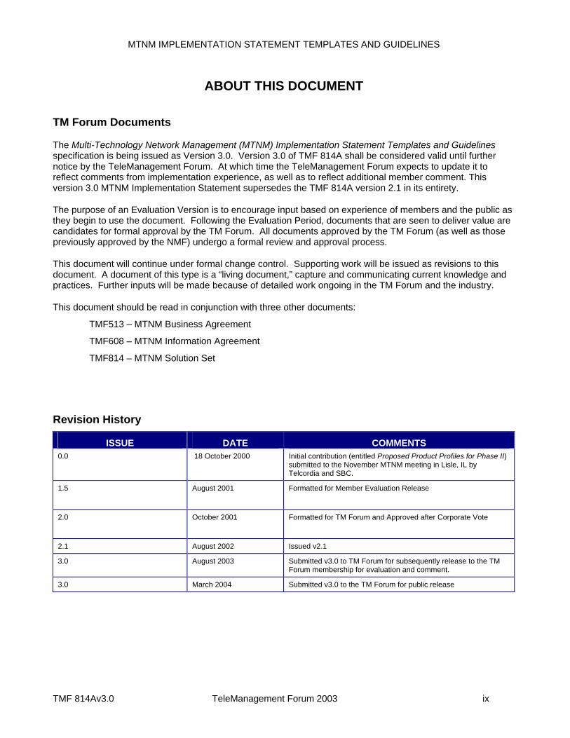
Revision History
ISSUE DATE COMMENTS 0.0 18 October 2000 Initial contribution (entitled Proposed Product Profiles for Phase II)
submitted to the November MTNM meeting in Lisle, IL by Telcordia and SBC.
1.5 August 2001 Formatted for Member Evaluation Release
2.0 October 2001 Formatted for TM Forum and Approved after Corporate Vote
2.1 August 2002 Issued v2.1
3.0 August 2003 Submitted v3.0 to TM Forum for subsequently release to the TM Forum membership for evaluation and comment.
3.0 March 2004 Submitted v3.0 to the TM Forum for public release
MTNM IMPLEMENTATION STATEMENT TEMPLATES AND GUIDELINES
TMF 814Av3.0 TeleManagement Forum 2003 x
Document Template
This document is based on Version 3.1 of the TM Forum 403, IIS Template.
Time Stamp
This version of the MTNM Implementation Statement Templates and Guidelines, TMF 814A Version 3.0, can be considered valid until further notice from TM Forum.
How can we obtain a copy?
An electronic copy of the IIS can be downloaded at the TM Forum Web Site (www.tmforum.org), Publications or through a link to Publications from a specific team’s public project area.
Depending upon the document, it could be accessible from New Items, Evaluation Versions, or a team’s Members Only project area.
If you would like a paper version of this document, please order via the TM Forum Web Site or contact the TM Forum office. If you are not a member, please contact the TM Forum office on +1 973-425-1900.
How can we comment on the documents?
Comments must be in written form and addressed to the team editor for review with the project team. Please send your comments to the editor using the editor’s e-mail shown in the section below.
MTNM Team Leader
Teddy Bezoza, AT&T
Phone : +1-732-420-1655
Fax : +1-732-368-1911
email : [email protected]
MTNM Business Agreement Editor
Keith Dorking, Ciena Corporation
Phone : +1-678-297-5007
Fax : +1-678-297 3600
email : [email protected]
MTNM Solution Set Editor
Nigel Davis, Nortel Networks
MTNM IMPLEMENTATION STATEMENT TEMPLATES AND GUIDELINES
TMF 814Av3.0 TeleManagement Forum 2003 xi
Phone : +44-1279-405978
Fax : +44-1279-405904
email : [email protected]
MTNM Information Agreement Editor
Bernd Zeuner, Deutsche Telekom
Phone : +49 61 51 / 83 - 37 09
Fax : +49 61 51 / 83 - 19 875
email : [email protected]
MTNM Implementation Statement Template and Guidelines Editor
Stephen Fratini, Telcordia Technologies, Inc.
Phone: +1-732-699-2226
Fax: +1-732-336-2423
Email: [email protected]
TMF Senior Program Support Manager
Debbie Burkett, TM Forum
Phone : +1-813-672-2698
Fax : +1-813-672-4272
email : [email protected]
MTNM email address: [email protected]

MTNM IMPLEMENTATION STATEMENT TEMPLATES AND GUIDELINES
TMF 814Av3.0 TeleManagement Forum 2003 xiii
TABLE OF CONTENTS
NOTICE ................................................................................................................................................................. III
ACKNOWLEDGMENTS.........................................................................................................................................V
ABOUT THIS DOCUMENT................................................................................................................................... IX TM Forum Documents ........................................................................................................................................ix Revision History ..................................................................................................................................................ix Document Template.............................................................................................................................................x Time Stamp..........................................................................................................................................................x How can we obtain a copy? .................................................................................................................................x How can we comment on the documents?..........................................................................................................x
TABLE OF CONTENTS......................................................................................................................................XIII
PREFACE...........................................................................................................................................................XXII About TeleManagement Forum ....................................................................................................................... xxii Use and Extension of a TM Forum Implementation Statement Template and Guidelines.............................. xxii
1 INTRODUCTION............................................................................................................................................. 1
1.1 How this document will be used .............................................................................................................. 1
1.2 Document Structure .................................................................................................................................. 1
1.3 Key terms used in this document ............................................................................................................ 2
1.4 Updates for Version 3.0............................................................................................................................. 3
2 FUNCTIONAL INTEROPERABILITY STATEMENTS (FIS) .......................................................................... 5
2.1 Overview ..................................................................................................................................................... 5 2.1.1 FIS Template ........................................................................................................................................ 5 2.1.2 Data Types ........................................................................................................................................... 5 2.1.3 Interfaces.............................................................................................................................................. 6 2.1.4 Operations ............................................................................................................................................ 7 2.1.5 Exceptions ............................................................................................................................................ 9 2.1.6 Notifications .......................................................................................................................................... 9
2.2 Alarm Severity Assignment Profile (v3.0) ............................................................................................. 13

MTNM IMPLEMENTATION STATEMENT TEMPLATES AND GUIDELINES
TMF 814Av3.0 TeleManagement Forum 2003 xiv
2.2.1 Data Types ......................................................................................................................................... 13 2.2.2 Interfaces............................................................................................................................................ 14 2.2.3 Notifications ........................................................................................................................................ 14
2.3 Common Module...................................................................................................................................... 14 2.3.1 Data Types ......................................................................................................................................... 14 2.3.2 Interfaces............................................................................................................................................ 14 2.3.3 Notifications ........................................................................................................................................ 15
2.4 EmsMgr Module ....................................................................................................................................... 15 2.4.1 Data Types ......................................................................................................................................... 15 2.4.2 Interfaces............................................................................................................................................ 15 2.4.3 Notifications ........................................................................................................................................ 17
2.5 EMS Session Module............................................................................................................................... 17 2.5.1 Data Types ......................................................................................................................................... 17 2.5.2 Interfaces............................................................................................................................................ 17 2.5.3 Notifications ........................................................................................................................................ 17
2.6 EmsSessionFactory ................................................................................................................................ 17 2.6.1 Data Types ......................................................................................................................................... 17 2.6.2 Interfaces............................................................................................................................................ 18 2.6.3 Notifications ........................................................................................................................................ 18
2.7 Equipment Module................................................................................................................................... 18 2.7.1 Data Types ......................................................................................................................................... 18 2.7.2 Interfaces............................................................................................................................................ 23 2.7.3 Notifications ........................................................................................................................................ 26
2.8 Globaldefs Module................................................................................................................................... 27 2.8.1 Data Types ......................................................................................................................................... 27 2.8.2 Interfaces............................................................................................................................................ 27 2.8.3 Notifications ........................................................................................................................................ 27
2.9 GuiCutThrough Module........................................................................................................................... 27 2.9.1 Data Types ......................................................................................................................................... 27 2.9.2 Interfaces............................................................................................................................................ 28 2.9.3 Notifications ........................................................................................................................................ 28
2.10 MaintenanceOperations Module......................................................................................................... 28 2.10.1 Data Types ......................................................................................................................................... 28 2.10.2 Interfaces............................................................................................................................................ 28
MTNM IMPLEMENTATION STATEMENT TEMPLATES AND GUIDELINES
TMF 814Av3.0 TeleManagement Forum 2003 xv
2.10.3 Notifications ........................................................................................................................................ 30
2.11 Managed Element Module ................................................................................................................... 30 2.11.1 Data Types ......................................................................................................................................... 30 2.11.2 Interfaces............................................................................................................................................ 32 2.11.3 Notifications ........................................................................................................................................ 32
2.12 ManagedElementManager Module ..................................................................................................... 32 2.12.1 Data Types ......................................................................................................................................... 32 2.12.2 Interfaces............................................................................................................................................ 32 2.12.3 Notifications ........................................................................................................................................ 36
2.13 MTNM Version Module......................................................................................................................... 36 2.13.1 Data Types ......................................................................................................................................... 36 2.13.2 Interfaces............................................................................................................................................ 36 2.13.3 Notifications ........................................................................................................................................ 36
2.14 MultiLayerSubnetwork Module........................................................................................................... 37 2.14.1 Data Types ......................................................................................................................................... 37 2.14.2 Interfaces............................................................................................................................................ 41 2.14.3 Notifications ........................................................................................................................................ 44
2.15 NMS Session Module........................................................................................................................... 44 2.15.1 Data Types ......................................................................................................................................... 44 2.15.2 Interfaces............................................................................................................................................ 44 2.15.3 Notifications ........................................................................................................................................ 45
2.16 Notifications Module............................................................................................................................ 45 2.16.1 Data Types ......................................................................................................................................... 45 2.16.2 Interfaces............................................................................................................................................ 45 2.16.3 Notifications ........................................................................................................................................ 45
2.17 Performance Module............................................................................................................................ 45 2.17.1 Data Types ......................................................................................................................................... 45 2.17.2 Interfaces............................................................................................................................................ 62 2.17.3 Notifications ........................................................................................................................................ 64
2.18 Protection Module................................................................................................................................ 64 2.18.1 Data Types ......................................................................................................................................... 64 2.18.2 Interfaces............................................................................................................................................ 66 2.18.3 Notifications ........................................................................................................................................ 67
2.19 Session Module.................................................................................................................................... 67
MTNM IMPLEMENTATION STATEMENT TEMPLATES AND GUIDELINES
TMF 814Av3.0 TeleManagement Forum 2003 xvi
2.19.1 Data Types ......................................................................................................................................... 67 2.19.2 Interfaces............................................................................................................................................ 67 2.19.3 Notifications ........................................................................................................................................ 67
2.20 SoftwareAndDataManager Module (v3.0) .......................................................................................... 67 2.20.1 Data Types ......................................................................................................................................... 67 2.20.2 Interfaces............................................................................................................................................ 67 2.20.3 Notifications ........................................................................................................................................ 68
2.21 Subnetwork Connection Module ........................................................................................................ 68 2.21.1 Data Types ......................................................................................................................................... 68 2.21.2 Interfaces............................................................................................................................................ 72 2.21.3 Notifications ........................................................................................................................................ 72
2.22 Termination Point Module ................................................................................................................... 72 2.22.1 Data Types ......................................................................................................................................... 72 2.22.2 Interfaces............................................................................................................................................ 75 2.22.3 Notifications ........................................................................................................................................ 75
2.23 Topological Link Module ..................................................................................................................... 75 2.23.1 Data Types ......................................................................................................................................... 75 2.23.2 Interfaces............................................................................................................................................ 78 2.23.3 Notifications ........................................................................................................................................ 78
2.24 TrafficDescriptor Module..................................................................................................................... 78 2.24.1 Data Types ......................................................................................................................................... 78 2.24.2 Interfaces............................................................................................................................................ 79 2.24.3 Notifications ........................................................................................................................................ 80
2.25 Transmission Descriptor Module (v3.0)............................................................................................. 80 2.25.1 Data Types ......................................................................................................................................... 80 2.25.2 Interfaces............................................................................................................................................ 81 2.25.3 Notifications ........................................................................................................................................ 82
2.26 Transmission Parameters Module ..................................................................................................... 82 2.26.1 Data Types ......................................................................................................................................... 82 2.26.2 Interfaces............................................................................................................................................ 82 2.26.3 Notifications ........................................................................................................................................ 82
2.27 Miscellaneous....................................................................................................................................... 82 2.27.1 Version of CORBA and CORBA Services.......................................................................................... 82 2.27.2 Usage of the OMG Notification Service.............................................................................................. 82
MTNM IMPLEMENTATION STATEMENT TEMPLATES AND GUIDELINES
TMF 814Av3.0 TeleManagement Forum 2003 xvii
2.27.3 Proprietary LayerRates....................................................................................................................... 84 2.27.4 SNC Type Transitions Related to the ModifySNC Operation............................................................. 85
3 NON-FUNCTIONAL INTEROPERABILITY STATEMENTS (NIS)............................................................... 89
3.1 Iterator Implementation Issues............................................................................................................... 89
3.2 Timing Issues........................................................................................................................................... 89
4 GUIDELINES................................................................................................................................................. 95
4.1 Implementation-specific Use Cases ...................................................................................................... 95
4.2 EMS Subnetwork Configuration............................................................................................................. 95
4.3 Usage of the Various Resource Names................................................................................................. 96
4.4 SNC State Representations – Modes..................................................................................................... 98 4.4.1 Mode A ............................................................................................................................................... 98 4.4.2 Mode B ............................................................................................................................................... 99 4.4.3 Mode C ............................................................................................................................................... 99 4.4.4 Mode D ............................................................................................................................................... 99
4.5 Example Probable Cause Template....................................................................................................... 99
4.6 Mapping of MTNM Services States to Other Models.......................................................................... 101 4.6.1 Mapping to Telcordia State Model (GR-1093-CORE)...................................................................... 102 4.6.2 Mapping to ITU-T States .................................................................................................................. 102
4.7 Usage of Network Access Domains (NADs) ....................................................................................... 102
4.8 Root Cause Alarm Indication................................................................................................................ 103
4.9 FTP Examples ........................................................................................................................................ 104
5 FEATURE MATRIX..................................................................................................................................... 111
REFERENCES ................................................................................................................................................... 127
STANDARDS ..................................................................................................................................................... 128

MTNM IMPLEMENTATION STATEMENT TEMPLATES AND GUIDELINES
TMF 814Av3.0 TeleManagement Forum 2003 xviii
MTNM IMPLEMENTATION STATEMENT TEMPLATES AND GUIDELINES
TMF 814Av3.0 TeleManagement Forum 2003 xix
LIST OF TABLES
Table 2-1. <Name of Data Type, e.g., Managed Element> ................................................................................ 5 Table 2-2. Interface Name, e.g., EquipmentInventoryMgr ................................................................................ 6 Table 2-3. General Iterator Interface ................................................................................................................... 7 Table 2-4. Operations Template Example - createAndActivateSNC................................................................ 8 Table 2-5. Exception Table Example - getRoute................................................................................................ 9 Table 2-6 Probable Cause Template................................................................................................................. 10 Table 2-7. Threshold Template.......................................................................................................................... 11 Table 2-8. Notifications for Second-Level Objects.......................................................................................... 13 Table 2-9. ASAP .................................................................................................................................................. 13 Table 2-10. Common........................................................................................................................................... 14 Table 2-11. EMS .................................................................................................................................................. 15 Table 2-12. EMSMgr............................................................................................................................................ 15 Table 2-13. EmsSession..................................................................................................................................... 17 Table 2-14. EmsSessionFactory........................................................................................................................ 18 Table 2-15. Equipment........................................................................................................................................ 19 Table 2-16. Equipment Holder ........................................................................................................................... 21 Table 2-17. Equipment Create Data .................................................................................................................. 22 Table 2-18. Equipment Inventory Manager ...................................................................................................... 23 Table 2-19. GCTProfileInfo................................................................................................................................. 27 Table 2-20. GuiCutThroughData........................................................................................................................ 27 Table 2-21. GuiCutThroughMgr......................................................................................................................... 28 Table 2-22. CurrentMaintenanceOperation ...................................................................................................... 28 Table 2-23. MaintenanceMgr.............................................................................................................................. 28 Table 2-24. Managed Element ........................................................................................................................... 30 Table 2-25. ManagedElement Mgr..................................................................................................................... 32 Table 2-26. Version............................................................................................................................................. 36 Table 2-27. MultiLayerSubnetwork ................................................................................................................... 37 Table 2-28. SNCCreateData .............................................................................................................................. 37 Table 2-29. SNC Modify Data ............................................................................................................................. 39 Table 2-30. TP Pool Create Data........................................................................................................................ 40 Table 2-31. Multi-layer Subnetwork Manager .................................................................................................. 41 Table 2-32. NmsSession .................................................................................................................................... 44 Table 2-33. PMData............................................................................................................................................. 45 Table 2-34. PMMeasurement ............................................................................................................................. 45 Table 2-35. PMThresholdValue.......................................................................................................................... 46
MTNM IMPLEMENTATION STATEMENT TEMPLATES AND GUIDELINES
TMF 814Av3.0 TeleManagement Forum 2003 xx
Table 2-36. PMP (v3.0) ........................................................................................................................................ 46 Table 2-37. PerformanceManagementMgr ....................................................................................................... 62 Table 2-38. ProtectionGroup ............................................................................................................................. 64 Table 2-39. EprotectionGroup (v3.0)................................................................................................................. 65 Table 2-40. ProtectionMgr.................................................................................................................................. 66 Table 2-41. Session ............................................................................................................................................ 67 Table 2-42. SoftwareAndDataManager ............................................................................................................. 67 Table 2-43. Cross Connection ........................................................................................................................... 68 Table 2-44. Subnetwork Connection................................................................................................................. 69 Table 2-45. Route Create Data (v3.0) ................................................................................................................ 71 Table 2-46. Route Descriptor (v3.0) .................................................................................................................. 72 Table 2-47. Termination Point ........................................................................................................................... 73 Table 2-48. Group Termination Point (v3.0) ..................................................................................................... 74 Table 2-49. Topological Link ............................................................................................................................. 75 Table 2-50. TL Create Data (v3.0) ...................................................................................................................... 78 Table 2-51. Traffic Descriptor ............................................................................................................................ 79 Table 2-52. TD Create Data ................................................................................................................................ 79 Table 2-53. TrafficDescriptorMgr ...................................................................................................................... 79 Table 2-54. Transmission Descriptor................................................................................................................ 80 Table 2-55. TMD Create Data ............................................................................................................................. 81 Table 2-56. TransmissionDescriptorMgr.......................................................................................................... 81 Table 2-57. CORBA Version............................................................................................................................... 82 Table 2-58. Usage of the Notification Service.................................................................................................. 83 Table 2-59. Proprietary LayerRate Table......................................................................................................... 84 Table 2-60. EMS support for SNC Type Transitions ....................................................................................... 86 Table 3-1. Operations Response Times and Timeouts................................................................................... 89 Table 3-2 Heartbeat Time Constraints .............................................................................................................. 93 Table 3-3. Heartbeat Notification Time Constraints ........................................................................................ 93 Table 4-1. SNC State Representation Modes................................................................................................... 98 Table 4-2 Example Probable Cause Template ............................................................................................... 101 Table 4-3 MTNM to Telcordia State Model Mapping...................................................................................... 102 Table 4-4 ITU-T to MTNM State Mapping........................................................................................................ 102

MTNM IMPLEMENTATION STATEMENT TEMPLATES AND GUIDELINES
TMF 814Av3.0 TeleManagement Forum 2003 xxi
MTNM IMPLEMENTATION STATEMENT TEMPLATES AND GUIDELINES
TMF 814Av3.0 TeleManagement Forum 2003 xxii
PREFACE
About TeleManagement Forum
TeleManagement Forum is an international consortium of communications service providers and their suppliers. Its mission is to help service providers and network operators automate their business processes in a cost- and time-effective way. Specifically, the work of the TM Forum includes:
Establishing operational guidance on the shape of business processes.
Agreeing on information that needs to flow from one process activity to another.
Identifying a realistic systems environment to support the interconnection of operational support systems.
Enabling the development of a market and real products for integrating and automating telecom operations processes.
The members of TM Forum include service providers, network operators and suppliers of equipment and software to the communications industry. With that combination of buyers and suppliers of operational support systems, TM Forum is able to achieve results in a pragmatic way that leads to product offerings (from member companies) as well as paper specifications.
Use and Extension of a TM Forum Implementation Statement Template and Guidelines
This document contains a set of implementation statement templates and a series of interoperability guidelines for an NML-EML interface used to enable management of multi-technology networks, .e.g., SONET/SDH, ATM, DSL, Frame Relay, and Ethernet. Given that the Multi-Technology Network Management (MTNM) interface defined in TM Forum 814 can be packaged and realized in different ways, this document is intended to provide guidance to those implementing the MTNM interface, with the goal of ensuring interoperability among various vendor implementations.
The TM Forum 814A Implementation Statement Template and Guidelines should be used in conjunction with the TM Forum 513 v3.0 Business Agreement, TM Forum 608 v3.0 Information Agreement, and the TM Forum 814 Solution Set v3.0 for the CORBA IDL of the NML-EML Interface.
It is expected that this document will be used:
To facilitate interface agreements between Service Providers and vendors
As input to a service Provider’s Request for Information / Request for Proposal (RFx)
To allow operational support managers to compare their interface requirements with those identified by the project
As input for companies developing COTS products.
It should be noted that the definition of managed objects occurs within the TMF814 IDL and some of the supporting documents associated with TMF 814, e.g. LayeredParameters.pdf and additionalInfoUsage.pdf. The managed objects are not defined in TMF 814A.

MTNM IMPLEMENTATION STATEMENT TEMPLATES AND GUIDELINES
TMF 814Av3.0 TeleManagement Forum 2003 xxiii
MTNM IMPLEMENTATION STATEMENT TEMPLATES AND GUIDELINES
TMF 814Av3.0 TeleManagement Forum 2003 1
1 INTRODUCTION This document defines an interoperability statement template concerning the use of the TM Forum’s MTNM Solution Set [R1]. Specifically, the interoperability statement template provides a mechanism for EMS vendors to precisely state their support for the MTNM interface and for service providers to precisely state their requirements for vendor support of the MTNM interface. The main goal of this document is to facilitate interoperability between parties representing the EMS and NMS sides of the MTNM interface. The material in this document is not prescriptive.
1.1 How this document will be used
It is expected that this document will be used in several ways:
(a) As a standard mechanism for service providers to request a specific subset of the MTNM interface capabilities from their vendors
(b) As a standard mechanism for a management system vendor to state the subset of the MTNM interface capabilities supported by their product(s)
(c) As a basis for an implementation agreement between 2 or more management system vendors.
1.2 Document Structure
The following is a summary of the sections of this document:
Section 1 Introduces the document
Section 2 Functional Interoperability Statements (FIS) is introduced in this section. An FIS is used to detail vendor support (service provider requirements) for the functions in the MTNM interface.
Section 3 This section provides templates for Non-functional Interoperability Statements (NIS). An NIS is used to describe how a function is supported rather than what functionality is supported. For example, an NIS could describe how long a client should wait for a response to an operation request.
A service provider or vendor preparing an implementation statement would use the templates in Sections 2, 3 and 5. Section 4 is for informational purposes and would not be used directly in preparing an implementation statement.
Section 4 This section provides guidelines for using the MTNM interface.
Section 5 This section references a spreadsheet that categorizes the interface on a feature basis. The spreadsheet only covers features for v3.0 and beyond.
Appendix A Set of references used to define the NML-EML Interface.
Appendix B Set of standards referenced to define the NML-EML Interface.
MTNM IMPLEMENTATION STATEMENT TEMPLATES AND GUIDELINES
TMF 814Av3.0 TeleManagement Forum 2003 2
1.3 Key terms used in this document
Service Provider In this document, the term Service Provider (SP) refers to companies who provide telecommunications services as a business. SPs may operate networks, or if they do not operate networks they may simply integrate the services of other providers (who operate networks) in order to deliver a total service to their customers. In this document a Value-added Service Provider is also called a SP. Providing telecommunications service to any one End-Customer may involve multiple SPs, where one SP may "sub-contract" with other SPs to fulfill the customer's needs. When necessary to account for this relationship, the term SP is used in this document to describe the enterprise responsible to provide service to an End-Customer: the SP provides access through a contract or subscription. The term Other Provider is used to denote enterprises which have a sub-contractual responsibility.
Network and Network Provider In this document, the term Network refers to the networks, networking components, network systems and/or network management systems which may or may not be owned and operated by the SPs which are used to deliver services. The network is managed by the Network Provider whose primary task is to organize the basic infrastructure, such as switches, interlinks, local loop etc. The services can be supplied internally within the same organization, to its own SP organization, or to external SPs. Note: The European Commission, in its Green Paper, has regulated that a formal split be made within telecoms in network operating departments and SP departments with a formal supplier relationship that is equal to an external vendor/buyer relationship. This relationship must be non-discriminatory. Similarly, requirements of the FCC Ruling on Interconnection in the US are encouraging companies to formally separate their network provider and SP business.
Equipment or Network Elements (NEs)
Equipment or Network Elements (NEs) is the short term for the basic infrastructure, i.e. the hardware and software components of the network. The use of this term emphasizes the technological aspect of network elements and systems components. In the usual case, Equipment is vendor-specific to a large extent. For billing, this means that the raw accounting data is delivered often in a vendor-specific format and reflects the functionality of the elements actually used. The Network Provider operates the equipment. In the conventional case where the SP and the Network Provider are identical, one may say that the SP has a direct interface to the equipment.
Network Management System (NMS) The Network Management System represents the hardware and software components used by the SP or Network Provider to manage their networks as a whole. The NMS provides an end-to-end network view of the entire network enabling management of the NEs contained in the network. These NEs managed across the network are typically provided by multiple vendors. The NMS performs management functions across the Network Management Layer (NML) of the TMN. Some examples of these management functions include connection management and circuit fault correlation.
Element Management System (EMS) The Element Management System (EMS) represents the hardware and software components used by the SP or Network Provider to manage one or more Network Elements (NEs). The EMS provides management across a subnetwork or a single NE, typically across a single vendor equipment or collection of single vendor equipment. The EMS performs management functions across the Element Management Layer (EML) of the TMN. Some examples of these management functions include provisioning of NE resources and collection of NE faults.
MTNM IMPLEMENTATION STATEMENT TEMPLATES AND GUIDELINES
TMF 814Av3.0 TeleManagement Forum 2003 3
NML-EML Interface The NML-EML Interface represents the communication data and exchange mechanism between the management system(s) that deploy the NML and EML functions of the TMN. A Network Management System (NMS) that performs NML functionalities may communicate with one or more Element Management Systems (EMSs) that performs EML functionalities via the NML-EML Interface.
1.4 Updates for Version 3.0 The following updates were made in going from v2.1 to v3.0:
1. The major set of updates in v3.0 of TMF 814A was to align with v3.0 of TMF 814.
2. Section 5 (Product Profiles) has been removed from v2.1 and a new Section 5 has been added. This new section provides a feature based summary of the capabilities in v2.1 and v3.0. The feature summary comes in the form of a spreadsheet.
3. Add some additional guidelines in Section 4 concerning usage of Network Access Domains (NADs), usage of Root Cause Alarm Indication and some FTP examples.
4. Added subsection to Section 2.27 concerning support for Proprietary LayerRates and SNC Type Transitions Related to the ModifySNC Operation.

MTNM IMPLEMENTATION STATEMENT TEMPLATES AND GUIDELINES
TMF 814Av3.0 TeleManagement Forum 2003 5
2 FUNCTIONAL INTEROPERABILITY STATEMENTS (FIS)
2.1 Overview This section provides Functional Interface Statement (FIS) templates for the data structures (those that represent objects in the information model), operations and notifications in the MTNM Phase II IDL. These templates related to the functional aspects of the operations, notifications and data structures, i.e., whether or not particular capabilities are supported. The non-functional aspects of the operations, notifications and data structures are discussed in Section 2. Functional aspects relate to what an entity does, and non-functional aspects related to how an entity provides its functionality, e.g., how fast an operation request is fulfilled on average.
2.1.1 FIS Template
The following FIS templates are used for each module:
Module Name, e.g., Equipment
Data Types
A template (in the form of a table) needs to be provided for each second-level object associated with the module. The data type template has one row for each attribute of the second-level object.
Interfaces
A template (in the form of a table) needs to be provided for each interface associated with the module. The interface template has one row for each operation comprising the interface.
Notifications
A template (in the form of a table) needs to be provided for each notification associated with the module. The notification template has one row for each parameter of the notification.
The individual components of the FIS template are explained in the following subsection.
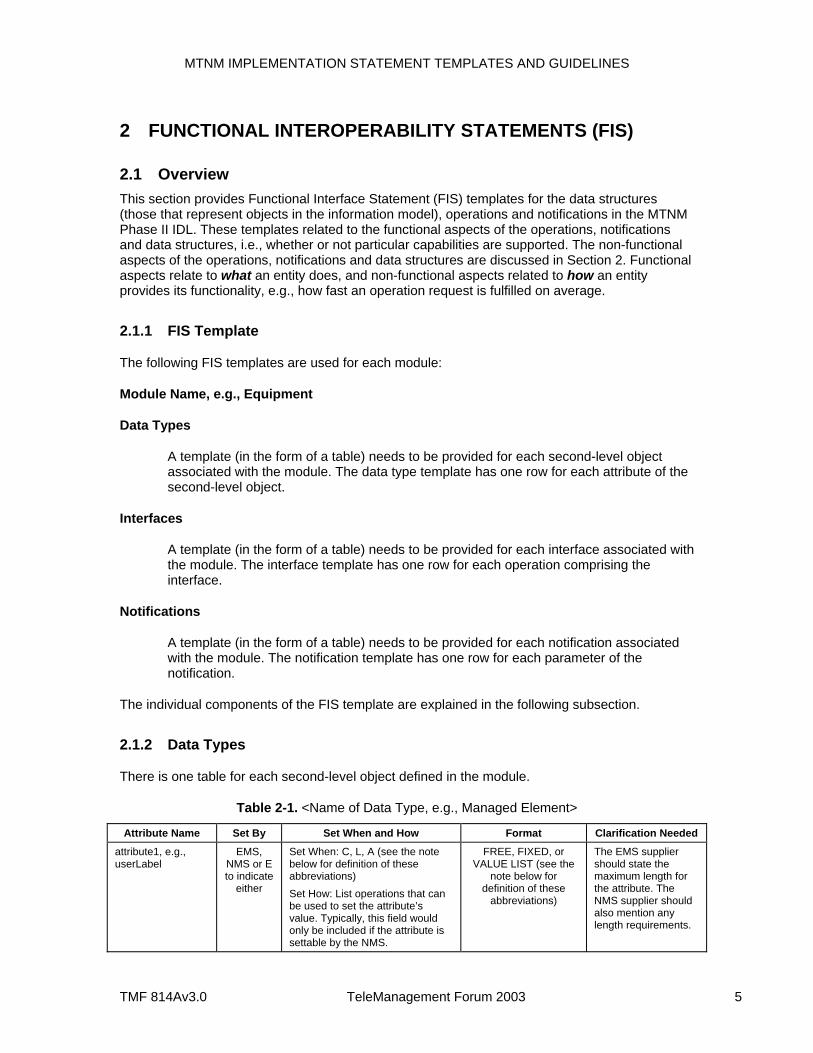
2.1.2 Data Types
There is one table for each second-level object defined in the module.
Table 2-1. <Name of Data Type, e.g., Managed Element>
Attribute Name Set By Set When and How Format Clarification Needed
attribute1, e.g., userLabel
EMS, NMS or E to indicate
either
Set When: C, L, A (see the note below for definition of these abbreviations) Set How: List operations that can be used to set the attribute’s value. Typically, this field would only be included if the attribute is settable by the NMS.
FREE, FIXED, or VALUE LIST (see the
note below for definition of these
abbreviations)
The EMS supplier should state the maximum length for the attribute. The NMS supplier should also mention any length requirements.
MTNM IMPLEMENTATION STATEMENT TEMPLATES AND GUIDELINES
TMF 814Av3.0 TeleManagement Forum 2003 6
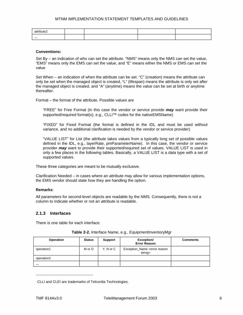
attribute2
…
Conventions:
Set By – an indication of who can set the attribute. “NMS” means only the NMS can set the value, “EMS” means only the EMS can set the value, and “E” means either the NMS or EMS can set the value
Set When – an indication of when the attribute can be set. “C” (creation) means the attribute can only be set when the managed object is created, “L” (lifespan) means the attribute is only set after the managed object is created, and “A” (anytime) means the value can be set at birth or anytime thereafter.
Format – the format of the attribute. Possible values are
“FREE” for Free Format (in this case the vendor or service provide may want provide their supported/required format(s), e.g., CLLI™ codes for the nativeEMSName)
“FIXED” for Fixed Format (the format is defined in the IDL and must be used without variance, and no additional clarification is needed by the vendor or service provider)
“VALUE LIST” for List (the attribute takes values from a typically long set of possible values defined in the IDL, e.g., layerRate, pmParameterName). In this case, the vendor or service provider may want to provide their supported/required set of values. VALUE LIST is used in only a few places in the following tables. Basically, a VALUE LIST is a data type with a set of supported values.
These three categories are meant to be mutually exclusive.
Clarification Needed – in cases where an attribute may allow for various implementation options, the EMS vendor should state how they are handling the option.
Remarks:
All parameters for second-level objects are readable by the NMS. Consequently, there is not a column to indicate whether or not an attribute is readable.
2.1.3 Interfaces
There is one table for each interface.
Table 2-2. Interface Name, e.g., EquipmentInventoryMgr
Operation Status Support Exception/ Error Reason
Comments
operation1 M or O Y, N or C Exception_Name <error reason string>
operation2
…
CLLI and CLEI are trademarks of Telcordia Technologies.
MTNM IMPLEMENTATION STATEMENT TEMPLATES AND GUIDELINES
TMF 814Av3.0 TeleManagement Forum 2003 7
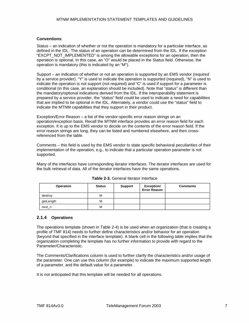
Conventions:
Status – an indication of whether or not the operation is mandatory for a particular interface, as defined in the IDL. The status of an operation can be determined from the IDL. If the exception “EXCPT_NOT_IMPLEMENTED” is among the allowable exceptions for an operation, then the operation is optional. In this case, an “O” would be placed in the Status field. Otherwise, the operation is mandatory (this is indicated by an “M”).
Support – an indication of whether or not an operation is supported by an EMS vendor (required by a service provider). “Y” is used to indicate the operation is supported (required), “N” is used to indicate the operation is not support (not required) and “C” is used if support for a parameter is conditional (in this case, an explanation should be included). Note that “status” is different than the mandatory/optional indications derived from the IDL. If the interoperability statement is prepared by a service provider, the “status” field could be used to indicate a need for capabilities that are implied to be optional in the IDL. Alternately, a vendor could use the “status” field to indicate the MTNM capabilities that they support in their product.
Exception/Error Reason – a list of the vendor-specific error reason strings on an operation/exception basis. Recall the MTNM interface provides an error reason field for each exception. It is up to the EMS vendor to decide on the contents of the error reason field. If the error reason strings are long, they can be listed and numbered elsewhere, and then cross-referenced from the table.
Comments – this field is used by the EMS vendor to state specific behavioral peculiarities of their implementation of the operation, e.g., to indicate that a particular operation parameter is not supported.
Many of the interfaces have corresponding iterator interfaces. The iterator interfaces are used for the bulk retrieval of data. All of the iterator interfaces have the same operations.
Table 2-3. General Iterator Interface
Operation Status Support Exception/ Error Reason
Comments
destroy M
getLength M
next_n M
2.1.4 Operations
The operations template (shown in Table 2-4) is be used when an organization (that is creating a profile of TMF 814) needs to further define characteristics and/or behavior for an operation (beyond that specified in the interface template). A blank cell in the following table implies that the organization completing the template has no further information to provide with regard to the Parameter/Characteristic.
The Comments/Clarifications column is used to further clarify the characteristics and/or usage of the parameter. One can use this column (for example) to indicate the maximum supported length of a parameter, and the default value for a parameter.
It is not anticipated that this template will be needed for all operations.
MTNM IMPLEMENTATION STATEMENT TEMPLATES AND GUIDELINES
TMF 814Av3.0 TeleManagement Forum 2003 8
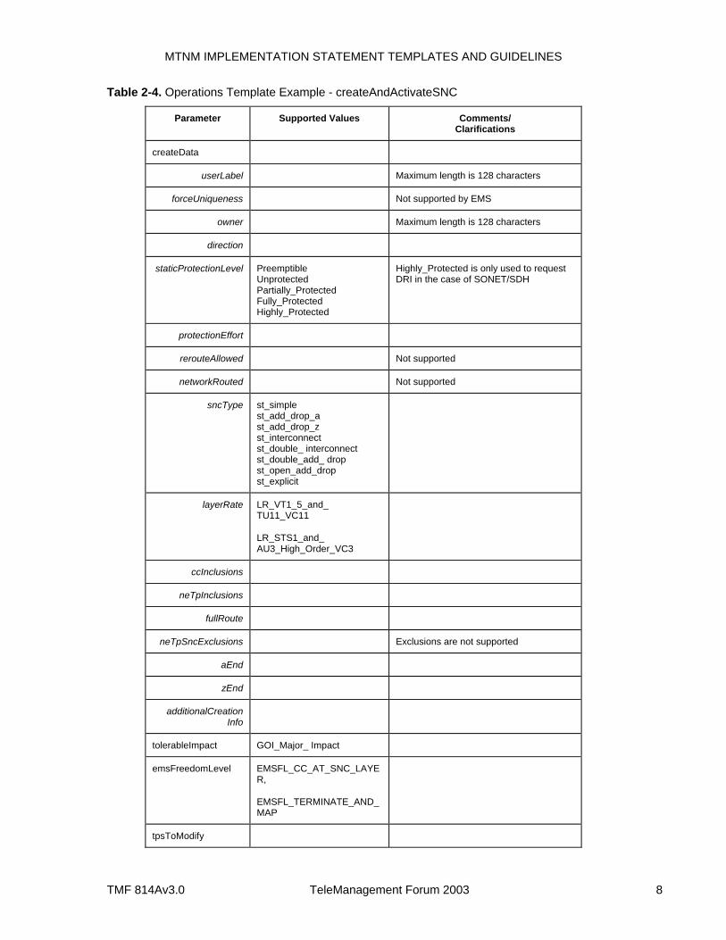
Table 2-4. Operations Template Example - createAndActivateSNC
Parameter Supported Values Comments/ Clarifications
createData
userLabel Maximum length is 128 characters
forceUniqueness Not supported by EMS
owner Maximum length is 128 characters
direction
staticProtectionLevel Preemptible Unprotected Partially_Protected Fully_Protected Highly_Protected
Highly_Protected is only used to request DRI in the case of SONET/SDH
protectionEffort
rerouteAllowed Not supported
networkRouted Not supported
sncType st_simple st_add_drop_a st_add_drop_z st_interconnect st_double_ interconnect st_double_add_ drop st_open_add_drop st_explicit
layerRate LR_VT1_5_and_ TU11_VC11
LR_STS1_and_ AU3_High_Order_VC3
ccInclusions
neTpInclusions
fullRoute
neTpSncExclusions Exclusions are not supported
aEnd
zEnd
additionalCreation Info
tolerableImpact GOI_Major_ Impact
emsFreedomLevel EMSFL_CC_AT_SNC_LAYER,
EMSFL_TERMINATE_AND_MAP
tpsToModify
MTNM IMPLEMENTATION STATEMENT TEMPLATES AND GUIDELINES
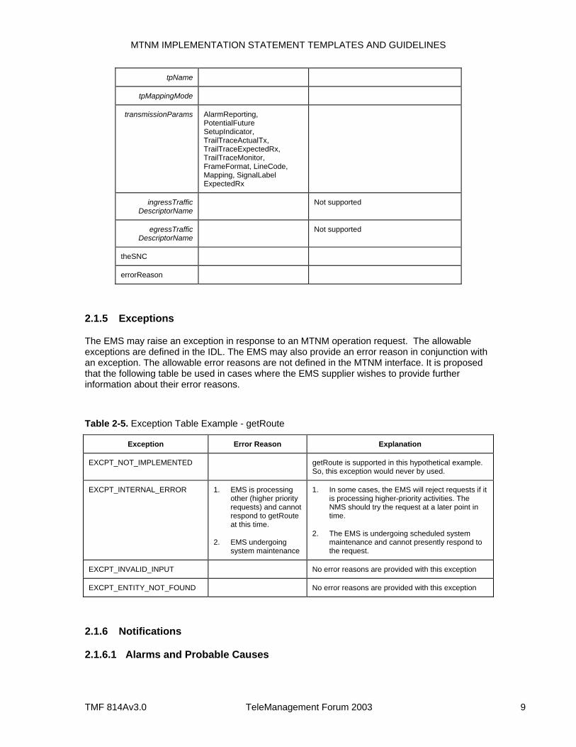
TMF 814Av3.0 TeleManagement Forum 2003 9
tpName
tpMappingMode
transmissionParams AlarmReporting, PotentialFuture SetupIndicator, TrailTraceActualTx, TrailTraceExpectedRx, TrailTraceMonitor, FrameFormat, LineCode, Mapping, SignalLabel ExpectedRx
ingressTraffic DescriptorName
Not supported
egressTraffic DescriptorName
Not supported
theSNC
errorReason
2.1.5 Exceptions
The EMS may raise an exception in response to an MTNM operation request. The allowable exceptions are defined in the IDL. The EMS may also provide an error reason in conjunction with an exception. The allowable error reasons are not defined in the MTNM interface. It is proposed that the following table be used in cases where the EMS supplier wishes to provide further information about their error reasons.
Table 2-5. Exception Table Example - getRoute
Exception Error Reason Explanation
EXCPT_NOT_IMPLEMENTED getRoute is supported in this hypothetical example. So, this exception would never by used.
EXCPT_INTERNAL_ERROR 1. EMS is processing other (higher priority requests) and cannot respond to getRoute at this time.
2. EMS undergoing system maintenance
1. In some cases, the EMS will reject requests if it is processing higher-priority activities. The NMS should try the request at a later point in time.
2. The EMS is undergoing scheduled system maintenance and cannot presently respond to the request.
EXCPT_INVALID_INPUT No error reasons are provided with this exception
EXCPT_ENTITY_NOT_FOUND No error reasons are provided with this exception
2.1.6 Notifications
2.1.6.1 Alarms and Probable Causes
MTNM IMPLEMENTATION STATEMENT TEMPLATES AND GUIDELINES
TMF 814Av3.0 TeleManagement Forum 2003 10
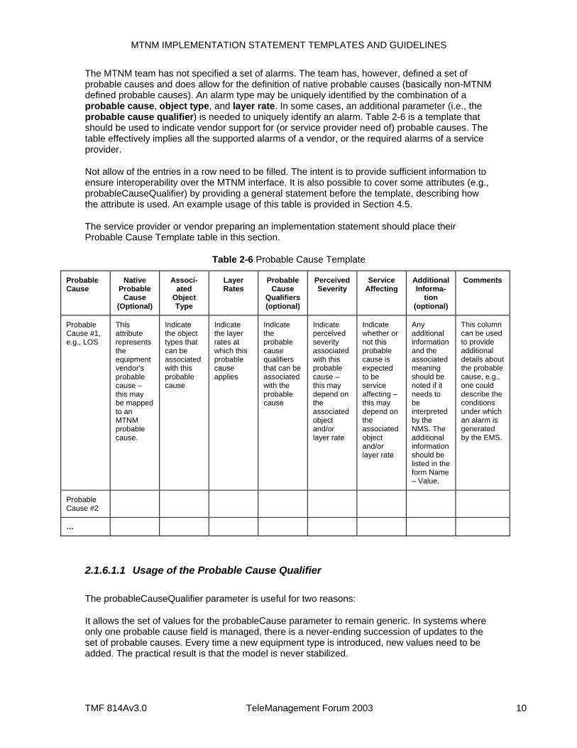
The MTNM team has not specified a set of alarms. The team has, however, defined a set of probable causes and does allow for the definition of native probable causes (basically non-MTNM defined probable causes). An alarm type may be uniquely identified by the combination of a probable cause, object type, and layer rate. In some cases, an additional parameter (i.e., the probable cause qualifier) is needed to uniquely identify an alarm. Table 2-6 is a template that should be used to indicate vendor support for (or service provider need of) probable causes. The table effectively implies all the supported alarms of a vendor, or the required alarms of a service provider.
Not allow of the entries in a row need to be filled. The intent is to provide sufficient information to ensure interoperability over the MTNM interface. It is also possible to cover some attributes (e.g., probableCauseQualifier) by providing a general statement before the template, describing how the attribute is used. An example usage of this table is provided in Section 4.5.
The service provider or vendor preparing an implementation statement should place their Probable Cause Template table in this section.
Table 2-6 Probable Cause Template
Probable Cause
Native Probable
Cause (Optional)
Associ-ated
Object Type
Layer Rates
Probable Cause
Qualifiers (optional)
Perceived Severity
Service Affecting
Additional Informa-
tion (optional)
Comments
Probable Cause #1, e.g., LOS
This attribute represents the equipment vendor’s probable cause – this may be mapped to an MTNM probable cause.
Indicate the object types that can be associated with this probable cause
Indicate the layer rates at which this probable cause applies
Indicate the probable cause qualifiers that can be associated with the probable cause
Indicate perceived severity associated with this probable cause – this may depend on the associated object and/or layer rate
Indicate whether or not this probable cause is expected to be service affecting – this may depend on the associated object and/or layer rate
Any additional information and the associated meaning should be noted if it needs to be interpreted by the NMS. The additional information should be listed in the form Name – Value.
This column can be used to provide additional details about the probable cause, e.g., one could describe the conditions under which an alarm is generated by the EMS.
Probable Cause #2
…
2.1.6.1.1 Usage of the Probable Cause Qualifier
The probableCauseQualifier parameter is useful for two reasons:
It allows the set of values for the probableCause parameter to remain generic. In systems where only one probable cause field is managed, there is a never-ending succession of updates to the set of probable causes. Every time a new equipment type is introduced, new values need to be added. The practical result is that the model is never stabilized.
MTNM IMPLEMENTATION STATEMENT TEMPLATES AND GUIDELINES
TMF 814Av3.0 TeleManagement Forum 2003 11
It allows several alarms to be sent from the same object, with the same probable cause, while still remaining identifiably different. (The alternative would be to manage unique values of the notification identifier, but some EMS vendors have problems with that.)
Note that probableCause qualifier is not necessarily human readable, as its real purpose is to satisfy the second point. For instance, if the EMS works internally with a GDMO model, then it might use a GDMO probableCause and specificProblems attribute values (which are sequences of integers, not very exciting to read). The additionalText parameter is there to tell the human operator what is going on.
Example 1:
Consider a vendor that has a line terminal NE that issues the following native alarms from the same termination point and layer rate:
DegradedSignal
fecUncorrectedBlocks (meaning that our Reed-Solomon Forward Error Correcting algorithm has rejected some frames)
Both these alarms are mapped to the generic probable cause BER_SD (i.e., "signal degraded"). The probableCauseQualifier, nativeEMSProbableCause and possibly the additionalText parameters distinguish between the two. Note that this saves one the trouble of going to TM Forum MTNM standards group and asking for a new probableCause value, and even better, it saves the NMS vendor the trouble of managing a new fault condition which from their point of view is equivalent to the other one ("a difference that makes no difference is no difference").
Example 2:
Just consider all the equipment alarms that can be generated by all the equipment vendors. The MTNM interface designers intentionally use a single probableCause value “EQPT” for all of them. The implication is that it is not expected for the NMS to discriminate between hundreds of equipment conditions.
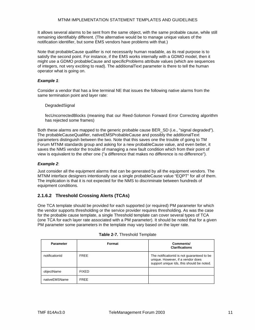
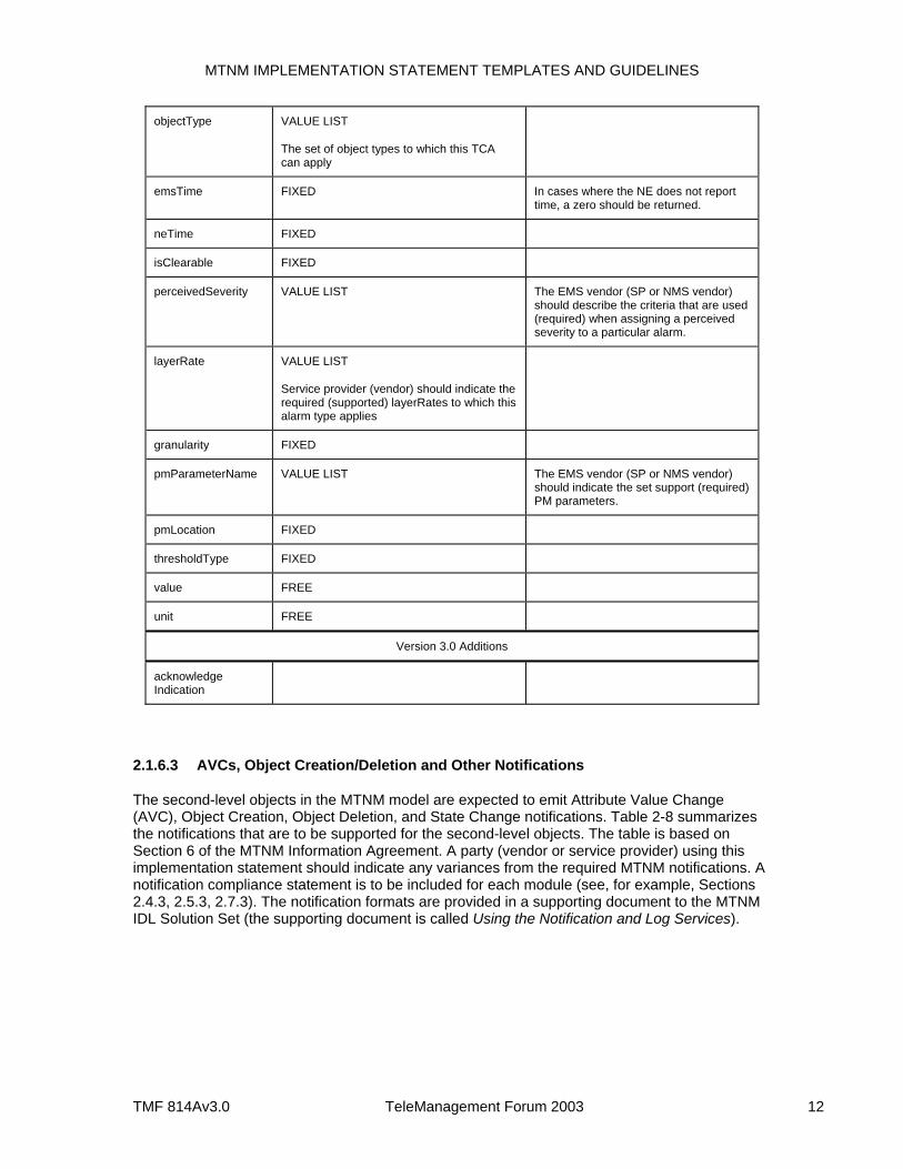
2.1.6.2 Threshold Crossing Alerts (TCAs)
One TCA template should be provided for each supported (or required) PM parameter for which the vendor supports thresholding or the service provider requires thresholding. As was the case for the probable cause template, a single Threshold template can cover several types of TCA (one TCA for each layer rate associated with a PM parameter). It should be noted that for a given PM parameter some parameters in the template may vary based on the layer rate.
Table 2-7. Threshold Template
Parameter Format Comments/ Clarifications
notificationId FREE The notificationId is not guaranteed to be unique. However, if a vendor does support unique Ids, this should be noted.
objectName FIXED
nativeEMSName FREE
MTNM IMPLEMENTATION STATEMENT TEMPLATES AND GUIDELINES
TMF 814Av3.0 TeleManagement Forum 2003 12
objectType VALUE LIST
The set of object types to which this TCA can apply
emsTime FIXED In cases where the NE does not report time, a zero should be returned.
neTime FIXED
isClearable FIXED
perceivedSeverity VALUE LIST The EMS vendor (SP or NMS vendor) should describe the criteria that are used (required) when assigning a perceived severity to a particular alarm.
layerRate VALUE LIST
Service provider (vendor) should indicate the required (supported) layerRates to which this alarm type applies
granularity FIXED
pmParameterName VALUE LIST The EMS vendor (SP or NMS vendor) should indicate the set support (required) PM parameters.
pmLocation FIXED
thresholdType FIXED
value FREE
unit FREE
Version 3.0 Additions
acknowledge Indication
2.1.6.3 AVCs, Object Creation/Deletion and Other Notifications
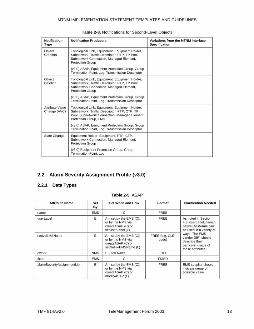
The second-level objects in the MTNM model are expected to emit Attribute Value Change (AVC), Object Creation, Object Deletion, and State Change notifications. Table 2-8 summarizes the notifications that are to be supported for the second-level objects. The table is based on Section 6 of the MTNM Information Agreement. A party (vendor or service provider) using this implementation statement should indicate any variances from the required MTNM notifications. A notification compliance statement is to be included for each module (see, for example, Sections 2.4.3, 2.5.3, 2.7.3). The notification formats are provided in a supporting document to the MTNM IDL Solution Set (the supporting document is called Using the Notification and Log Services).
MTNM IMPLEMENTATION STATEMENT TEMPLATES AND GUIDELINES
TMF 814Av3.0 TeleManagement Forum 2003 13
Table 2-8. Notifications for Second-Level Objects
Notification Type
Notification Producers Variations from the MTNM Interface Specification
Object Creation
Topological Link, Equipment, Equipment Holder, Subnetwork, Traffic Descriptor, PTP, TP Pool, Subnetwork Connection, Managed Element, Protection Group
(v3.0) ASAP, Equipment Protection Group, Group Termination Point, Log, Transmission Descriptor
Object Deletion
Topological Link, Equipment, Equipment Holder, Subnetwork, Traffic Descriptor, PTP, TP Pool, Subnetwork Connection, Managed Element, Protection Group
(v3.0) ASAP, Equipment Protection Group, Group Termination Point, Log, Transmission Descriptor
Attribute Value Change (AVC)
Topological Link, Equipment, Equipment Holder, Subnetwork, Traffic Descriptor, PTP, CTP, TP Pool, Subnetwork Connection, Managed Element, Protection Group, EMS
(v3.0) ASAP, Equipment Protection Group, Group Termination Point, Log, Transmission Descriptor
State Change Equipment Holder, Equipment, PTP, CTP, Subnetwork Connection, Managed Element, Protection Group
(v3.0) Equipment Protection Group, Group Termination Point, Log
2.2 Alarm Severity Assignment Profile (v3.0)
2.2.1 Data Types
Table 2-9. ASAP
Attribute Name Set By
Set When and How Format Clarification Needed
name EMS C FREE
userLabel E A – set by the EMS (C), or by the NMS via createASAP (C) or setUserLabel (L)
FREE
nativeEMSName E A – set by the EMS (C), or by the NMS via createASAP (C) or setNativeEMSName (L)
FREE (e.g. CLEI code)
owner NMS L – setOwner FREE
As noted in Section 4.3, userLabel, owner, nativeEMSName can be used in a variety of ways. The EMS vendor (SP) should describe their particular usage of these attributes.
fixed EMS C FIXED
alarmSeverityAssignmentList E A – set by the EMS (C), or by the NMS via createASAP (C) or modifyASAP (L)
FREE EMS supplier should indicate range of possible value
MTNM IMPLEMENTATION STATEMENT TEMPLATES AND GUIDELINES
TMF 814Av3.0 TeleManagement Forum 2003 14
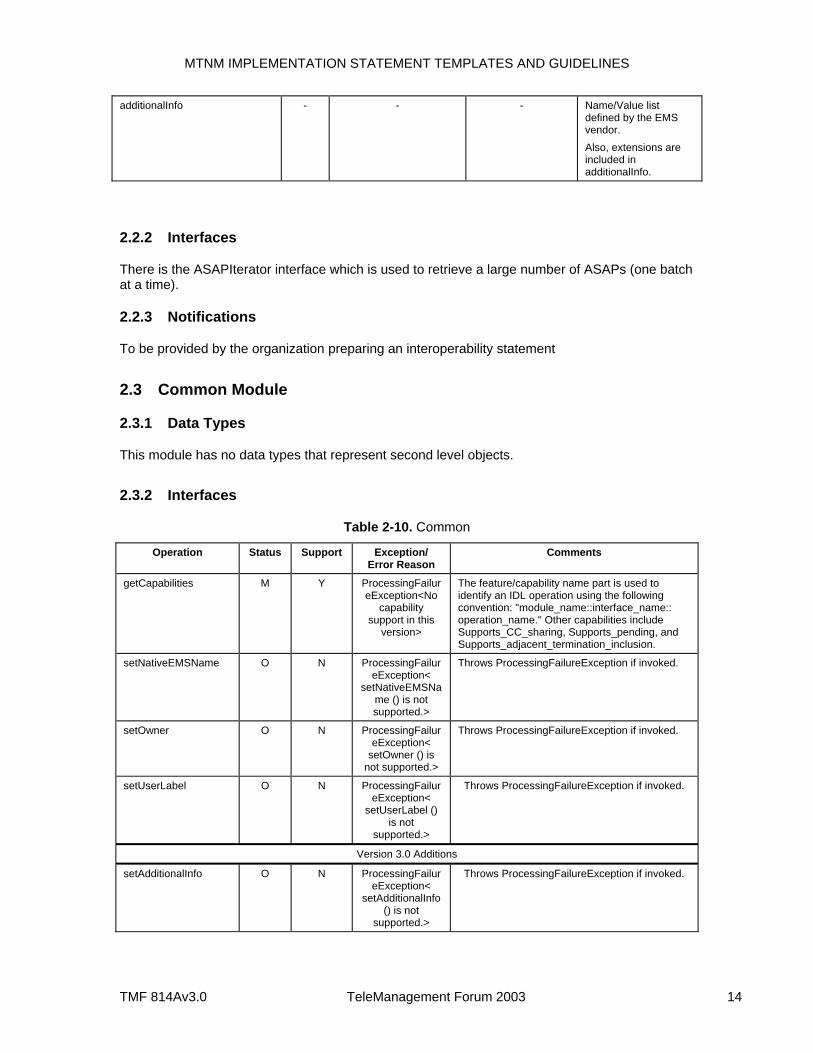
additionalInfo - - - Name/Value list defined by the EMS vendor. Also, extensions are included in additionalInfo.
2.2.2 Interfaces
There is the ASAPIterator interface which is used to retrieve a large number of ASAPs (one batch at a time).
2.2.3 Notifications
To be provided by the organization preparing an interoperability statement
2.3 Common Module
2.3.1 Data Types
This module has no data types that represent second level objects.
2.3.2 Interfaces
Table 2-10. Common
Operation Status Support Exception/ Error Reason
Comments
getCapabilities M Y ProcessingFailureException<No
capability support in this
version>
The feature/capability name part is used to identify an IDL operation using the following convention: "module_name::interface_name:: operation_name." Other capabilities include Supports_CC_sharing, Supports_pending, and Supports_adjacent_termination_inclusion.
setNativeEMSName O N ProcessingFailureException<
setNativeEMSName () is not supported.>
Throws ProcessingFailureException if invoked.
setOwner O N ProcessingFailureException<
setOwner () is not supported.>
Throws ProcessingFailureException if invoked.
setUserLabel O N ProcessingFailureException<
setUserLabel () is not
supported.>
Throws ProcessingFailureException if invoked.
Version 3.0 Additions
setAdditionalInfo O N ProcessingFailureException<
setAdditionalInfo () is not
supported.>
Throws ProcessingFailureException if invoked.
MTNM IMPLEMENTATION STATEMENT TEMPLATES AND GUIDELINES
TMF 814Av3.0 TeleManagement Forum 2003 15
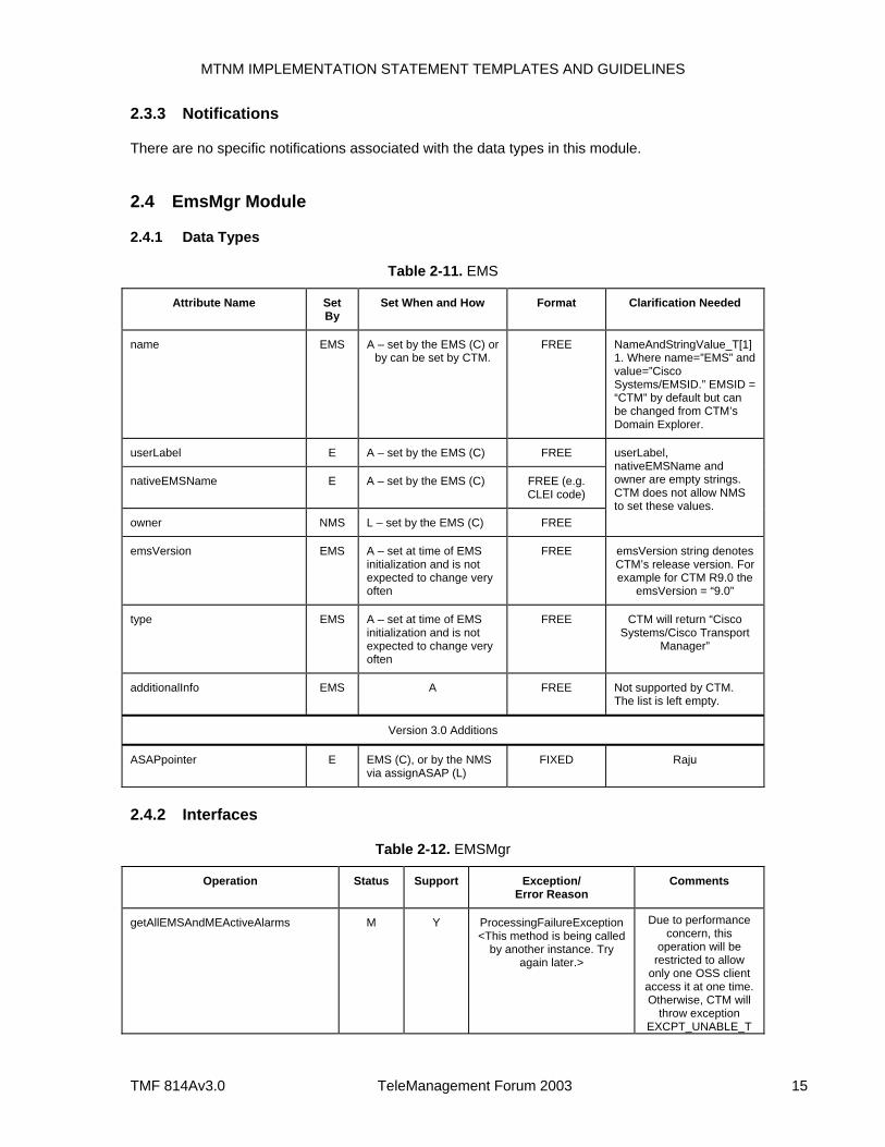
2.3.3 Notifications
There are no specific notifications associated with the data types in this module.
2.4 EmsMgr Module
2.4.1 Data Types
Table 2-11. EMS
Attribute Name Set By
Set When and How Format Clarification Needed
name EMS A – set by the EMS (C) or by can be set by CTM.
FREE NameAndStringValue_T[1] 1. Where name=”EMS” and value=”Cisco Systems/EMSID.” EMSID = “CTM” by default but can be changed from CTM’s Domain Explorer.
userLabel E A – set by the EMS (C) FREE
nativeEMSName E A – set by the EMS (C) FREE (e.g. CLEI code)
owner NMS L – set by the EMS (C) FREE
userLabel, nativeEMSName and owner are empty strings. CTM does not allow NMS to set these values.
emsVersion EMS A – set at time of EMS initialization and is not expected to change very often
FREE emsVersion string denotes CTM’s release version. For example for CTM R9.0 the
emsVersion = “9.0”
type EMS A – set at time of EMS initialization and is not expected to change very often
FREE CTM will return “Cisco Systems/Cisco Transport
Manager”
additionalInfo EMS A FREE Not supported by CTM. The list is left empty.
Version 3.0 Additions
ASAPpointer E EMS (C), or by the NMS via assignASAP (L)
FIXED Raju
2.4.2 Interfaces
Table 2-12. EMSMgr
Operation Status Support Exception/ Error Reason
Comments
getAllEMSAndMEActiveAlarms M Y ProcessingFailureException<This method is being called
by another instance. Try again later.>
Due to performance concern, this
operation will be restricted to allow
only one OSS client access it at one time. Otherwise, CTM will
throw exception EXCPT_UNABLE_T
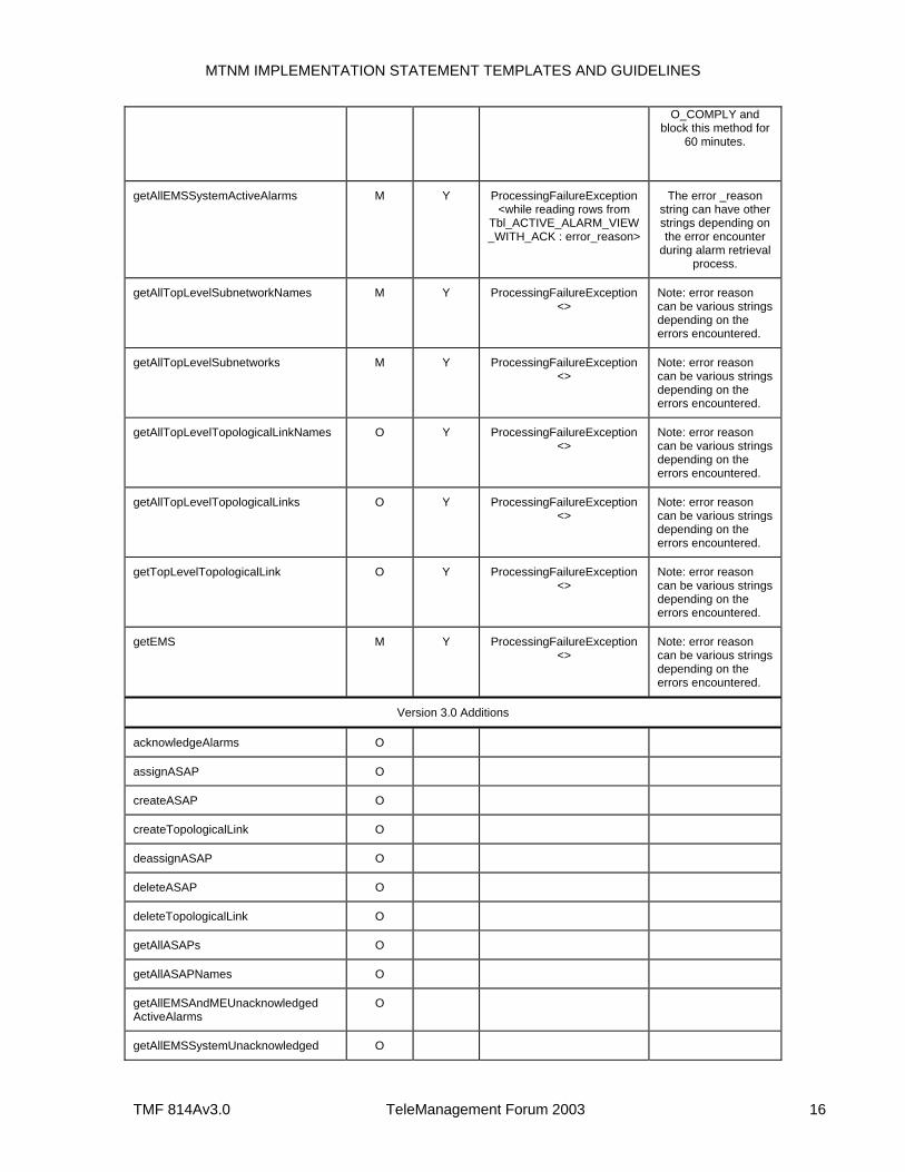
MTNM IMPLEMENTATION STATEMENT TEMPLATES AND GUIDELINES
TMF 814Av3.0 TeleManagement Forum 2003 16
O_COMPLY and block this method for
60 minutes.
getAllEMSSystemActiveAlarms M Y ProcessingFailureException<while reading rows from
Tbl_ACTIVE_ALARM_VIEW_WITH_ACK : error_reason>
The error _reason string can have other strings depending on the error encounter
during alarm retrieval process.
getAllTopLevelSubnetworkNames M Y ProcessingFailureException<>
Note: error reason can be various strings depending on the errors encountered.
getAllTopLevelSubnetworks M Y ProcessingFailureException<>
Note: error reason can be various strings depending on the errors encountered.
getAllTopLevelTopologicalLinkNames O Y ProcessingFailureException<>
Note: error reason can be various strings depending on the errors encountered.
getAllTopLevelTopologicalLinks O Y ProcessingFailureException<>
Note: error reason can be various strings depending on the errors encountered.
getTopLevelTopologicalLink O Y ProcessingFailureException<>
Note: error reason can be various strings depending on the errors encountered.
getEMS M Y ProcessingFailureException<>
Note: error reason can be various strings depending on the errors encountered.
Version 3.0 Additions
acknowledgeAlarms O
assignASAP O
createASAP O
createTopologicalLink O
deassignASAP O
deleteASAP O
deleteTopologicalLink O
getAllASAPs O
getAllASAPNames O
getAllEMSAndMEUnacknowledged ActiveAlarms
O
getAllEMSSystemUnacknowledged O
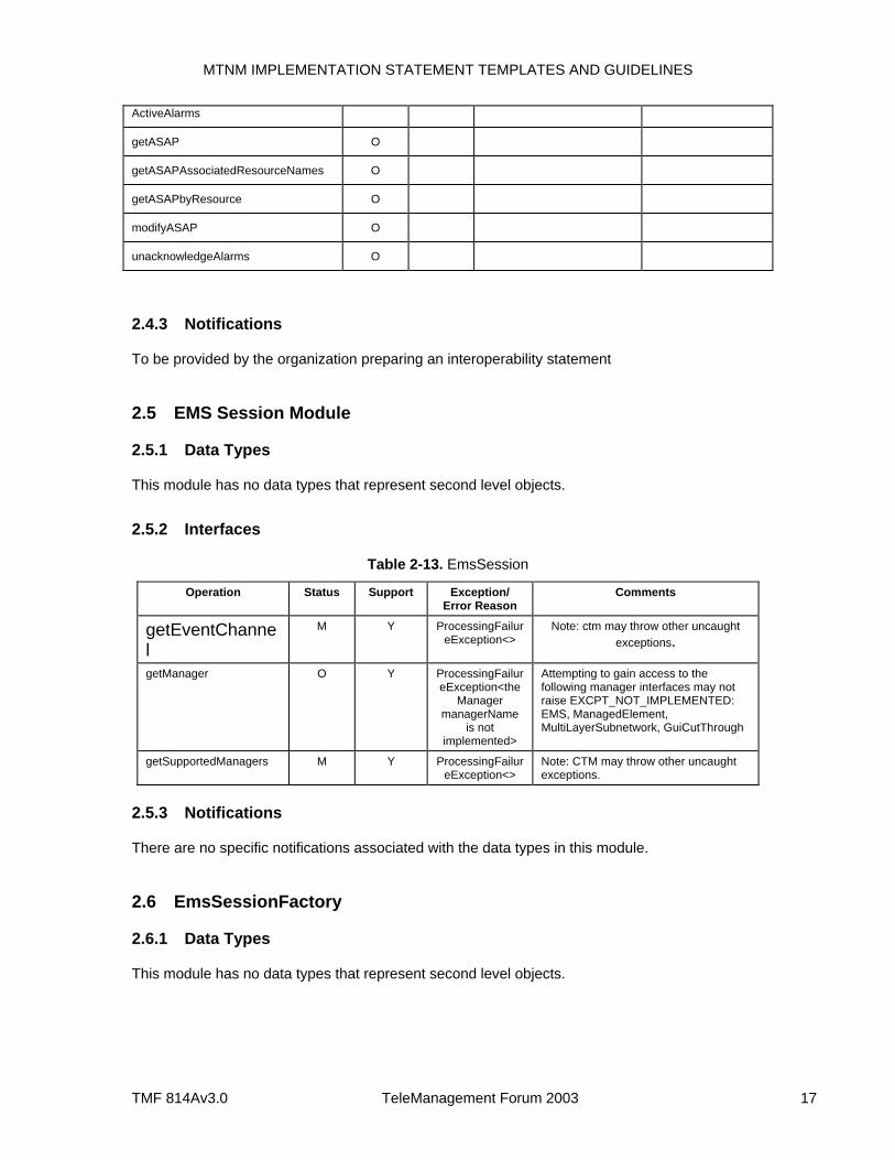
MTNM IMPLEMENTATION STATEMENT TEMPLATES AND GUIDELINES
TMF 814Av3.0 TeleManagement Forum 2003 17
ActiveAlarms
getASAP O
getASAPAssociatedResourceNames O
getASAPbyResource O
modifyASAP O
unacknowledgeAlarms O
2.4.3 Notifications
To be provided by the organization preparing an interoperability statement
2.5 EMS Session Module
2.5.1 Data Types
This module has no data types that represent second level objects.
2.5.2 Interfaces
Table 2-13. EmsSession
Operation Status Support Exception/ Error Reason
Comments
getEventChannel
M Y ProcessingFailureException<>
Note: ctm may throw other uncaught exceptions.
getManager O Y ProcessingFailureException<the
Manager managerName
is not implemented>
Attempting to gain access to the following manager interfaces may not raise EXCPT_NOT_IMPLEMENTED: EMS, ManagedElement, MultiLayerSubnetwork, GuiCutThrough
getSupportedManagers M Y ProcessingFailureException<>
Note: CTM may throw other uncaught exceptions.
2.5.3 Notifications
There are no specific notifications associated with the data types in this module.
2.6 EmsSessionFactory
2.6.1 Data Types
This module has no data types that represent second level objects.
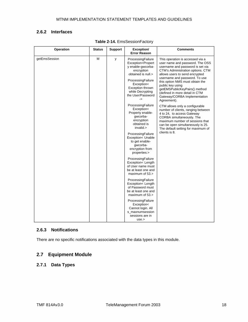
MTNM IMPLEMENTATION STATEMENT TEMPLATES AND GUIDELINES
TMF 814Av3.0 TeleManagement Forum 2003 18
2.6.2 Interfaces
Table 2-14. EmsSessionFactory
Operation Status Support Exception/ Error Reason
Comments
getEmsSession M y ProcessingFailureException<Property enable-gwcorba-
encryption obtained is null.>
ProcessingFailureException<
Exception thrown while Decrypting
the User/Password ->
ProcessingFailureException<
Property enable-gwcorba-encryption obtained is
invalid.>
ProcessingFailureException< Unable
to get enable-gwcorba-
encryption from properties:>
ProcessingFailureException< Length of User name must be at least one and maximum of 53.>
ProcessingFailureException< Length of Password must
be at least one and maximum of 53.>
ProcessingFailureException<
Cannot login. All s_maxnumsession
sessions are in use.>
This operation is accessed via a user name and password. The OSS username and password is set via CTM’s Administration options. CTM allows users to send encrypted username and password. To use this option NMS must obtain the public key using getEMSPublicKeyPairs() method (defined in more detail in CTM Gateway/CORBA Implementation Agreement).
CTM allows only a configurable number of clients, ranging between 4 to 24, to access Gateway CORBA simultaneously. The maximum number of sessions that can be open simultaneously is 25. The default setting for maximum of clients is 8.
2.6.3 Notifications
There are no specific notifications associated with the data types in this module.
2.7 Equipment Module
2.7.1 Data Types
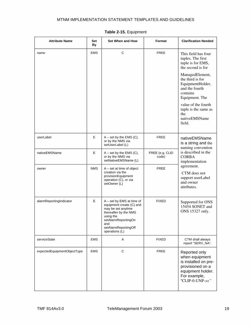
MTNM IMPLEMENTATION STATEMENT TEMPLATES AND GUIDELINES
TMF 814Av3.0 TeleManagement Forum 2003 19
Table 2-15. Equipment
Attribute Name Set By
Set When and How Format Clarification Needed
name EMS C FREE This field has four tuples. The first tuple is for EMS, the second is for
ManagedElement, the third is for EquipmentHolder, and the fourth contains Equipment. The
value of the fourth tuple is the same as the nativeEMSName field.
userLabel E A – set by the EMS (C), or by the NMS via setUserLabel (L)
FREE
nativeEMSName E A – set by the EMS (C), or by the NMS via setNativeEMSName (L)
FREE (e.g. CLEI code)
owner NMS A – set at time of object creation via the provisionEquipment operation (C), or via setOwner (L)
FREE
nativeEMSName is a string and the naming convention is described in the CORBA implementation agreement.
CTM does not support userLabel and owner attributes.
alarmReportingIndicator E A – set by EMS at time of equipment create (C) and may be set anytime thereafter by the NMS using the setAlarmReportingOn and setAlarmReportingOff operations (L)
FIXED Supported for ONS 15454 SONET and ONS 15327 only.
serviceState EMS A FIXED CTM shall always report “SERV_NA”.
expectedEquipmentObjectType EMS C FREE Reported only when equipment is installed on pre-provisioned on a equipment holder. For example, “CLIP-0-UNP-xx’’
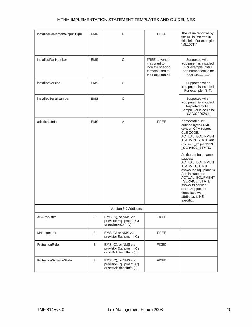
MTNM IMPLEMENTATION STATEMENT TEMPLATES AND GUIDELINES
TMF 814Av3.0 TeleManagement Forum 2003 20
installedEquipmentObjectType EMS L FREE The value reported by the NE is inserted in this field. For example, “ML100T.”
installedPartNumber EMS C Supported when equipment is installed.
For example install part number could be
“800-19622-01.”
installedVersion EMS C Supported when equipment is installed.
For example, “3.4”.
installedSerialNumber EMS C
FREE (a vendor may want to indicate specific formats used for their equipment)
Supported when equipment is installed.
Reported by NE. Sample value could be
“SAG07299Z6J.”
additionalInfo EMS A FREE Name/Value list defined by the EMS vendor. CTM reports CLEICODE, ACTUAL_EQUIPMENT_ADMIN_STATE and ACTUAL_EQUPMENT _SERVICE_STATE.
As the attribute names suggest ACTUAL_EQUIPMENT_ADMIN_STATE shows the equipment’s Admin state and ACTUAL_EQUPMENT _SERVICE_STATE shows its service state. Support for these last two attributes is NE specific..
Version 3.0 Additions
ASAPpointer E EMS (C), or NMS via provisionEquipment (C) or assignASAP (L)
FIXED
Manufacturer E EMS (C) or NMS via provisionEquipment (C)
FREE
ProtectionRole E EMS (C), or NMS via provisionEquipment (C) or setAdditionalInfo (L)
FIXED
ProtectionSchemeState E EMS (C), or NMS via provisionEquipment (C) or setAdditionalInfo (L)
FIXED
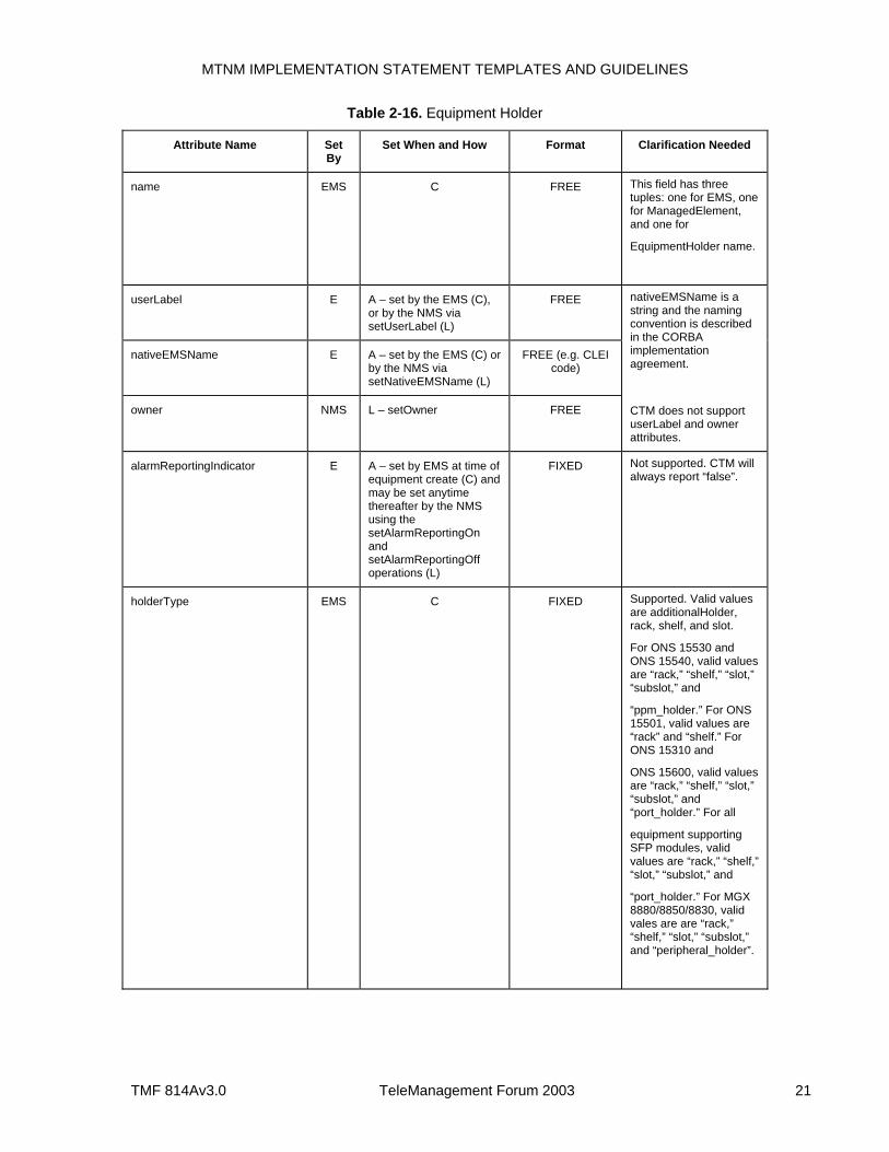
MTNM IMPLEMENTATION STATEMENT TEMPLATES AND GUIDELINES
TMF 814Av3.0 TeleManagement Forum 2003 21
Table 2-16. Equipment Holder
Attribute Name Set By
Set When and How Format Clarification Needed
name EMS C FREE This field has three tuples: one for EMS, one for ManagedElement, and one for
EquipmentHolder name.
userLabel E A – set by the EMS (C), or by the NMS via setUserLabel (L)
FREE
nativeEMSName E A – set by the EMS (C) or by the NMS via setNativeEMSName (L)
FREE (e.g. CLEI code)
owner NMS L – setOwner FREE
nativeEMSName is a string and the naming convention is described in the CORBA implementation agreement.
CTM does not support userLabel and owner attributes.
alarmReportingIndicator E A – set by EMS at time of equipment create (C) and may be set anytime thereafter by the NMS using the setAlarmReportingOn and setAlarmReportingOff operations (L)
FIXED Not supported. CTM will always report “false”.
holderType EMS C FIXED Supported. Valid values are additionalHolder, rack, shelf, and slot.
For ONS 15530 and ONS 15540, valid values are “rack,” “shelf,” “slot,” “subslot,” and
“ppm_holder.” For ONS 15501, valid values are “rack” and “shelf.” For ONS 15310 and
ONS 15600, valid values are “rack,” “shelf,” “slot,” “subslot,” and “port_holder.” For all
equipment supporting SFP modules, valid values are “rack,” “shelf,” “slot,” “subslot,” and
“port_holder.” For MGX 8880/8850/8830, valid vales are are “rack,” “shelf,” “slot,” “subslot,” and “peripheral_holder”.
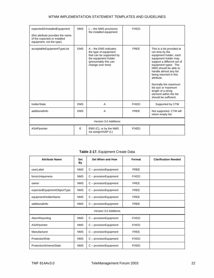
MTNM IMPLEMENTATION STATEMENT TEMPLATES AND GUIDELINES
TMF 814Av3.0 TeleManagement Forum 2003 22
expectedOrInstalledEquipment
(this attribute provides the name of the expected or installed equipment, not the type)
NMS L – the NMS provisions the installed equipment
FIXED
acceptableEquipmentTypeList EMS A – the EMS indicates the type of equipment that can be supported by the equipment holder (presumably this can change over time)
FREE This is a list provided at run time by the equipment holder, each equipment holder may support a different set of equipment types. The NMS should be able to handle almost any list being returned in this attribute.
Normally the maximum list size or maximum length of a string element within the list should be sufficient.
holderState EMS A FIXED Supported by CTM
additionalInfo EMS A FREE Not supported. CTM will return empty list.
Version 3.0 Additions
ASAPpointer E EMS (C), or by the NMS via assignASAP (L)
FIXED
Table 2-17. Equipment Create Data
Attribute Name Set By
Set When and How Format Clarification Needed
userLabel NMS C – provisionEquipment FREE
forceUniqueness NMS C – provisionEquipment FIXED
owner NMS C – provisionEquipment FREE
expectedEquipmentObjectType NMS C – provisionEquipment FREE
equipmentHolderName NMS C – provisionEquipment FREE
additionalInfo NMS C – provisionEquipment FREE
Version 3.0 Additions
AlarmReporting NMS C – provisionEquipment FIXED
ASAPpointer NMS C – provisionEquipment FIXED
Manufacturer NMS C – provisionEquipment FREE
ProtectionRole NMS C – provisionEquipment FIXED
ProtectionSchemeState NMS C – provisionEquipment FIXED
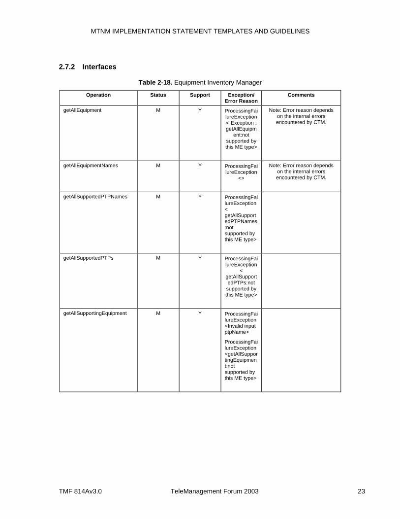
MTNM IMPLEMENTATION STATEMENT TEMPLATES AND GUIDELINES
TMF 814Av3.0 TeleManagement Forum 2003 23
2.7.2 Interfaces
Table 2-18. Equipment Inventory Manager
Operation Status Support Exception/ Error Reason
Comments
getAllEquipment M Y ProcessingFailureException< Exception : getAllEquipm
ent:not supported by this ME type>
Note: Error reason depends on the internal errors encountered by CTM.
getAllEquipmentNames M Y ProcessingFailureException
<>
Note: Error reason depends on the internal errors encountered by CTM.
getAllSupportedPTPNames M Y ProcessingFailureException< getAllSupportedPTPNames:not supported by this ME type>
getAllSupportedPTPs M Y ProcessingFailureException
< getAllSupportedPTPs:not
supported by this ME type>
getAllSupportingEquipment M Y ProcessingFailureException<Invalid input ptpName>
ProcessingFailureException <getAllSupportingEquipment:not supported by this ME type>
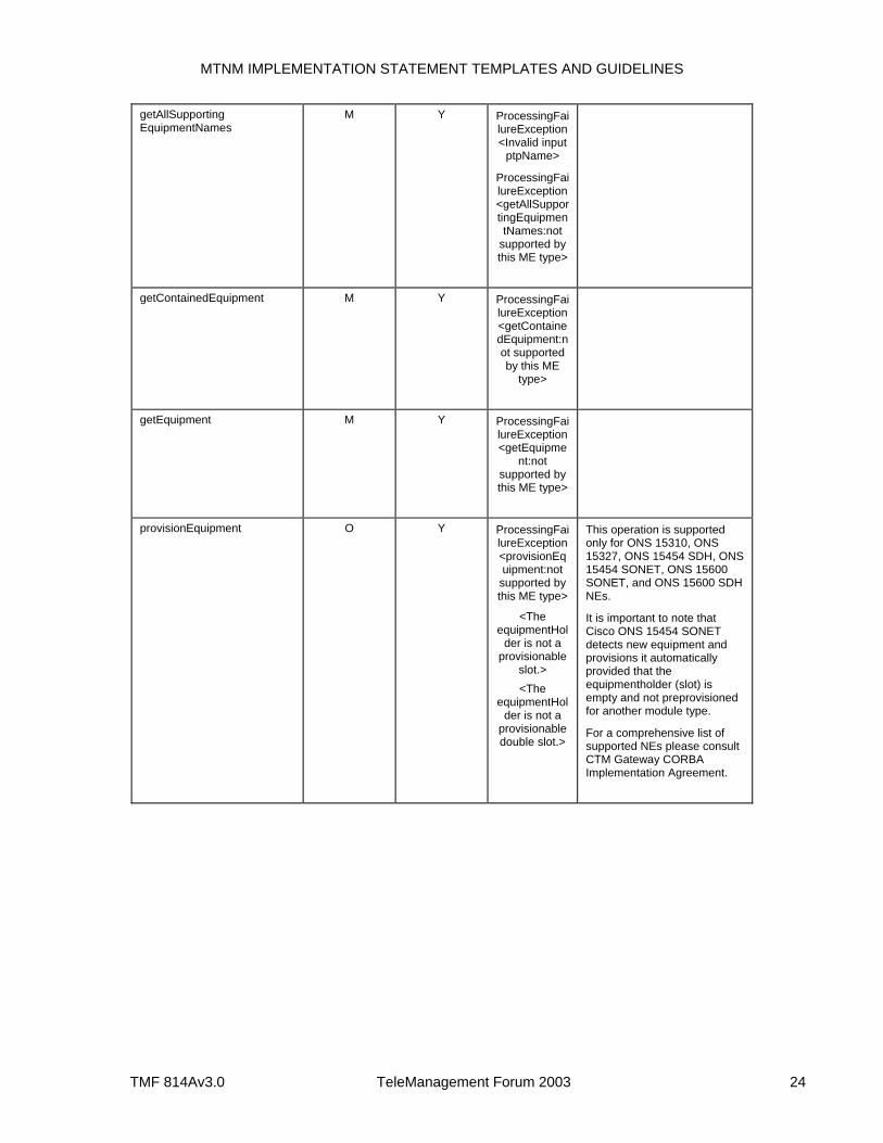
MTNM IMPLEMENTATION STATEMENT TEMPLATES AND GUIDELINES
TMF 814Av3.0 TeleManagement Forum 2003 24
getAllSupporting EquipmentNames
M Y ProcessingFailureException<Invalid input
ptpName>
ProcessingFailureException<getAllSupportingEquipmentNames:not
supported by this ME type>
getContainedEquipment M Y ProcessingFailureException<getContainedEquipment:not supported by this ME
type>
getEquipment M Y ProcessingFailureException<getEquipme
nt:not supported by this ME type>
provisionEquipment O Y ProcessingFailureException<provisionEquipment:not
supported by this ME type>
<The equipmentHol
der is not a provisionable
slot.> <The
equipmentHolder is not a
provisionable double slot.>
This operation is supported only for ONS 15310, ONS 15327, ONS 15454 SDH, ONS 15454 SONET, ONS 15600 SONET, and ONS 15600 SDH NEs.
It is important to note that Cisco ONS 15454 SONET detects new equipment and provisions it automatically provided that the equipmentholder (slot) is empty and not preprovisioned for another module type.
For a comprehensive list of supported NEs please consult CTM Gateway CORBA Implementation Agreement.
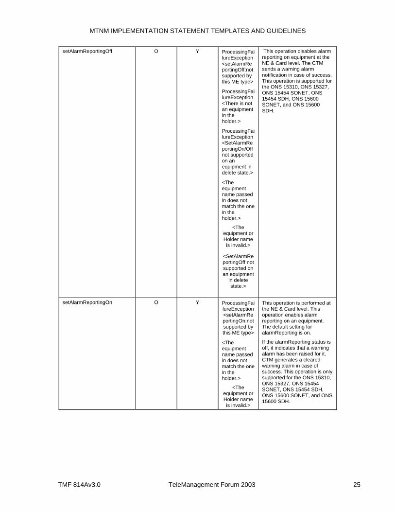
MTNM IMPLEMENTATION STATEMENT TEMPLATES AND GUIDELINES
TMF 814Av3.0 TeleManagement Forum 2003 25
setAlarmReportingOff O Y ProcessingFailureException<setAlarmReportingOff:not supported by this ME type>
ProcessingFailureException<There is not an equipment in the holder.>
ProcessingFailureException<SetAlarmReportingOn/Off not supported on an equipment in delete state.>
<The equipment name passed in does not match the one in the holder.>
<The equipment or Holder name is invalid.>
<SetAlarmReportingOff not supported on an equipment
in delete state.>
This operation disables alarm reporting on equipment at the NE & Card level. The CTM sends a warning alarm notification in case of success. This operation is supported for the ONS 15310, ONS 15327, ONS 15454 SONET, ONS 15454 SDH, ONS 15600 SONET, and ONS 15600 SDH.
setAlarmReportingOn O Y ProcessingFailureException<setAlarmReportingOn:not supported by this ME type>
<The equipment name passed in does not match the one in the holder.>
<The equipment or Holder name is invalid.>
This operation is performed at the NE & Card level. This operation enables alarm reporting on an equipment. The default setting for alarmReporting is on.
If the alarmReporting status is off, it indicates that a warning alarm has been raised for it. CTM generates a cleared warning alarm in case of success. This operation is only supported for the ONS 15310, ONS 15327, ONS 15454 SONET, ONS 15454 SDH, ONS 15600 SONET, and ONS 15600 SDH.
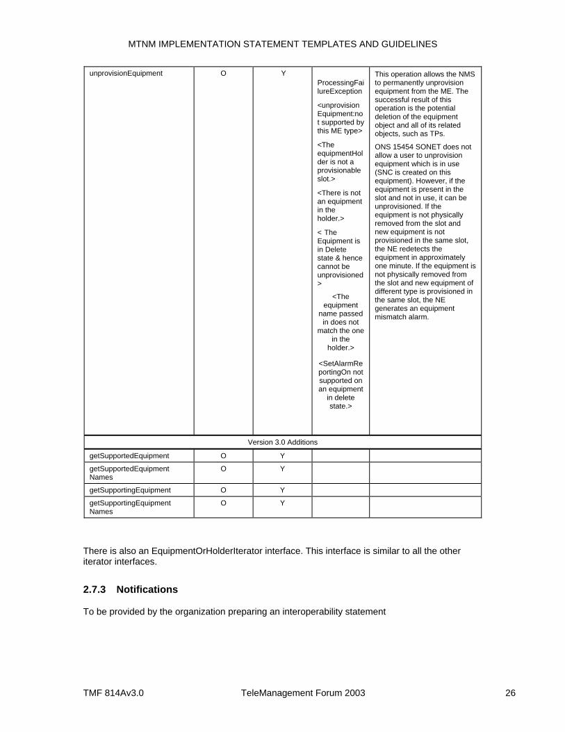
MTNM IMPLEMENTATION STATEMENT TEMPLATES AND GUIDELINES
TMF 814Av3.0 TeleManagement Forum 2003 26
unprovisionEquipment O Y ProcessingFailureException
<unprovisionEquipment:not supported by this ME type>
<The equipmentHolder is not a provisionable slot.>
<There is not an equipment in the holder.>
< The Equipment is in Delete state & hence cannot be unprovisioned>
<The equipment
name passed in does not
match the one in the
holder.>
<SetAlarmReportingOn not supported on an equipment
in delete state.>
This operation allows the NMS to permanently unprovision equipment from the ME. The successful result of this operation is the potential deletion of the equipment object and all of its related objects, such as TPs.
ONS 15454 SONET does not allow a user to unprovision equipment which is in use (SNC is created on this equipment). However, if the equipment is present in the slot and not in use, it can be unprovisioned. If the equipment is not physically removed from the slot and new equipment is not provisioned in the same slot, the NE redetects the equipment in approximately one minute. If the equipment is not physically removed from the slot and new equipment of different type is provisioned in the same slot, the NE generates an equipment mismatch alarm.
Version 3.0 Additions
getSupportedEquipment O Y
getSupportedEquipment Names
O Y
getSupportingEquipment O Y
getSupportingEquipment Names
O Y
There is also an EquipmentOrHolderIterator interface. This interface is similar to all the other iterator interfaces.
2.7.3 Notifications
To be provided by the organization preparing an interoperability statement
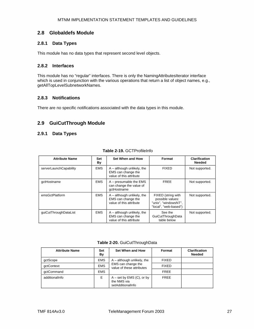
MTNM IMPLEMENTATION STATEMENT TEMPLATES AND GUIDELINES
TMF 814Av3.0 TeleManagement Forum 2003 27
2.8 Globaldefs Module
2.8.1 Data Types
This module has no data types that represent second level objects.
2.8.2 Interfaces
This module has no “regular” interfaces. There is only the NamingAttributesIterator interface which is used in conjunction with the various operations that return a list of object names, e.g., getAllTopLevelSubnetworkNames.
2.8.3 Notifications
There are no specific notifications associated with the data types in this module.
2.9 GuiCutThrough Module
2.9.1 Data Types
Table 2-19. GCTProfileInfo
Attribute Name Set By
Set When and How Format Clarification Needed
serverLaunchCapability EMS A – although unlikely, the EMS can change the value of this attribute
FIXED Not supported.
gctHostname EMS A – presumable the EMS can change the value of gctHostname
FREE Not supported.
emsGctPlatform EMS A – although unlikely, the EMS can change the value of this attribute
FIXED (string with possible values:
"unix", "windowsNT", "local", "web-based")
Not supported.
guiCutThroughDataList EMS A – although unlikely, the EMS can change the value of this attribute
See the GuiCutThroughData
table below
Not supported.
Table 2-20. GuiCutThroughData
Attribute Name Set By
Set When and How Format Clarification Needed
gctScope EMS FIXED
gctContext EMS FIXED
gctCommand EMS
A – although unlikely, the EMS can change the value of these attributes
FREE
additionalInfo E A – set by EMS (C), or by the NMS via setAdditionalInfo
FREE
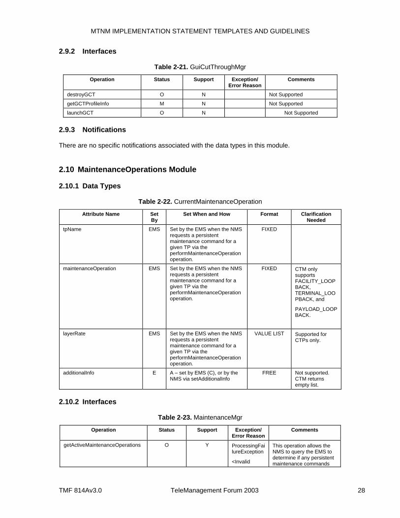
MTNM IMPLEMENTATION STATEMENT TEMPLATES AND GUIDELINES
TMF 814Av3.0 TeleManagement Forum 2003 28
2.9.2 Interfaces
Table 2-21. GuiCutThroughMgr
Operation Status Support Exception/ Error Reason
Comments
destroyGCT O N Not Supported
getGCTProfileInfo M N Not Supported
launchGCT O N Not Supported
2.9.3 Notifications
There are no specific notifications associated with the data types in this module.
2.10 MaintenanceOperations Module
2.10.1 Data Types
Table 2-22. CurrentMaintenanceOperation
Attribute Name Set By
Set When and How Format Clarification Needed
tpName EMS Set by the EMS when the NMS requests a persistent maintenance command for a given TP via the performMaintenanceOperation operation.
FIXED
maintenanceOperation EMS Set by the EMS when the NMS requests a persistent maintenance command for a given TP via the performMaintenanceOperation operation.
FIXED CTM only supports FACILITY_LOOPBACK, TERMINAL_LOOPBACK, and
PAYLOAD_LOOPBACK.
layerRate EMS Set by the EMS when the NMS requests a persistent maintenance command for a given TP via the performMaintenanceOperation operation.
VALUE LIST Supported for CTPs only.
additionalInfo E A – set by EMS (C), or by the NMS via setAdditionalInfo
FREE Not supported. CTM returns empty list.
2.10.2 Interfaces
Table 2-23. MaintenanceMgr
Operation Status Support Exception/ Error Reason
Comments
getActiveMaintenanceOperations O Y ProcessingFailureException
<Invalid
This operation allows the NMS to query the EMS to determine if any persistent maintenance commands
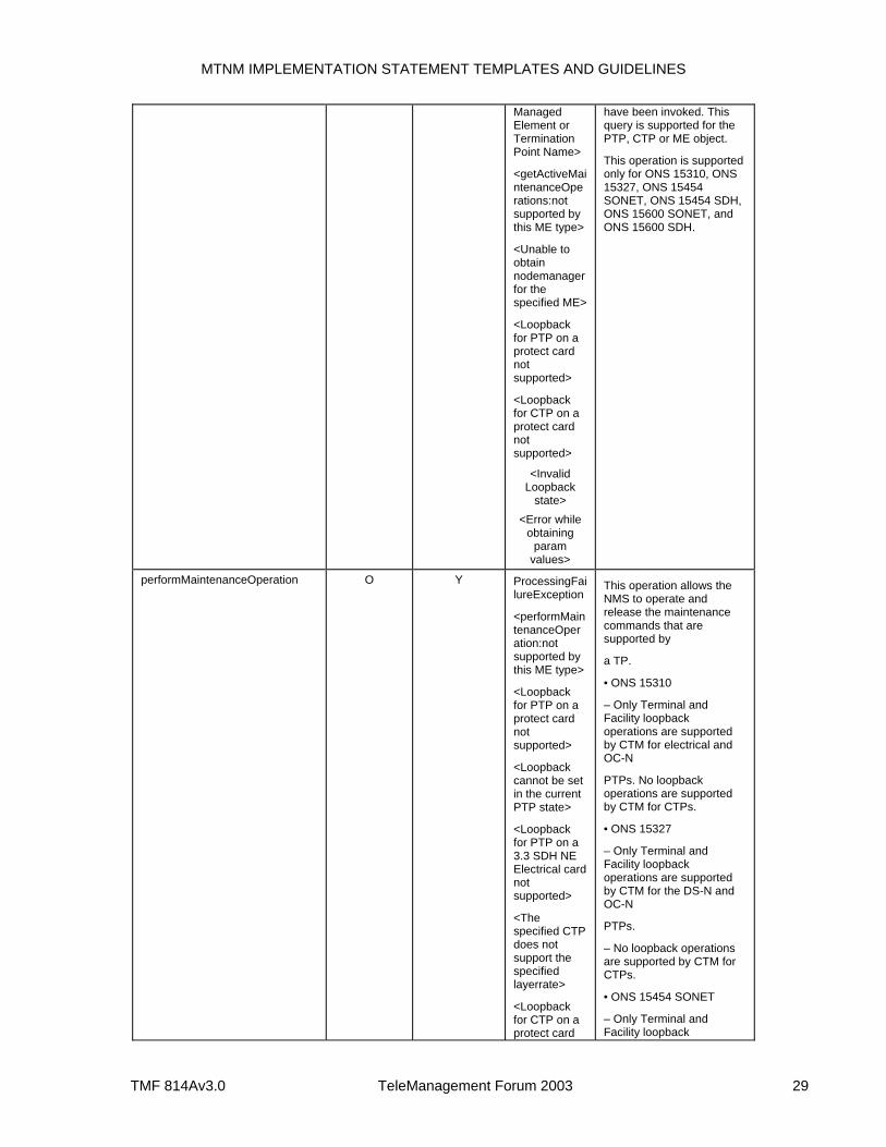
MTNM IMPLEMENTATION STATEMENT TEMPLATES AND GUIDELINES
TMF 814Av3.0 TeleManagement Forum 2003 29
Managed Element or Termination Point Name>
<getActiveMaintenanceOperations:not supported by this ME type>
<Unable to obtain nodemanager for the specified ME>
<Loopback for PTP on a protect card not supported>
<Loopback for CTP on a protect card not supported>
<Invalid Loopback
state> <Error while
obtaining param
values>
have been invoked. This query is supported for the PTP, CTP or ME object.
This operation is supported only for ONS 15310, ONS 15327, ONS 15454 SONET, ONS 15454 SDH, ONS 15600 SONET, and ONS 15600 SDH.
performMaintenanceOperation O Y ProcessingFailureException
<performMaintenanceOperation:not supported by this ME type>
<Loopback for PTP on a protect card not supported>
<Loopback cannot be set in the current PTP state>
<Loopback for PTP on a 3.3 SDH NE Electrical card not supported>
<The specified CTP does not support the specified layerrate>
<Loopback for CTP on a protect card
This operation allows the NMS to operate and release the maintenance commands that are supported by
a TP.
• ONS 15310
– Only Terminal and Facility loopback operations are supported by CTM for electrical and OC-N
PTPs. No loopback operations are supported by CTM for CTPs.
• ONS 15327
– Only Terminal and Facility loopback operations are supported by CTM for the DS-N and OC-N
PTPs.
– No loopback operations are supported by CTM for CTPs.
• ONS 15454 SONET
– Only Terminal and Facility loopback
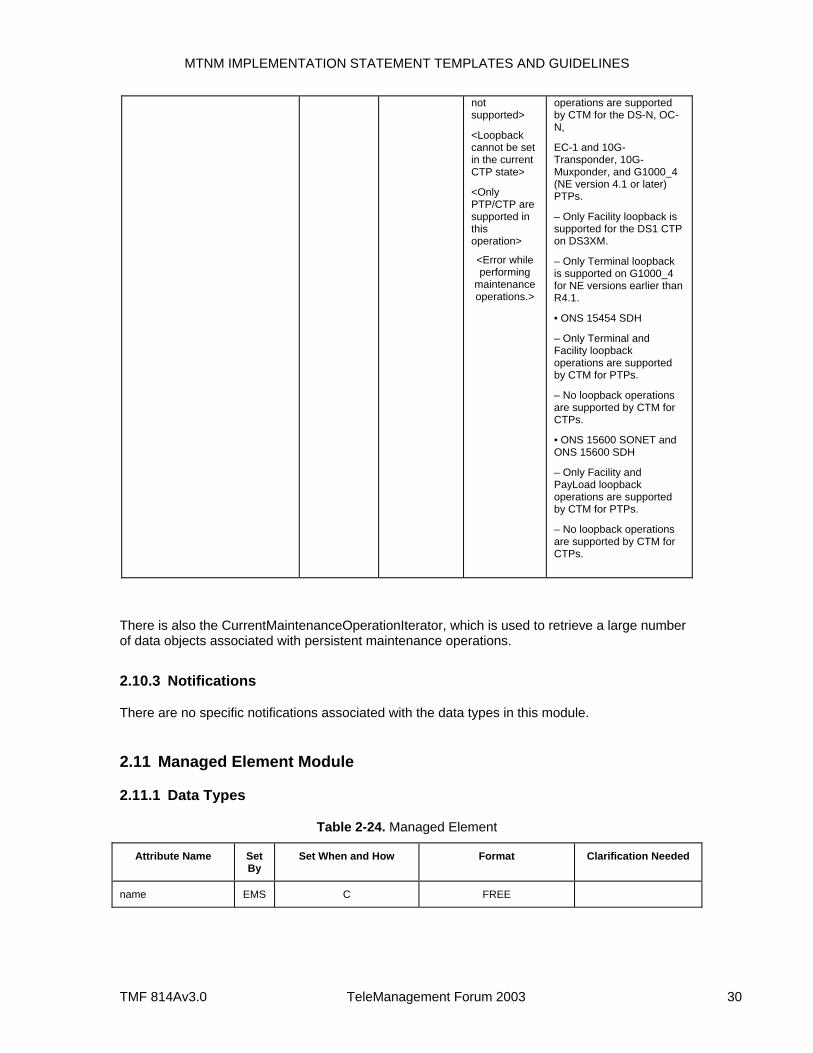
MTNM IMPLEMENTATION STATEMENT TEMPLATES AND GUIDELINES
TMF 814Av3.0 TeleManagement Forum 2003 30
not supported>
<Loopback cannot be set in the current CTP state>
<Only PTP/CTP are supported in this operation>
<Error while performing
maintenance operations.>
operations are supported by CTM for the DS-N, OC-N,
EC-1 and 10G-Transponder, 10G-Muxponder, and G1000_4 (NE version 4.1 or later) PTPs.
– Only Facility loopback is supported for the DS1 CTP on DS3XM.
– Only Terminal loopback is supported on G1000_4 for NE versions earlier than R4.1.
• ONS 15454 SDH
– Only Terminal and Facility loopback operations are supported by CTM for PTPs.
– No loopback operations are supported by CTM for CTPs.
• ONS 15600 SONET and ONS 15600 SDH
– Only Facility and PayLoad loopback operations are supported by CTM for PTPs.
– No loopback operations are supported by CTM for CTPs.
There is also the CurrentMaintenanceOperationIterator, which is used to retrieve a large number of data objects associated with persistent maintenance operations.
2.10.3 Notifications
There are no specific notifications associated with the data types in this module.
2.11 Managed Element Module
2.11.1 Data Types
Table 2-24. Managed Element
Attribute Name Set By
Set When and How Format Clarification Needed
name EMS C FREE
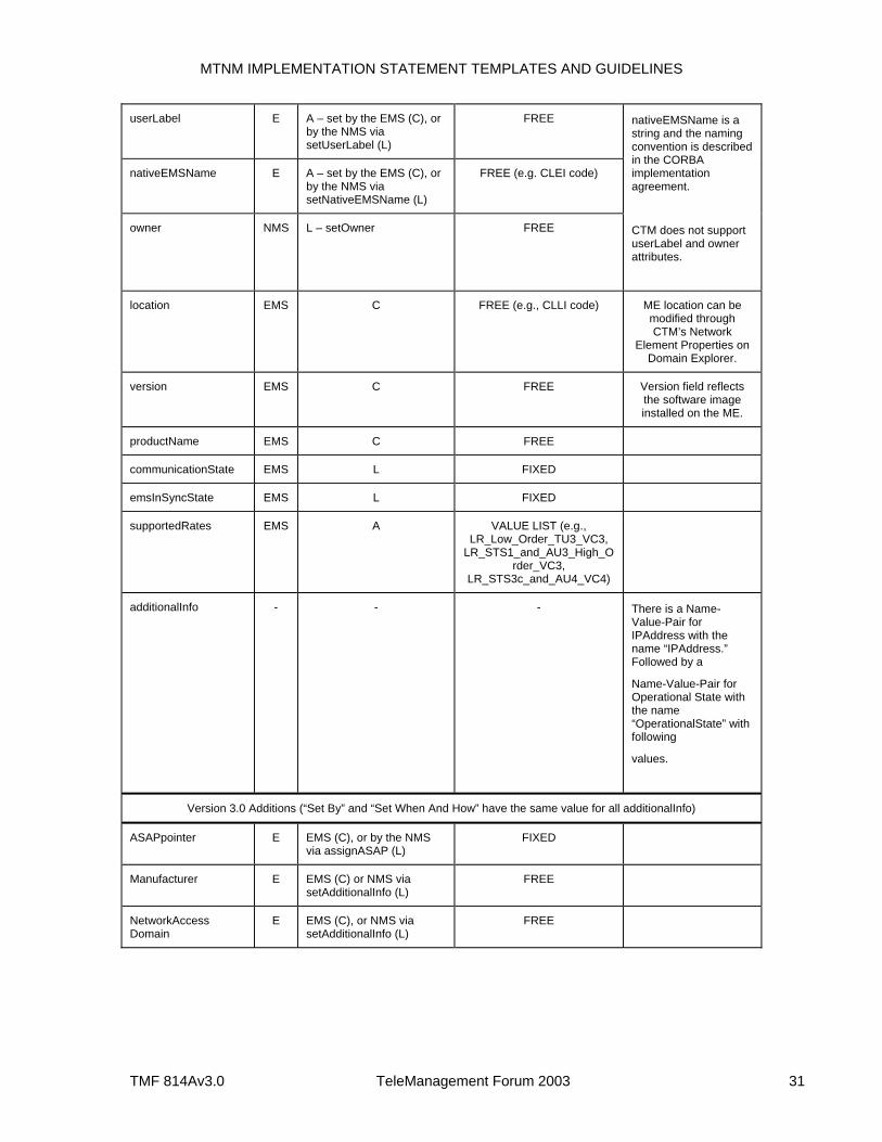
MTNM IMPLEMENTATION STATEMENT TEMPLATES AND GUIDELINES
TMF 814Av3.0 TeleManagement Forum 2003 31
userLabel E A – set by the EMS (C), or by the NMS via setUserLabel (L)
FREE
nativeEMSName E A – set by the EMS (C), or by the NMS via setNativeEMSName (L)
FREE (e.g. CLEI code)
owner NMS L – setOwner FREE
nativeEMSName is a string and the naming convention is described in the CORBA implementation agreement.
CTM does not support userLabel and owner attributes.
location EMS C FREE (e.g., CLLI code) ME location can be modified through CTM’s Network
Element Properties on Domain Explorer.
version EMS C FREE Version field reflects the software image installed on the ME.
productName EMS C FREE
communicationState EMS L FIXED
emsInSyncState EMS L FIXED
supportedRates EMS A VALUE LIST (e.g., LR_Low_Order_TU3_VC3,
LR_STS1_and_AU3_High_Order_VC3,
LR_STS3c_and_AU4_VC4)
additionalInfo - - - There is a Name-Value-Pair for IPAddress with the name “IPAddress.” Followed by a
Name-Value-Pair for Operational State with the name “OperationalState” with following
values.
Version 3.0 Additions (“Set By” and “Set When And How” have the same value for all additionalInfo)
ASAPpointer E EMS (C), or by the NMS via assignASAP (L)
FIXED
Manufacturer E EMS (C) or NMS via setAdditionalInfo (L)
FREE
NetworkAccess Domain
E EMS (C), or NMS via setAdditionalInfo (L)
FREE
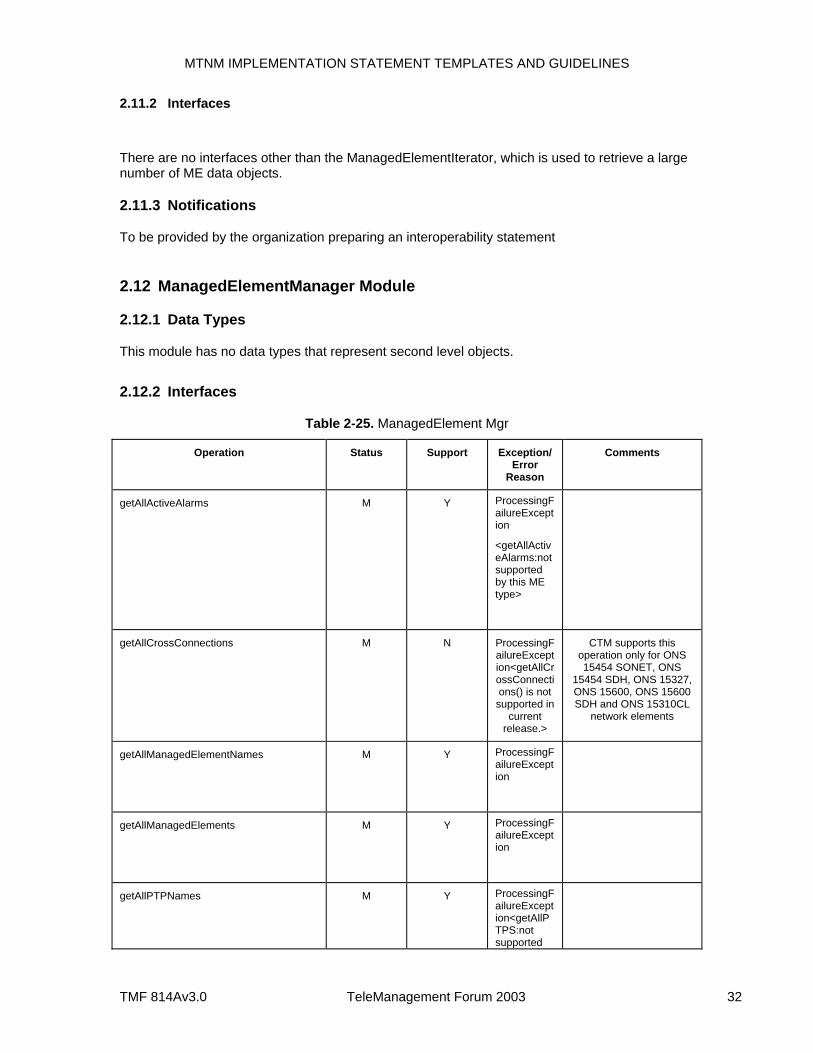
MTNM IMPLEMENTATION STATEMENT TEMPLATES AND GUIDELINES
TMF 814Av3.0 TeleManagement Forum 2003 32
2.11.2 Interfaces
There are no interfaces other than the ManagedElementIterator, which is used to retrieve a large number of ME data objects.
2.11.3 Notifications
To be provided by the organization preparing an interoperability statement
2.12 ManagedElementManager Module
2.12.1 Data Types
This module has no data types that represent second level objects.
2.12.2 Interfaces
Table 2-25. ManagedElement Mgr
Operation Status Support Exception/Error
Reason
Comments
getAllActiveAlarms M Y ProcessingFailureException
<getAllActiveAlarms:not supported by this ME type>
getAllCrossConnections M N ProcessingFailureException<getAllCrossConnections() is not
supported in current
release.>
CTM supports this operation only for ONS 15454 SONET, ONS
15454 SDH, ONS 15327, ONS 15600, ONS 15600 SDH and ONS 15310CL
network elements
getAllManagedElementNames M Y ProcessingFailureException
getAllManagedElements M Y ProcessingFailureException
getAllPTPNames M Y ProcessingFailureException<getAllPTPS:not supported
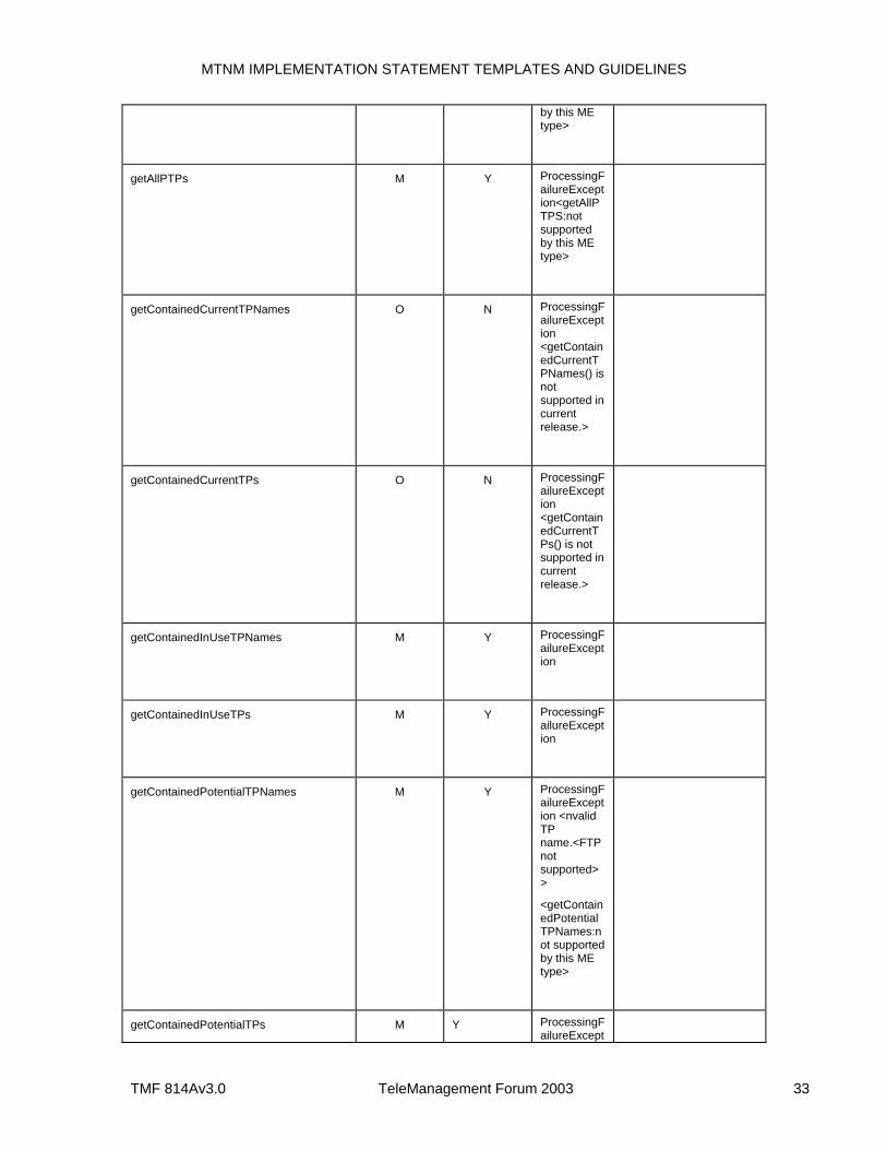
MTNM IMPLEMENTATION STATEMENT TEMPLATES AND GUIDELINES
TMF 814Av3.0 TeleManagement Forum 2003 33
by this ME type>
getAllPTPs M Y ProcessingFailureException<getAllPTPS:not supported by this ME type>
getContainedCurrentTPNames O N ProcessingFailureException <getContainedCurrentTPNames() is not supported in current release.>
getContainedCurrentTPs O N ProcessingFailureException <getContainedCurrentTPs() is not supported in current release.>
getContainedInUseTPNames M Y ProcessingFailureException
getContainedInUseTPs M Y ProcessingFailureException
getContainedPotentialTPNames M Y ProcessingFailureException <nvalid TP name.<FTP not supported>>
<getContainedPotentialTPNames:not supported by this ME type>
getContainedPotentialTPs M Y ProcessingFailureExcept
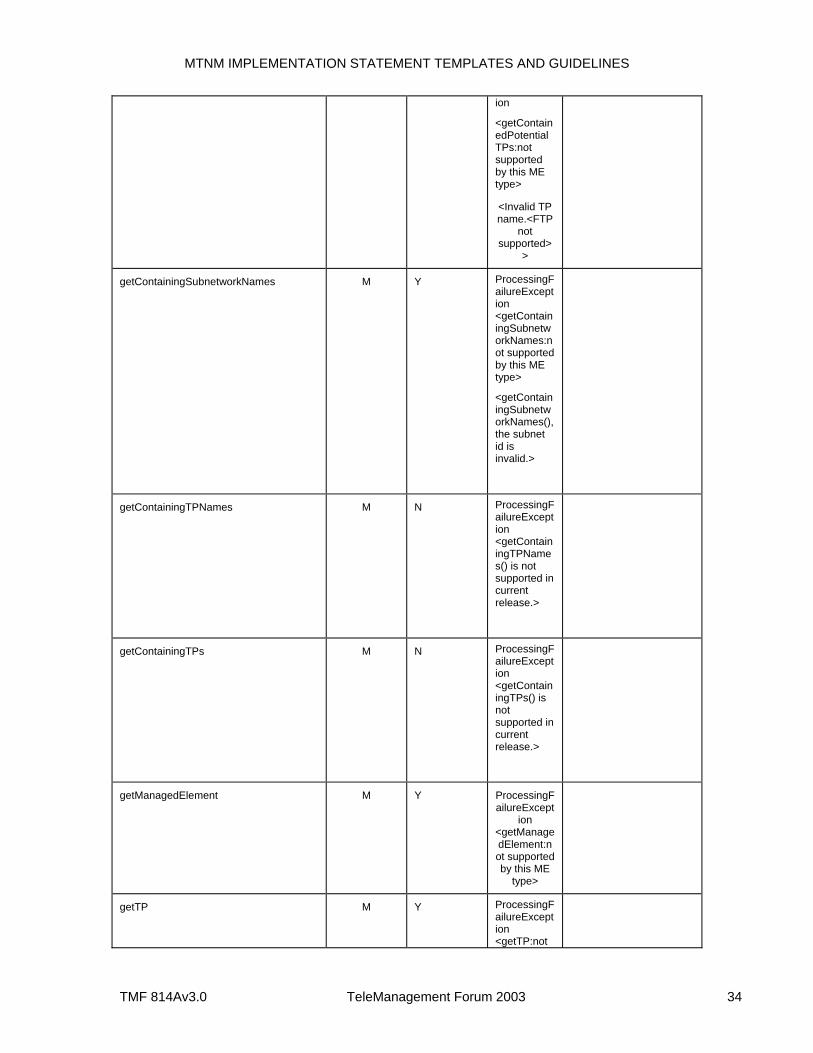
MTNM IMPLEMENTATION STATEMENT TEMPLATES AND GUIDELINES
TMF 814Av3.0 TeleManagement Forum 2003 34
ion
<getContainedPotentialTPs:not supported by this ME type>
<Invalid TP name.<FTP
not supported>
>
getContainingSubnetworkNames M Y ProcessingFailureException <getContainingSubnetworkNames:not supported by this ME type>
<getContainingSubnetworkNames(), the subnet id is invalid.>
getContainingTPNames M N ProcessingFailureException <getContainingTPNames() is not supported in current release.>
getContainingTPs M N ProcessingFailureException <getContainingTPs() is not supported in current release.>
getManagedElement M Y ProcessingFailureExcept
ion <getManagedElement:not supported by this ME
type>
getTP M Y ProcessingFailureException <getTP:not
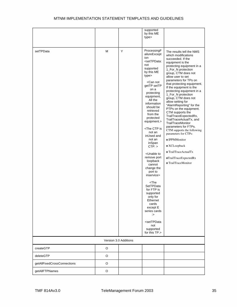
MTNM IMPLEMENTATION STATEMENT TEMPLATES AND GUIDELINES
TMF 814Av3.0 TeleManagement Forum 2003 35
supported by this ME type>
setTPData M Y ProcessingFailureException <setTPData:not supported by this ME type>
<Can not getTP setTP
on a protecting
equipment, All the
information should be retrieved from the protected
equipment.>
<The CTP is not an
inUsed and not an inSpan CTP: >
<Unable to remove port
loopback cannot
change the port to
inservice>
<The SetTPData for FTP is supported
only for Ethernet
cards except E
series cards :>
<setTPData not
supported for this TP.>
The results tell the NMS which modifications succeeded. If the equipment is the protecting equipment in a 1_For_N protection group, CTM does not allow user to set parameters for TPs on that protecting equipment. If the equipment is the protecting equipment in a 1_For_N protection group, CTM does not allow setting for “AlarmReporting” for the PTPs on the equipment. CTM supports the TrailTraceExpectedRx, TrailTraceActualTx, and TrailTraceMonitor parameters for FTPs. CTM supports the following parameters for CTPs:
o IPPMMonitor
o XCLoopback
o TrailTraceActualTx
oTrailTraceExpectedRx
o TrailTraceMonitor
Version 3.0 Additions
createGTP O
deleteGTP O
getAllFixedCrossConnections O
getAllFTPNames O
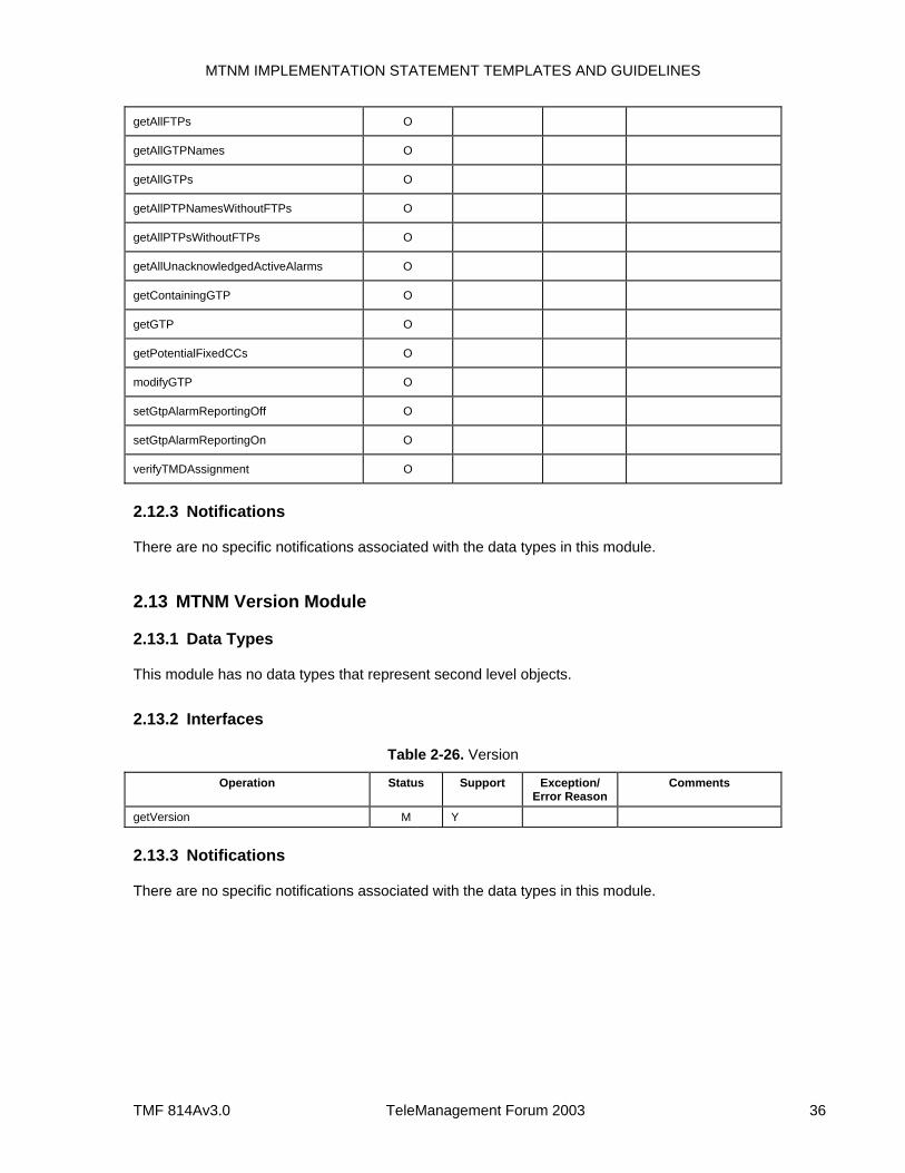
MTNM IMPLEMENTATION STATEMENT TEMPLATES AND GUIDELINES
TMF 814Av3.0 TeleManagement Forum 2003 36
getAllFTPs O
getAllGTPNames O
getAllGTPs O
getAllPTPNamesWithoutFTPs O
getAllPTPsWithoutFTPs O
getAllUnacknowledgedActiveAlarms O
getContainingGTP O
getGTP O
getPotentialFixedCCs O
modifyGTP O
setGtpAlarmReportingOff O
setGtpAlarmReportingOn O
verifyTMDAssignment O
2.12.3 Notifications
There are no specific notifications associated with the data types in this module.
2.13 MTNM Version Module
2.13.1 Data Types
This module has no data types that represent second level objects.
2.13.2 Interfaces
Table 2-26. Version
Operation Status Support Exception/ Error Reason
Comments
getVersion M Y
2.13.3 Notifications
There are no specific notifications associated with the data types in this module.
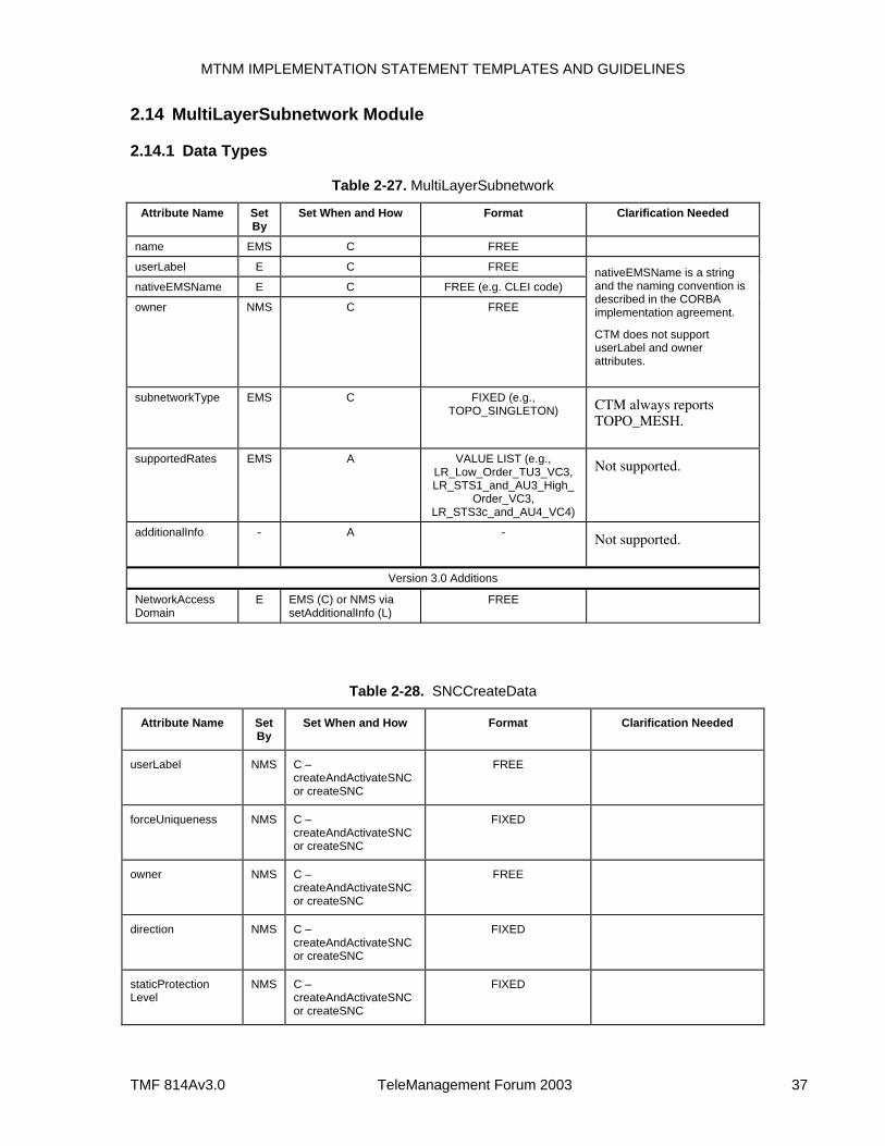
MTNM IMPLEMENTATION STATEMENT TEMPLATES AND GUIDELINES
TMF 814Av3.0 TeleManagement Forum 2003 37
2.14 MultiLayerSubnetwork Module
2.14.1 Data Types
Table 2-27. MultiLayerSubnetwork
Attribute Name Set By
Set When and How Format Clarification Needed
name EMS C FREE
userLabel E C FREE
nativeEMSName E C FREE (e.g. CLEI code)
owner NMS C FREE
nativeEMSName is a string and the naming convention is described in the CORBA implementation agreement.
CTM does not support userLabel and owner attributes.
subnetworkType EMS C FIXED (e.g., TOPO_SINGLETON) CTM always reports
TOPO_MESH.
supportedRates EMS A VALUE LIST (e.g., LR_Low_Order_TU3_VC3, LR_STS1_and_AU3_High_
Order_VC3, LR_STS3c_and_AU4_VC4)
Not supported.
additionalInfo - A - Not supported.
Version 3.0 Additions
NetworkAccess Domain
E EMS (C) or NMS via setAdditionalInfo (L)
FREE
Table 2-28. SNCCreateData
Attribute Name Set By
Set When and How Format Clarification Needed
userLabel NMS C – createAndActivateSNC or createSNC
FREE
forceUniqueness NMS C – createAndActivateSNC or createSNC
FIXED
owner NMS C – createAndActivateSNC or createSNC
FREE
direction NMS C – createAndActivateSNC or createSNC
FIXED
staticProtection Level
NMS C – createAndActivateSNC or createSNC
FIXED
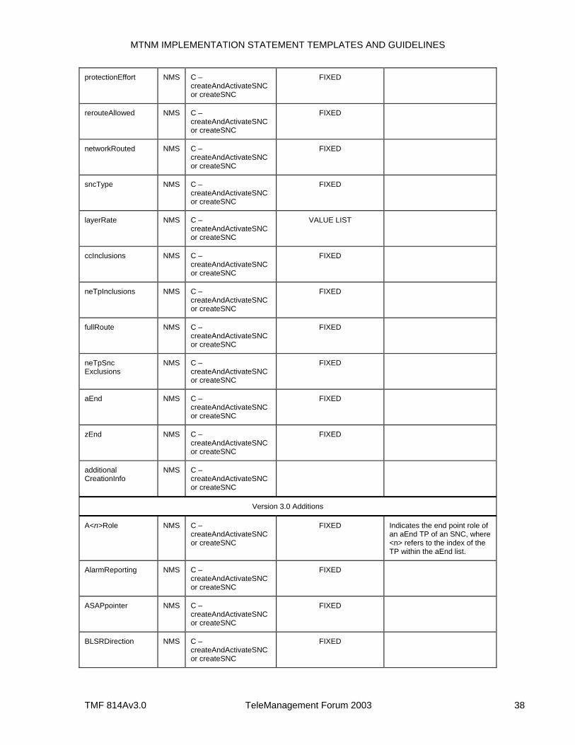
MTNM IMPLEMENTATION STATEMENT TEMPLATES AND GUIDELINES
TMF 814Av3.0 TeleManagement Forum 2003 38
protectionEffort NMS C – createAndActivateSNC or createSNC
FIXED
rerouteAllowed NMS C – createAndActivateSNC or createSNC
FIXED
networkRouted NMS C – createAndActivateSNC or createSNC
FIXED
sncType NMS C – createAndActivateSNC or createSNC
FIXED
layerRate NMS C – createAndActivateSNC or createSNC
VALUE LIST
ccInclusions NMS C – createAndActivateSNC or createSNC
FIXED
neTpInclusions NMS C – createAndActivateSNC or createSNC
FIXED
fullRoute NMS C – createAndActivateSNC or createSNC
FIXED
neTpSnc Exclusions
NMS C – createAndActivateSNC or createSNC
FIXED
aEnd NMS C – createAndActivateSNC or createSNC
FIXED
zEnd NMS C – createAndActivateSNC or createSNC
FIXED
additional CreationInfo
NMS C – createAndActivateSNC or createSNC
Version 3.0 Additions
A<n>Role NMS C – createAndActivateSNC or createSNC
FIXED Indicates the end point role of an aEnd TP of an SNC, where <n> refers to the index of the TP within the aEnd list.
AlarmReporting NMS C – createAndActivateSNC or createSNC
FIXED
ASAPpointer NMS C – createAndActivateSNC or createSNC
FIXED
BLSRDirection NMS C – createAndActivateSNC or createSNC
FIXED
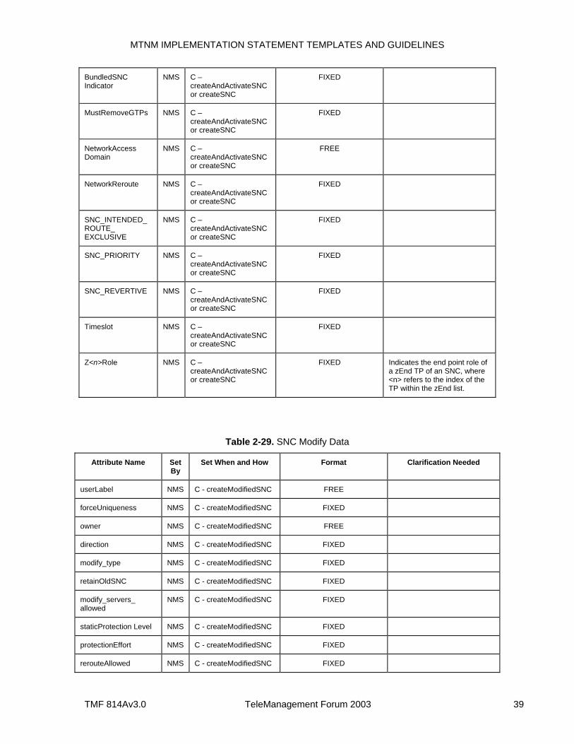
MTNM IMPLEMENTATION STATEMENT TEMPLATES AND GUIDELINES
TMF 814Av3.0 TeleManagement Forum 2003 39
BundledSNC Indicator
NMS C – createAndActivateSNC or createSNC
FIXED
MustRemoveGTPs NMS C – createAndActivateSNC or createSNC
FIXED
NetworkAccess Domain
NMS C – createAndActivateSNC or createSNC
FREE
NetworkReroute NMS C – createAndActivateSNC or createSNC
FIXED
SNC_INTENDED_ROUTE_ EXCLUSIVE
NMS C – createAndActivateSNC or createSNC
FIXED
SNC_PRIORITY NMS C – createAndActivateSNC or createSNC
FIXED
SNC_REVERTIVE NMS C – createAndActivateSNC or createSNC
FIXED
Timeslot NMS C – createAndActivateSNC or createSNC
FIXED
Z<n>Role NMS C – createAndActivateSNC or createSNC
FIXED Indicates the end point role of a zEnd TP of an SNC, where <n> refers to the index of the TP within the zEnd list.
Table 2-29. SNC Modify Data
Attribute Name Set By
Set When and How Format Clarification Needed
userLabel NMS C - createModifiedSNC FREE
forceUniqueness NMS C - createModifiedSNC FIXED
owner NMS C - createModifiedSNC FREE
direction NMS C - createModifiedSNC FIXED
modify_type NMS C - createModifiedSNC FIXED
retainOldSNC NMS C - createModifiedSNC FIXED
modify_servers_ allowed
NMS C - createModifiedSNC FIXED
staticProtection Level NMS C - createModifiedSNC FIXED
protectionEffort NMS C - createModifiedSNC FIXED
rerouteAllowed NMS C - createModifiedSNC FIXED
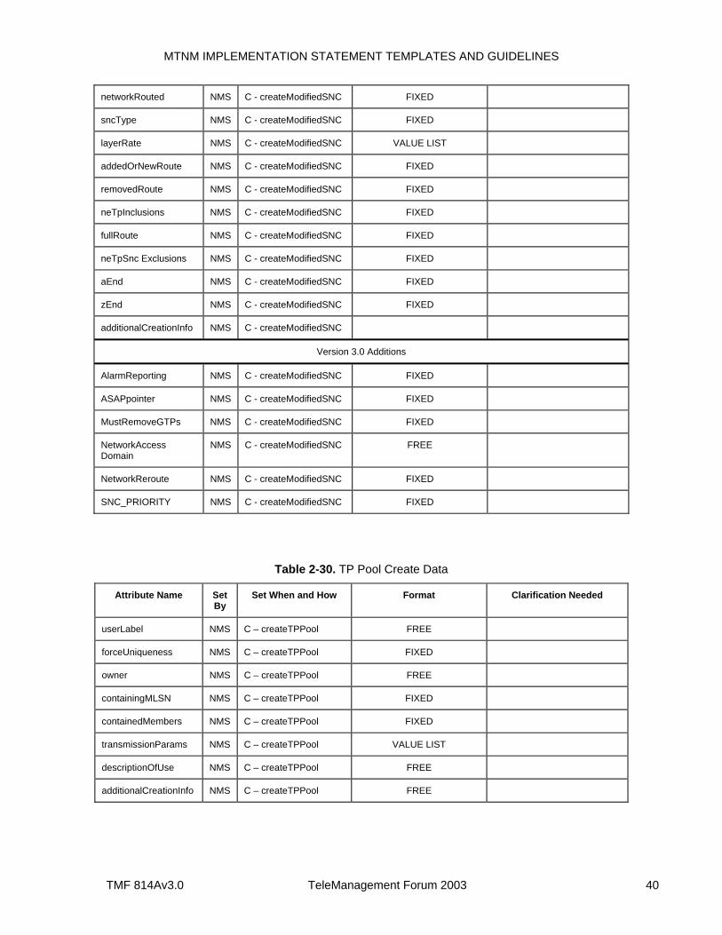
MTNM IMPLEMENTATION STATEMENT TEMPLATES AND GUIDELINES
TMF 814Av3.0 TeleManagement Forum 2003 40
networkRouted NMS C - createModifiedSNC FIXED
sncType NMS C - createModifiedSNC FIXED
layerRate NMS C - createModifiedSNC VALUE LIST
addedOrNewRoute NMS C - createModifiedSNC FIXED
removedRoute NMS C - createModifiedSNC FIXED
neTpInclusions NMS C - createModifiedSNC FIXED
fullRoute NMS C - createModifiedSNC FIXED
neTpSnc Exclusions NMS C - createModifiedSNC FIXED
aEnd NMS C - createModifiedSNC FIXED
zEnd NMS C - createModifiedSNC FIXED
additionalCreationInfo NMS C - createModifiedSNC
Version 3.0 Additions
AlarmReporting NMS C - createModifiedSNC FIXED
ASAPpointer NMS C - createModifiedSNC FIXED
MustRemoveGTPs NMS C - createModifiedSNC FIXED
NetworkAccess Domain
NMS C - createModifiedSNC FREE
NetworkReroute NMS C - createModifiedSNC FIXED
SNC_PRIORITY NMS C - createModifiedSNC FIXED
Table 2-30. TP Pool Create Data
Attribute Name Set By
Set When and How Format Clarification Needed
userLabel NMS C – createTPPool FREE
forceUniqueness NMS C – createTPPool FIXED
owner NMS C – createTPPool FREE
containingMLSN NMS C – createTPPool FIXED
containedMembers NMS C – createTPPool FIXED
transmissionParams NMS C – createTPPool VALUE LIST
descriptionOfUse NMS C – createTPPool FREE
additionalCreationInfo NMS C – createTPPool FREE
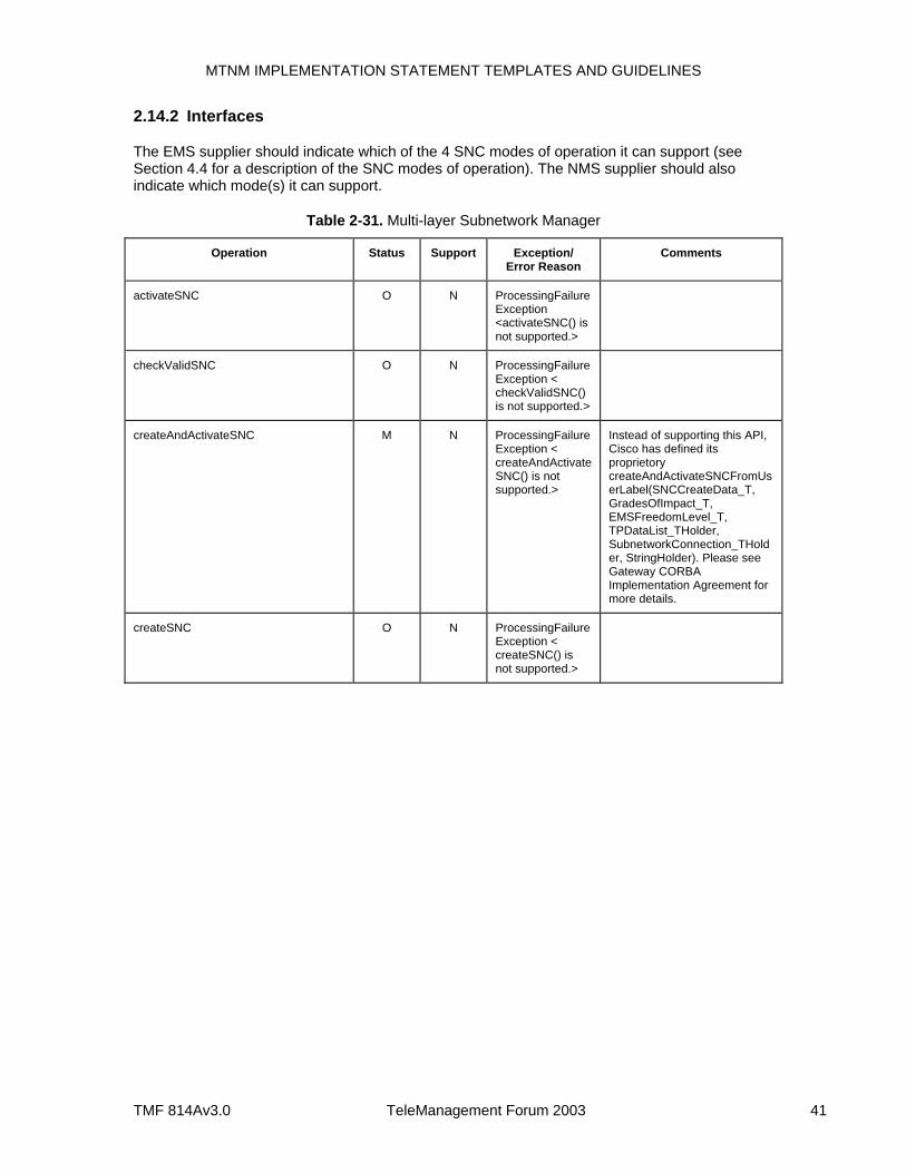
MTNM IMPLEMENTATION STATEMENT TEMPLATES AND GUIDELINES
TMF 814Av3.0 TeleManagement Forum 2003 41
2.14.2 Interfaces
The EMS supplier should indicate which of the 4 SNC modes of operation it can support (see Section 4.4 for a description of the SNC modes of operation). The NMS supplier should also indicate which mode(s) it can support.
Table 2-31. Multi-layer Subnetwork Manager
Operation Status Support Exception/ Error Reason
Comments
activateSNC O N ProcessingFailureException <activateSNC() is not supported.>
checkValidSNC O N ProcessingFailureException < checkValidSNC() is not supported.>
createAndActivateSNC M N ProcessingFailureException < createAndActivateSNC() is not supported.>
Instead of supporting this API, Cisco has defined its proprietory createAndActivateSNCFromUserLabel(SNCCreateData_T, GradesOfImpact_T, EMSFreedomLevel_T, TPDataList_THolder, SubnetworkConnection_THolder, StringHolder). Please see Gateway CORBA Implementation Agreement for more details.
createSNC O N ProcessingFailureException < createSNC() is not supported.>
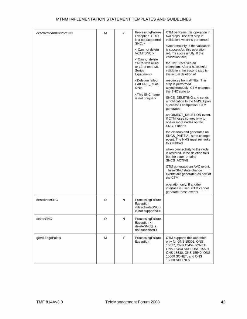
MTNM IMPLEMENTATION STATEMENT TEMPLATES AND GUIDELINES
TMF 814Av3.0 TeleManagement Forum 2003 42
deactivateAndDeleteSNC M Y ProcessingFailureException < This is a not supported SNC.>
< Can not delete VCAT SNC.>
< Cannot delete SNCs with aEnd or zEnd on a ML-Series Equipment>
<Deletion failed: FAILURE_REASON>
<This SNC name is not unique:>
CTM performs this operation in two steps. The first step is validation, which is performed
synchronously. If the validation is successful, this operation returns successfully. If the validation fails,
the NMS receives an exception. After a successful validation, the second step is the actual deletion of
resources from all NEs. This step is performed asynchronously. CTM changes the SNC state to
SNCS_DELETING and sends a notification to the NMS. Upon successful completion, CTM generates
an OBJECT_DELETION event. If CTM loses connectivity to one or more nodes on the SNC, it aborts
the cleanup and generates an SNCS_PARTIAL state change event. The NMS must reinvoke this method
when connectivity to the node is restored. If the deletion fails but the state remains SNCS_ACTIVE,
CTM generates an AVC event. These SNC state change events are generated as part of the CTM
operation only. If another interface is used, CTM cannot generate these events.
deactivateSNC O N ProcessingFailureException <deactivateSNC() is not supported.>
deleteSNC O N ProcessingFailureException < deleteSNC() is not supported.>
getAllEdgePoints M Y ProcessingFailureException
CTM supports this operation only for ONS 15301, ONS 15327, ONS 15454 SONET, ONS 15454 SDH, ONS 15501, ONS 15530, ONS 15540, ONS 15600 SONET, and ONS 15600 SDH NEs
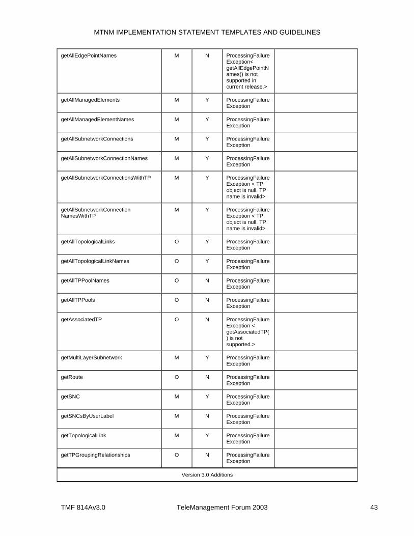
MTNM IMPLEMENTATION STATEMENT TEMPLATES AND GUIDELINES
TMF 814Av3.0 TeleManagement Forum 2003 43
getAllEdgePointNames M N ProcessingFailureException< getAllEdgePointNames() is not supported in current release.>
getAllManagedElements M Y ProcessingFailureException
getAllManagedElementNames M Y ProcessingFailureException
getAllSubnetworkConnections M Y ProcessingFailureException
getAllSubnetworkConnectionNames M Y ProcessingFailureException
getAllSubnetworkConnectionsWithTP M Y ProcessingFailureException < TP object is null. TP name is invalid>
getAllSubnetworkConnection NamesWithTP
M Y ProcessingFailureException < TP object is null. TP name is invalid>
getAllTopologicalLinks O Y ProcessingFailureException
getAllTopologicalLinkNames O Y ProcessingFailureException
getAllTPPoolNames O N ProcessingFailureException
getAllTPPools O N ProcessingFailureException
getAssociatedTP O N ProcessingFailureException < getAssociatedTP() is not supported.>
getMultiLayerSubnetwork M Y ProcessingFailureException
getRoute O N ProcessingFailureException
getSNC M Y ProcessingFailureException
getSNCsByUserLabel M N ProcessingFailureException
getTopologicalLink M Y ProcessingFailureException
getTPGroupingRelationships O N ProcessingFailureException
Version 3.0 Additions
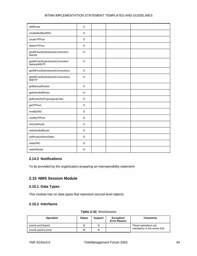
MTNM IMPLEMENTATION STATEMENT TEMPLATES AND GUIDELINES
TMF 814Av3.0 TeleManagement Forum 2003 44
addRoute O
createModifiedSNC O
createTPPool O
deleteTPPool O
getAllFixedSubnetworkConnection Names
O
getAllFixedSubnetworkConnection NamesWithTP
O
getAllFixedSubnetworkConnections O
getAllFixedSubnetworkConnections WithTP
O
getBackupRoutes O
getIntendedRoute O
getRouteAndTopologicalLinks O
getTPPool O
modifySNC O
modifyTPPool O
removeRoute O
setIntendedRoute O
setRoutesAdminState O
swapSNC O
switchRoute O
2.14.3 Notifications
To be provided by the organization preparing an interoperability statement
2.15 NMS Session Module
2.15.1 Data Types
This module has no data types that represent second level objects.
2.15.2 Interfaces
Table 2-32. NmsSession
Operation Status Support Exception/ Error Reason
Comments
eventLossCleared M N
eventLossOccurred M N
These operations are mandatory in the sense that
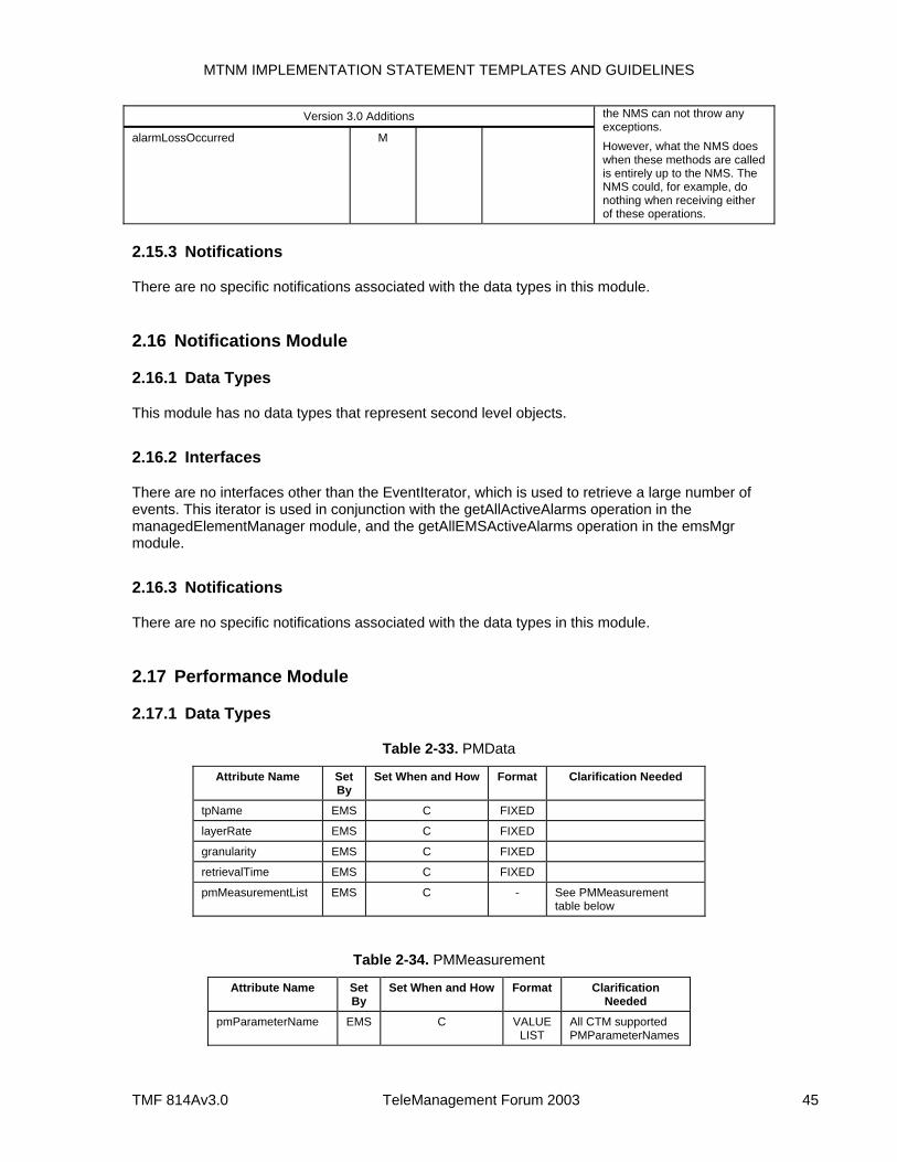
MTNM IMPLEMENTATION STATEMENT TEMPLATES AND GUIDELINES
TMF 814Av3.0 TeleManagement Forum 2003 45
Version 3.0 Additions
alarmLossOccurred M
the NMS can not throw any exceptions. However, what the NMS does when these methods are called is entirely up to the NMS. The NMS could, for example, do nothing when receiving either of these operations.
2.15.3 Notifications
There are no specific notifications associated with the data types in this module.
2.16 Notifications Module
2.16.1 Data Types
This module has no data types that represent second level objects.
2.16.2 Interfaces
There are no interfaces other than the EventIterator, which is used to retrieve a large number of events. This iterator is used in conjunction with the getAllActiveAlarms operation in the managedElementManager module, and the getAllEMSActiveAlarms operation in the emsMgr module.
2.16.3 Notifications
There are no specific notifications associated with the data types in this module.
2.17 Performance Module
2.17.1 Data Types
Table 2-33. PMData
Attribute Name Set By
Set When and How Format Clarification Needed
tpName EMS C FIXED
layerRate EMS C FIXED
granularity EMS C FIXED
retrievalTime EMS C FIXED
pmMeasurementList EMS C - See PMMeasurement table below
Table 2-34. PMMeasurement
Attribute Name Set By
Set When and How Format Clarification Needed
pmParameterName EMS C VALUE LIST
All CTM supported PMParameterNames
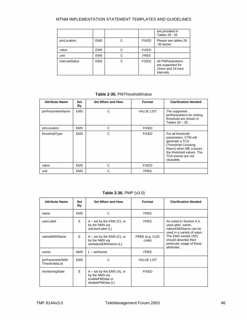
MTNM IMPLEMENTATION STATEMENT TEMPLATES AND GUIDELINES
TMF 814Av3.0 TeleManagement Forum 2003 46
are provided in Tables 29 - 35
pmLocation EMS C FIXED Please see tables 29 -35 below.
value EMS C FIXED
unit EMS C FREE
intervalStatus EMS C FIXED All PMParameters are supported for 15min and 24 hour intervals.
Table 2-35. PMThresholdValue
Attribute Name Set By
Set When and How Format Clarification Needed
pmParameterName EMS C VALUE LIST The supported pmParameters for setting threshold are shown in Tables 29 – 35.
pmLocation EMS C FIXED
thresholdType EMS C FIXED For all threshold parameters, CTM will generate a TCA (Threshold Crossing Alarm) when ME crosses the threshold values. The TCA events are not clearable.
value EMS C FIXED
unit EMS C FREE
Table 2-36. PMP (v3.0)
Attribute Name Set By
Set When and How Format Clarification Needed
name EMS C FREE
userLabel E A – set by the EMS (C), or by the NMS via setUserLabel (L)
FREE
nativeEMSName E A – set by the EMS (C), or by the NMS via setNativeEMSName (L)
FREE (e.g. CLEI code)
owner NMS L – setOwner FREE
As noted in Section 4.3, userLabel, owner, nativeEMSName can be used in a variety of ways. The EMS vendor (SP) should describe their particular usage of these attributes.
pmParameterWith ThresholdsList
EMS C VALUE LIST
monitoringState E A – set by the EMS (A), or by the NMS via enablePMData or disablePMData (L)
FIXED
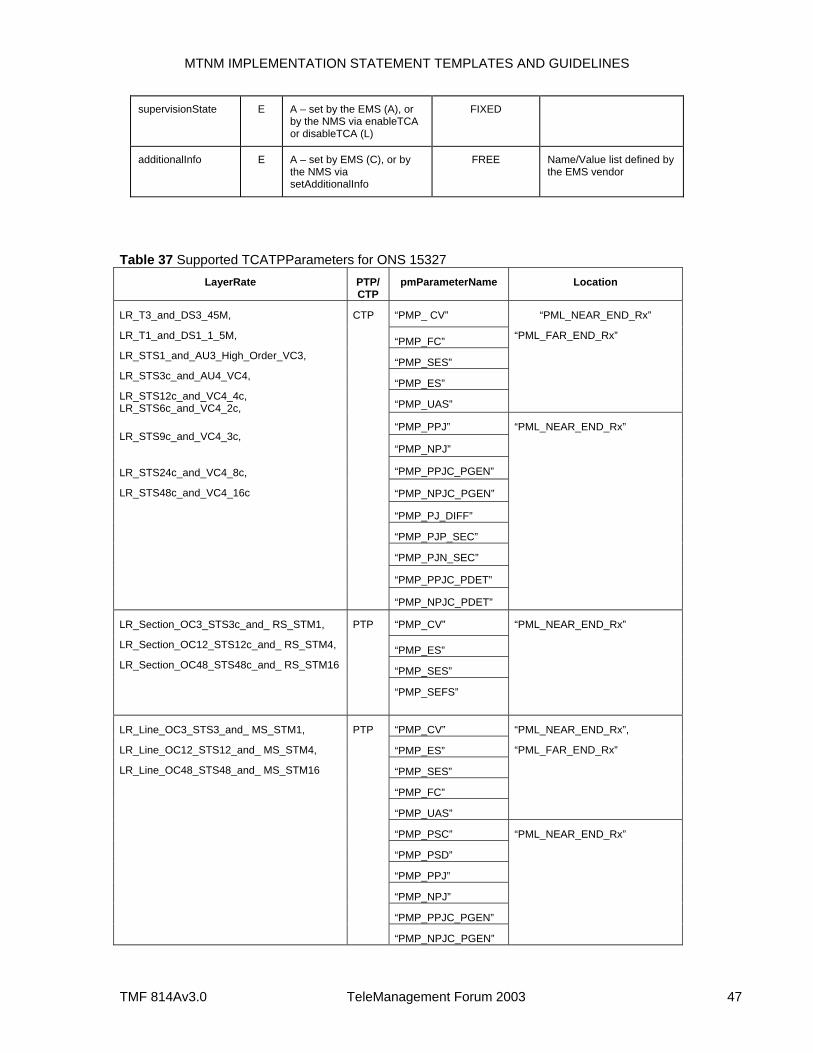
MTNM IMPLEMENTATION STATEMENT TEMPLATES AND GUIDELINES
TMF 814Av3.0 TeleManagement Forum 2003 47
supervisionState E A – set by the EMS (A), or by the NMS via enableTCA or disableTCA (L)
FIXED
additionalInfo E A – set by EMS (C), or by the NMS via setAdditionalInfo
FREE Name/Value list defined by the EMS vendor
Table 37 Supported TCATPParameters for ONS 15327 LayerRate PTP/
CTP pmParameterName Location
“PMP_ CV”
“PMP_FC”
“PMP_SES”
“PMP_ES”
“PMP_UAS”
“PML_NEAR_END_Rx”
“PML_FAR_END_Rx”
“PMP_PPJ”
“PMP_NPJ”
“PMP_PPJC_PGEN”
“PMP_NPJC_PGEN”
“PMP_PJ_DIFF”
“PMP_PJP_SEC”
“PMP_PJN_SEC”
“PMP_PPJC_PDET”
LR_T3_and_DS3_45M,
LR_T1_and_DS1_1_5M,
LR_STS1_and_AU3_High_Order_VC3,
LR_STS3c_and_AU4_VC4,
LR_STS12c_and_VC4_4c, LR_STS6c_and_VC4_2c,
LR_STS9c_and_VC4_3c,
LR_STS24c_and_VC4_8c,
LR_STS48c_and_VC4_16c
CTP
“PMP_NPJC_PDET”
“PML_NEAR_END_Rx”
“PMP_CV”
“PMP_ES”
“PMP_SES”
LR_Section_OC3_STS3c_and_ RS_STM1,
LR_Section_OC12_STS12c_and_ RS_STM4,
LR_Section_OC48_STS48c_and_ RS_STM16
PTP
“PMP_SEFS”
“PML_NEAR_END_Rx”
“PMP_CV”
“PMP_ES”
“PMP_SES”
“PMP_FC”
“PMP_UAS”
“PML_NEAR_END_Rx”,
“PML_FAR_END_Rx”
“PMP_PSC”
“PMP_PSD”
“PMP_PPJ”
“PMP_NPJ”
“PMP_PPJC_PGEN”
LR_Line_OC3_STS3_and_ MS_STM1,
LR_Line_OC12_STS12_and_ MS_STM4,
LR_Line_OC48_STS48_and_ MS_STM16
PTP
“PMP_NPJC_PGEN”
“PML_NEAR_END_Rx”
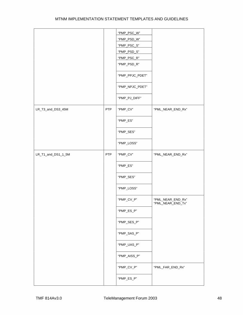
MTNM IMPLEMENTATION STATEMENT TEMPLATES AND GUIDELINES
TMF 814Av3.0 TeleManagement Forum 2003 48
“PMP_PSC_W”
“PMP_PSD_W”
“PMP_PSC_S”
“PMP_PSD_S”
“PMP_PSC_R”
“PMP_PSD_R”
“PMP_PPJC_PDET”
“PMP_NPJC_PDET”
“PMP_PJ_DIFF”
“PMP_CV”
“PMP_ES”
“PMP_SES”
LR_T3_and_DS3_45M PTP
“PMP_LOSS”
“PML_NEAR_END_Rx”
“PMP_CV”
“PMP_ES”
“PMP_SES”
“PMP_LOSS”
“PML_NEAR_END_Rx”
“PMP_CV_P”
“PMP_ES_P”
“PMP_SES_P”
“PMP_SAS_P”
“PMP_UAS_P”
“PMP_AISS_P”
“PML_NEAR_END_Rx” “PML_NEAR_END_Tx”
“PMP_CV_P”
LR_T1_and_DS1_1_5M
PTP
“PMP_ES_P”
“PML_FAR_END_Rx”
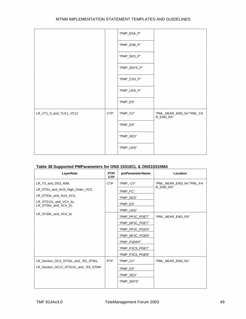
MTNM IMPLEMENTATION STATEMENT TEMPLATES AND GUIDELINES
TMF 814Av3.0 TeleManagement Forum 2003 49
“PMP_ESA_P”
“PMP_ESB_P”
“PMP_SES_P”
“PMP_SEFS_P”
“PMP_CSS_P”
“PMP_UAS_P”
“PMP_ES”
“PMP_CV”
“PMP_ES”
“PMP_SES”
LR_VT1_5_and_TU11_VC11 CTP
“PMP_UAS”
“PML_NEAR_END_Rx”“PML_FAR_END_RX”
Table 38 Supported PMParameters for ONS 15310CL & ONS15310MA LayerRate PTP/
CTP pmParameterName Location
“PMP_ CV”
“PMP_FC”
“PMP_SES”
“PMP_ES”
CTP
“PMP_UAS”
“PML_NEAR_END_Rx”“PML_FAR_END_RX”
“PMP_PPJC_PDET”
“PMP_NPJC_PDET”
“PMP_PPJC_PGEN”
“PMP_NPJC_PGEN”
“PMP_PJDIFF”
“PMP_PJCS_PDET”
LR_T3_and_DS3_45M,
LR_STS1_and_AU3_High_Order_VC3,
LR_STS3c_and_AU4_VC4,
LR_STS12c_and_VC4_4c, LR_STS6c_and_VC4_2c,
LR_STS9c_and_VC4_3c
“PMP_PJCS_PGEN”
“PML_NEAR_END_RX”
“PMP_CV”
“PMP_ES”
“PMP_SES”
LR_Section_OC3_STS3c_and_ RS_STM1,
LR_Section_OC12_STS12c_and_ RS_STM4
PTP
“PMP_SEFS”
“PML_NEAR_END_Rx”
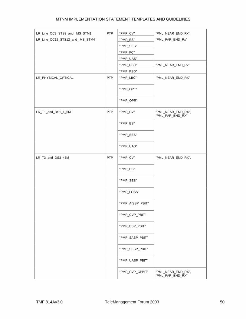
MTNM IMPLEMENTATION STATEMENT TEMPLATES AND GUIDELINES
TMF 814Av3.0 TeleManagement Forum 2003 50
“PMP_CV”
“PMP_ES”
“PMP_SES”
“PMP_FC”
“PMP_UAS”
“PML_NEAR_END_Rx”,
“PML_FAR_END_Rx”
“PMP_PSC”
LR_Line_OC3_STS3_and_ MS_STM1,
LR_Line_OC12_STS12_and_ MS_STM4
PTP
“PMP_PSD”
“PML_NEAR_END_Rx”
“PMP_LBC”
“PMP_OPT”
LR_PHYSICAL_OPTICAL PTP
“PMP_OPR”
“PML_NEAR_END_RX”
“PMP_CV”
“PMP_ES”
“PMP_SES”
LR_T1_and_DS1_1_5M PTP
“PMP_UAS”
“PML_NEAR_END_RX”, “PML_FAR_END_RX”
“PMP_CV”
“PMP_ES”
“PMP_SES”
“PMP_LOSS”
“PMP_AISSP_PBIT”
“PMP_CVP_PBIT”
“PMP_ESP_PBIT”
“PMP_SASP_PBIT”
“PMP_SESP_PBIT”
“PMP_UASP_PBIT”
“PML_NEAR_END_RX”,
LR_T3_and_DS3_45M PTP
“PMP_CVP_CPBIT” “PML_NEAR_END_RX”, “PML_FAR_END_RX”
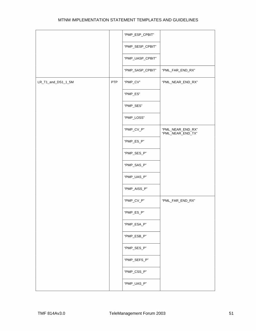
MTNM IMPLEMENTATION STATEMENT TEMPLATES AND GUIDELINES
TMF 814Av3.0 TeleManagement Forum 2003 51
“PMP_ESP_CPBIT”
“PMP_SESP_CPBIT”
“PMP_UASP_CPBIT”
“PMP_SASP_CPBIT” “PML_FAR_END_RX”
“PMP_CV”
“PMP_ES”
“PMP_SES”
“PMP_LOSS”
“PML_NEAR_END_RX”
“PMP_CV_P”
“PMP_ES_P”
“PMP_SES_P”
“PMP_SAS_P”
“PMP_UAS_P”
“PMP_AISS_P”
“PML_NEAR_END_RX” “PML_NEAR_END_TX”
“PMP_CV_P”
“PMP_ES_P”
“PMP_ESA_P”
“PMP_ESB_P”
“PMP_SES_P”
“PMP_SEFS_P”
“PMP_CSS_P”
LR_T1_and_DS1_1_5M PTP
“PMP_UAS_P”
“PML_FAR_END_RX”
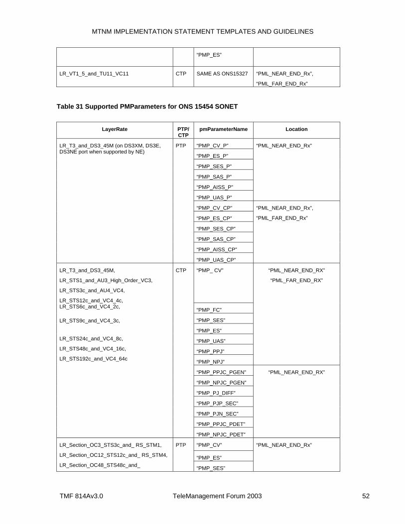
MTNM IMPLEMENTATION STATEMENT TEMPLATES AND GUIDELINES
TMF 814Av3.0 TeleManagement Forum 2003 52
“PMP_ES”
LR_VT1_5_and_TU11_VC11 CTP SAME AS ONS15327 “PML_NEAR_END_Rx”,
“PML_FAR_END_Rx”
Table 31 Supported PMParameters for ONS 15454 SONET
LayerRate PTP/
CTP pmParameterName Location
“PMP_CV_P”
“PMP_ES_P”
“PMP_SES_P”
“PMP_SAS_P”
“PMP_AISS_P”
“PMP_UAS_P”
“PML_NEAR_END_Rx”
“PMP_CV_CP”
“PMP_ES_CP”
“PMP_SES_CP”
“PMP_SAS_CP”
“PMP_AISS_CP”
LR_T3_and_DS3_45M (on DS3XM, DS3E, DS3NE port when supported by NE)
PTP
“PMP_UAS_CP”
“PML_NEAR_END_Rx”,
“PML_FAR_END_Rx”
“PMP_ CV”
“PMP_FC”
“PMP_SES”
“PMP_ES”
“PMP_UAS”
“PMP_PPJ”
“PMP_NPJ”
“PML_NEAR_END_RX”
“PML_FAR_END_RX”
“PMP_PPJC_PGEN”
“PMP_NPJC_PGEN”
“PMP_PJ_DIFF”
“PMP_PJP_SEC”
“PMP_PJN_SEC”
“PMP_PPJC_PDET”
LR_T3_and_DS3_45M,
LR_STS1_and_AU3_High_Order_VC3,
LR_STS3c_and_AU4_VC4,
LR_STS12c_and_VC4_4c, LR_STS6c_and_VC4_2c,
LR_STS9c_and_VC4_3c,
LR_STS24c_and_VC4_8c,
LR_STS48c_and_VC4_16c,
LR_STS192c_and_VC4_64c
CTP
“PMP_NPJC_PDET”
“PML_NEAR_END_RX”
“PMP_CV”
“PMP_ES”
LR_Section_OC3_STS3c_and_ RS_STM1,
LR_Section_OC12_STS12c_and_ RS_STM4,
LR_Section_OC48_STS48c_and_
PTP
“PMP_SES”
“PML_NEAR_END_Rx”
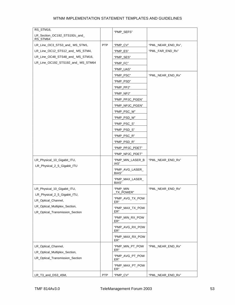
MTNM IMPLEMENTATION STATEMENT TEMPLATES AND GUIDELINES
TMF 814Av3.0 TeleManagement Forum 2003 53
RS_STM16,
LR_Section_OC192_STS192c_and_ RS_STM64
“PMP_SEFS”
“PMP_CV”
“PMP_ES”
“PMP_SES”
“PMP_FC”
“PMP_UAS”
“PML_NEAR_END_Rx”,
“PML_FAR_END_Rx”
“PMP_PSC”
“PMP_PSD”
“PMP_PPJ”
“PMP_NPJ”
“PMP_PPJC_PGEN”
“PMP_NPJC_PGEN”
“PMP_PSC_W”
“PMP_PSD_W”
“PMP_PSC_S”
“PMP_PSD_S”
“PMP_PSC_R”
“PMP_PSD_R”
“PMP_PPJC_PDET”
LR_Line_OC3_STS3_and_ MS_STM1,
LR_Line_OC12_STS12_and_ MS_STM4,
LR_Line_OC48_STS48_and_ MS_STM16,
LR_Line_OC192_STS192_and_ MS_STM64
PTP
“PMP_NPJC_PDET”
“PML_NEAR_END_Rx”
“PMP_MIN_LASER_BIAS”
“PMP_AVG_LASER_BIAS”
LR_Physical_10_Gigabit_ITU,
LR_Physical_2_5_Gigabit_ITU
“PMP_MAX_LASER_BIAS”
“PML_NEAR_END_Rx”
“PMP_MIN _TX_POWER”
“PMP_AVG_TX_POWER”
“PMP_MAX_TX_POWER”
“PMP_MIN_RX_POWER”
“PMP_AVG_RX_POWER”
LR_Physical_10_Gigabit_ITU,
LR_Physical_2_5_Gigabit_ITU,
LR_Optical_Channel,
LR_Optical_Multiplex_Section,
LR_Optical_Transmission_Section
“PMP_MAX_RX_POWER”
“PML_NEAR_END_Rx”
“PMP_MIN_PT_POWER”
“PMP_AVG_PT_POWER”
LR_Optical_Channel,
LR_Optical_Multiplex_Section,
LR_Optical_Transmission_Section
“PMP_MAX_PT_POWER”
“PML_NEAR_END_Rx”
LR_T3_and_DS3_45M, PTP “PMP_CV” “PML_NEAR_END_Rx”
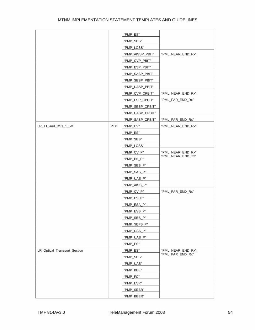
MTNM IMPLEMENTATION STATEMENT TEMPLATES AND GUIDELINES
TMF 814Av3.0 TeleManagement Forum 2003 54
“PMP_ES”
“PMP_SES”
“PMP_LOSS”
“PMP_AISSP_PBIT”
“PMP_CVP_PBIT”
“PMP_ESP_PBIT”
“PMP_SASP_PBIT”
“PMP_SESP_PBIT”
“PMP_UASP_PBIT”
“PML_NEAR_END_Rx”,
“PMP_CVP_CPBIT”
“PMP_ESP_CPBIT”
“PMP_SESP_CPBIT”
“PMP_UASP_CPBIT”
“PML_NEAR_END_Rx”,
“PML_FAR_END_Rx”
“PMP_SASP_CPBIT” “PML_FAR_END_Rx”
“PMP_CV”
“PMP_ES”
“PMP_SES”
“PMP_LOSS”
“PML_NEAR_END_Rx”
“PMP_CV_P”
“PMP_ES_P”
“PMP_SES_P”
“PMP_SAS_P”
“PMP_UAS_P”
“PMP_AISS_P”
“PML_NEAR_END_Rx” “PML_NEAR_END_Tx”
“PMP_CV_P”
“PMP_ES_P”
“PMP_ESA_P”
“PMP_ESB_P”
“PMP_SES_P”
“PMP_SEFS_P”
“PMP_CSS_P”
“PMP_UAS_P”
LR_T1_and_DS1_1_5M PTP
“PMP_ES”
“PML_FAR_END_Rx”
“PMP_ES”
“PMP_SES”
“PMP_UAS”
“PMP_BBE”
“PMP_FC”
“PMP_ESR”
“PMP_SESR”
LR_Optical_Transport_Section
“PMP_BBER”
“PML_NEAR_END_Rx”, “PML_FAR_END_Rx”
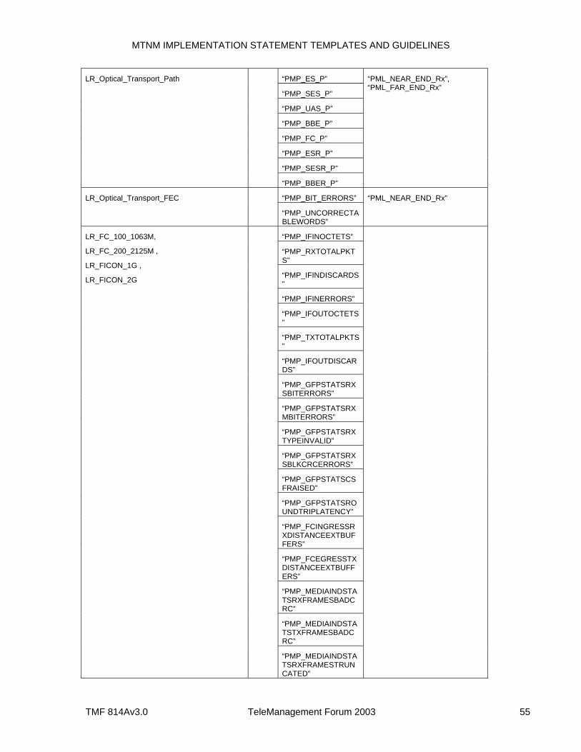
MTNM IMPLEMENTATION STATEMENT TEMPLATES AND GUIDELINES
TMF 814Av3.0 TeleManagement Forum 2003 55
“PMP_ES_P”
“PMP_SES_P”
“PMP_UAS_P”
“PMP_BBE_P”
“PMP_FC_P”
“PMP_ESR_P”
“PMP_SESR_P”
LR_Optical_Transport_Path
“PMP_BBER_P”
“PML_NEAR_END_Rx”, “PML_FAR_END_Rx”
“PMP_BIT_ERRORS” LR_Optical_Transport_FEC
“PMP_UNCORRECTABLEWORDS”
“PML_NEAR_END_Rx”
“PMP_IFINOCTETS”
“PMP_RXTOTALPKTS”
“PMP_IFINDISCARDS”
“PMP_IFINERRORS”
“PMP_IFOUTOCTETS”
“PMP_TXTOTALPKTS”
“PMP_IFOUTDISCARDS”
“PMP_GFPSTATSRXSBITERRORS”
“PMP_GFPSTATSRXMBITERRORS”
“PMP_GFPSTATSRXTYPEINVALID”
“PMP_GFPSTATSRXSBLKCRCERRORS”
“PMP_GFPSTATSCSFRAISED”
“PMP_GFPSTATSROUNDTRIPLATENCY”
“PMP_FCINGRESSRXDISTANCEEXTBUFFERS”
“PMP_FCEGRESSTXDISTANCEEXTBUFFERS”
“PMP_MEDIAINDSTATSRXFRAMESBADCRC”
“PMP_MEDIAINDSTATSTXFRAMESBADCRC”
LR_FC_100_1063M,
LR_FC_200_2125M ,
LR_FICON_1G ,
LR_FICON_2G
“PMP_MEDIAINDSTATSRXFRAMESTRUNCATED”
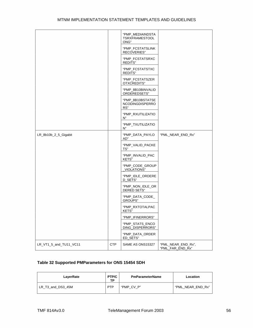
MTNM IMPLEMENTATION STATEMENT TEMPLATES AND GUIDELINES
TMF 814Av3.0 TeleManagement Forum 2003 56
“PMP_MEDIAINDSTATSRXFRAMESTOOLONG”
“PMP_FCSTATSLINKRECOVERIES”
“PMP_FCSTATSRXCREDITS”
“PMP_FCSTATSTXCREDITS”
“PMP_FCSTATSZEROTXCREDITS”
“PMP_8B10BINVALIDORDEREDSETS”
“PMP_8B10BSTATSENCODINGDISPERRORS”
“PMP_RXUTILIZATION”
“PMP_TXUTILIZATION”
“PMP_DATA_PAYLOAD”
“PMP_VALID_PACKETS”
“PMP_INVALID_PACKETS”
“PMP_CODE_GROUP_VIOLATIONS”
“PMP_IDLE_ORDERED_SETS”
“PMP_NON_IDLE_ORDERED SETS”
“PMP_DATA_CODE_GROUPS”
“PMP_RXTOTALPACKETS”
“PMP_IFINERRORS”
“PMP_STATS_ENCODING_DISPERRORS”
LR_8b10b_2_5_Gigabit
“PMP_DATA_ORDERED_SETS”
“PML_NEAR_END_Rx”
LR_VT1_5_and_TU11_VC11 CTP SAME AS ONS15327 “PML_NEAR_END_Rx”, “PML_FAR_END_Rx”
Table 32 Supported PMParameters for ONS 15454 SDH
LayerRate PTP/C
TP PmParameterName Location
LR_T3_and_DS3_45M PTP “PMP_CV_P” “PML_NEAR_END_Rx”
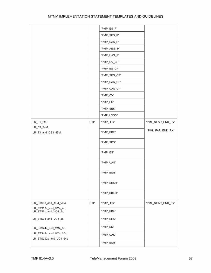
MTNM IMPLEMENTATION STATEMENT TEMPLATES AND GUIDELINES
TMF 814Av3.0 TeleManagement Forum 2003 57
“PMP_ES_P”
“PMP_SES_P”
“PMP_SAS_P”
“PMP_AISS_P”
“PMP_UAS_P”
“PMP_CV_CP”
“PMP_ES_CP”
“PMP_SES_CP”
“PMP_SAS_CP”
“PMP_UAS_CP”
“PMP_CV”
“PMP_ES”
“PMP_SES”
“PMP_LOSS”
“PMP_ EB”
“PMP_BBE”
“PMP_SES”
“PMP_ES”
“PMP_UAS”
“PMP_ESR”
“PMP_SESR”
LR_E1_2M,
LR_E3_34M,
LR_T3_and_DS3_45M,
CTP
“PMP_BBER”
“PML_NEAR_END_Rx” ,
“PML_FAR_END_RX”
“PMP_ EB”
“PMP_BBE”
“PMP_SES”
“PMP_ES”
“PMP_UAS”
LR_STS3c_and_AU4_VC4,
LR_STS12c_and_VC4_4c, LR_STS6c_and_VC4_2c,
LR_STS9c_and_VC4_3c,
LR_STS24c_and_VC4_8c,
LR_STS48c_and_VC4_16c,
LR_STS192c_and_VC4_64c
CTP
“PMP_ESR”
“PML_NEAR_END_Rx”
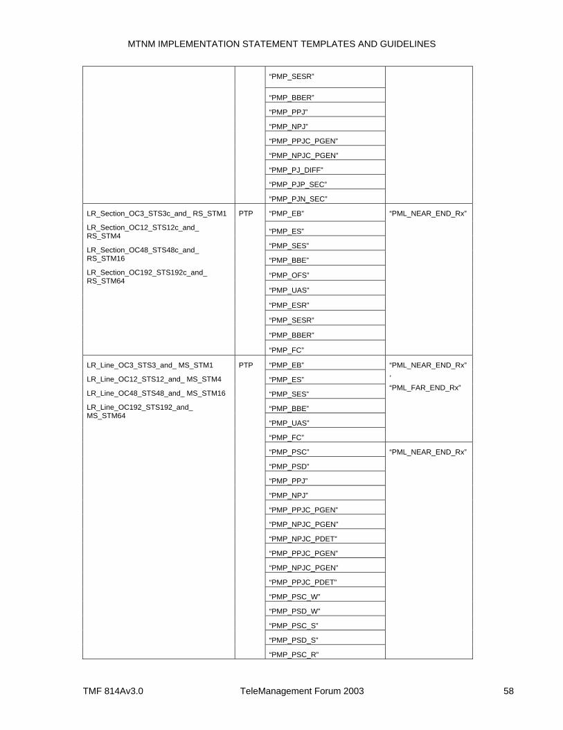
MTNM IMPLEMENTATION STATEMENT TEMPLATES AND GUIDELINES
TMF 814Av3.0 TeleManagement Forum 2003 58
“PMP_SESR”
“PMP_BBER”
“PMP_PPJ”
“PMP_NPJ”
“PMP_PPJC_PGEN”
“PMP_NPJC_PGEN”
“PMP_PJ_DIFF”
“PMP_PJP_SEC”
“PMP_PJN_SEC”
“PMP_EB”
“PMP_ES”
“PMP_SES”
“PMP_BBE”
“PMP_OFS”
“PMP_UAS”
“PMP_ESR”
“PMP_SESR”
“PMP_BBER”
LR_Section_OC3_STS3c_and_ RS_STM1
LR_Section_OC12_STS12c_and_ RS_STM4
LR_Section_OC48_STS48c_and_ RS_STM16
LR_Section_OC192_STS192c_and_ RS_STM64
PTP
“PMP_FC”
“PML_NEAR_END_Rx”
“PMP_EB”
“PMP_ES”
“PMP_SES”
“PMP_BBE”
“PMP_UAS”
“PMP_FC”
“PML_NEAR_END_Rx”,
“PML_FAR_END_Rx”
“PMP_PSC”
“PMP_PSD”
“PMP_PPJ”
“PMP_NPJ”
“PMP_PPJC_PGEN”
“PMP_NPJC_PGEN”
“PMP_NPJC_PDET”
“PMP_PPJC_PGEN”
“PMP_NPJC_PGEN”
“PMP_PPJC_PDET”
“PMP_PSC_W”
“PMP_PSD_W”
“PMP_PSC_S”
“PMP_PSD_S”
LR_Line_OC3_STS3_and_ MS_STM1
LR_Line_OC12_STS12_and_ MS_STM4
LR_Line_OC48_STS48_and_ MS_STM16
LR_Line_OC192_STS192_and_ MS_STM64
PTP
“PMP_PSC_R”
“PML_NEAR_END_Rx”
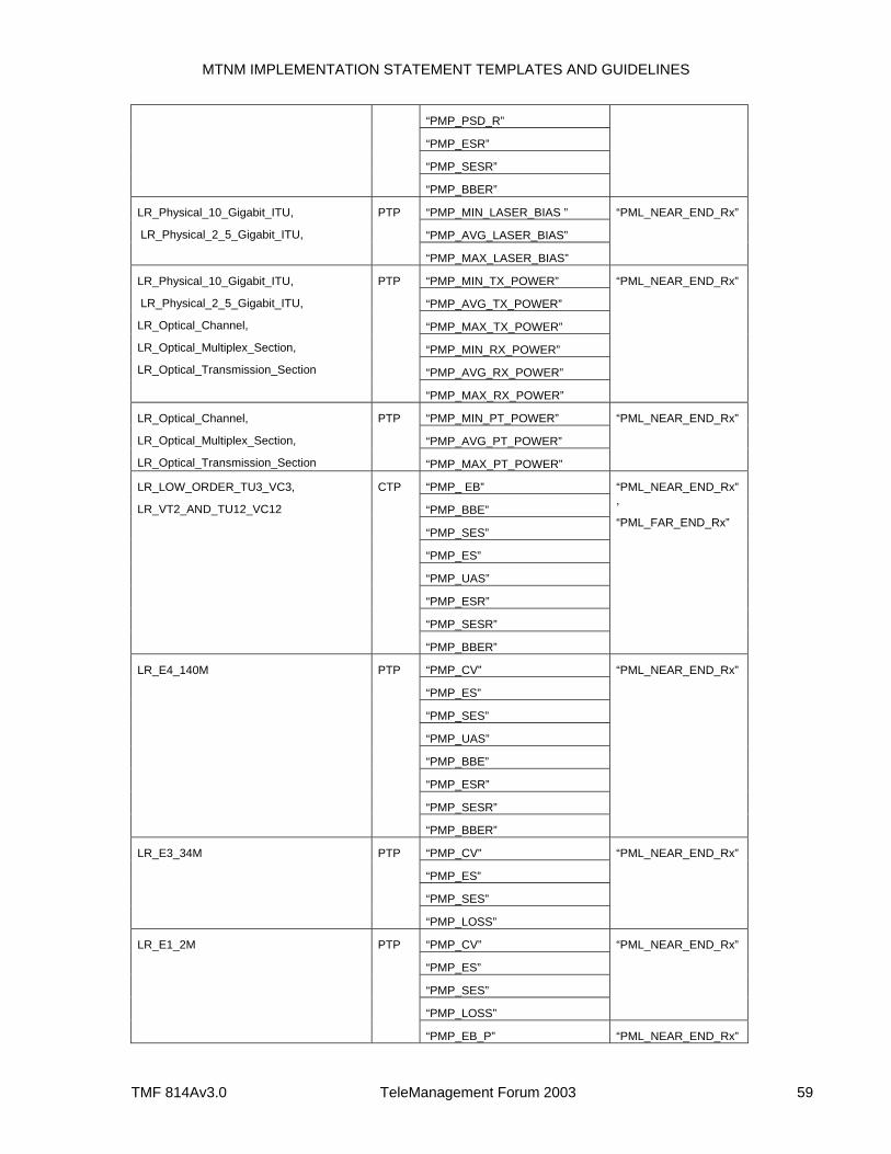
MTNM IMPLEMENTATION STATEMENT TEMPLATES AND GUIDELINES
TMF 814Av3.0 TeleManagement Forum 2003 59
“PMP_PSD_R”
“PMP_ESR”
“PMP_SESR”
“PMP_BBER”
“PMP_MIN_LASER_BIAS ”
“PMP_AVG_LASER_BIAS”
LR_Physical_10_Gigabit_ITU,
LR_Physical_2_5_Gigabit_ITU,
PTP
“PMP_MAX_LASER_BIAS”
“PML_NEAR_END_Rx”
“PMP_MIN_TX_POWER”
“PMP_AVG_TX_POWER”
“PMP_MAX_TX_POWER”
“PMP_MIN_RX_POWER”
“PMP_AVG_RX_POWER”
LR_Physical_10_Gigabit_ITU,
LR_Physical_2_5_Gigabit_ITU,
LR_Optical_Channel,
LR_Optical_Multiplex_Section,
LR_Optical_Transmission_Section
PTP
“PMP_MAX_RX_POWER”
“PML_NEAR_END_Rx”
“PMP_MIN_PT_POWER”
“PMP_AVG_PT_POWER”
LR_Optical_Channel,
LR_Optical_Multiplex_Section,
LR_Optical_Transmission_Section
PTP
“PMP_MAX_PT_POWER”
“PML_NEAR_END_Rx”
“PMP_ EB”
“PMP_BBE”
“PMP_SES”
“PMP_ES”
“PMP_UAS”
“PMP_ESR”
“PMP_SESR”
LR_LOW_ORDER_TU3_VC3,
LR_VT2_AND_TU12_VC12
CTP
“PMP_BBER”
“PML_NEAR_END_Rx”,
“PML_FAR_END_Rx”
“PMP_CV”
“PMP_ES”
“PMP_SES”
“PMP_UAS”
“PMP_BBE”
“PMP_ESR”
“PMP_SESR”
LR_E4_140M PTP
“PMP_BBER”
“PML_NEAR_END_Rx”
“PMP_CV”
“PMP_ES”
“PMP_SES”
LR_E3_34M PTP
“PMP_LOSS”
“PML_NEAR_END_Rx”
“PMP_CV”
“PMP_ES”
“PMP_SES”
“PMP_LOSS”
“PML_NEAR_END_Rx” LR_E1_2M PTP
“PMP_EB_P” “PML_NEAR_END_Rx”
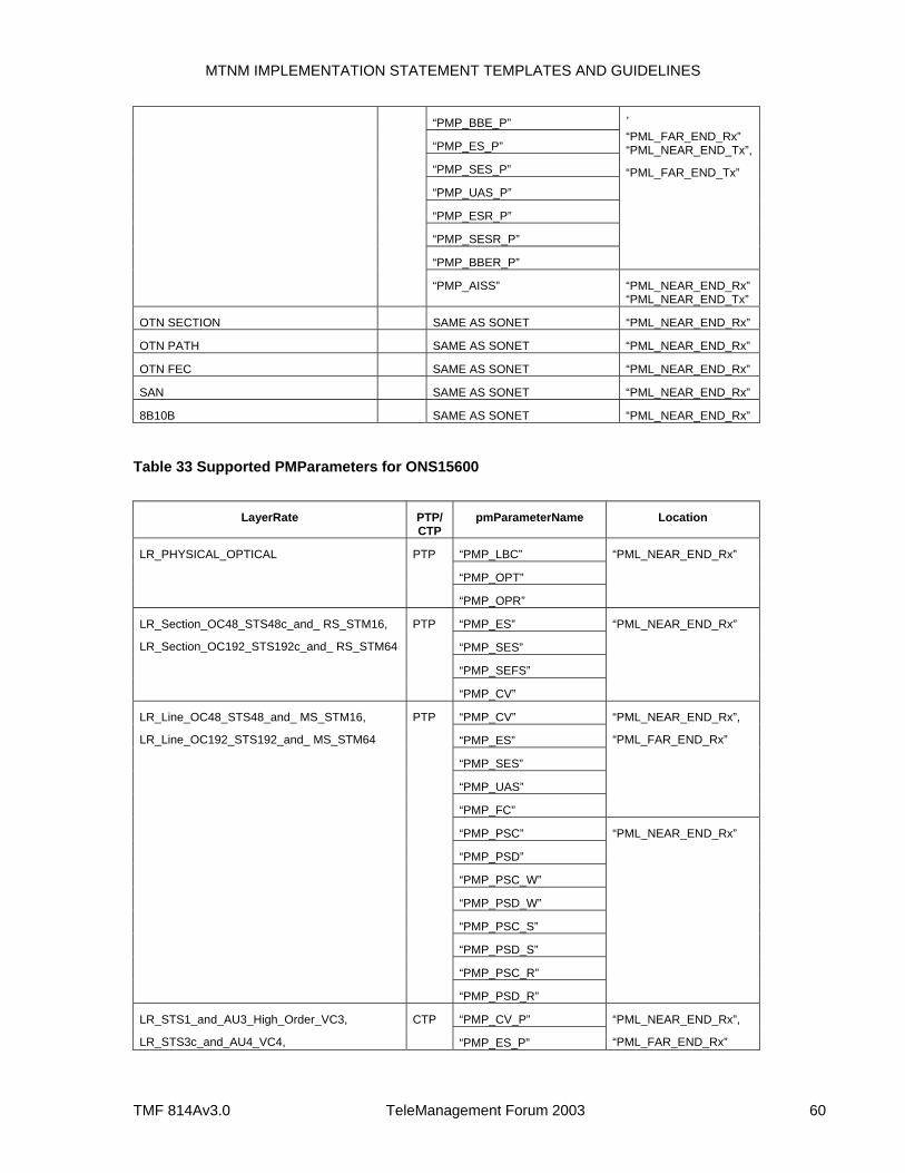
MTNM IMPLEMENTATION STATEMENT TEMPLATES AND GUIDELINES
TMF 814Av3.0 TeleManagement Forum 2003 60
“PMP_BBE_P”
“PMP_ES_P”
“PMP_SES_P”
“PMP_UAS_P”
“PMP_ESR_P”
“PMP_SESR_P”
“PMP_BBER_P”
,
“PML_FAR_END_Rx” “PML_NEAR_END_Tx”,
“PML_FAR_END_Tx”
“PMP_AISS” “PML_NEAR_END_Rx” “PML_NEAR_END_Tx”
OTN SECTION SAME AS SONET “PML_NEAR_END_Rx”
OTN PATH SAME AS SONET “PML_NEAR_END_Rx”
OTN FEC SAME AS SONET “PML_NEAR_END_Rx”
SAN SAME AS SONET “PML_NEAR_END_Rx”
8B10B SAME AS SONET “PML_NEAR_END_Rx”
Table 33 Supported PMParameters for ONS15600
LayerRate PTP/
CTP pmParameterName Location
“PMP_LBC”
“PMP_OPT”
LR_PHYSICAL_OPTICAL PTP
“PMP_OPR”
“PML_NEAR_END_Rx”
“PMP_ES”
“PMP_SES”
“PMP_SEFS”
LR_Section_OC48_STS48c_and_ RS_STM16,
LR_Section_OC192_STS192c_and_ RS_STM64
PTP
“PMP_CV”
“PML_NEAR_END_Rx”
“PMP_CV”
“PMP_ES”
“PMP_SES”
“PMP_UAS”
“PMP_FC”
“PML_NEAR_END_Rx”,
“PML_FAR_END_Rx”
“PMP_PSC”
“PMP_PSD”
“PMP_PSC_W”
“PMP_PSD_W”
“PMP_PSC_S”
“PMP_PSD_S”
“PMP_PSC_R”
LR_Line_OC48_STS48_and_ MS_STM16,
LR_Line_OC192_STS192_and_ MS_STM64
PTP
“PMP_PSD_R”
“PML_NEAR_END_Rx”
“PMP_CV_P” LR_STS1_and_AU3_High_Order_VC3,
LR_STS3c_and_AU4_VC4,
CTP
“PMP_ES_P”
“PML_NEAR_END_Rx”,
“PML_FAR_END_Rx”
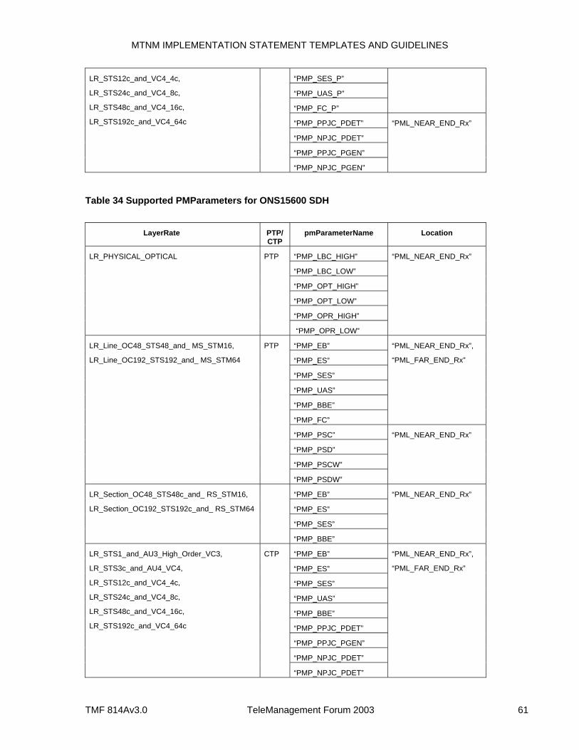
MTNM IMPLEMENTATION STATEMENT TEMPLATES AND GUIDELINES
TMF 814Av3.0 TeleManagement Forum 2003 61
“PMP_SES_P”
“PMP_UAS_P”
“PMP_FC_P”
“PMP_PPJC_PDET”
“PMP_NPJC_PDET”
“PMP_PPJC_PGEN”
LR_STS12c_and_VC4_4c,
LR_STS24c_and_VC4_8c,
LR_STS48c_and_VC4_16c,
LR_STS192c_and_VC4_64c
“PMP_NPJC_PGEN”
“PML_NEAR_END_Rx”
Table 34 Supported PMParameters for ONS15600 SDH
LayerRate PTP/
CTP pmParameterName Location
“PMP_LBC_HIGH”
“PMP_LBC_LOW”
“PMP_OPT_HIGH”
“PMP_OPT_LOW”
“PMP_OPR_HIGH”
LR_PHYSICAL_OPTICAL PTP
“PMP_OPR_LOW”
“PML_NEAR_END_Rx”
“PMP_EB”
“PMP_ES”
“PMP_SES”
“PMP_UAS”
“PMP_BBE”
“PMP_FC”
“PML_NEAR_END_Rx”,
“PML_FAR_END_Rx”
“PMP_PSC”
“PMP_PSD”
“PMP_PSCW”
LR_Line_OC48_STS48_and_ MS_STM16,
LR_Line_OC192_STS192_and_ MS_STM64
PTP
“PMP_PSDW”
“PML_NEAR_END_Rx”
“PMP_EB”
“PMP_ES”
“PMP_SES”
LR_Section_OC48_STS48c_and_ RS_STM16,
LR_Section_OC192_STS192c_and_ RS_STM64
“PMP_BBE”
“PML_NEAR_END_Rx”
“PMP_EB”
“PMP_ES”
“PMP_SES”
“PMP_UAS”
“PMP_BBE”
“PMP_PPJC_PDET”
“PMP_PPJC_PGEN”
“PMP_NPJC_PDET”
LR_STS1_and_AU3_High_Order_VC3,
LR_STS3c_and_AU4_VC4,
LR_STS12c_and_VC4_4c,
LR_STS24c_and_VC4_8c,
LR_STS48c_and_VC4_16c,
LR_STS192c_and_VC4_64c
CTP
“PMP_NPJC_PDET”
“PML_NEAR_END_Rx”,
“PML_FAR_END_Rx”
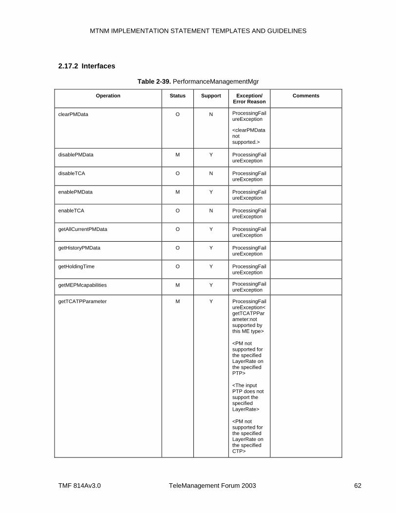
MTNM IMPLEMENTATION STATEMENT TEMPLATES AND GUIDELINES
TMF 814Av3.0 TeleManagement Forum 2003 62
2.17.2 Interfaces
Table 2-39. PerformanceManagementMgr
Operation Status Support Exception/ Error Reason
Comments
clearPMData O N ProcessingFailureException
<clearPMData not supported.>
disablePMData M Y ProcessingFailureException
disableTCA O N ProcessingFailureException
enablePMData M Y ProcessingFailureException
enableTCA O N ProcessingFailureException
getAllCurrentPMData O Y ProcessingFailureException
getHistoryPMData O Y ProcessingFailureException
getHoldingTime O Y ProcessingFailureException
getMEPMcapabilities M Y ProcessingFailureException
getTCATPParameter M Y ProcessingFailureException<getTCATPParameter:not supported by this ME type>
<PM not supported for the specified LayerRate on the specified PTP>
<The input PTP does not support the specified LayerRate>
<PM not supported for the specified LayerRate on the specified CTP>
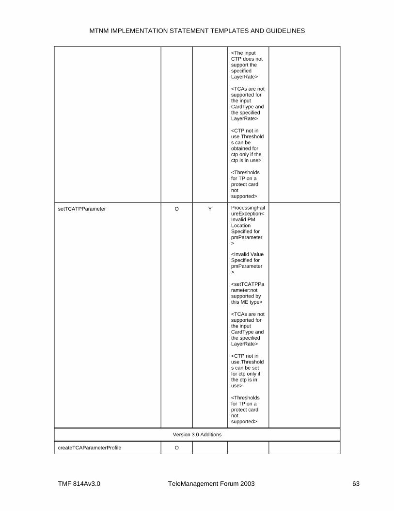
MTNM IMPLEMENTATION STATEMENT TEMPLATES AND GUIDELINES
TMF 814Av3.0 TeleManagement Forum 2003 63
<The input CTP does not support the specified LayerRate>
<TCAs are not supported for the input CardType and the specified LayerRate>
<CTP not in use.Thresholds can be obtained for ctp only if the ctp is in use>
<Thresholds for TP on a protect card not supported>
setTCATPParameter O Y ProcessingFailureException<Invalid PM Location Specified for pmParameter>
<Invalid Value Specified for pmParameter>
<setTCATPParameter:not supported by this ME type>
<TCAs are not supported for the input CardType and the specified LayerRate>
<CTP not in use.Thresholds can be set for ctp only if the ctp is in use>
<Thresholds for TP on a protect card not supported>
Version 3.0 Additions
createTCAParameterProfile O
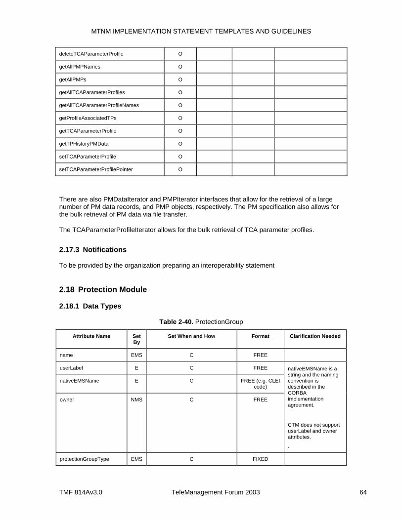
MTNM IMPLEMENTATION STATEMENT TEMPLATES AND GUIDELINES
TMF 814Av3.0 TeleManagement Forum 2003 64
deleteTCAParameterProfile O
getAllPMPNames O
getAllPMPs O
getAllTCAParameterProfiles O
getAllTCAParameterProfileNames O
getProfileAssociatedTPs O
getTCAParameterProfile O
getTPHistoryPMData O
setTCAParameterProfile O
setTCAParameterProfilePointer O
There are also PMDataIterator and PMPIterator interfaces that allow for the retrieval of a large number of PM data records, and PMP objects, respectively. The PM specification also allows for the bulk retrieval of PM data via file transfer.
The TCAParameterProfileIterator allows for the bulk retrieval of TCA parameter profiles.
2.17.3 Notifications
To be provided by the organization preparing an interoperability statement
2.18 Protection Module
2.18.1 Data Types
Table 2-40. ProtectionGroup
Attribute Name Set By
Set When and How Format Clarification Needed
name EMS C FREE
userLabel E C FREE
nativeEMSName E C FREE (e.g. CLEI code)
owner NMS C FREE
nativeEMSName is a string and the naming convention is described in the CORBA implementation agreement.
CTM does not support userLabel and owner attributes.
.
protectionGroupType EMS C FIXED
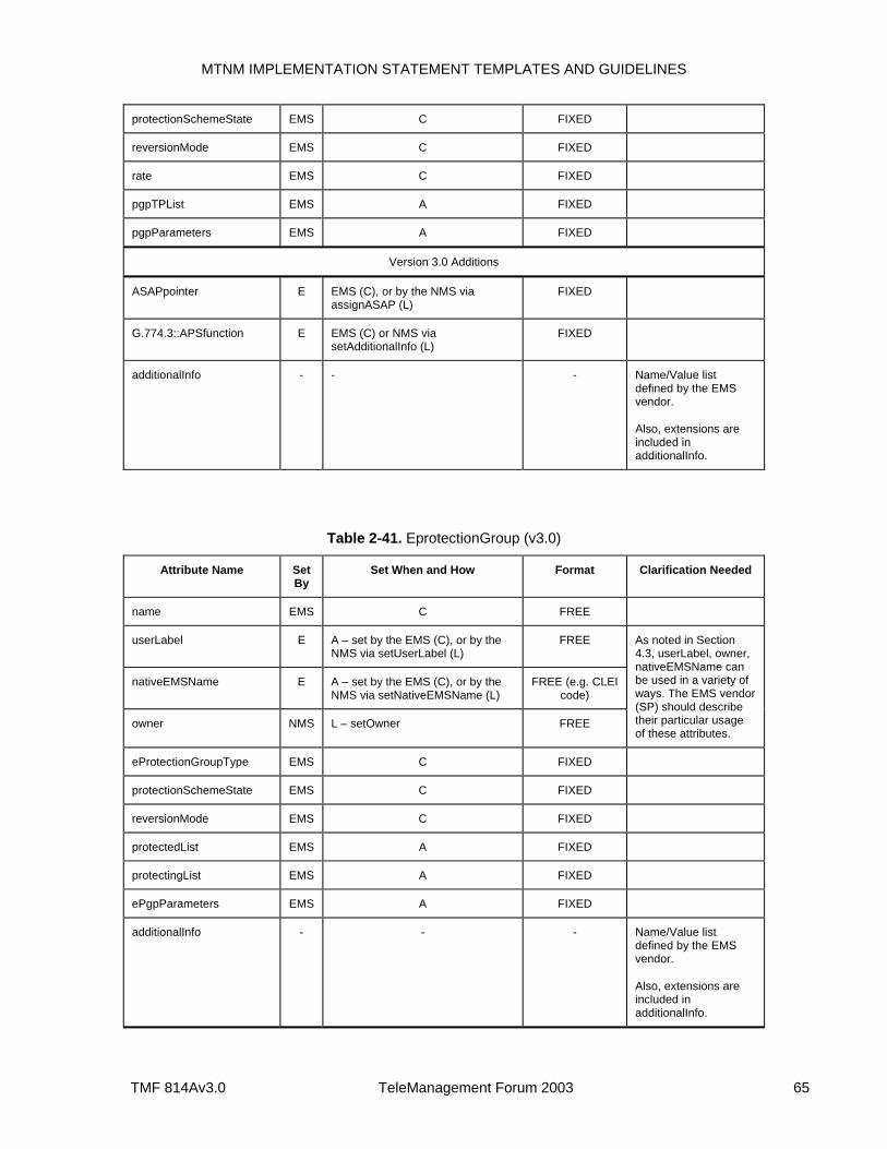
MTNM IMPLEMENTATION STATEMENT TEMPLATES AND GUIDELINES
TMF 814Av3.0 TeleManagement Forum 2003 65
protectionSchemeState EMS C FIXED
reversionMode EMS C FIXED
rate EMS C FIXED
pgpTPList EMS A FIXED
pgpParameters EMS A FIXED
Version 3.0 Additions
ASAPpointer E EMS (C), or by the NMS via assignASAP (L)
FIXED
G.774.3::APSfunction E EMS (C) or NMS via setAdditionalInfo (L)
FIXED
additionalInfo - - - Name/Value list defined by the EMS vendor.
Also, extensions are included in additionalInfo.
Table 2-41. EprotectionGroup (v3.0)
Attribute Name Set By
Set When and How Format Clarification Needed
name EMS C FREE
userLabel E A – set by the EMS (C), or by the NMS via setUserLabel (L)
FREE
nativeEMSName E A – set by the EMS (C), or by the NMS via setNativeEMSName (L)
FREE (e.g. CLEI code)
owner NMS L – setOwner FREE
As noted in Section 4.3, userLabel, owner, nativeEMSName can be used in a variety of ways. The EMS vendor (SP) should describe their particular usage of these attributes.
eProtectionGroupType EMS C FIXED
protectionSchemeState EMS C FIXED
reversionMode EMS C FIXED
protectedList EMS A FIXED
protectingList EMS A FIXED
ePgpParameters EMS A FIXED
additionalInfo - - - Name/Value list defined by the EMS vendor.
Also, extensions are included in additionalInfo.
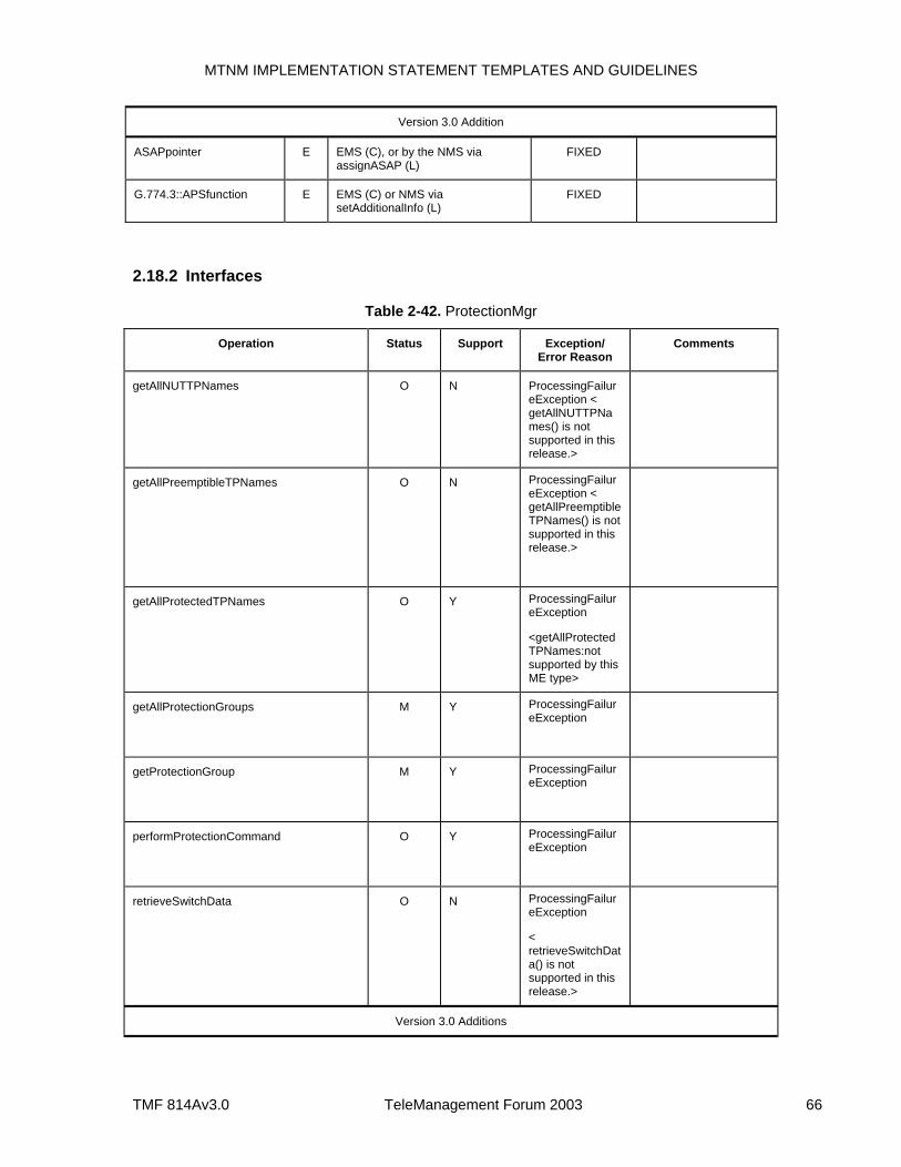
MTNM IMPLEMENTATION STATEMENT TEMPLATES AND GUIDELINES
TMF 814Av3.0 TeleManagement Forum 2003 66
Version 3.0 Addition
ASAPpointer E EMS (C), or by the NMS via assignASAP (L)
FIXED
G.774.3::APSfunction E EMS (C) or NMS via setAdditionalInfo (L)
FIXED
2.18.2 Interfaces
Table 2-42. ProtectionMgr
Operation Status Support Exception/ Error Reason
Comments
getAllNUTTPNames O N ProcessingFailureException < getAllNUTTPNames() is not supported in this release.>
getAllPreemptibleTPNames O N ProcessingFailureException < getAllPreemptibleTPNames() is not supported in this release.>
getAllProtectedTPNames O Y ProcessingFailureException
<getAllProtectedTPNames:not supported by this ME type>
getAllProtectionGroups M Y ProcessingFailureException
getProtectionGroup M Y ProcessingFailureException
performProtectionCommand O Y ProcessingFailureException
retrieveSwitchData O N ProcessingFailureException
< retrieveSwitchData() is not supported in this release.>
Version 3.0 Additions
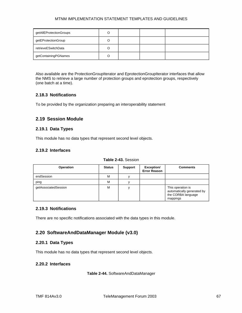
MTNM IMPLEMENTATION STATEMENT TEMPLATES AND GUIDELINES
TMF 814Av3.0 TeleManagement Forum 2003 67
getAllEProtectionGroups O
getEProtectionGroup O
retrieveESwitchData O
getContainingPGNames O
Also available are the ProtectionGroupIterator and EprotectionGroupIterator interfaces that allow the NMS to retrieve a large number of protection groups and eprotection groups, respectively (one batch at a time).
2.18.3 Notifications
To be provided by the organization preparing an interoperability statement
2.19 Session Module
2.19.1 Data Types
This module has no data types that represent second level objects.
2.19.2 Interfaces
Table 2-43. Session
Operation Status Support Exception/ Error Reason
Comments
endSession M y
ping M y
getAssociatedSession M y This operation is automatically generated by the CORBA language mappings
2.19.3 Notifications
There are no specific notifications associated with the data types in this module.
2.20 SoftwareAndDataManager Module (v3.0)
2.20.1 Data Types
This module has no data types that represent second level objects.
2.20.2 Interfaces
Table 2-44. SoftwareAndDataManager
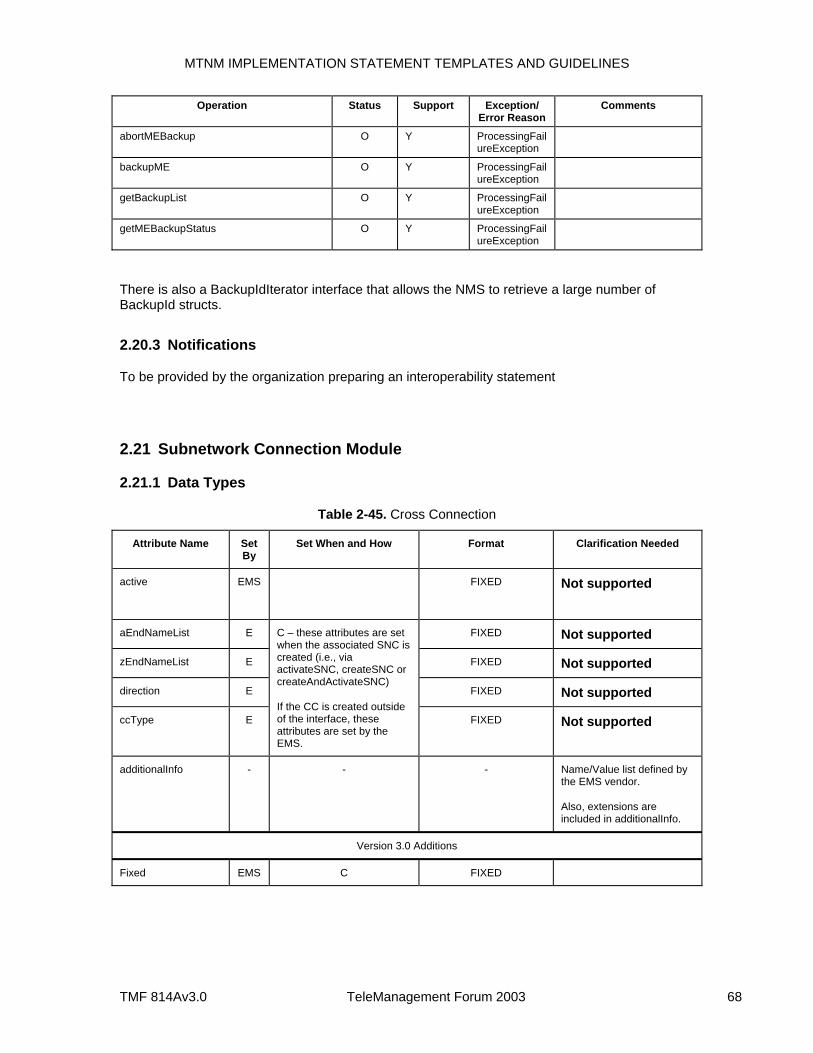
MTNM IMPLEMENTATION STATEMENT TEMPLATES AND GUIDELINES
TMF 814Av3.0 TeleManagement Forum 2003 68
Operation Status Support Exception/ Error Reason
Comments
abortMEBackup O Y ProcessingFailureException
backupME O Y ProcessingFailureException
getBackupList O Y ProcessingFailureException
getMEBackupStatus O Y ProcessingFailureException
There is also a BackupIdIterator interface that allows the NMS to retrieve a large number of BackupId structs.
2.20.3 Notifications
To be provided by the organization preparing an interoperability statement
2.21 Subnetwork Connection Module
2.21.1 Data Types
Table 2-45. Cross Connection
Attribute Name Set By
Set When and How Format Clarification Needed
active EMS
FIXED Not supported
aEndNameList E FIXED Not supported
zEndNameList E FIXED Not supported
direction E FIXED Not supported
ccType E
C – these attributes are set when the associated SNC is created (i.e., via activateSNC, createSNC or createAndActivateSNC)
If the CC is created outside of the interface, these attributes are set by the EMS.
FIXED Not supported
additionalInfo - - - Name/Value list defined by the EMS vendor.
Also, extensions are included in additionalInfo.
Version 3.0 Additions
Fixed EMS C FIXED
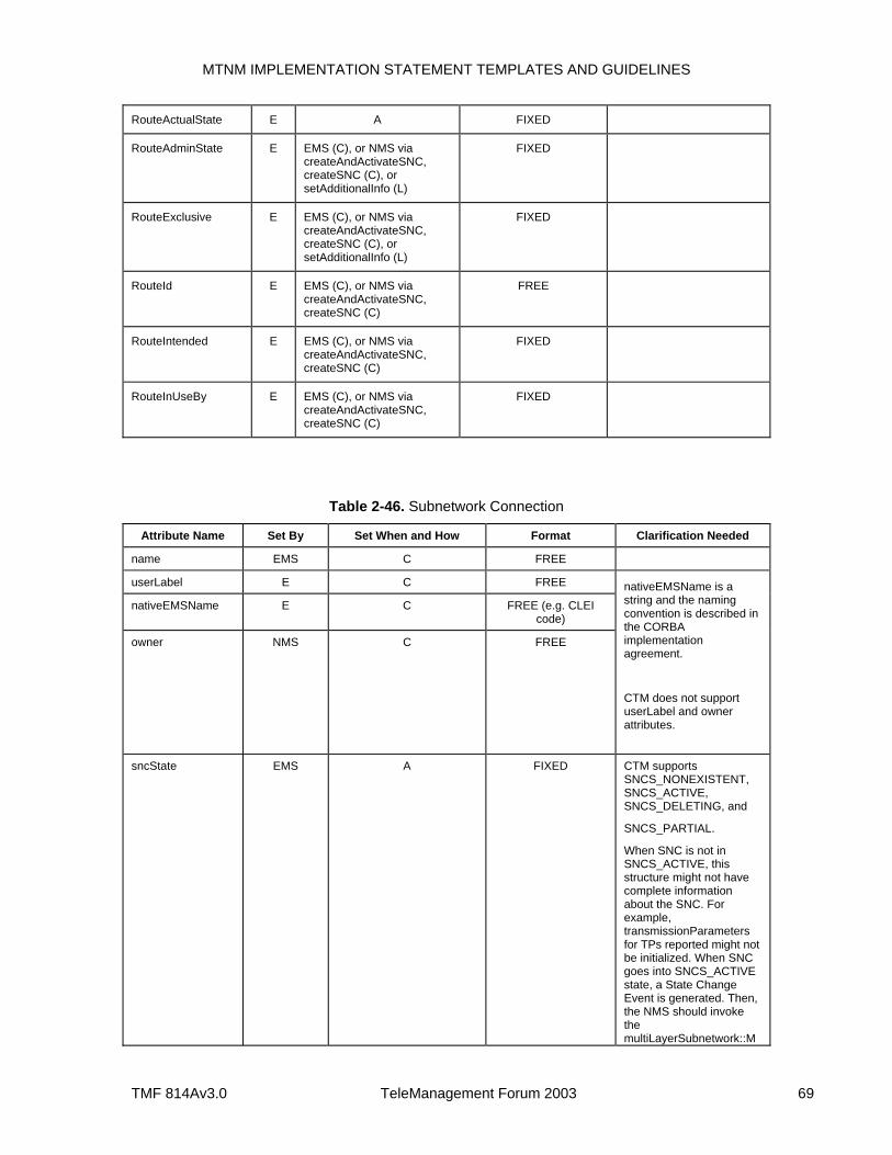
MTNM IMPLEMENTATION STATEMENT TEMPLATES AND GUIDELINES
TMF 814Av3.0 TeleManagement Forum 2003 69
RouteActualState E A FIXED
RouteAdminState E EMS (C), or NMS via createAndActivateSNC, createSNC (C), or setAdditionalInfo (L)
FIXED
RouteExclusive E EMS (C), or NMS via createAndActivateSNC, createSNC (C), or setAdditionalInfo (L)
FIXED
RouteId E EMS (C), or NMS via createAndActivateSNC, createSNC (C)
FREE
RouteIntended E EMS (C), or NMS via createAndActivateSNC, createSNC (C)
FIXED
RouteInUseBy E EMS (C), or NMS via createAndActivateSNC, createSNC (C)
FIXED
Table 2-46. Subnetwork Connection
Attribute Name Set By Set When and How Format Clarification Needed
name EMS C FREE
userLabel E C FREE
nativeEMSName E C FREE (e.g. CLEI code)
owner NMS C FREE
nativeEMSName is a string and the naming convention is described in the CORBA implementation agreement.
CTM does not support userLabel and owner attributes.
sncState EMS A FIXED CTM supports SNCS_NONEXISTENT, SNCS_ACTIVE, SNCS_DELETING, and
SNCS_PARTIAL.
When SNC is not in SNCS_ACTIVE, this structure might not have complete information about the SNC. For example, transmissionParameters for TPs reported might not be initialized. When SNC goes into SNCS_ACTIVE state, a State Change Event is generated. Then, the NMS should invoke the multiLayerSubnetwork::M
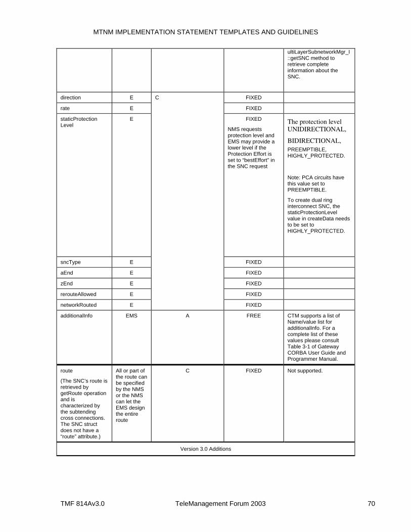
MTNM IMPLEMENTATION STATEMENT TEMPLATES AND GUIDELINES
TMF 814Av3.0 TeleManagement Forum 2003 70
ultiLayerSubnetworkMgr_I::getSNC method to retrieve complete information about the SNC.
direction E FIXED
rate E FIXED
staticProtection Level
E FIXED
NMS requests protection level and EMS may provide a lower level if the Protection Effort is set to “bestEffort” in the SNC request
The protection level UNIDIRECTIONAL,
BIDIRECTIONAL, PREEMPTIBLE, HIGHLY_PROTECTED.
Note: PCA circuits have this value set to PREEMPTIBLE.
To create dual ring interconnect SNC, the staticProtectionLevel value in createData needs to be set to HIGHLY_PROTECTED.
sncType E FIXED
aEnd E FIXED
zEnd E FIXED
rerouteAllowed E FIXED
networkRouted E
C
FIXED
additionalInfo EMS A FREE CTM supports a list of Name/value list for additionalInfo. For a complete list of these values please consult Table 3-1 of Gateway CORBA User Guide and Programmer Manual.
route
(The SNC’s route is retrieved by getRoute operation and is characterized by the subtending cross connections. The SNC struct does not have a “route” attribute.)
All or part of the route can be specified by the NMS or the NMS can let the EMS design the entire route
C FIXED Not supported.
Version 3.0 Additions
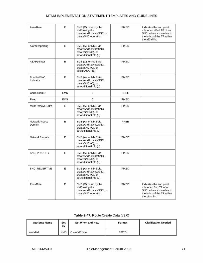
MTNM IMPLEMENTATION STATEMENT TEMPLATES AND GUIDELINES
TMF 814Av3.0 TeleManagement Forum 2003 71
A<n>Role E EMS (C) or set by the NMS using the createAndActivateSNC or createSNC operation
FIXED Indicates the end point role of an aEnd TP of an SNC, where <n> refers to the index of the TP within the aEnd list.
AlarmReporting E EMS (A), or NMS via createAndActivateSNC, createSNC (C), or setAdditionalInfo (L)
FIXED
ASAPpointer E EMS (C), or NMS via createAndActivateSNC, createSNC (C), or assignASAP (L)
FIXED
BundledSNC Indicator
E EMS (A), or NMS via createAndActivateSNC, createSNC (C), or setAdditionalInfo (L)
FIXED
CorrelationID EMS L FREE
Fixed EMS C FIXED
MustRemoveGTPs E EMS (A), or NMS via createAndActivateSNC, createSNC (C), or setAdditionalInfo (L)
FIXED
NetworkAccess Domain
E EMS (A), or NMS via createAndActivateSNC, createSNC (C), or setAdditionalInfo (L)
FREE
NetworkReroute E EMS (A), or NMS via createAndActivateSNC, createSNC (C), or setAdditionalInfo (L)
FIXED
SNC_PRIORITY E EMS (A), or NMS via createAndActivateSNC, createSNC (C), or setAdditionalInfo (L)
FIXED
SNC_REVERTIVE E EMS (A), or NMS via createAndActivateSNC, createSNC (C), or setAdditionalInfo (L)
FIXED
Z<n>Role E EMS (C) or set by the NMS using the createAndActivateSNC or createSNC operation
FIXED Indicates the end point role of a zEnd TP of an SNC, where <n> refers to the index of the TP within the zEnd list.
Table 2-47. Route Create Data (v3.0)
Attribute Name Set By
Set When and How Format Clarification Needed
intended NMS C – addRoute FIXED
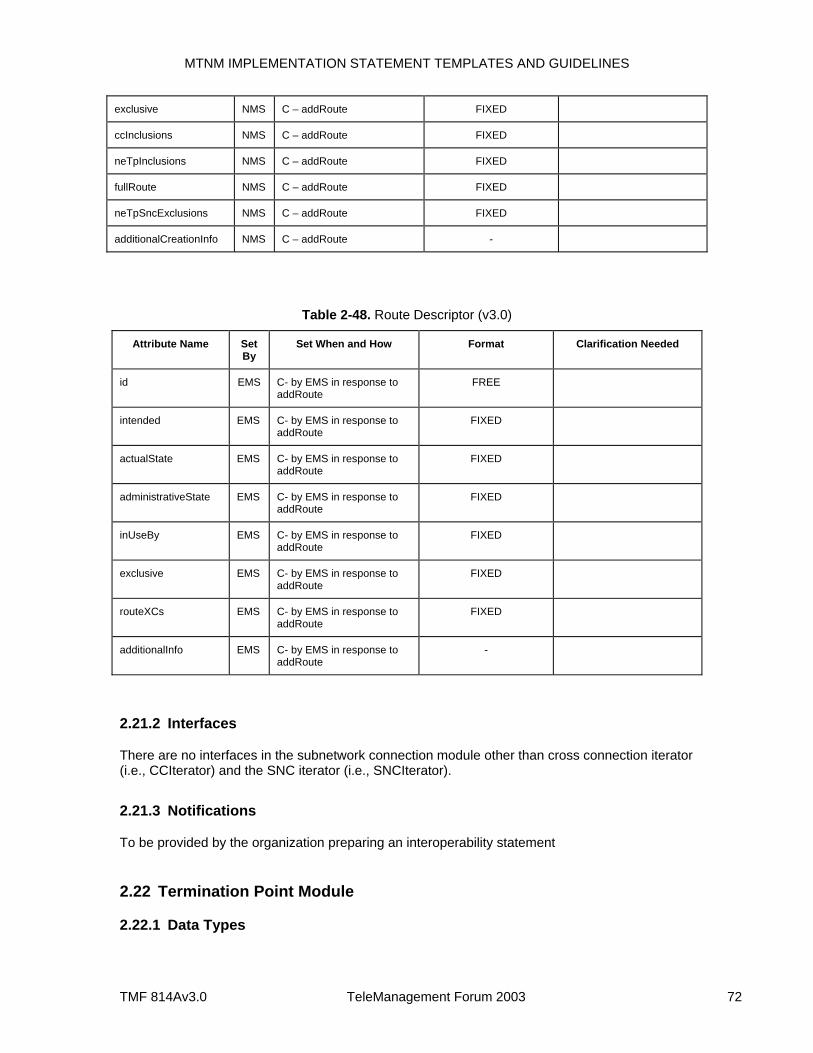
MTNM IMPLEMENTATION STATEMENT TEMPLATES AND GUIDELINES
TMF 814Av3.0 TeleManagement Forum 2003 72
exclusive NMS C – addRoute FIXED
ccInclusions NMS C – addRoute FIXED
neTpInclusions NMS C – addRoute FIXED
fullRoute NMS C – addRoute FIXED
neTpSncExclusions NMS C – addRoute FIXED
additionalCreationInfo NMS C – addRoute -
Table 2-48. Route Descriptor (v3.0)
Attribute Name Set By
Set When and How Format Clarification Needed
id EMS C- by EMS in response to addRoute
FREE
intended EMS C- by EMS in response to addRoute
FIXED
actualState EMS C- by EMS in response to addRoute
FIXED
administrativeState EMS C- by EMS in response to addRoute
FIXED
inUseBy EMS C- by EMS in response to addRoute
FIXED
exclusive EMS C- by EMS in response to addRoute
FIXED
routeXCs EMS C- by EMS in response to addRoute
FIXED
additionalInfo EMS C- by EMS in response to addRoute
-
2.21.2 Interfaces
There are no interfaces in the subnetwork connection module other than cross connection iterator (i.e., CCIterator) and the SNC iterator (i.e., SNCIterator).
2.21.3 Notifications
To be provided by the organization preparing an interoperability statement
2.22 Termination Point Module
2.22.1 Data Types
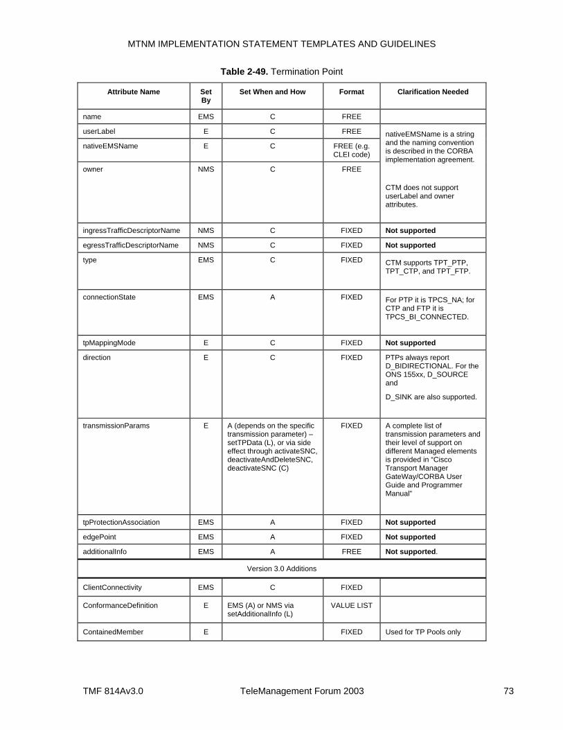
MTNM IMPLEMENTATION STATEMENT TEMPLATES AND GUIDELINES
TMF 814Av3.0 TeleManagement Forum 2003 73
Table 2-49. Termination Point
Attribute Name Set By
Set When and How Format Clarification Needed
name EMS C FREE
userLabel E C FREE
nativeEMSName E C FREE (e.g. CLEI code)
owner NMS C FREE
nativeEMSName is a string and the naming convention is described in the CORBA implementation agreement.
CTM does not support userLabel and owner attributes.
ingressTrafficDescriptorName NMS C FIXED Not supported
egressTrafficDescriptorName NMS C FIXED Not supported
type EMS C FIXED CTM supports TPT_PTP, TPT_CTP, and TPT_FTP.
connectionState EMS A FIXED For PTP it is TPCS_NA; for CTP and FTP it is TPCS_BI_CONNECTED.
tpMappingMode E C FIXED Not supported
direction E C FIXED PTPs always report D_BIDIRECTIONAL. For the ONS 155xx, D_SOURCE and
D_SINK are also supported.
transmissionParams E A (depends on the specific transmission parameter) –setTPData (L), or via side effect through activateSNC, deactivateAndDeleteSNC, deactivateSNC (C)
FIXED A complete list of transmission parameters and their level of support on different Managed elements is provided in “Cisco Transport Manager GateWay/CORBA User Guide and Programmer Manual”
tpProtectionAssociation EMS A FIXED Not supported
edgePoint EMS A FIXED Not supported
additionalInfo EMS A FREE Not supported.
Version 3.0 Additions
ClientConnectivity EMS C FIXED
ConformanceDefinition E EMS (A) or NMS via setAdditionalInfo (L)
VALUE LIST
ContainedMember E FIXED Used for TP Pools only

MTNM IMPLEMENTATION STATEMENT TEMPLATES AND GUIDELINES
TMF 814Av3.0 TeleManagement Forum 2003 74
DescriptionOfUser E EMS (A) or NMS via setAdditionalInfo (L)
FREE Used for TP Pools only
EgressTMDstate EMS A FIXED
EquipmentProtected EMS A FIXED
IngressTMDstate EMS A FIXED
MemberContainingME<n> E EMS (A) or NMS via modifyTPPool
FIXED Used for TP Pools only
MemberContainingTP<n> E EMS (A) or NMS via modifyTPPool
FIXED Used for TP Pools only
NetworkAccessDomain E EMS (C) or NMS via setAdditionalInfo (L)
FREE
NumberOfMembers E EMS (A) or NMS via modifyTPPool
FIXED Used for TP Pools only
NumberOfIdleMembers E EMS (A) or NMS via modifyTPPool
FIXED Used for TP Pools only
ServerConnectivity EMS A FIXED
ServiceCategory E EMS (C) or NMS via setAdditionalInfo (L)
FIXED
Table 2-50. Group Termination Point (v3.0)
Attribute Name Set By
Set When and How Format
name EMS C FREE
userLabel E A – set by the EMS (C), or by the NMS via setUserLabel (L)
FREE
nativeEMSName E A – set by the EMS (C), or by the NMS via setNativeEMSName (L)
FREE (e.g. CLEI code)
owner NMS L – setOwner FREE
As noted in Section 4.3, userLabel, owner, nativeEMSName can be used in a variety of ways. The EMS vendor (SP) should describe their particular usage of these attributes.
alarmReportingIndicator E A – set by the EMS (C), or by the NMS via or setGtpAlarmReportingOn (L)
FIXED
listOfTPs E A – this attribute can be set at time of creation or modified by either the EMS, or the NMS. The NMS uses the createGTP and modifyGTP operations to set and modify the listOfTPs, respectively.
FIXED
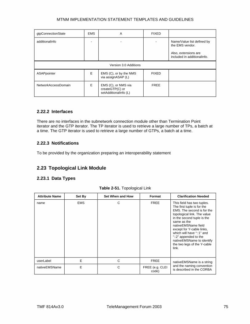
MTNM IMPLEMENTATION STATEMENT TEMPLATES AND GUIDELINES
TMF 814Av3.0 TeleManagement Forum 2003 75
gtpConnectionState EMS A FIXED
additionalInfo - - - Name/Value list defined by the EMS vendor.
Also, extensions are included in additionalInfo.
Version 3.0 Additions
ASAPpointer E EMS (C), or by the NMS via assignASAP (L)
FIXED
NetworkAccessDomain E EMS (C), or NMS via createGTP(C) or setAdditionalInfo (L)
FREE
2.22.2 Interfaces
There are no interfaces in the subnetwork connection module other than Termination Point iterator and the GTP iterator. The TP iterator is used to retrieve a large number of TPs, a batch at a time. The GTP iterator is used to retrieve a large number of GTPs, a batch at a time.
2.22.3 Notifications
To be provided by the organization preparing an interoperability statement
2.23 Topological Link Module
2.23.1 Data Types
Table 2-51. Topological Link
Attribute Name Set By Set When and How Format Clarification Needed
name EMS C FREE This field has two tuples. The first tuple is for the EMS. The second is for the topological link. The value in the second tuple is the same as the nativeEMSName field except for Y-cable links, which will have “::1” and “::2” appended to the nativeEMSName to identify the two legs of the Y-cable link.
userLabel E C FREE
nativeEMSName E C FREE (e.g. CLEI code)
nativeEMSName is a string and the naming convention is described in the CORBA
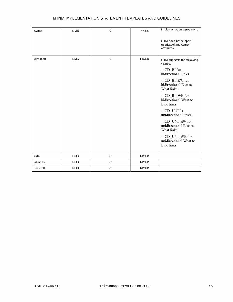
MTNM IMPLEMENTATION STATEMENT TEMPLATES AND GUIDELINES
TMF 814Av3.0 TeleManagement Forum 2003 76
owner NMS C FREE implementation agreement.
CTM does not support userLabel and owner attributes.
direction EMS C FIXED CTM supports the following values:
---- CD_BI for bidirectional links
---- CD_BI_EW for bidirectional East to West links
---- CD_BI_WE for bidirectional West to East links
---- CD_UNI for unidirectional links
---- CD_UNI_EW for unidirectional East to West links
---- CD_UNI_WE for unidirectional West to East links
rate EMS C FIXED
aEndTP EMS C FIXED
zEndTP EMS C FIXED
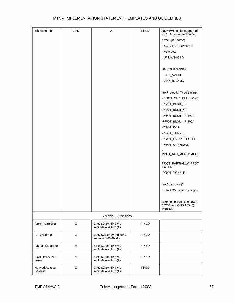
MTNM IMPLEMENTATION STATEMENT TEMPLATES AND GUIDELINES
TMF 814Av3.0 TeleManagement Forum 2003 77
additionalInfo EMS A FREE Name/Value list supported by CTM is defined below:
provType (name)
- AUTODISCOVERED
- MANUAL
- UNMANAGED
linkStatus (name)
- LINK_VALID
- LINK_INVALID
linkProtectionType (name)
- PROT_ONE_PLUS_ONE
-PROT_BLSR_2F
-PROT_BLSR_4F
-PROT_BLSR_2F_PCA
-PROT_BLSR_4F_PCA
-PROT_PCA
-PROT_TUNNEL
-PROT_UNPROTECTED
-PROT_UNKNOWN
-PROT_NOT_APPLICABLE
-PROT_PARTIALLY_PROTECTED
-PROT_YCABLE
linkCost (name)
- 0 to 1024 (values integer)
connectionType (on ONS 15530 and ONS 15540) Inter-NE
Version 3.0 Additions
AlarmReporting E EMS (C) or NMS via setAdditionalInfo (L)
FIXED
ASAPpointer E EMS (C), or by the NMS via assignASAP (L)
FIXED
AllocatedNumber E EMS (C) or NMS via setAdditionalInfo (L)
FIXED
FragmentServer Layer
E EMS (C) or NMS via setAdditionalInfo (L)
FIXED
NetworkAccess Domain
E EMS (C) or NMS via setAdditionalInfo (L)
FREE
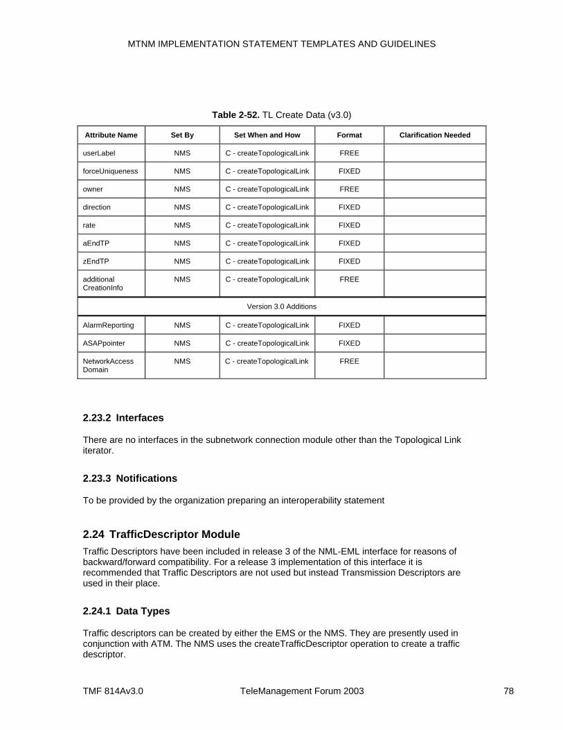
MTNM IMPLEMENTATION STATEMENT TEMPLATES AND GUIDELINES
TMF 814Av3.0 TeleManagement Forum 2003 78
Table 2-52. TL Create Data (v3.0)
Attribute Name Set By Set When and How Format Clarification Needed
userLabel NMS C - createTopologicalLink FREE
forceUniqueness NMS C - createTopologicalLink FIXED
owner NMS C - createTopologicalLink FREE
direction NMS C - createTopologicalLink FIXED
rate NMS C - createTopologicalLink FIXED
aEndTP NMS C - createTopologicalLink FIXED
zEndTP NMS C - createTopologicalLink FIXED
additional CreationInfo
NMS C - createTopologicalLink FREE
Version 3.0 Additions
AlarmReporting NMS C - createTopologicalLink FIXED
ASAPpointer NMS C - createTopologicalLink FIXED
NetworkAccess Domain
NMS C - createTopologicalLink FREE
2.23.2 Interfaces
There are no interfaces in the subnetwork connection module other than the Topological Link iterator.
2.23.3 Notifications
To be provided by the organization preparing an interoperability statement
2.24 TrafficDescriptor Module Traffic Descriptors have been included in release 3 of the NML-EML interface for reasons of backward/forward compatibility. For a release 3 implementation of this interface it is recommended that Traffic Descriptors are not used but instead Transmission Descriptors are used in their place.
2.24.1 Data Types
Traffic descriptors can be created by either the EMS or the NMS. They are presently used in conjunction with ATM. The NMS uses the createTrafficDescriptor operation to create a traffic descriptor.
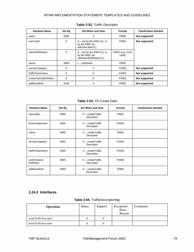
MTNM IMPLEMENTATION STATEMENT TEMPLATES AND GUIDELINES
TMF 814Av3.0 TeleManagement Forum 2003 79
Table 2-53. Traffic Descriptor
Attribute Name Set By Set When and How Format Clarification Needed
name EMS C FREE Not supported
userLabel E A – set by the EMS (C), or by the NMS via setUserLabel (L)
FREE
nativeEMSName E A – set by the EMS (C), or by the NMS via setNativeEMSName (L)
FREE (e.g. CLEI code)
owner NMS L – setOwner FREE
Not supported
serviceCategory E C FIXED Not supported
trafficParameters E C FIXED Not supported
conformanceDefinition E C FIXED Not supported
additionalInfo EMS A FREE Not supported
Table 2-54. TD Create Data
Attribute Name Set By Set When and How Format Clarification Needed
userLabel NMS C – createTraffic Descriptor
FREE
forceUniqueness NMS C – createTraffic Descriptor
FIXED
owner NMS C – createTraffic Descriptor
FREE
serviceCategory NMS C – createTraffic Descriptor
FIXED
trafficParameters NMS C – createTraffic Descriptor
FIXED
conformance Definition
NMS C – createTraffic Descriptor
FIXED
additionalInfo NMS C – createTraffic Descriptor
FREE
2.24.2 Interfaces
Table 2-55. TrafficDescriptorMgr
Operation Status Support Exception/ Error Reason
Comments
createTrafficDescriptor O N
deleteTrafficDescriptor O N
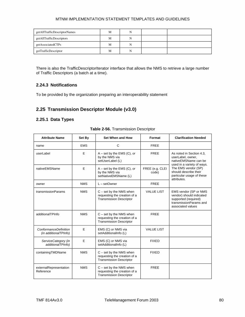
MTNM IMPLEMENTATION STATEMENT TEMPLATES AND GUIDELINES
TMF 814Av3.0 TeleManagement Forum 2003 80
getAllTrafficDescriptorNames M N
getAllTrafficDescriptors M N
getAssociatedCTPs M N
getTrafficDescriptor M N
There is also the TrafficDescriptorIterator interface that allows the NMS to retrieve a large number of Traffic Descriptors (a batch at a time).
2.24.3 Notifications
To be provided by the organization preparing an interoperability statement
2.25 Transmission Descriptor Module (v3.0)
2.25.1 Data Types
Table 2-56. Transmission Descriptor
Attribute Name Set By Set When and How Format Clarification Needed
name EMS C FREE
userLabel E A – set by the EMS (C), or by the NMS via setUserLabel (L)
FREE
nativeEMSName E A – set by the EMS (C), or by the NMS via setNativeEMSName (L)
FREE (e.g. CLEI code)
owner NMS L – setOwner FREE
As noted in Section 4.3, userLabel, owner, nativeEMSName can be used in a variety of ways. The EMS vendor (SP) should describe their particular usage of these attributes.
transmissionParams NMS C – set by the NMS when requesting the creation of a Transmission Descriptor
VALUE LIST EMS vendor (SP or NMS vendor) should indicated supported (required) transmissionParams and associated values
additionalTPInfo NMS C – set by the NMS when requesting the creation of a Transmission Descriptor
FREE
ConformanceDefinition (in additionalTPInfo)
E EMS (C) or NMS via setAdditionalInfo (L)
VALUE LIST
ServiceCategory (in additionalTPInfo)
E EMS (C) or NMS via setAdditionalInfo (L)
FIXED
containingTMDName NMS C – set by the NMS when requesting the creation of a Transmission Descriptor
FIXED
externalRepresentation Reference
NMS C – set by the NMS when requesting the creation of a Transmission Descriptor
FREE
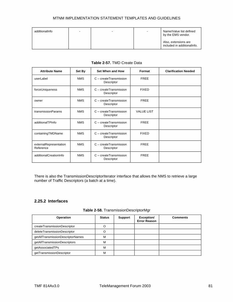
MTNM IMPLEMENTATION STATEMENT TEMPLATES AND GUIDELINES
TMF 814Av3.0 TeleManagement Forum 2003 81
additionalInfo - - - Name/Value list defined by the EMS vendor.
Also, extensions are included in additionalInfo.
Table 2-57. TMD Create Data
Attribute Name Set By Set When and How Format Clarification Needed
userLabel NMS C – createTransmission Descriptor
FREE
forceUniqueness NMS C – createTransmission Descriptor
FIXED
owner NMS C – createTransmission Descriptor
FREE
transmissionParams NMS C – createTransmission Descriptor
VALUE LIST
additionalTPInfo NMS C – createTransmission Descriptor
FREE
containingTMDName NMS C – createTransmission Descriptor
FIXED
externalRepresentation Reference
NMS C – createTransmission Descriptor
FREE
additionalCreationInfo NMS C – createTransmission Descriptor
FREE
There is also the TransmissionDescriptorIterator interface that allows the NMS to retrieve a large number of Traffic Descriptors (a batch at a time).
2.25.2 Interfaces
Table 2-58. TransmissionDescriptorMgr
Operation Status Support Exception/ Error Reason
Comments
createTransmissionDescriptor O
deleteTransmissionDescriptor O
getAllTransmissionDescriptorNames M
getAllTransmissionDescriptors M
getAssociatedTPs M
getTransmissionDescriptor M
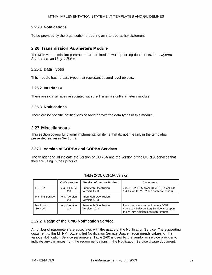
MTNM IMPLEMENTATION STATEMENT TEMPLATES AND GUIDELINES
TMF 814Av3.0 TeleManagement Forum 2003 82
2.25.3 Notifications
To be provided by the organization preparing an interoperability statement
2.26 Transmission Parameters Module The MTNM transmission parameters are defined in two supporting documents, i.e., Layered Parameters and Layer Rates.
2.26.1 Data Types
This module has no data types that represent second level objects.
2.26.2 Interfaces
There are no interfaces associated with the TransmissionParameters module.
2.26.3 Notifications
There are no specific notifications associated with the data types in this module.
2.27 Miscellaneous This section covers functional implementation items that do not fit easily in the templates presented earlier in Section 2.
2.27.1 Version of CORBA and CORBA Services
The vendor should indicate the version of CORBA and the version of the CORBA services that they are using in their product.
Table 2-59. CORBA Version
OMG Version Version of Vendor Product Comments
CORBA e.g., CORBA 2.3
Prismtech Openfusion Version 4.2.3
JacORB 2.1.3.5 (from CTM 6.0), (JacORB 1.4.1.x on CTM 5.2 and earlier releases)
Naming Service e.g., Version 2.3
Prismtech Openfusion Version 4.2.3
Notification Service
e.g., Version 2.3
Prismtech Openfusion Version 4.2.3
Note that a vendor could use a OMG compliant Telecom Log Service to support the MTNM notifications requirements.
2.27.2 Usage of the OMG Notification Service
A number of parameters are associated with the usage of the Notification Service. The supporting document to the MTNM IDL, entitled Notification Service Usage, recommends values for the various Notification Service parameters. Table 2-60 is used by the vendor or service provider to indicate any variances from the recommendations in the Notification Service Usage document.
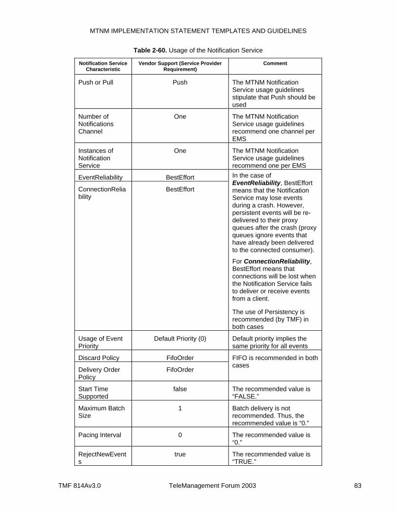
MTNM IMPLEMENTATION STATEMENT TEMPLATES AND GUIDELINES
TMF 814Av3.0 TeleManagement Forum 2003 83
Table 2-60. Usage of the Notification Service
Notification Service Characteristic
Vendor Support (Service Provider Requirement)
Comment
Push or Pull Push The MTNM Notification Service usage guidelines stipulate that Push should be used
Number of Notifications Channel
One The MTNM Notification Service usage guidelines recommend one channel per EMS
Instances of Notification Service
One The MTNM Notification Service usage guidelines recommend one per EMS
EventReliability BestEffort
ConnectionReliability
BestEffort
In the case of EventReliability, BestEffort means that the Notification Service may lose events during a crash. However, persistent events will be re-delivered to their proxy queues after the crash (proxy queues ignore events that have already been delivered to the connected consumer).
For ConnectionReliability, BestEffort means that connections will be lost when the Notification Service fails to deliver or receive events from a client.
The use of Persistency is recommended (by TMF) in both cases
Usage of Event Priority
Default Priority (0) Default priority implies the same priority for all events
Discard Policy FifoOrder
Delivery Order Policy
FifoOrder
FIFO is recommended in both cases
Start Time Supported
false The recommended value is “FALSE.”
Maximum Batch Size
1 Batch delivery is not recommended. Thus, the recommended value is “0.”
Pacing Interval 0 The recommended value is “0.”
RejectNewEvents
true The recommended value is “TRUE.”
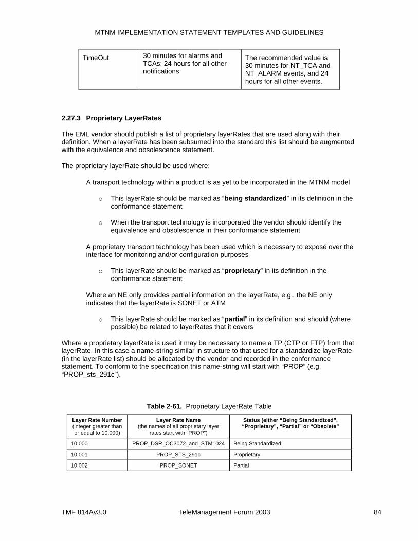
MTNM IMPLEMENTATION STATEMENT TEMPLATES AND GUIDELINES
TMF 814Av3.0 TeleManagement Forum 2003 84
TimeOut 30 minutes for alarms and TCAs; 24 hours for all other notifications
The recommended value is 30 minutes for NT_TCA and NT_ALARM events, and 24 hours for all other events.
2.27.3 Proprietary LayerRates
The EML vendor should publish a list of proprietary layerRates that are used along with their definition. When a layerRate has been subsumed into the standard this list should be augmented with the equivalence and obsolescence statement.
The proprietary layerRate should be used where:
A transport technology within a product is as yet to be incorporated in the MTNM model
o This layerRate should be marked as “being standardized” in its definition in the conformance statement
o When the transport technology is incorporated the vendor should identify the equivalence and obsolescence in their conformance statement
A proprietary transport technology has been used which is necessary to expose over the interface for monitoring and/or configuration purposes
o This layerRate should be marked as “proprietary” in its definition in the conformance statement
Where an NE only provides partial information on the layerRate, e.g., the NE only indicates that the layerRate is SONET or ATM
o This layerRate should be marked as “partial” in its definition and should (where possible) be related to layerRates that it covers
Where a proprietary layerRate is used it may be necessary to name a TP (CTP or FTP) from that layerRate. In this case a name-string similar in structure to that used for a standardize layerRate (in the layerRate list) should be allocated by the vendor and recorded in the conformance statement. To conform to the specification this name-string will start with “PROP” (e.g. “PROP_sts_291c”).
Table 2-61. Proprietary LayerRate Table
Layer Rate Number (integer greater than or equal to 10,000)
Layer Rate Name (the names of all proprietary layer
rates start with “PROP”)
Status (either “Being Standardized”, “Proprietary”, “Partial” or “Obsolete”
10,000 PROP_DSR_OC3072_and_STM1024 Being Standardized
10,001 PROP_STS_291c Proprietary
10,002 PROP_SONET Partial
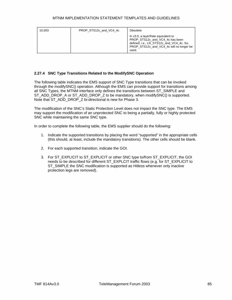
MTNM IMPLEMENTATION STATEMENT TEMPLATES AND GUIDELINES
TMF 814Av3.0 TeleManagement Forum 2003 85
10,003 PROP_STS12c_and_VC4_4c Obsolete
In v3.0, a layerRate equivalent to PROP_STS12c_and_VC4_4c has been defined, i.e., LR_STS12c_and_VC4_4c. So, PROP_STS12c_and_VC4_4c will no longer be used.
2.27.4 SNC Type Transitions Related to the ModifySNC Operation
The following table indicates the EMS support of SNC Type transitions that can be invoked through the modifySNC() operation. Although the EMS can provide support for transitions among all SNC Types, the MTNM interface only defines the transitions between ST_SIMPLE and ST_ADD_DROP_A or ST_ADD_DROP_Z to be mandatory, when modifySNC() is supported. Note that ST_ADD_DROP_Z bi-directional is new for Phase 3.
The modification of the SNC’s Static Protection Level does not impact the SNC type. The EMS may support the modification of an unprotected SNC to being a partially, fully or highly protected SNC while maintaining the same SNC type.
In order to complete the following table, the EMS supplier should do the following:
1. Indicate the supported transitions by placing the word “supported” in the appropriate cells (this should, at least, include the mandatory transitions). The other cells should be blank.
2. For each supported transition, indicate the GOI.
3. For ST_EXPLICIT to ST_EXPLICIT or other SNC type to/from ST_EXPLICIT, the GOI needs to be described for different ST_EXPLCIT traffic flows (e.g. for ST_EXPLICIT to ST_SIMPLE the SNC modification is supported as Hitless whenever only inactive protection legs are removed).
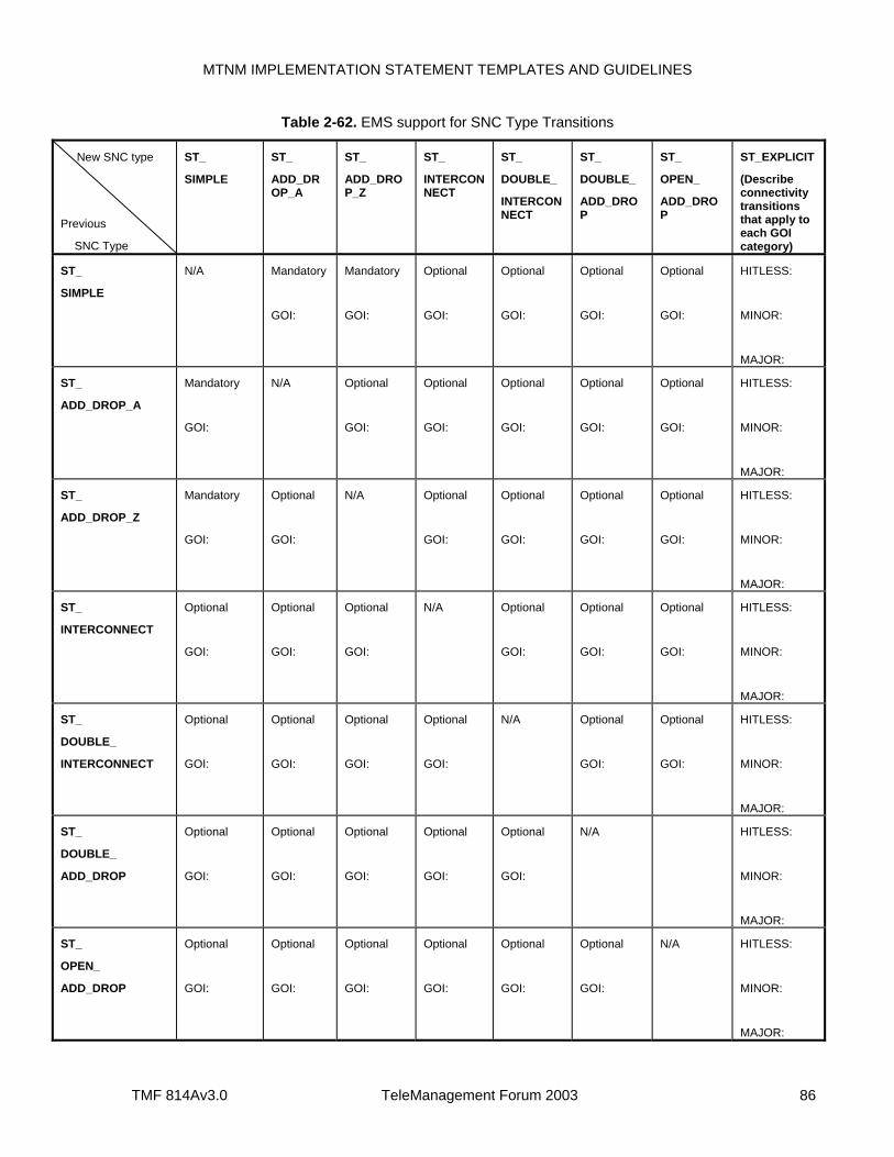
MTNM IMPLEMENTATION STATEMENT TEMPLATES AND GUIDELINES
TMF 814Av3.0 TeleManagement Forum 2003 86
Table 2-62. EMS support for SNC Type Transitions
New SNC type
Previous
SNC Type
ST_
SIMPLE
ST_
ADD_DROP_A
ST_
ADD_DROP_Z
ST_
INTERCONNECT
ST_
DOUBLE_
INTERCONNECT
ST_
DOUBLE_
ADD_DROP
ST_
OPEN_
ADD_DROP
ST_EXPLICIT
(Describe connectivity transitions that apply to each GOI category)
ST_
SIMPLE
N/A Mandatory
GOI:
Mandatory
GOI:
Optional
GOI:
Optional
GOI:
Optional
GOI:
Optional
GOI:
HITLESS:
MINOR:
MAJOR:
ST_
ADD_DROP_A
Mandatory
GOI:
N/A Optional
GOI:
Optional
GOI:
Optional
GOI:
Optional
GOI:
Optional
GOI:
HITLESS:
MINOR:
MAJOR:
ST_
ADD_DROP_Z
Mandatory
GOI:
Optional
GOI:
N/A Optional
GOI:
Optional
GOI:
Optional
GOI:
Optional
GOI:
HITLESS:
MINOR:
MAJOR:
ST_
INTERCONNECT
Optional
GOI:
Optional
GOI:
Optional
GOI:
N/A Optional
GOI:
Optional
GOI:
Optional
GOI:
HITLESS:
MINOR:
MAJOR:
ST_
DOUBLE_
INTERCONNECT
Optional
GOI:
Optional
GOI:
Optional
GOI:
Optional
GOI:
N/A Optional
GOI:
Optional
GOI:
HITLESS:
MINOR:
MAJOR:
ST_
DOUBLE_
ADD_DROP
Optional
GOI:
Optional
GOI:
Optional
GOI:
Optional
GOI:
Optional
GOI:
N/A HITLESS:
MINOR:
MAJOR:
ST_
OPEN_
ADD_DROP
Optional
GOI:
Optional
GOI:
Optional
GOI:
Optional
GOI:
Optional
GOI:
Optional
GOI:
N/A HITLESS:
MINOR:
MAJOR:

MTNM IMPLEMENTATION STATEMENT TEMPLATES AND GUIDELINES
TMF 814Av3.0 TeleManagement Forum 2003 87
ST_EXPLICIT HITLESS:
MINOR:
MAJOR:
HITLESS:
MINOR:
MAJOR:
HITLESS:
MINOR:
MAJOR:
HITLESS:
MINOR:
MAJOR:
HITLESS:
MINOR:
MAJOR:
HITLESS:
MINOR:
MAJOR:
HITLESS:
MINOR:
MAJOR:
N/A

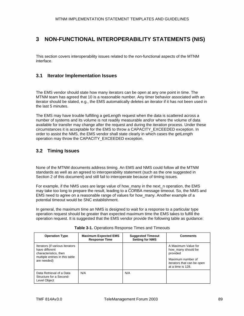
MTNM IMPLEMENTATION STATEMENT TEMPLATES AND GUIDELINES
TMF 814Av3.0 TeleManagement Forum 2003 89
3 NON-FUNCTIONAL INTEROPERABILITY STATEMENTS (NIS)
This section covers interoperability issues related to the non-functional aspects of the MTNM interface.
3.1 Iterator Implementation Issues
The EMS vendor should state how many iterators can be open at any one point in time. The MTNM team has agreed that 10 is a reasonable number. Any timer behavior associated with an iterator should be stated, e.g., the EMS automatically deletes an iterator if it has not been used in the last 5 minutes.
The EMS may have trouble fulfilling a getLength request when the data is scattered across a number of systems and its volume is not readily measurable and/or where the volume of data available for transfer may change after the request and during the iteration process. Under these circumstances it is acceptable for the EMS to throw a CAPACITY_EXCEEDED exception. In order to assist the NMS, the EMS vendor shall state clearly in which cases the getLength operation may throw the CAPACITY_EXCEEDED exception.
3.2 Timing Issues
None of the MTNM documents address timing. An EMS and NMS could follow all the MTNM standards as well as an agreed to interoperability statement (such as the one suggested in Section 2 of this document) and still fail to interoperate because of timing issues.
For example, if the NMS uses are large value of how_many in the next_n operation, the EMS may take too long to prepare the result, leading to a CORBA message timeout. So, the NMS and EMS need to agree on a reasonable range of values for how_many. Another example of a potential timeout would be SNC establishment.
In general, the maximum time an NMS is designed to wait for a response to a particular type operation request should be greater than expected maximum time the EMS takes to fulfill the operation request. It is suggested that the EMS vendor provide the following table as guidance:
Table 3-1. Operations Response Times and Timeouts
Operation Type Maximum Expected EMS Response Time
Suggested Timeout Setting for NMS
Comments
Iterators (if various iterators have different characteristics, then multiple entries in this table are needed)
A Maximum Value for how_many should be provided
Maximum number of iterators that can be open at a time is 128.
Data Retrieval of a Data Structure for a Second-Level Object
N/A N/A
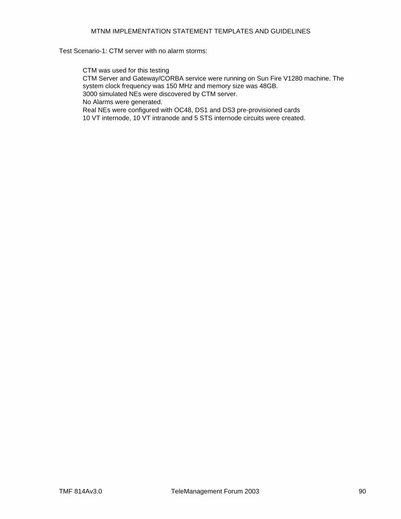
MTNM IMPLEMENTATION STATEMENT TEMPLATES AND GUIDELINES
TMF 814Av3.0 TeleManagement Forum 2003 90
Test Scenario-1: CTM server with no alarm storms:
CTM was used for this testing CTM Server and Gateway/CORBA service were running on Sun Fire V1280 machine. The
system clock frequency was 150 MHz and memory size was 48GB. 3000 simulated NEs were discovered by CTM server. No Alarms were generated. Real NEs were configured with OC48, DS1 and DS3 pre-provisioned cards 10 VT internode, 10 VT intranode and 5 STS internode circuits were created.
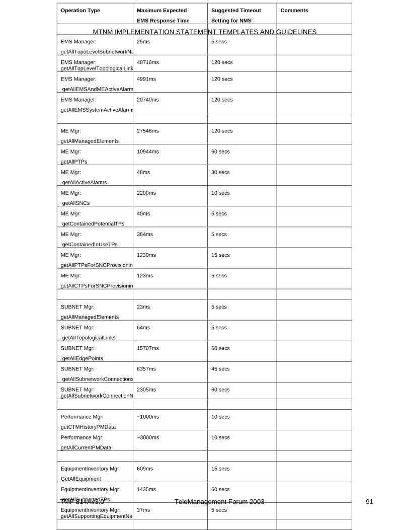
MTNM IMPLEMENTATION STATEMENT TEMPLATES AND GUIDELINES
TMF 814Av3.0 TeleManagement Forum 2003 91
Operation Type Maximum Expected
EMS Response Time
Suggested Timeout
Setting for NMS
Comments
EMS Manager:
getAllTopoLevelSubnetworkNa
25ms 5 secs
EMS Manager: getAllTopLevelTopologicalLink
40716ms 120 secs
EMS Manager:
getAllEMSAndMEActiveAlarm
4991ms 120 secs
EMS Manager:
getAllEMSSystemActiveAlarms
20740ms 120 secs
ME Mgr:
getAllManagedElements
27546ms 120 secs
ME Mgr:
getAllPTPs
10944ms 60 secs
ME Mgr:
getAllActiveAlarms
48ms 30 secs
ME Mgr:
getAllSNCs
2200ms 10 secs
ME Mgr:
getContainedPotentialTPs
40ms 5 secs
ME Mgr:
getContainedInUseTPs
384ms 5 secs
ME Mgr:
getAllPTPsForSNCProvisionin
1230ms 15 secs
ME Mgr:
getAllCTPsForSNCProvisionin
123ms 5 secs
SUBNET Mgr:
getAllManagedElements
23ms 5 secs
SUBNET Mgr:
getAllTopologicalLinks
64ms 5 secs
SUBNET Mgr:
getAllEdgePoints
15707ms 60 secs
SUBNET Mgr:
getAllSubnetworkConnections
6357ms 45 secs
SUBNET Mgr: getAllSubnetworkConnectionN
2305ms 60 secs
Performance Mgr:
getCTMHistoryPMData
~1000ms 10 secs
Performance Mgr:
getAllCurrentPMData
~3000ms 10 secs
EquipmentInventory Mgr:
GetAllEquipment
609ms 15 secs
EquipmentInventory Mgr:
getAllSupportedTPs
1435ms 60 secs
EquipmentInventory Mgr: getAllSupportingEquipmentNam
37ms 5 secs
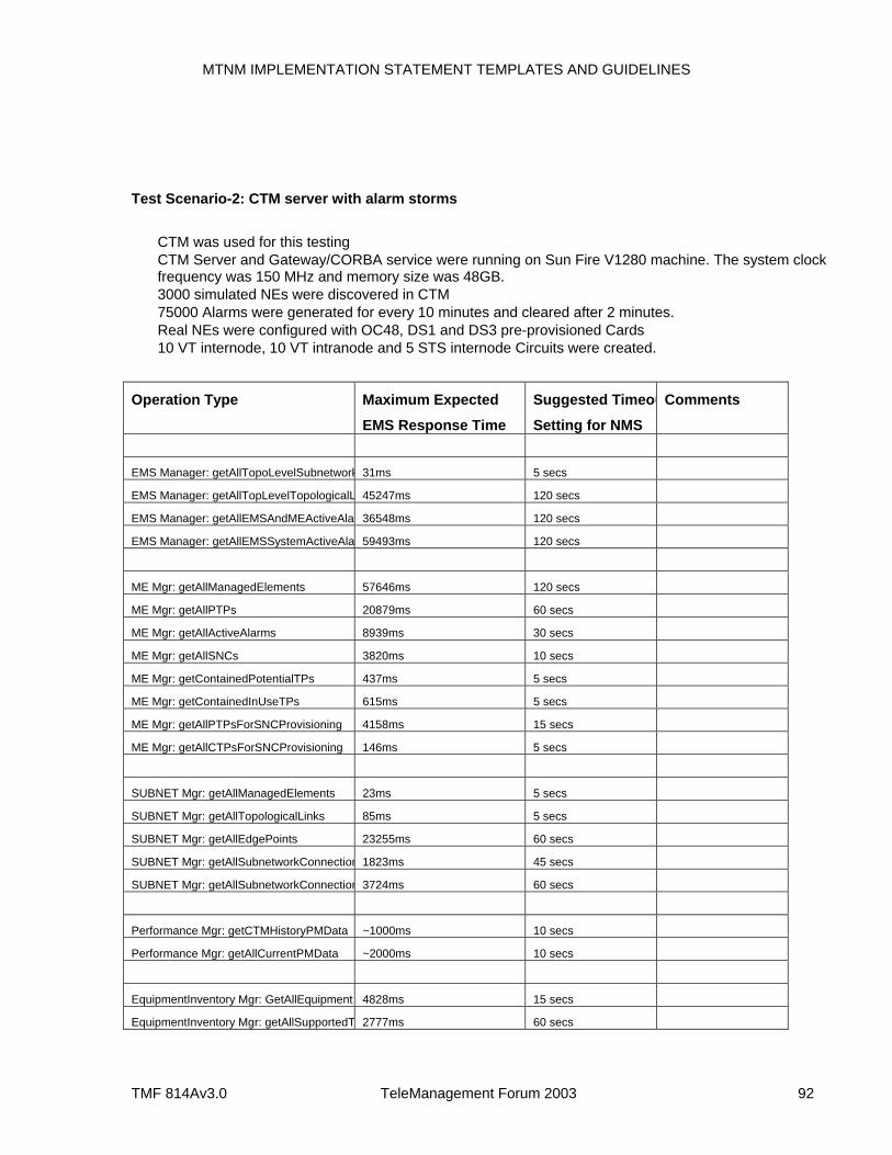
MTNM IMPLEMENTATION STATEMENT TEMPLATES AND GUIDELINES
TMF 814Av3.0 TeleManagement Forum 2003 92
Test Scenario-2: CTM server with alarm storms
CTM was used for this testing CTM Server and Gateway/CORBA service were running on Sun Fire V1280 machine. The system clock
frequency was 150 MHz and memory size was 48GB. 3000 simulated NEs were discovered in CTM 75000 Alarms were generated for every 10 minutes and cleared after 2 minutes. Real NEs were configured with OC48, DS1 and DS3 pre-provisioned Cards 10 VT internode, 10 VT intranode and 5 STS internode Circuits were created.
Operation Type Maximum Expected
EMS Response Time
Suggested Timeou
Setting for NMS
Comments
EMS Manager: getAllTopoLevelSubnetwork 31ms 5 secs
EMS Manager: getAllTopLevelTopologicalL 45247ms 120 secs
EMS Manager: getAllEMSAndMEActiveAla 36548ms 120 secs
EMS Manager: getAllEMSSystemActiveAla 59493ms 120 secs
ME Mgr: getAllManagedElements 57646ms 120 secs
ME Mgr: getAllPTPs 20879ms 60 secs
ME Mgr: getAllActiveAlarms 8939ms 30 secs
ME Mgr: getAllSNCs 3820ms 10 secs
ME Mgr: getContainedPotentialTPs 437ms 5 secs
ME Mgr: getContainedInUseTPs 615ms 5 secs
ME Mgr: getAllPTPsForSNCProvisioning 4158ms 15 secs
ME Mgr: getAllCTPsForSNCProvisioning 146ms 5 secs
SUBNET Mgr: getAllManagedElements 23ms 5 secs
SUBNET Mgr: getAllTopologicalLinks 85ms 5 secs
SUBNET Mgr: getAllEdgePoints 23255ms 60 secs
SUBNET Mgr: getAllSubnetworkConnection 1823ms 45 secs
SUBNET Mgr: getAllSubnetworkConnection 3724ms 60 secs
Performance Mgr: getCTMHistoryPMData ~1000ms 10 secs
Performance Mgr: getAllCurrentPMData ~2000ms 10 secs
EquipmentInventory Mgr: GetAllEquipment 4828ms 15 secs
EquipmentInventory Mgr: getAllSupportedT 2777ms 60 secs
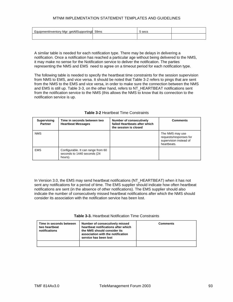
MTNM IMPLEMENTATION STATEMENT TEMPLATES AND GUIDELINES
TMF 814Av3.0 TeleManagement Forum 2003 93
EquipmentInventory Mgr: getAllSupportingE 59ms 5 secs
A similar table is needed for each notification type. There may be delays in delivering a notification. Once a notification has reached a particular age without being delivered to the NMS, it may make no sense for the Notification service to deliver the notification. The parties representing the NMS and EMS need to agree on a timeout period for each notification type.
The following table is needed to specify the heartbeat time constraints for the session supervision from NMS to EMS, and vice versa. It should be noted that Table 3-2 refers to pings that are sent from the NMS to the EMS and vice versa, in order to make sure the connection between the NMS and EMS is still up. Table 3-3, on the other hand, refers to NT_HEARTBEAT notifications sent from the notification service to the NMS (this allows the NMS to know that its connection to the notification service is up.
Table 3-2 Heartbeat Time Constraints
Supervising Partner
Time in seconds between two Heartbeat Messages
Number of consecutively failed Heartbeats after which the session is closed
Comments
NMS The NMS may use requests/responses for supervision instead of heartbeats.
EMS Configurable. It can range from 60 seconds to 1440 seconds (24 hours).
In Version 3.0, the EMS may send heartbeat notifications (NT_HEARTBEAT) when it has not sent any notifications for a period of time. The EMS supplier should indicate how often heartbeat notifications are sent (in the absence of other notifications). The EMS supplier should also indicate the number of consecutively missed heartbeat notifications after which the NMS should consider its association with the notification service has been lost.
Table 3-3. Heartbeat Notification Time Constraints
Time in seconds between two heartbeat notifications
Number of consecutively missed heartbeat notifications after which the NMS should consider its association with the notification service has been lost
Comments

MTNM IMPLEMENTATION STATEMENT TEMPLATES AND GUIDELINES
TMF 814Av3.0 TeleManagement Forum 2003 95
4 GUIDELINES This section covers guidelines concerning usage of the MTNM specifications. The intent is to describe, in further detail, the more complicated and/or less constrained aspects of the MTNM specifications. For example, the MTNM specifications state that subnetwork configuration is the responsibility of the EMS. Without further information, the NMS vendor needs to design their NMS to anticipate any of a number of possible subnetwork configuration schemes employed by various EMS vendors.
4.1 Implementation-specific Use Cases The MTNM Business Agreement document provides use cases for many management activities, e.g., NMS Provisions Alarm Monitoring Off, The NMS Creates a Subnetwork Connection, and Retrieval of Protection Group by the NMS. These use cases are not prescriptive and allow for many options. For a particular implementation of the NMS-EMS interface, it is recommended that the use cases be specialized and detailed in order to ensure greater interoperability between the NMS and EMS. The use cases in the MTNM BA could server as a basis for any product-specific use cases.
4.2 EMS Subnetwork Configuration In the MTNM model, the EMS decides how to package MEs into subnetworks. An understanding of how an EMS packages MEs into subnetwork will facilitate inventory discovery on the part of an NMS. Some examples concerning the packaging of the MEs within rings are as follows:
The EMS packages each ring (SONET, SDH, or DWDM) into a separate subnetwork. Open rings are packaged into separate subnetworks.
o In this case, the NMS will need to configure ring interconnection.
The EMS packages interconnected rings (having protected interconnection) into separate subnetworks (this could lead large mesh subnetworks), and all other rings into individual subnetworks. Open rings are packaged into separate subnetworks.
o In this case, the EMS (or the EMS GUI users) handles most of the configuration concerning ring interconnection.
In the first case above, each ring (or open ring) is in a separate subnetwork. For example, consider the case where a DSC is used to interconnect rings (say ring 1 and ring 2). The DSC is managed by one EMS and the rest of each ring is managed by another EMS. In this case, the NMS needs to setup three SNCs to get an end-to-end connection between a CTP in ring 1 and a CTP in ring 2. The SNCs in ring 1 and 2 would be of type ST_SIMPLE and the SNC in the DSC would be of type ST_DOUBLE_INTERCONNECT.
In the second case, the NMS only needs to request one SNC. In this case, the SNC type would be ST_DOUBLE_INTERCONNECT. This case is easier for the NMS since it does not need to know much about the internal structure of the mesh subnetwork (only needs to know that the mesh support DRI).
In the event subnetwork configuration is done via the EMS GUI, the EMS vendor may simply provide guidelines, suggestions and constraints concerning the configuration of subnetworks. In the event subnetwork configuration is performed via fixed logic in the EMS, the EMS vendor would an explanation of how the EMS decides on subnetwork packaging.
MTNM IMPLEMENTATION STATEMENT TEMPLATES AND GUIDELINES
TMF 814Av3.0 TeleManagement Forum 2003 96
4.3 Usage of the Various Resource Names The MTNM interface allows several identifiers to be assigned to a managed resource, i.e., name, userLabel, and nativeEMSName.
The name is assigned by the EMS and it is the unique identifier of resource to be used across the NMS-EMS interface. The NMS has no control over a resource’s name.
The userLabel is typically assigned by the NMS via the setUserLabel operation or a create operation for resources that can be created by an NMS request, e.g., SNCs. If a resource is created by the EMS (actually the interface object representing a resource), then the EMS sets the userLabel to the nativeEMSName.
o Further, the createSNC, createAndActivateSNC, checkValidSNC, and setUserLabel operations accept a parameter that allows the NMS to request that the EMS check the supplied userLabel for uniqueness. If the supplied userLabel is not unique, the request is rejected.
The nativeEMSName was originally intended to be the name of a resource as shown on an EMS display. This usage is not mandatory and other uses are possible. The nativeEMSName can be set by the EMS (typically through the EMS GUI) or it can be set by the NMS (if allowed by the EMS vendor) using the setNativeEMSName operation.
As an example use of the three resource names, consider the end-to-end connection shown in Figure 4-1 (as represented by the solid horizontal line). In this example, SNC AbcInc_3837 crosses three subnetworks, two of which are in one EMS domain (i.e., Subnetworks A and B are in EMS Domain 1) and the other subnetwork (i.e., C) is in another EMS domain (i.e., Domain 2). The EMS uses the Name attribute to uniquely identify an SNC within its domain (this is always true for EMSs that follow the MTNM interface specifications). The network provider uses the NativeEMSName to store its identifier for an SNC. The NativeEMSName can be assigned via the EMS GUI or through the setNativeEMSName operations. The service provider uses the userLabel to associate the three SNCs that comprise the end-to-end connection. In this case, the NMS does not want to force uniqueness of the userLabel. Of course, the NMS could use its own internal mechanism to associate connections that cross several subnetworks. The advantages of using the userLabel in this case are as follows:
If the NMS fails, the EMS user can still determine the association among related SNCs in different subnetworks (the EMS GUI would need to have appropriate search functions). If the connection crosses multiple EMS domains, correlation becomes more complicated and is likely to require more analysis on the part of the EMS user.
If the NMS fails, the EMS GUI could be used to create connections crossing multiple subnetworks. After it has recovered, the NMS could discover the SNC associations by looking at the userLabels of the newly created SNCs.
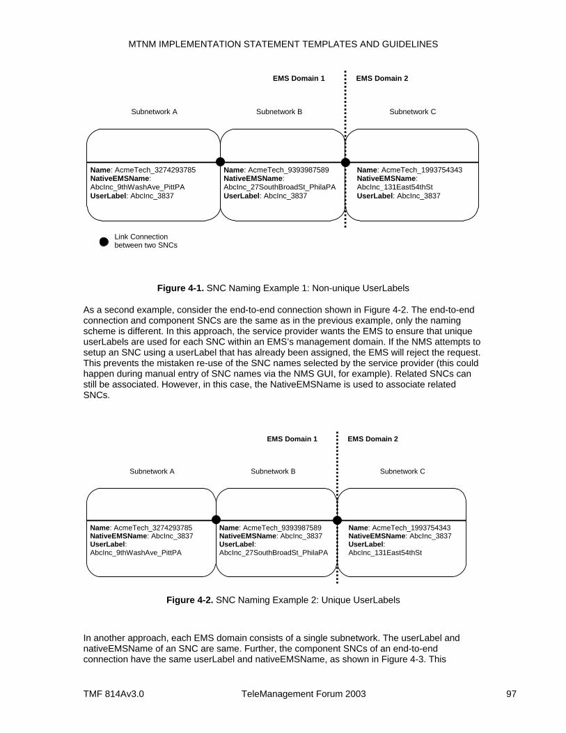
MTNM IMPLEMENTATION STATEMENT TEMPLATES AND GUIDELINES
TMF 814Av3.0 TeleManagement Forum 2003 97
Name: AcmeTech_3274293785 NativeEMSName: AbcInc_9thWashAve_PittPA UserLabel: AbcInc_3837
EMS Domain 1
Subnetwork B
EMS Domain 2
Name: AcmeTech_9393987589 NativeEMSName: AbcInc_27SouthBroadSt_PhilaPA UserLabel: AbcInc_3837
Name: AcmeTech_1993754343 NativeEMSName: AbcInc_131East54thSt UserLabel: AbcInc_3837
Subnetwork A Subnetwork C
Link Connection between two SNCs
Figure 4-1. SNC Naming Example 1: Non-unique UserLabels
As a second example, consider the end-to-end connection shown in Figure 4-2. The end-to-end connection and component SNCs are the same as in the previous example, only the naming scheme is different. In this approach, the service provider wants the EMS to ensure that unique userLabels are used for each SNC within an EMS’s management domain. If the NMS attempts to setup an SNC using a userLabel that has already been assigned, the EMS will reject the request. This prevents the mistaken re-use of the SNC names selected by the service provider (this could happen during manual entry of SNC names via the NMS GUI, for example). Related SNCs can still be associated. However, in this case, the NativeEMSName is used to associate related SNCs.
Name: AcmeTech_3274293785 NativeEMSName: AbcInc_3837 UserLabel: AbcInc_9thWashAve_PittPA
EMS Domain 1
Subnetwork B
EMS Domain 2
Name: AcmeTech_9393987589 NativeEMSName: AbcInc_3837 UserLabel: AbcInc_27SouthBroadSt_PhilaPA
Name: AcmeTech_1993754343 NativeEMSName: AbcInc_3837 UserLabel: AbcInc_131East54thSt
Subnetwork A Subnetwork C
Figure 4-2. SNC Naming Example 2: Unique UserLabels
In another approach, each EMS domain consists of a single subnetwork. The userLabel and nativeEMSName of an SNC are same. Further, the component SNCs of an end-to-end connection have the same userLabel and nativeEMSName, as shown in Figure 4-3. This
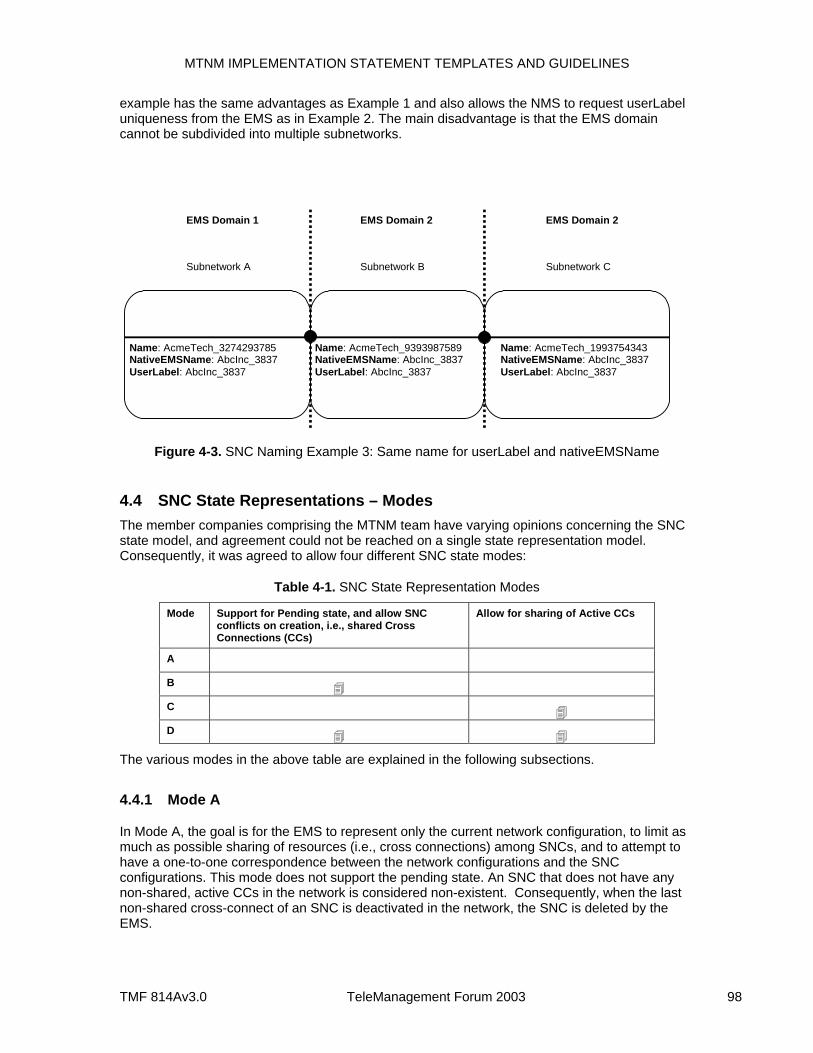
MTNM IMPLEMENTATION STATEMENT TEMPLATES AND GUIDELINES
TMF 814Av3.0 TeleManagement Forum 2003 98
example has the same advantages as Example 1 and also allows the NMS to request userLabel uniqueness from the EMS as in Example 2. The main disadvantage is that the EMS domain cannot be subdivided into multiple subnetworks.
Name: AcmeTech_3274293785 NativeEMSName: AbcInc_3837 UserLabel: AbcInc_3837
EMS Domain 1
Subnetwork B
EMS Domain 2
Name: AcmeTech_9393987589 NativeEMSName: AbcInc_3837 UserLabel: AbcInc_3837
Name: AcmeTech_1993754343 NativeEMSName: AbcInc_3837 UserLabel: AbcInc_3837
Subnetwork A Subnetwork C
EMS Domain 2
Figure 4-3. SNC Naming Example 3: Same name for userLabel and nativeEMSName
4.4 SNC State Representations – Modes The member companies comprising the MTNM team have varying opinions concerning the SNC state model, and agreement could not be reached on a single state representation model. Consequently, it was agreed to allow four different SNC state modes:
Table 4-1. SNC State Representation Modes
Mode Support for Pending state, and allow SNC conflicts on creation, i.e., shared Cross Connections (CCs)
Allow for sharing of Active CCs
A B C D
The various modes in the above table are explained in the following subsections.
4.4.1 Mode A
In Mode A, the goal is for the EMS to represent only the current network configuration, to limit as much as possible sharing of resources (i.e., cross connections) among SNCs, and to attempt to have a one-to-one correspondence between the network configurations and the SNC configurations. This mode does not support the pending state. An SNC that does not have any non-shared, active CCs in the network is considered non-existent. Consequently, when the last non-shared cross-connect of an SNC is deactivated in the network, the SNC is deleted by the EMS.
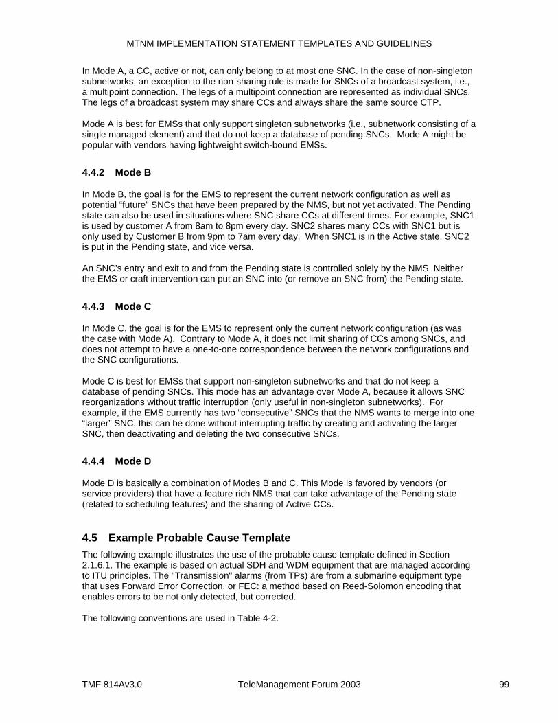
MTNM IMPLEMENTATION STATEMENT TEMPLATES AND GUIDELINES
TMF 814Av3.0 TeleManagement Forum 2003 99
In Mode A, a CC, active or not, can only belong to at most one SNC. In the case of non-singleton subnetworks, an exception to the non-sharing rule is made for SNCs of a broadcast system, i.e., a multipoint connection. The legs of a multipoint connection are represented as individual SNCs. The legs of a broadcast system may share CCs and always share the same source CTP.
Mode A is best for EMSs that only support singleton subnetworks (i.e., subnetwork consisting of a single managed element) and that do not keep a database of pending SNCs. Mode A might be popular with vendors having lightweight switch-bound EMSs.
4.4.2 Mode B
In Mode B, the goal is for the EMS to represent the current network configuration as well as potential “future” SNCs that have been prepared by the NMS, but not yet activated. The Pending state can also be used in situations where SNC share CCs at different times. For example, SNC1 is used by customer A from 8am to 8pm every day. SNC2 shares many CCs with SNC1 but is only used by Customer B from 9pm to 7am every day. When SNC1 is in the Active state, SNC2 is put in the Pending state, and vice versa.
An SNC’s entry and exit to and from the Pending state is controlled solely by the NMS. Neither the EMS or craft intervention can put an SNC into (or remove an SNC from) the Pending state.
4.4.3 Mode C
In Mode C, the goal is for the EMS to represent only the current network configuration (as was the case with Mode A). Contrary to Mode A, it does not limit sharing of CCs among SNCs, and does not attempt to have a one-to-one correspondence between the network configurations and the SNC configurations.
Mode C is best for EMSs that support non-singleton subnetworks and that do not keep a database of pending SNCs. This mode has an advantage over Mode A, because it allows SNC reorganizations without traffic interruption (only useful in non-singleton subnetworks). For example, if the EMS currently has two “consecutive” SNCs that the NMS wants to merge into one “larger” SNC, this can be done without interrupting traffic by creating and activating the larger SNC, then deactivating and deleting the two consecutive SNCs.
4.4.4 Mode D
Mode D is basically a combination of Modes B and C. This Mode is favored by vendors (or service providers) that have a feature rich NMS that can take advantage of the Pending state (related to scheduling features) and the sharing of Active CCs.
4.5 Example Probable Cause Template The following example illustrates the use of the probable cause template defined in Section 2.1.6.1. The example is based on actual SDH and WDM equipment that are managed according to ITU principles. The "Transmission" alarms (from TPs) are from a submarine equipment type that uses Forward Error Correction, or FEC: a method based on Reed-Solomon encoding that enables errors to be not only detected, but corrected.
The following conventions are used in Table 4-2.
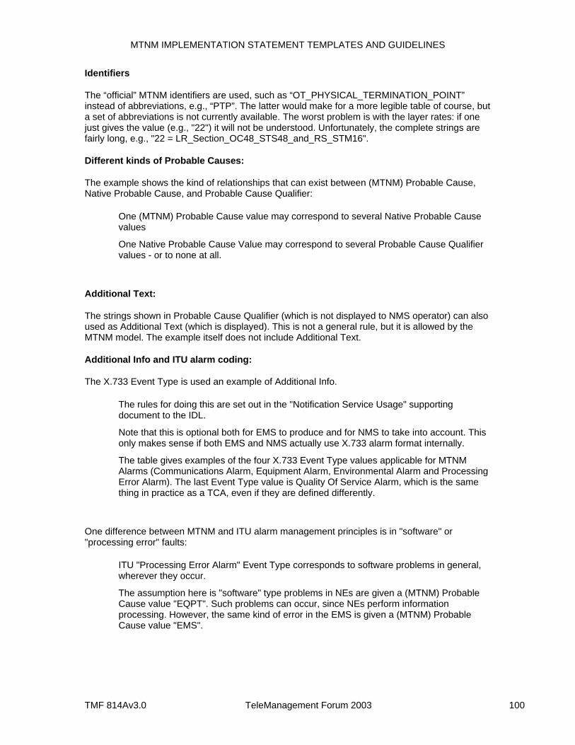
MTNM IMPLEMENTATION STATEMENT TEMPLATES AND GUIDELINES
TMF 814Av3.0 TeleManagement Forum 2003 100
Identifiers
The “official” MTNM identifiers are used, such as “OT_PHYSICAL_TERMINATION_POINT” instead of abbreviations, e.g., “PTP”. The latter would make for a more legible table of course, but a set of abbreviations is not currently available. The worst problem is with the layer rates: if one just gives the value (e.g., "22") it will not be understood. Unfortunately, the complete strings are fairly long, e.g., "22 = LR_Section_OC48_STS48_and_RS_STM16".
Different kinds of Probable Causes:
The example shows the kind of relationships that can exist between (MTNM) Probable Cause, Native Probable Cause, and Probable Cause Qualifier:
One (MTNM) Probable Cause value may correspond to several Native Probable Cause values
One Native Probable Cause Value may correspond to several Probable Cause Qualifier values - or to none at all.
Additional Text:
The strings shown in Probable Cause Qualifier (which is not displayed to NMS operator) can also used as Additional Text (which is displayed). This is not a general rule, but it is allowed by the MTNM model. The example itself does not include Additional Text.
Additional Info and ITU alarm coding:
The X.733 Event Type is used an example of Additional Info.
The rules for doing this are set out in the "Notification Service Usage" supporting document to the IDL.
Note that this is optional both for EMS to produce and for NMS to take into account. This only makes sense if both EMS and NMS actually use X.733 alarm format internally.
The table gives examples of the four X.733 Event Type values applicable for MTNM Alarms (Communications Alarm, Equipment Alarm, Environmental Alarm and Processing Error Alarm). The last Event Type value is Quality Of Service Alarm, which is the same thing in practice as a TCA, even if they are defined differently.
One difference between MTNM and ITU alarm management principles is in "software" or "processing error" faults:
ITU "Processing Error Alarm" Event Type corresponds to software problems in general, wherever they occur.
The assumption here is "software" type problems in NEs are given a (MTNM) Probable Cause value "EQPT". Such problems can occur, since NEs perform information processing. However, the same kind of error in the EMS is given a (MTNM) Probable Cause value "EMS".
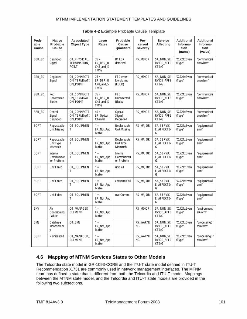
MTNM IMPLEMENTATION STATEMENT TEMPLATES AND GUIDELINES
TMF 814Av3.0 TeleManagement Forum 2003 101
Table 4-2 Example Probable Cause Template
Prob-able Cause
Native Probable
Cause
Associated Object Type
Layer Rates
Probable Cause
Qualifiers
Per-ceived
Severity
Service Affecting
Additional Informa-
tion (name)
Additional Informa-
tion (value)
BER_SD Degraded Signal
OT_PHYSICAL_TERMINATION_POINT
76 = LR_DSR_OC48_and_STM16
B1 LER detected
PS_MINOR SA_NON_SERVICE_AFFECTING
"X.721::EventType"
"communicationsAlarm"
BER_SD Degraded Signal
OT_CONNECTION_TERMINATION_POINT
76 = LR_DSR_OC48_and_STM16
FEC error low alarms (LBER)
PS_MINOR SA_NON_SERVICE_AFFECTING
"X.721::EventType"
"communicationsAlarm"
BER_SD Fec Uncorrected Blocks
OT_CONNECTION_TERMINATION_POINT
76 = LR_DSR_OC48_and_STM16
FEC Uncorrected Blocks
PS_MINOR SA_NON_SERVICE_AFFECTING
"X.721::EventType"
"communicationsAlarm"
BER_SD Optical Signal Degraded
OT_CONNECTION_TERMINATION_POINT
40 = LR_Optical_Channel
Optical Signal Degraded
PS_MINOR SA_NON_SERVICE_AFFECTING
"X.721::EventType"
"communicationsAlarm"
EQPT Replaceable Unit Missing
OT_EQUIPMENT
1 = LR_Not_Applicable
Replaceable Unit Missing
PS_MAJOR SA_SERVICE_AFFECTING
"X.721::EventType"
"equipmentAlarm"
EQPT Replaceable Unit Type Mismatch
OT_EQUIPMENT
1 = LR_Not_Applicable
Replaceable Unit Type Mismatch
PS_MAJOR SA_SERVICE_AFFECTING
"X.721::EventType"
"equipmentAlarm"
EQPT Internal Communication Problem
OT_EQUIPMENT
1 = LR_Not_Applicable
Internal Communication Problem
PS_MAJOR SA_SERVICE_AFFECTING
"X.721::EventType"
"equipmentAlarm"
EQPT Unit Failed OT_EQUIPMENT
1 = LR_Not_Applicable
unitFail PS_MAJOR SA_SERVICE_AFFECTING
"X.721::EventType"
"equipmentAlarm"
EQPT Unit Failed OT_EQUIPMENT
1 = LR_Not_Applicable
converterFail PS_MAJOR SA_SERVICE_AFFECTING
"X.721::EventType"
"equipmentAlarm"
EQPT Unit Failed OT_EQUIPMENT
1 = LR_Not_Applicable
overCurrent PS_MAJOR SA_SERVICE_AFFECTING
"X.721::EventType"
"equipmentAlarm"
ENV Air Conditioning Failure
OT_MANAGED_ELEMENT
1 = LR_Not_Applicable
PS_MINOR SA_NON_SERVICE_AFFECTING
"X.721::EventType"
"environmentalAlarm"
EMS Database Inconsistency
OT_EMS 1 = LR_Not_Applicable
PS_WARNING
SA_NON_SERVICE_AFFECTING
"X.721::EventType"
"processingErrorAlarm"
EQPT Reinitialized OT_MANAGED_ELEMENT
1 = LR_Not_Applicable
PS_WARNING
SA_NON_SERVICE_AFFECTING
"X.721::EventType"
"processingErrorAlarm"
4.6 Mapping of MTNM Services States to Other Models The Telcordia state model in GR-1093-CORE and the ITU-T state model defined in ITU-T Recommendation X.731 are commonly used in network management interfaces. The MTNM team has defined a state that is different from both the Telcordia and ITU-T model. Mappings between the MTNM state model, and the Telcordia and ITU-T state models are provided in the following two subsections.
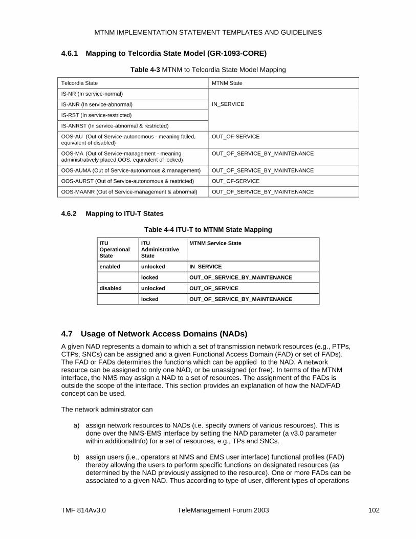
MTNM IMPLEMENTATION STATEMENT TEMPLATES AND GUIDELINES
TMF 814Av3.0 TeleManagement Forum 2003 102
4.6.1 Mapping to Telcordia State Model (GR-1093-CORE)
Table 4-3 MTNM to Telcordia State Model Mapping
Telcordia State MTNM State
IS-NR (In service-normal)
IS-ANR (In service-abnormal)
IS-RST (In service-restricted)
IS-ANRST (In service-abnormal & restricted)
IN_SERVICE
OOS-AU (Out of Service-autonomous - meaning failed, equivalent of disabled)
OUT_OF-SERVICE
OOS-MA (Out of Service-management - meaning administratively placed OOS, equivalent of locked)
OUT_OF_SERVICE_BY_MAINTENANCE
OOS-AUMA (Out of Service-autonomous & management) OUT_OF_SERVICE_BY_MAINTENANCE
OOS-AURST (Out of Service-autonomous & restricted) OUT_OF-SERVICE
OOS-MAANR (Out of Service-management & abnormal) OUT_OF_SERVICE_BY_MAINTENANCE
4.6.2 Mapping to ITU-T States
Table 4-4 ITU-T to MTNM State Mapping
ITU Operational State
ITU Administrative State
MTNM Service State
enabled unlocked IN_SERVICE
locked OUT_OF_SERVICE_BY_MAINTENANCE
disabled unlocked OUT_OF_SERVICE
locked OUT_OF_SERVICE_BY_MAINTENANCE
4.7 Usage of Network Access Domains (NADs) A given NAD represents a domain to which a set of transmission network resources (e.g., PTPs, CTPs, SNCs) can be assigned and a given Functional Access Domain (FAD) or set of FADs). The FAD or FADs determines the functions which can be applied to the NAD. A network resource can be assigned to only one NAD, or be unassigned (or free). In terms of the MTNM interface, the NMS may assign a NAD to a set of resources. The assignment of the FADs is outside the scope of the interface. This section provides an explanation of how the NAD/FAD concept can be used.
The network administrator can
a) assign network resources to NADs (i.e. specify owners of various resources). This is done over the NMS-EMS interface by setting the NAD parameter (a v3.0 parameter within additionalInfo) for a set of resources, e.g., TPs and SNCs.
b) assign users (i.e., operators at NMS and EMS user interface) functional profiles (FAD) thereby allowing the users to perform specific functions on designated resources (as determined by the NAD previously assigned to the resource). One or more FADs can be associated to a given NAD. Thus according to type of user, different types of operations
MTNM IMPLEMENTATION STATEMENT TEMPLATES AND GUIDELINES
TMF 814Av3.0 TeleManagement Forum 2003 103
are permitted on the specific NAD. Again, management of the FADs is outside the scope of the MTNM interface.
A given resource with its NetworkAccessDomain parameter set to the empty string is intended to be a “free” resource, i.e., any users can request only MTNM operation on the resource. A given FAD can be defined to permit or refuse access to “free” resources.
Example use of NADs and FADs:
some resources are marked for the NetworkAccessDomain = ”owner23”
user44 is defined by the network administrator at the EMS to be associated with FAD = “readonly” and to be given access to the “owner23” NAD. So, on the EMS side, “user44” is granted readonly access to the TPs and SNCs belonging to NAD = “owner23”.
As another example, it is noted that the NAD/FAD mechanism can be used to define VPNs. In fact, a given VPN could be seen as NAD, where the VPN operator can create/activate, and deactivate/delete SNCs using only the routing resources belonging to such NAD/VPN (e.g., the NMS could include the NAD identifier in the additionalCreationInfo parameter of the createAndActivateSNC operation). At the EMS level, an SNC can be routed only on resources (CTPs) which NetworkAccessDomain value is equal to such NAD/VPN (or is “free”, if the FAD allows it).
4.8 Root Cause Alarm Indication The Root Cause Alarm Indication (RCAI) feature allows the EMS to indicate a distinction between raw (i.e., un-correlated) alarms, and root cause alarm indications.
The NMS can use the filtering capability of the Notification Service in conjunction with the RCAI field to
receive only raw alarms, i.e., alarms with the root cause alarm field set to FALSE,
receive only RCAIs, i.e., alarms with the root cause alarm field set to TRUE, or
receive both raw alarms and RCAIs.
The following suggestions are noted concerning usage of the RCAI:
1. If a single alarm persists but does not get correlated with any other alarm, two notifications are expected (the raw alarm and the RCAI associated with the uncorrelated raw alarm).
2. There is no field in the RCAI or the raw alarms that points to the other correlated alarms. The idea is to keep the interface as simple as possible and still allow for the reporting of RCAIs.
3. The raw alarms result in notifications immediately. The RCAI is generated after the correlation window closes (the length of the correlation window is an implementation issue for the EMS/NE vendor).
4. RCAIs usually clear after all related raw alarms clear and stay cleared for a persistence interval.
The above points are just suggestions concerning how the RCAI feature could work. Since these suggestions relate to EMS implementation, they are not included in the requirements of the Business Agreement document.
MTNM IMPLEMENTATION STATEMENT TEMPLATES AND GUIDELINES
TMF 814Av3.0 TeleManagement Forum 2003 104
ITU-T Recommendation M.2140, Transport Network Event Correlation, provides additional detail concerning how RCAI might be supported.
Some common questions and answers concerning the proposed model:
Doesn’t a notification need to be sent when a raw alarm latter gets declared as a root cause?
In the proposed model, raw alarms do not "change" to root causes. If the root cause of several alarms is identified to be the same as a previous raw alarm, a new root cause alarm indication could be sent to the NMS. Both the original raw alarm and the root cause would be treated as separate alarms in terms of notifications sent over the EMS-NMS interface. Each would be cleared separately.
What notification is sent when a previously declared root cause is now related to another root cause?
If the EMS decides that it has found a better root cause, the EMS could clear the original root cause and declare a new root cause.
4.9 FTP Examples In order to represent managed element with several layers of flexibility, the MTNM team has added support for Floating TPs in v3.0.
An example managed element with several layers of flexibility is shown in Figure 4-4 and Figure 4-5. (Figure 4-4 is the usual "elevation" figure where layers are shown stacked vertically one above the other - server layers are always beneath client layers. Figure 4-5 is a "plane" figure where the layout is "horizontal", as if all the lines in Figure 4-4 were twisted to make them parallel. This allows multiplexing to be shown, and is easier to relate to hardware. [Note that Figure 4-5 shows four VC4 ports whereas Figure 4-4 shows only VC4 port.] The figures use the graphical conventions of ITU-T documents such as G.805. Figure 4-4 shows, from right to left:
An SDH port (layers are modeled according to TMF MTNM, to facilitate comparison with the following figures. These layers are: Physical, Optical Section, Digital Signal Rate, Regeneration Section, Multiplex Section);
A High Order Matrix with a flexible cross-connection at AU4 / VC4 (SONET: STS3c) level;
The VC4 TTP, comprising termination function and adaptation function, with mapping to 3 TU3's;
A Low Order Matrix with a flexible cross-connection at TU3 / VC3 (SONET: STS1) level;
A fixed connection at 45Mbit (DS3) tributary level;
A PDH port (with layers: Phy, DSR, 45M).
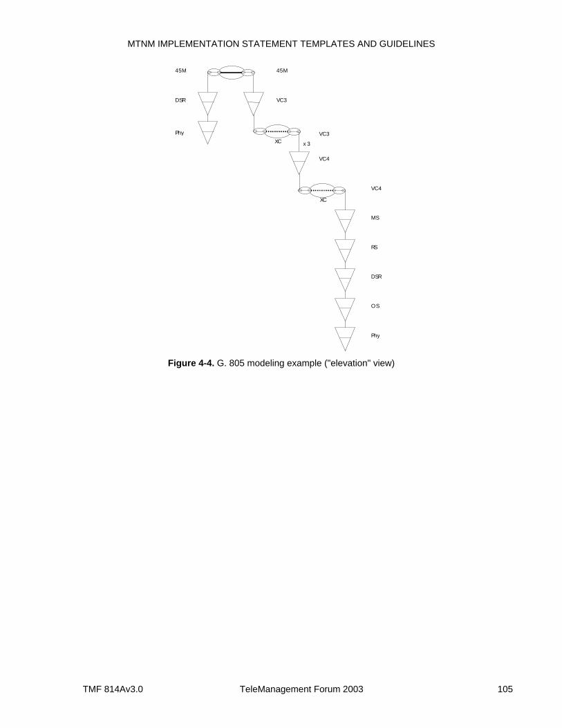
MTNM IMPLEMENTATION STATEMENT TEMPLATES AND GUIDELINES
TMF 814Av3.0 TeleManagement Forum 2003 105
Phy
DSR
45M
VC3
VC4
VC4
VC3
45M
MS
RS
DSR
OS
Phy
x 3XC
XC
Figure 4-4. G. 805 modeling example ("elevation" view)
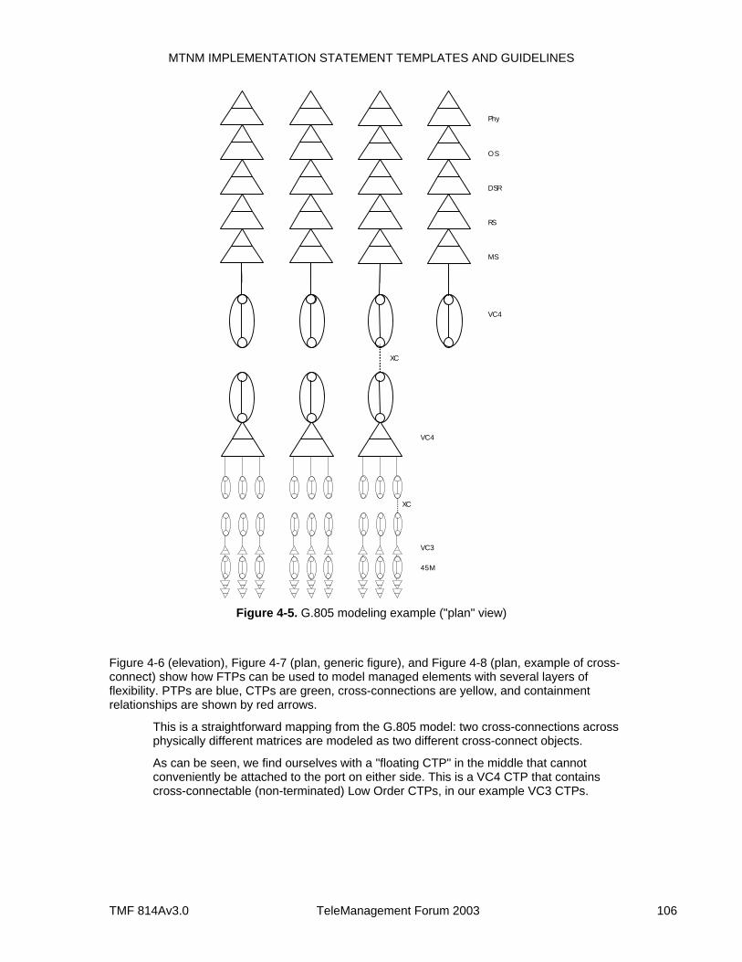
MTNM IMPLEMENTATION STATEMENT TEMPLATES AND GUIDELINES
TMF 814Av3.0 TeleManagement Forum 2003 106
VC4
MS
RS
DSR
OS
Phy
VC3
VC4
45M
XC
XC
Figure 4-5. G.805 modeling example ("plan" view)
Figure 4-6 (elevation), Figure 4-7 (plan, generic figure), and Figure 4-8 (plan, example of cross-connect) show how FTPs can be used to model managed elements with several layers of flexibility. PTPs are blue, CTPs are green, cross-connections are yellow, and containment relationships are shown by red arrows.
This is a straightforward mapping from the G.805 model: two cross-connections across physically different matrices are modeled as two different cross-connect objects.
As can be seen, we find ourselves with a "floating CTP" in the middle that cannot conveniently be attached to the port on either side. This is a VC4 CTP that contains cross-connectable (non-terminated) Low Order CTPs, in our example VC3 CTPs.
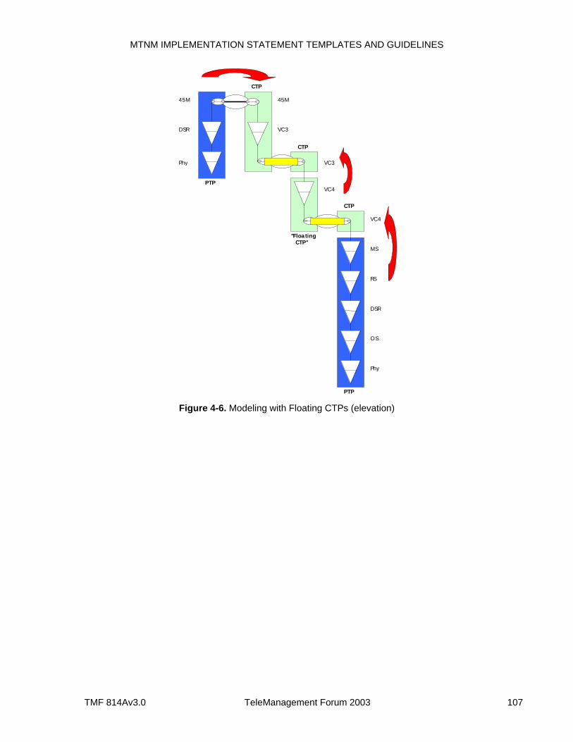
MTNM IMPLEMENTATION STATEMENT TEMPLATES AND GUIDELINES
TMF 814Av3.0 TeleManagement Forum 2003 107
Phy
DSR
45M
VC3
VC4
VC4
VC3
45M
MS
RS
DSR
OS
Phy
PTP
PTP
CTP
CTP
"FloatingCTP"
CTP
Figure 4-6. Modeling with Floating CTPs (elevation)
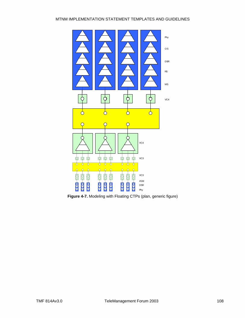
MTNM IMPLEMENTATION STATEMENT TEMPLATES AND GUIDELINES
TMF 814Av3.0 TeleManagement Forum 2003 108
VC4
MS
RS
DSR
OS
Phy
VC4
Phy
DSR
VC3
45M
VC3
Figure 4-7. Modeling with Floating CTPs (plan, generic figure)
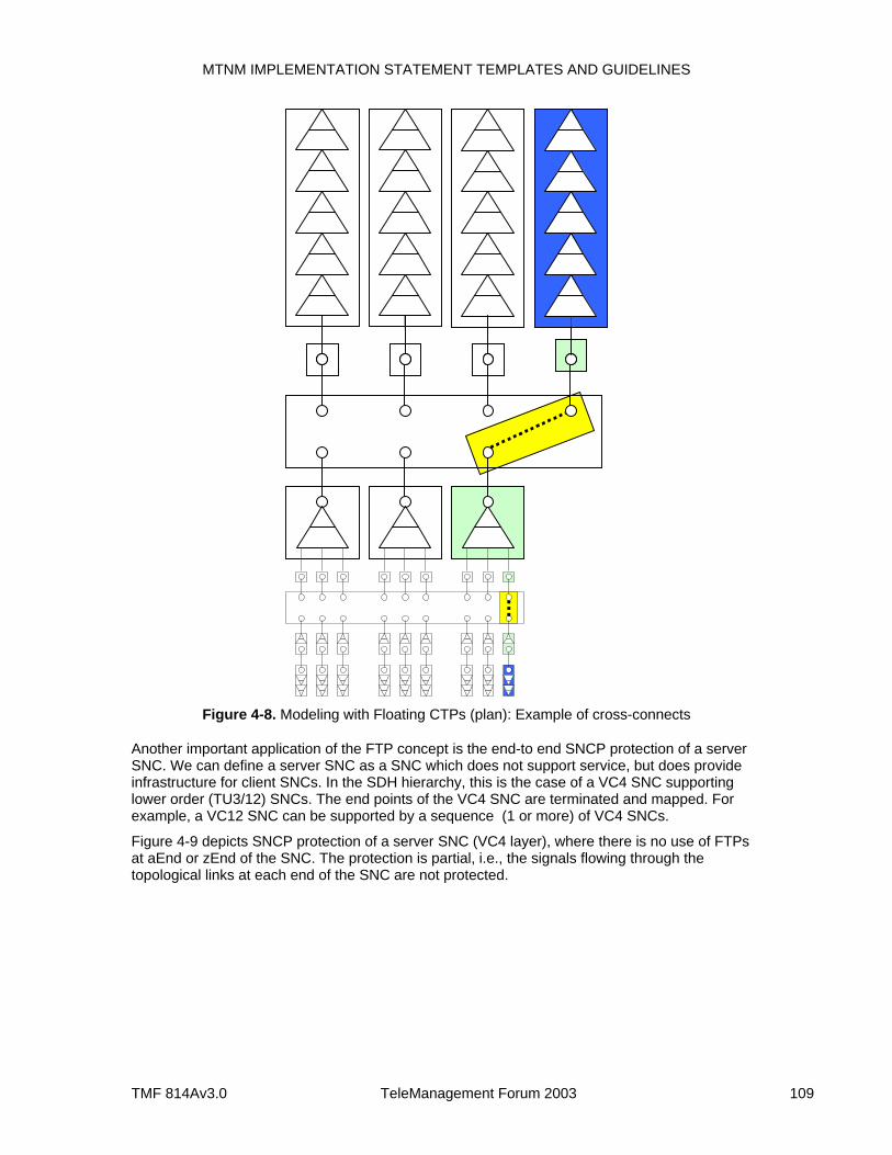
MTNM IMPLEMENTATION STATEMENT TEMPLATES AND GUIDELINES
TMF 814Av3.0 TeleManagement Forum 2003 109
Figure 4-8. Modeling with Floating CTPs (plan): Example of cross-connects
Another important application of the FTP concept is the end-to end SNCP protection of a server SNC. We can define a server SNC as a SNC which does not support service, but does provide infrastructure for client SNCs. In the SDH hierarchy, this is the case of a VC4 SNC supporting lower order (TU3/12) SNCs. The end points of the VC4 SNC are terminated and mapped. For example, a VC12 SNC can be supported by a sequence (1 or more) of VC4 SNCs.
Figure 4-9 depicts SNCP protection of a server SNC (VC4 layer), where there is no use of FTPs at aEnd or zEnd of the SNC. The protection is partial, i.e., the signals flowing through the topological links at each end of the SNC are not protected.
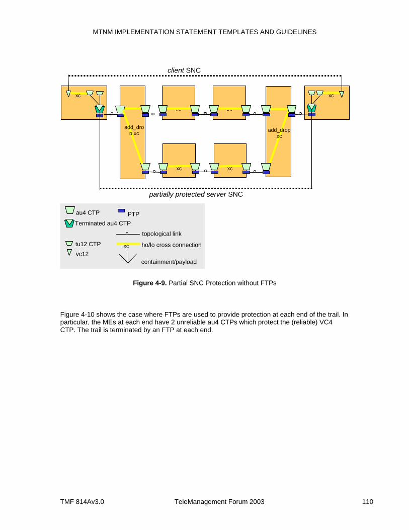
MTNM IMPLEMENTATION STATEMENT TEMPLATES AND GUIDELINES
TMF 814Av3.0 TeleManagement Forum 2003 110
Figure 4-9. Partial SNC Protection without FTPs
Figure 4-10 shows the case where FTPs are used to provide protection at each end of the trail. In particular, the MEs at each end have 2 unreliable au4 CTPs which protect the (reliable) VC4 CTP. The trail is terminated by an FTP at each end.
xc xc
client SNC
xc xc
xc xc
partially protected server SNC
vc12
au4 CTP
tu12 CTP
Terminated au4 CTP
topological link
ho/lo cross connection
containment/payload
PTP
xc
add_drop xc add_drop
xc
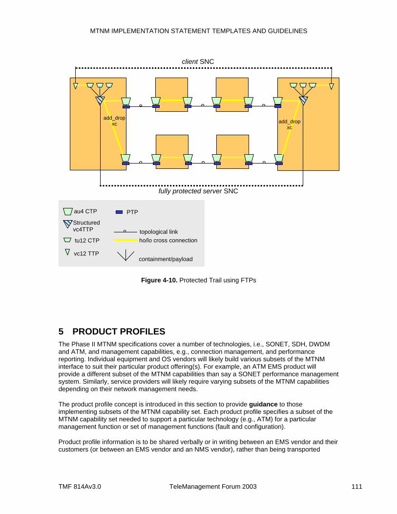
MTNM IMPLEMENTATION STATEMENT TEMPLATES AND GUIDELINES
TMF 814Av3.0 TeleManagement Forum 2003 111
Figure 4-10. Protected Trail using FTPs
5 PRODUCT PROFILES The Phase II MTNM specifications cover a number of technologies, i.e., SONET, SDH, DWDM and ATM, and management capabilities, e.g., connection management, and performance reporting. Individual equipment and OS vendors will likely build various subsets of the MTNM interface to suit their particular product offering(s). For example, an ATM EMS product will provide a different subset of the MTNM capabilities than say a SONET performance management system. Similarly, service providers will likely require varying subsets of the MTNM capabilities depending on their network management needs.
The product profile concept is introduced in this section to provide guidance to those implementing subsets of the MTNM capability set. Each product profile specifies a subset of the MTNM capability set needed to support a particular technology (e.g., ATM) for a particular management function or set of management functions (fault and configuration).
Product profile information is to be shared verbally or in writing between an EMS vendor and their customers (or between an EMS vendor and an NMS vendor), rather than being transported
fully protected server SNC
client SNC
vc12 TTP
au4 CTP
tu12 CTP
Structured vc4TTP topological link
ho/lo cross connection
containment/payload
PTP
add_drop xc add_drop
xc
MTNM IMPLEMENTATION STATEMENT TEMPLATES AND GUIDELINES
TMF 814Av3.0 TeleManagement Forum 2003 112
across the MTNM interface. The profiles themselves apply to the functionality offered by the EMS. An EMS could support more than one product profile.
In this section only a partial list of the set possible product profiles is provided. The product profiles list here are only example are not meant to be prescriptive.
The following product categories are defined in the following subsections.
SONET/SDH Fault-Configuration Manager ATM Fault-Configuration Manager DWDM Fault-Configuration Manager SONET/SDH Performance Manager (statistics collector) SONET/SDH Configuration Manager ATM Configuration Manager DWDM Configuration Manager.
The following format is used to describe the minimum capability set attributed to each product category:
Product Category: e.g., SONET/SDH Fault-Configuration Manager
Supported Managers: e.g., emsManager, emsSession, session, emsSessionFactory, managedElementManager, multiLayerSubnetworkManager, trafficDescriptorManager, performanceManager, protectionManager, equipmentInventoryManager, maintenanceManager, guiCutThroughManager
Supported Operations (on a per manager basis) Supported Notifications (on a per manager basis) Other statements related to interoperability (such statements would typically qualify the
support operations)
Supported Notifications: a list of the notifications for the product category.
In what follows, Mandatory Operations are operations that do not offer the EXCPT_NOT_IMPLEMENTED exception (as defined in the IDL Solution Set). Any deviation from this convention is explicitly noted.
It is assumed that all products based on the MTNM interface supported the mandatory operation(s) of the Common module.
5.1 SONET/SDH Fault-Configuration Manager Product Category: SONET/SDH Fault-Configuration Manager
Supported Managers: emsManager, emsSession, emsSessionFactory, equipmentInventoryManager, guiCutThroughManager, maintenanceManager, managedElementManager, mtnmVersion, multiLayerSubnetworkManager, protectionManager, session
In the following list, all operations marked with a red asterisk (*) have layerRate as a parameter. In the case of the SONET/SDH Fault-Configuration Manager, only the SONET/SDH layerRates need to be supported.
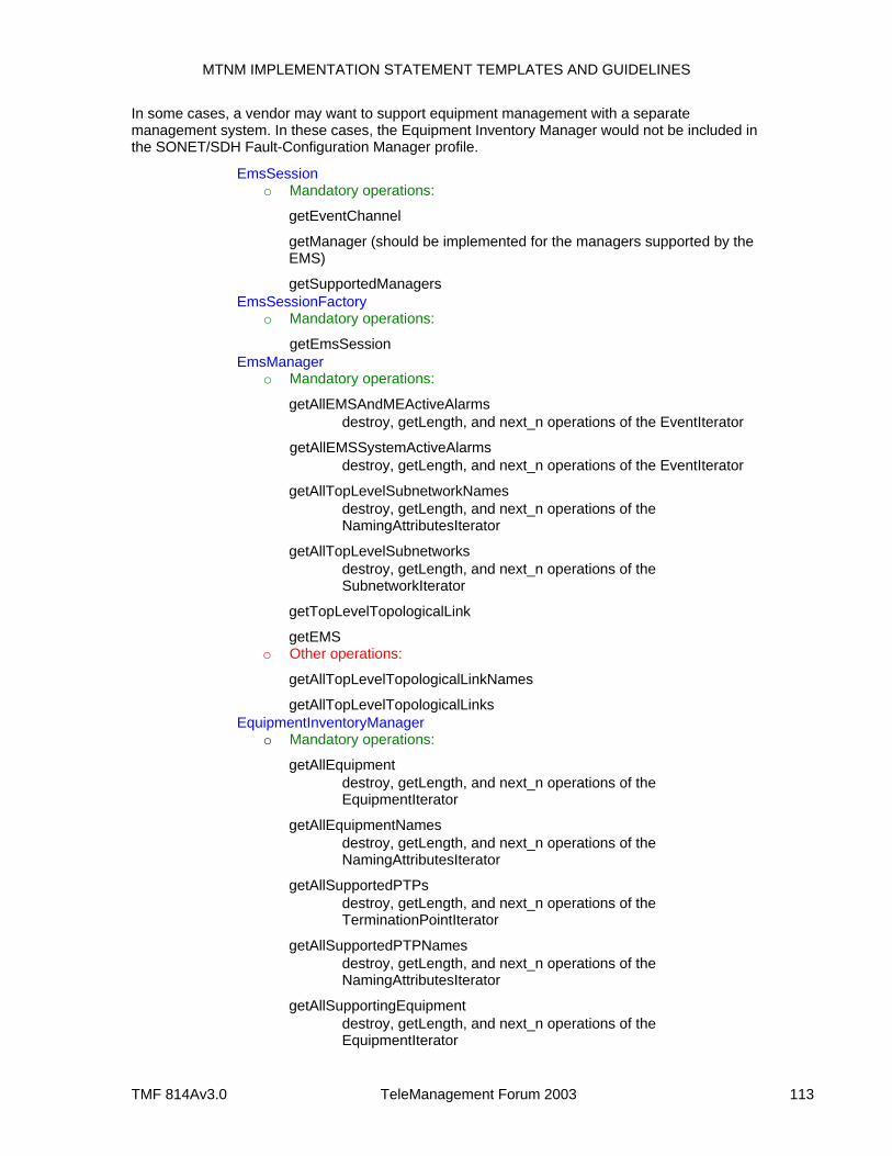
MTNM IMPLEMENTATION STATEMENT TEMPLATES AND GUIDELINES
TMF 814Av3.0 TeleManagement Forum 2003 113
In some cases, a vendor may want to support equipment management with a separate management system. In these cases, the Equipment Inventory Manager would not be included in the SONET/SDH Fault-Configuration Manager profile.
EmsSession o Mandatory operations:
getEventChannel
getManager (should be implemented for the managers supported by the EMS)
getSupportedManagers EmsSessionFactory
o Mandatory operations:
getEmsSession EmsManager
o Mandatory operations:
getAllEMSAndMEActiveAlarms destroy, getLength, and next_n operations of the EventIterator
getAllEMSSystemActiveAlarms destroy, getLength, and next_n operations of the EventIterator
getAllTopLevelSubnetworkNames destroy, getLength, and next_n operations of the
NamingAttributesIterator
getAllTopLevelSubnetworks destroy, getLength, and next_n operations of the
SubnetworkIterator
getTopLevelTopologicalLink
getEMS o Other operations:
getAllTopLevelTopologicalLinkNames
getAllTopLevelTopologicalLinks EquipmentInventoryManager
o Mandatory operations:
getAllEquipment destroy, getLength, and next_n operations of the
EquipmentIterator
getAllEquipmentNames destroy, getLength, and next_n operations of the
NamingAttributesIterator
getAllSupportedPTPs destroy, getLength, and next_n operations of the
TerminationPointIterator
getAllSupportedPTPNames destroy, getLength, and next_n operations of the
NamingAttributesIterator
getAllSupportingEquipment destroy, getLength, and next_n operations of the
EquipmentIterator
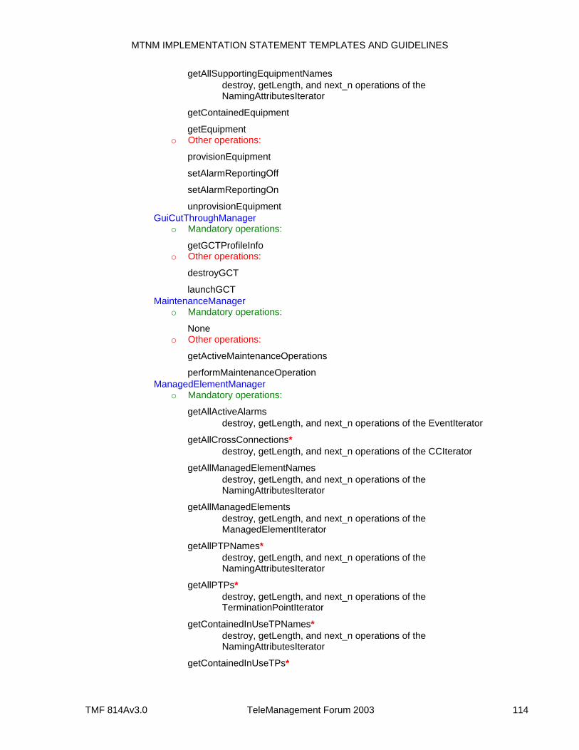
MTNM IMPLEMENTATION STATEMENT TEMPLATES AND GUIDELINES
TMF 814Av3.0 TeleManagement Forum 2003 114
getAllSupportingEquipmentNames destroy, getLength, and next_n operations of the
NamingAttributesIterator
getContainedEquipment
getEquipment o Other operations:
provisionEquipment
setAlarmReportingOff
setAlarmReportingOn
unprovisionEquipment GuiCutThroughManager
o Mandatory operations:
getGCTProfileInfo o Other operations:
destroyGCT
launchGCT MaintenanceManager
o Mandatory operations:
None o Other operations:
getActiveMaintenanceOperations
performMaintenanceOperation ManagedElementManager
o Mandatory operations:
getAllActiveAlarms destroy, getLength, and next_n operations of the EventIterator
getAllCrossConnections* destroy, getLength, and next_n operations of the CCIterator
getAllManagedElementNames destroy, getLength, and next_n operations of the
NamingAttributesIterator
getAllManagedElements destroy, getLength, and next_n operations of the
ManagedElementIterator
getAllPTPNames* destroy, getLength, and next_n operations of the
NamingAttributesIterator
getAllPTPs* destroy, getLength, and next_n operations of the
TerminationPointIterator
getContainedInUseTPNames* destroy, getLength, and next_n operations of the
NamingAttributesIterator
getContainedInUseTPs*
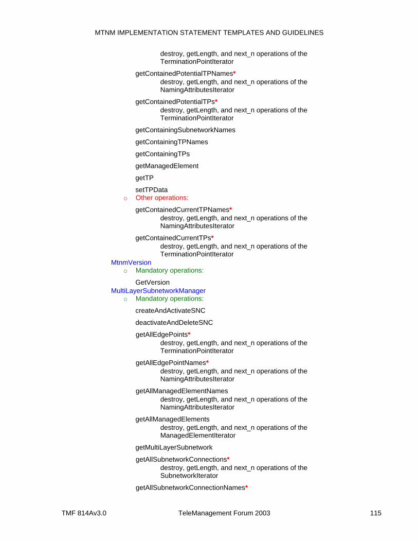
MTNM IMPLEMENTATION STATEMENT TEMPLATES AND GUIDELINES
TMF 814Av3.0 TeleManagement Forum 2003 115
destroy, getLength, and next_n operations of the TerminationPointIterator
getContainedPotentialTPNames* destroy, getLength, and next_n operations of the
NamingAttributesIterator
getContainedPotentialTPs* destroy, getLength, and next_n operations of the
TerminationPointIterator
getContainingSubnetworkNames
getContainingTPNames
getContainingTPs
getManagedElement
getTP
setTPData o Other operations:
getContainedCurrentTPNames* destroy, getLength, and next_n operations of the
NamingAttributesIterator
getContainedCurrentTPs* destroy, getLength, and next_n operations of the
TerminationPointIterator MtnmVersion
o Mandatory operations:
GetVersion MultiLayerSubnetworkManager
o Mandatory operations:
createAndActivateSNC
deactivateAndDeleteSNC
getAllEdgePoints* destroy, getLength, and next_n operations of the
TerminationPointIterator
getAllEdgePointNames* destroy, getLength, and next_n operations of the
NamingAttributesIterator
getAllManagedElementNames destroy, getLength, and next_n operations of the
NamingAttributesIterator
getAllManagedElements destroy, getLength, and next_n operations of the
ManagedElementIterator
getMultiLayerSubnetwork
getAllSubnetworkConnections* destroy, getLength, and next_n operations of the
SubnetworkIterator
getAllSubnetworkConnectionNames*
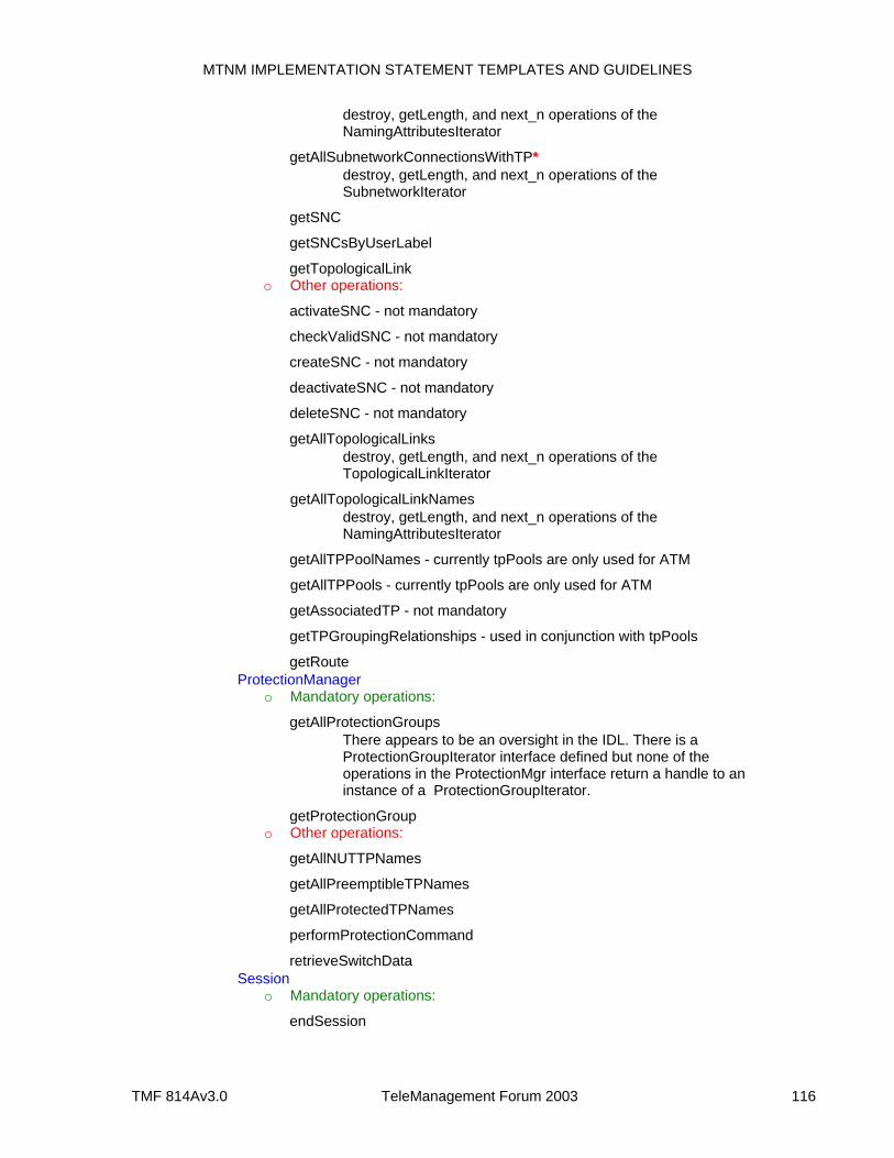
MTNM IMPLEMENTATION STATEMENT TEMPLATES AND GUIDELINES
TMF 814Av3.0 TeleManagement Forum 2003 116
destroy, getLength, and next_n operations of the NamingAttributesIterator
getAllSubnetworkConnectionsWithTP* destroy, getLength, and next_n operations of the
SubnetworkIterator
getSNC
getSNCsByUserLabel
getTopologicalLink o Other operations:
activateSNC - not mandatory
checkValidSNC - not mandatory
createSNC - not mandatory
deactivateSNC - not mandatory
deleteSNC - not mandatory
getAllTopologicalLinks destroy, getLength, and next_n operations of the
TopologicalLinkIterator
getAllTopologicalLinkNames destroy, getLength, and next_n operations of the
NamingAttributesIterator
getAllTPPoolNames - currently tpPools are only used for ATM
getAllTPPools - currently tpPools are only used for ATM
getAssociatedTP - not mandatory
getTPGroupingRelationships - used in conjunction with tpPools
getRoute ProtectionManager
o Mandatory operations:
getAllProtectionGroups There appears to be an oversight in the IDL. There is a
ProtectionGroupIterator interface defined but none of the operations in the ProtectionMgr interface return a handle to an instance of a ProtectionGroupIterator.
getProtectionGroup o Other operations:
getAllNUTTPNames
getAllPreemptibleTPNames
getAllProtectedTPNames
performProtectionCommand
retrieveSwitchData Session
o Mandatory operations:
endSession
MTNM IMPLEMENTATION STATEMENT TEMPLATES AND GUIDELINES
TMF 814Av3.0 TeleManagement Forum 2003 117
ping
getAssociatedSession Supported Notifications:
Mandatory notifications: o Attribute Value Changes (AVC) for Topological Link, Equipment,
Equipment Holder, Subnetwork, PTP, CTP, Subnetwork Connection, Managed Element, Protection Group, EMS
o Object Creation Notifications (OCNs) and Object Deletion Notifications (ODNs) for ManagedElements, Topological Links, Subnetworks, PTPs, and SNCs
o State Change Notifications (SCNs) for Equipment Holder, Equipment, PTP, CTP, Subnetwork Connection, Managed Element, Protection Group
Other notifications: o MTNM team has agreed on formats for alarms but there is no agreement
as to a specific alarm set.
5.2 ATM Fault-Configuration Manager Product Category: ATM Fault-Configuration Manager
Supported Managers: emsManager, emsSession, emsSessionFactory, equipmentInventoryManager, guiCutThroughManager, maintenanceMgr, managedElementManager, mtnmVersion, multiLayerSubnetworkManager, session, trafficDescriptorMgr
Notes:
In the following list, all operations marked with an asterisk have layerRate as a parameter. In the case of the ATM Fault-Configuration Manager, only the ATM layerRates need to be supported.
The protectionMgr interface was mainly designed for SONET/SDH. Consequently, it is left out of the ATM product profile.
EmsSession
For further details, see the EmsSession template in the SONET/SDH Fault-Configuration Manager product profile.
EmsSessionFactory
For further details, see the EmsSessionFactory template in the SONET/SDH Fault-Configuration Manager product profile.
EmsManager
For further details, see the EmsManager template in the SONET/SDH Fault-Configuration Manager product profile.
EquipmentInventoryManager
For further details, see the EquipmentInventoryManager template in the SONET/SDH Fault-Configuration Manager product profile.
GuiCutThroughManager
For further details, see the GuiCutThroughManager template in the SONET/SDH Fault-Configuration Manager product profile.
MaintenanceManager For further details, see the MaintenanceManager template in the SONET/SDH Fault-Configuration Manager product profile. Of the maintenance operations currently supported in the MTNM IDL, only SET_AS_SEGMENT_END_POINT,
MTNM IMPLEMENTATION STATEMENT TEMPLATES AND GUIDELINES
TMF 814Av3.0 TeleManagement Forum 2003 118
END_TO_END_LOOPBACK_OAM_CELL, and SEGMENT_LOOPBACK_OAM_CELL apply to ATM.
ManagedElementManager
For further details, see the ManagedElementManager template in the SONET/SDH Fault-Configuration Manager product profile.
MtnmVersion
For further details, see the Mtnm Version template in the SONET/SDH Fault-Configuration Manager product profile.
MultiLayerSubnetworkManager
Same requirements as those attributed to MultiLayerSubnetworkManager in the SONET/SDH Fault-Configuration Manager product profile except that the getAllTPPoolNames and getAllTPPools operations are mandatory.
Session
For further details, see the Session template in the SONET/SDH Fault-Configuration Manager product profile.
TrafficDescriptorManager o Mandatory operations:
getAllTrafficDescriptorNames destroy, getLength, and next_n operations of the
NamingAttributesIterator
getAllTrafficDescriptors destroy, getLength, and next_n operations of the
TrafficDescriptorIterator
getAssociatedCTPs
getTrafficDescriptor o Other operations:
createTrafficDescriptor
deleteTrafficDescriptor Supported Notifications:
Mandatory notifications: o Attribute Value Changes (AVC) for Topological Link, Equipment,
Equipment Holder, Subnetwork, Traffic Descriptor, PTP, CTP, TP Pool, Subnetwork Connection, Managed Element, EMS
o Object Creation Notifications (OCNs) and Object Deletion Notifications (ODNs) for Topological Link, Equipment, Equipment Holder, Subnetwork, Traffic Descriptor, PTP, TP Pool, Subnetwork Connection, Managed Element
o State Change Notifications (SCNs) for Equipment Holder, Equipment, PTP, CTP, Subnetwork Connection, Managed Element
Other notifications: o MTNM team has agreed on formats for alarms but there is no agreement
as to a specific alarm set.
5.3 DWDM Fault-Configuration Manager Product Category: DWDM Fault-Configuration Manager
MTNM IMPLEMENTATION STATEMENT TEMPLATES AND GUIDELINES
TMF 814Av3.0 TeleManagement Forum 2003 119
Supported Managers: emsManager, emsSession, emsSessionFactory, equipmentInventoryManager, guiCutThroughManager, managedElementManager, mtnmVersion, multiLayerSubnetworkManager, session
Notes:
In the following list, all operations marked with an asterisk have layerRate as a parameter. In the case of the DWDM Fault-Configuration Manager, only the DWDM layerRates need to be supported.
The protectionMgr interface was mainly designed for SONET/SDH. Consequently, it is left out of the DWDM product profile.
The maintenanceMgr interface does not support DWDM maintenance commands and as such is not included in the DWDM product profile.
EmsSession
For further details, see the EmsSession template in the SONET/SDH Fault-Configuration Manager product profile.
EmsSessionFactory
For further details, see the EmsSessionFactory template in the SONET/SDH Fault-Configuration Manager product profile.
EmsManager
For further details, see the EmsManager template in the SONET/SDH Fault-Configuration Manager product profile.
EquipmentInventoryManager
For further details, see the EquipmentInventoryManager template in the SONET/SDH Fault-Configuration Manager product profile.
GuiCutThroughManager
For further details, see the GuiCutThroughManager template in the SONET/SDH Fault-Configuration Manager product profile.
ManagedElementManager
For further details, see the ManagedElementManager template in the SONET/SDH Fault-Configuration Manager product profile.
MtnmVersion
For further details, see the Mtnm Version template in the SONET/SDH Fault-Configuration Manager product profile.
MultiLayerSubnetworkManager
For further details, see the MultiLayerSubnetworkManager template in the SONET/SDH Fault-Configuration Manager product profile.
Session
For further details, see the Session template in the SONET/SDH Fault-Configuration Manager product profile.
Supported Notifications: Mandatory notifications:
o Attribute Value Changes (AVC) for Topological Link, Equipment, Equipment Holder, Subnetwork, PTP, CTP, Subnetwork Connection, Managed Element, EMS
o Object Creation Notifications (OCNs) and Object Deletion Notifications (ODNs) for Topological Link, Equipment, Equipment Holder, Subnetwork, PTP, Subnetwork Connection, Managed Element
o State Change Notifications (SCNs) for Equipment Holder, Equipment, PTP, CTP, Subnetwork Connection, Managed Element
Other notifications:
MTNM IMPLEMENTATION STATEMENT TEMPLATES AND GUIDELINES
TMF 814Av3.0 TeleManagement Forum 2003 120
o MTNM team has agreed on formats for alarms but there is no agreement as to a specific alarm set.
5.4 SONET/SDH Performance Manager Product Category: SONET/SDH Performance Manager
Supported Managers: emsManager, emsSession, emsSessionFactory, mtnmVersion, performanceManagementMgr, session
EmsSession
For further details, see the EmsSession template in the SONET/SDH Fault-Configuration Manager product profile.
EmsSessionFactory
For further details, see the EmsSessionFactory template in the SONET/SDH Fault-Configuration Manager product profile.
MtnmVersion
For further details, see the Mtnm Version template in the SONET/SDH Fault-Configuration Manager product profile.
PerformanceManagementMgr o Mandatory operations:
disablePMData
enablePMData
getAllCurrentPMData This operation is not listed mandatory in the IDL, but is essential
if a product is to offer a PM service. Also need to support the destroy, getLength, and next_n
operations of the PMDataIterator interface
getHistoryPMData This operation is not listed mandatory in the IDL, but is essential
if a product is to offer a PM service.
getMEPMcapabilities
getTCATPParameter
setTCATPParameter This operation is not listed mandatory in the IDL, but is essential
if a product is to offer a PM service. o Other operations:
disableTCA
enableTCA
getHoldingTime Session
For further details, see the Session template in the SONET/SDH Fault-Configuration Manager product profile.
Supported Notifications: Mandatory notifications:
o None Other notifications:
o None
MTNM IMPLEMENTATION STATEMENT TEMPLATES AND GUIDELINES
TMF 814Av3.0 TeleManagement Forum 2003 121
5.5 SONET/SDH Configuration Manager Product Category: SONET/SDH Configuration Manager (This is a subset of the SONET/SDH Fault-Configuration Manager product profile. Items covered in the Fault-Configuration Manager but not in the Configuration Manager are shown as strikethrough.)
Supported Managers: emsManager, emsSession, emsSessionFactory, equipmentInventoryManager, guiCutThroughManager, maintenanceManager, managedElementManager, mtnmVersion, multiLayerSubnetworkManager, protectionManager, session
EmsSession
For further details, see the EmsSession template in the SONET/SDH Fault-Configuration Manager product profile.
EmsSessionFactory
For further details, see the EmsSessionFactory template in the SONET/SDH Fault-Configuration Manager product profile.
EmsManager
The requirements for the EmsManager are the same as those attributed to the EmsManager in the SONET/SDH Fault-Configuration Manager description, except that the getAllEMSAndMEActiveAlarms and getAllEMSSystemActiveAlarms operations should not be supported.
EquipmentInventoryManager
For further details, see the EquipmentInventoryManager template in the SONET/SDH Fault-Configuration Manager product profile.
GuiCutThroughManager
For further details, see the GuiCutThroughManager template in the SONET/SDH Fault-Configuration Manager product profile.
MaintenanceManager
For further details, see the Maintenance Manager template in the SONET/SDH Fault-Configuration Manager product profile.
ManagedElementManager
For further details, see the ManagedElementManager template in the SONET/SDH Fault-Configuration Manager product profile. There is one exception, however, the getAllActiveAlarms operation should not be supported.
MtnmVersion
For further details, see the Mtnm Version template in the SONET/SDH Fault-Configuration Manager product profile.
MultiLayerSubnetworkManager
For further details, see the MultiLayerSubnetworkManager template in the SONET/SDH Fault-Configuration Manager product profile.
ProtectionManager
For further details, see the ProtectionManager template in the SONET/SDH Fault-Configuration Manager product profile.
Session
For further details, see the Session template in the SONET/SDH Fault-Configuration Manager product profile.
Supported Notifications: Mandatory notifications:
MTNM IMPLEMENTATION STATEMENT TEMPLATES AND GUIDELINES
TMF 814Av3.0 TeleManagement Forum 2003 122
o Attribute Value Changes (AVC) for Topological Link, Equipment, Equipment Holder, Subnetwork, PTP, CTP, Subnetwork Connection, Managed Element, Protection Group, EMS
o Object Creation Notifications (OCNs) and Object Deletion Notifications (ODNs) for Topological Link, Equipment, Equipment Holder, Subnetwork, PTP, Subnetwork Connection, Managed Element, Protection Group
o State Change Notifications (SCNs) for Equipment Holder, Equipment, PTP, CTP, Subnetwork Connection, Managed Element, Protection Group
Other notifications: o MTNM team has agreed on formats for alarms but there is no agreement
as to a specific alarm set.
MTNM IMPLEMENTATION STATEMENT TEMPLATES AND GUIDELINES
TMF 814Av3.0 TeleManagement Forum 2003 123
5.6 ATM Configuration Manager Product Category: ATM Configuration Manager (This is a subset of the ATM Fault-Configuration Manager product profile. Items covered in the Fault-Configuration Manager but not in the Configuration Manager are shown as strikethrough.)
Supported Managers: emsManager, emsSession, emsSessionFactory, guiCutThroughManager, maintenanceMgr, managedElementManager, mtnmVersion, multiLayerSubnetworkManager, equipmentInventoryManager, session
Notes:
In the following list, all operations marked with an asterisk have layerRate as a parameter. In the case of the ATM Configuration Manager, only the ATM layerRates need to be supported.
The protectionMgr interface was mainly designed for SONET/SDH. Consequently, it is left out of the ATM product profile.
EmsSession
For further details, see the EmsSession template in the SONET/SDH Fault-Configuration Manager product profile.
EmsSessionFactory
For further details, see the EmsSessionFactory template in the SONET/SDH Fault-Configuration Manager product profile.
EmsManager
The requirements for the EmsManager are the same as those attributed to the EmsManager in the SONET/SDH Fault-Configuration Manager description, except that the getAllEMSAndMEActiveAlarms and getAllEMSSystemActiveAlarms operations should not be supported.
EquipmentInventoryManager
For further details, see the EquipmentInventoryManager template in the SONET/SDH Fault-Configuration Manager product profile.
MaintenanceManager
For further details, see the MaintenanceManager template in the SONET/SDH Fault-Configuration Manager product profile. Of the maintenance operations currently supported in the MTNM IDL, only SET_AS_SEGMENT_END_POINT, END_TO_END_LOOPBACK_OAM_CELL, and SEGMENT_LOOPBACK_OAM_CELL apply to ATM.
ManagedElementManager
For further details, see the ManagedElementManager template in the SONET/SDH Fault-Configuration Manager product profile. There is one exception, however, the getAllActiveAlarms operation should not be supported.
MtnmVersion
For further details, see the Mtnm Version template in the SONET/SDH Fault-Configuration Manager product profile.
MultiLayerSubnetworkManager
Same requirements as those attributed to MultiLayerSubnetworkManager in the SONET/SDH Fault-Configuration Manager product profile except that the getAllTPPoolNames and getAllTPPools operations are mandatory.
Session
MTNM IMPLEMENTATION STATEMENT TEMPLATES AND GUIDELINES
TMF 814Av3.0 TeleManagement Forum 2003 124
For further details, see the Session template in the SONET/SDH Fault-Configuration Manager product profile.
Supported Notifications: Mandatory notifications:
o Attribute Value Changes (AVC) Topological Link, Equipment, Equipment Holder, Subnetwork, Traffic Descriptor, PTP, CTP, TP Pool, Subnetwork Connection, Managed Element, Protection Group, EMS
o Object Creation Notifications (OCNs) and Object Deletion Notifications (ODNs) for Topological Link, Equipment, Equipment Holder, Subnetwork, Traffic Descriptor, PTP, TP Pool, Subnetwork Connection, Managed Element
o State Change Notifications (SCNs) for Equipment Holder, Equipment, PTP, CTP, Subnetwork Connection, Managed Element
Other notifications: o MTNM team has agreed on formats for alarms but there is no agreement
as to a specific alarm set.
5.7 DWDM Configuration Manager Product Category: DWDM Configuration Manager (This is a subset of the DWDM Fault-Configuration Manager product profile. Items covered in the Fault-Configuration Manager but not in the Configuration Manager are shown as strikethrough.)
Supported Managers: emsManager, emsSession, emsSessionFactory, equipmentInventoryManager, guiCutThroughManager, managedElementManager, mtnmVersion, multiLayerSubnetworkManager, session
Notes:
In the following list, all operations marked with an asterisk have layerRate as a parameter. In the case of the DWDM Fault-Configuration Manager, only the DWDM layerRates need to be supported.
The protectionMgr interface was mainly designed for SONET/SDH. Consequently, it is left out of the DWDM product profile.
The maintenanceMgr interface does not support DWDM maintenance commands and as such is not included in the DWDM product profile.
EmsSession
For further details, see the EmsSession template in the SONET/SDH Fault-Configuration Manager product profile.
EmsSessionFactory
For further details, see the EmsSessionFactory template in the SONET/SDH Fault-Configuration Manager product profile.
EmsManager
The requirements for the EmsManager are the same as those attributed to the EmsManager in the SONET/SDH Fault-Configuration Manager description, except that the getAllEMSAndMEActiveAlarms and getAllEMSSystemActiveAlarms operations should not be supported.
EquipmentInventoryManager
For further details, see the EquipmentInventoryManager template in the SONET/SDH Fault-Configuration Manager product profile.
GuiCutThroughManager
For further details, see the GuiCutThroughManager template in the SONET/SDH Fault-Configuration Manager product profile.
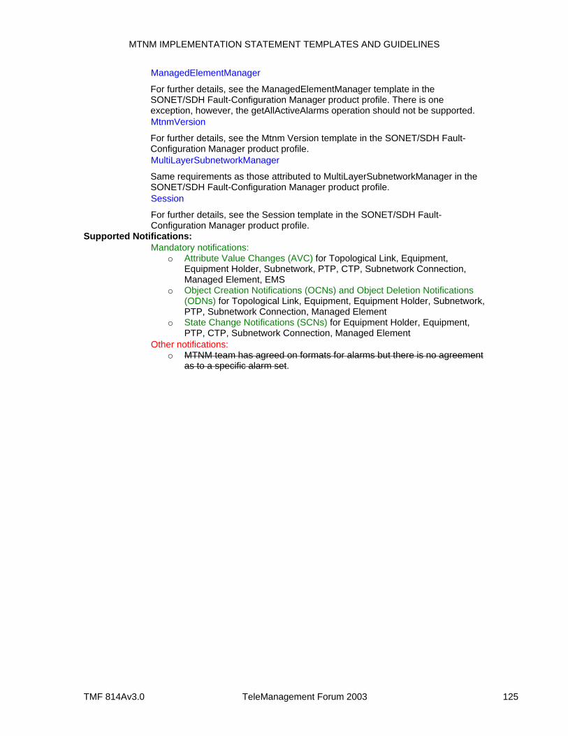
MTNM IMPLEMENTATION STATEMENT TEMPLATES AND GUIDELINES
TMF 814Av3.0 TeleManagement Forum 2003 125
ManagedElementManager
For further details, see the ManagedElementManager template in the SONET/SDH Fault-Configuration Manager product profile. There is one exception, however, the getAllActiveAlarms operation should not be supported.
MtnmVersion
For further details, see the Mtnm Version template in the SONET/SDH Fault-Configuration Manager product profile.
MultiLayerSubnetworkManager
Same requirements as those attributed to MultiLayerSubnetworkManager in the SONET/SDH Fault-Configuration Manager product profile.
Session
For further details, see the Session template in the SONET/SDH Fault-Configuration Manager product profile.
Supported Notifications: Mandatory notifications:
o Attribute Value Changes (AVC) for Topological Link, Equipment, Equipment Holder, Subnetwork, PTP, CTP, Subnetwork Connection, Managed Element, EMS
o Object Creation Notifications (OCNs) and Object Deletion Notifications (ODNs) for Topological Link, Equipment, Equipment Holder, Subnetwork, PTP, Subnetwork Connection, Managed Element
o State Change Notifications (SCNs) for Equipment Holder, Equipment, PTP, CTP, Subnetwork Connection, Managed Element
Other notifications: o MTNM team has agreed on formats for alarms but there is no agreement
as to a specific alarm set.
MTNM IMPLEMENTATION STATEMENT TEMPLATES AND GUIDELINES
TMF 814Av3.0 TeleManagement Forum 2003 126
6 FEATURE MATRIX A prose description of all the MTNM features can be found in the supporting document entitled FeatureSummaryVersion3. A feature support matrix is provided in the featureMatrix supporting document (v2.1 features are listed in the first sheet of the spreadsheet and v3.0 features are listed in the second sheet of the spreadsheet). For each feature, the following information is supplied:
Feature Name – the name of the feature
Operations – a description of new operations or operation modifications needed in support of the feature
Information Classes – a description of new information classes or operation modifications needed in support of the feature
Comments – explanatory test, as needed
Behavior – a description of any new behavior associated with the feature
Notifications – a description of new notifications or notification modifications needed in support of the feature
Feature Dependencies – a listing of other features that need to be supported in order for this feature to work correctly.

MTNM IMPLEMENTATION STATEMENT TEMPLATES AND GUIDELINES
TMF 814Av3.0 TeleManagement Forum 2003 127
REFERENCES
[R1] TM Forum 513 Version 3.0, TM Forum Business Agreement: NML-EML Interface for the Management of Multi-Technology Transport Networks, 2004.
[R2] TM Forum 608 Version 3.0, TM Forum Information Agreement: NML-EML Interface for the Management of Multi-Technology Transport Networks, 2004.
[R3] TM Forum 814 Version 3.0, TM Forum Solution Set: NML-EML Interface for the Management of Multi-Technology Transport Networks, 2004.
MTNM IMPLEMENTATION STATEMENT TEMPLATES AND GUIDELINES
TMF 814Av3.0 TeleManagement Forum 2003 128
STANDARDS
[S1] ITU-T Recommendation X.731, State Management Function, 1992.
[S2] ITU-T Recommendation X.733, Alarm Reporting Function, 1992.
[S3] GR-1093-CORE (Telcordia), Generic State Requirements for Network Elements (NEs), Issue 2, June 2000.