Embed Size (px)
Citation preview

MULTI-STAGE COLLECTOR (MSC™) PROOF-OF-CONCEPT PILOT DESIGN AND EVALUATION.
HENRY V. KRIGMONT, QEP Allied Environmental Technologies, Inc. 15182 Bolsa Chica Road, Suite D. Huntington Beach,
CA 92649 USA
LAWRENCE J. MUZIO AND RANDALL A. SMITH Fossil Energy Research Corp. 23342-C South Pointe Dr., Laguna Hills, CA 92653 USA
ABSTRACT The new MSC™ technology provides an optimum combination of single- and two-stage electrostatic precipitation augmented by barrier filtration. This arrangement ensures that essentially all dust is retained within the collector.
The operation of the MSC™ is virtually independent of the collected material’s electrical resistivity. Hence, its application will be especially beneficial when the electrical resistivity of the collected material either exceeds 1011 or is less than 104 Ohm-cm levels.
This paper will present details of the Proof-of-Concept (POC) MSC™ pilot unit design. The initial pilot results have shown collection efficiencies of 99.99% at face velocities (FV) of about 8 ft/min. Up-to-date results of the MSC™ POC pilot evaluation and future development work will be discussed.
INTRODUCTION Devices currently used in industry to remove particulate matter from various process gases include Electrostatic Precipitators (ESPs) and Fabric Filters (FFs). While these devices are widely used, they have a number of shortcomings. The current work addresses these shortcomings through the development of a new concept for particulate removal and control: the Multi-Stage Collector (MSC™). The MSC™ concept is a patented process that entails a unique integration of both electrostatic precipitation and barrier filtration. The MSC™ concept overcomes not only the shortcomings of conventional ESPs and FFs, but is also technically superior to hybrid ESP/FF concepts currently under development. This paper will provide the technical background on why the MSC™ concept is a major technological advance in particulate collection.
To date, (a) two patents had been issued for the MSC™
concept (Krigmont, US Pat. № 6,524,369 and № 6,932,857), (b) CFD modeling had been performed investigating the flow patterns through the MSC™
t
ICESP X – June 2006 Multi Stage Collector (MSC™) Proof-of-Concept Pilot Design & Evaluation
Fig. 1. MSC™ Proof-of-Concept Pilo
device, and (c) a pilot-scale MSC™
1
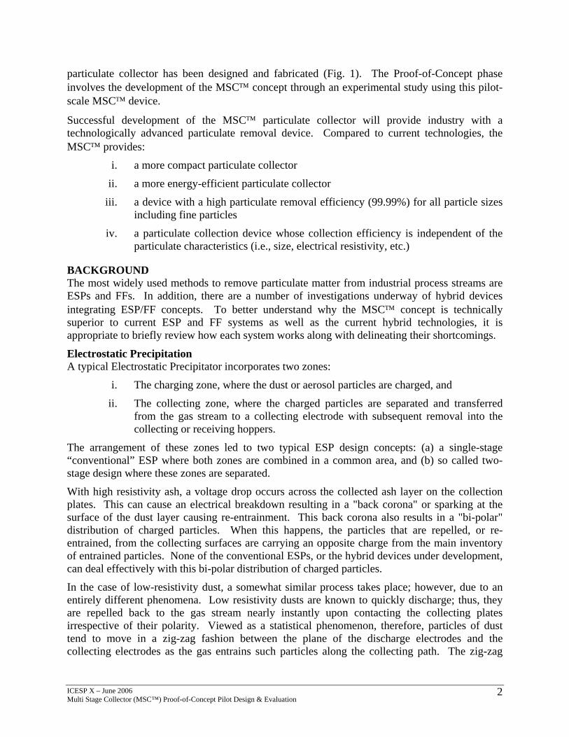
particulate collector has been designed and fabricated (Fig. 1). The Proof-of-Concept phase involves the development of the MSC™ concept through an experimental study using this pilot-scale MSC™ device.
Successful development of the MSC™ particulate collector will provide industry with a technologically advanced particulate removal device. Compared to current technologies, the MSC™ provides:
i. a more compact particulate collector
ii. a more energy-efficient particulate collector
iii. a device with a high particulate removal efficiency (99.99%) for all particle sizes including fine particles
iv. a particulate collection device whose collection efficiency is independent of the particulate characteristics (i.e., size, electrical resistivity, etc.)
BACKGROUND The most widely used methods to remove particulate matter from industrial process streams are ESPs and FFs. In addition, there are a number of investigations underway of hybrid devices integrating ESP/FF concepts. To better understand why the MSC™ concept is technically superior to current ESP and FF systems as well as the current hybrid technologies, it is appropriate to briefly review how each system works along with delineating their shortcomings.
Electrostatic Precipitation A typical Electrostatic Precipitator incorporates two zones:
i. The charging zone, where the dust or aerosol particles are charged, and
ii. The collecting zone, where the charged particles are separated and transferred from the gas stream to a collecting electrode with subsequent removal into the collecting or receiving hoppers.
The arrangement of these zones led to two typical ESP design concepts: (a) a single-stage “conventional” ESP where both zones are combined in a common area, and (b) so called two-stage design where these zones are separated.
With high resistivity ash, a voltage drop occurs across the collected ash layer on the collection plates. This can cause an electrical breakdown resulting in a "back corona" or sparking at the surface of the dust layer causing re-entrainment. This back corona also results in a "bi-polar" distribution of charged particles. When this happens, the particles that are repelled, or re-entrained, from the collecting surfaces are carrying an opposite charge from the main inventory of entrained particles. None of the conventional ESPs, or the hybrid devices under development, can deal effectively with this bi-polar distribution of charged particles.
In the case of low-resistivity dust, a somewhat similar process takes place; however, due to an entirely different phenomena. Low resistivity dusts are known to quickly discharge; thus, they are repelled back to the gas stream nearly instantly upon contacting the collecting plates irrespective of their polarity. Viewed as a statistical phenomenon, therefore, particles of dust tend to move in a zig-zag fashion between the plane of the discharge electrodes and the collecting electrodes as the gas entrains such particles along the collecting path. The zig-zag
ICESP X – June 2006 Multi Stage Collector (MSC™) Proof-of-Concept Pilot Design & Evaluation
2

movement is a phenomenon which is associated with both high- and low-resistance dusts.
Because of the zig-zag phenomenon, the effectiveness of dust collection is reduced, and hence the performance of a dust-collecting or dust-arresting assembly is substantially lower for high- or low-resistance dusts compared to dusts with normal electrical resistivity. The fact that ESP performance depends on the resistivity of the dust is one of the major shortcomings of this device. Fig 2 (Sproull) illustrates the effect of particle resistivity on performance for a conventional ESP. Below a resistivity of 1010 Ohm-cm, but higer than 104 Ohm-cm, the performance of the conventional ESP is generally good. Above 1010 ohm-cm, as well as below 104 Ohm-cm, the performance degrades. Sproull investigated a special two-stage ESP for high resistivity dust collection applications.
His adva
In a 99.9colle1 to
FabElecinduwaysequireplawithFabras colleConlow-gas ahighbaghcentvoluper
ICESPMulti S
Fig. 2. "Conventional" Precipitator Migration Velocity Relationship
laboratory device showed that for high resistivity dust, the two-stage design offers certain ntages, at least based on the reported laboratory data.
conventional configuration, ESPs will have a collection efficiency of nominally 99.5% to %. In addition, this collection efficiency is dependent on particle size. Fig. 3 shows typical ction efficiency versus particle size relationship for an ESP. As can be seen, for sizes below 2 microns (µm), the collection efficiency rapidly degrades.
ric (Barrier) Filters tric power producers, as well as strial-user companies, are looking for to upgrade their particulate control
pment. One approach would be to ce existing under-performing ESPs Fabric Filters (barrier filters). The ic Filters (FFs) are generally accepted an alternative to precipitators for cting fly ash from the flue gas.
ventional designs can be categorized as ratio baghouses (for example, reverse-nd shake-deflate types) and relatively
-ratio ones (so called pulsejet ouses). Low-ratio FFs generally operate at F
imeters per second (1.5 to 2.5 ft/min). FV is alsmetric flow rate of flue gas per unit of effectivesquare foot of filtering area). The high-ratio, p
Col
0
20
40
60
80
100
0 2.5 5 7.5 10 12.5
Particle Diameter, microns
lect
ion
Effic
ienc
y, %
X – June 2006 tage Collector (MSC™) Proof-of-Concept Pilot Design & Evaluation
Fig.3. ESP Collection Efficiency
iltration Velocities (FVs) of 0.76 to 1.27 o defined as air-to-cloth (A/C) ratio, or the filter area (cubic feet of flue gas flow/min ulsejet (PJ) baghouses on the other hand,
3

generally operate at 1.52 to 3.05 centimeters per second (3 to 6 ft/min).
FFs generally have very high collection efficiencies (greater than 99.9%) and the collection efficiency is largely independent of fly ash properties. However, because of their low filtration velocities, they are large, require significant space, costly to build, and unattractive as replacements for existing ESPs. Reducing their size by increasing the filtration velocity across the filter bags usually results in unacceptably high pressure drop and reduced collection efficiency. There is also potential for "blinding" the filter bags – a condition where particles become embedded deep within the filter and cannot be "cleaned” out of the filter material.
A typical PJ baghouse includes a number of individual bags or filtration tubes, each four to six inches in diameter, eight to twenty four feet long, and are mounted within and suspended from a tube sheet. The particulate dust is collected on the outside surface of the bags while the clean flue gas passes through the porous media to the inside, where it exits through the top of the bags into a clean air plenum and subsequently passes out the stack. Cages are installed inside the bags to prevent them from collapsing during the normal filtration process. The bags are cleaned by directing a pulse of compressed air down the center of the inside of the filtration tube.
Because of the small bag spacing of the PJ units and forward filtration through the two rows of bags adjacent to the row being cleaned, much of the dust that is removed from one row of bags during the pulsed-air cleaning is simply recollected on the adjacent rows of bags. Thus, only the very large agglomerates of dust reach the hopper at the bottom of the device. This phenomenon of re-dispersion and collection of dust after bag cleaning is a major obstacle to operating ‘conventional’ baghouses at higher filtration velocities.
Hybrid Particulate Collectors The traditional ESPs suffer from relatively low collection efficiency, particularly for fine particulates, and its performance depends on the electrical resistivity of the particulate that is being collected. While exhibiting a much greater collection efficiency that is largely independent of both particle size and property, the FFs provide a rather large pressure drop and are physically large devices.
In an effort to overcome the above deficiencies (i.e., increasing the collection efficiency without a corresponding increase in pressure drop), a number of efforts have been, and are currently, underway to develop hybrid particle collectors. These hybrid devices attempt to integrate electrostatic and barrier filtration into a single device or system. The MSC™ device, which is the subject of this paper, falls into this hybrid category. That said, it is important to discuss why the MSC™ concept is technically superior to other hybrid concepts.
The hybrid particulate collection concepts of interest include:
i. Electrostatically enhanced Fabric Filter
ii. COHPAC-1 and COHPAC-2 systems
iii. Advanced Hybrid™
iv. MSC™
MSC™ Particulate Collector The principal objective of the MSC™ design is to substantially improve fine particulate collection by combining electrostatic charging-collection and filtration processes not only by
ICESP X – June 2006 Multi Stage Collector (MSC™) Proof-of-Concept Pilot Design & Evaluation
4

separating zones for particle charging and collecting, but by providing a new and unique collector design with improved efficiency for the collection of fine dust particles independent of their electrical properties. Fig. 4 presents an artist’s rendition of the conceptual MSC™
arrangement.
The MSC™ design offers a uniquely compact concept. Each of the multiple stages utilizes an upstream stage comprised of a conventional electrostatic precipitator, followed by a downstream zone of parallel surfaces creating uniform electric field, followed by yet another stage, which incorporates conductive barrier-filter surfaces, which also provide a uniform electric field. By providing continuously repeated stages in series, the downstream zones effectively charge the particles that are either uncollected or re-entrained, and then collect those particles
afte
)
In twodiffDifdiawitine
Oninelowparcol
Thechathecanpotsecplauni
Thesuicoldiswid
ICESMult
Fig. 4. MSC Arrangement (Artist’s Rendition
r they have been charged.
the MSC™, particles are deposited onto the Barrier Filter Element (BFE) predominantly by mechanisms, electrostatic and diffusional deposition, that act simultaneously. Collection by usion occurs because of both fluid motion and the Brownian (random) motion of particles. fusional collection effects are most significant for particles less than 1 micron (µm) in meter. Another collection mechanism, direct interception, occurs when a particle comes hin one particle radius of an obstacle. The path that the particle takes can be a result of rtia, diffusion, or fluid motion.
one hand, electrostatic deposition is effective for relatively large particles, but it is quite ffective for the ultra-fine ones because their charging probability in the corona field is too . However, the diffusional collection efficiency of particles on fibers is high for small ticles but low for the larger ones. Therefore, the simultaneous diffusional-electrostatic lection is a useful technique for efficient filtration of ultra-fine particle sizes below 0.1 µm.
MSC™ design (Fig. 5a) consists of discharge electrodes (DE) placed between oppositely rged collection electrodes (CE). The discharge electrodes are followed by BFEs located in wide zone placed between the collecting electrodes. Additionally, the surface of the BFEs be made electrically conductive. The corrugated collecting plates are held at a first electrical ential while the discharge electrodes and the conductive surface of the BFEs are held at a ond electrical potential. Both the flat sides of each of the discharge electrodes, corrugated tes and the surface of the BFEs form collecting surfaces where the electric field is relatively form.
surfaces of the conductive BFEs are formed with electric field forming parts that may be tably rounded and convex in the direction of the collecting electrode. The corrugated plate lecting electrodes are formed with narrow and wide sections to accommodate both the charge electrodes and BFEs. By using an electrode with a cross-section that is relatively e, a uniform electric field can form in the region of the center of the electrode, and a
P X – June 2006 i Stage Collector (MSC™) Proof-of-Concept Pilot Design & Evaluation
5

non-uniform field of high intensity can form at the sharp curvature of the leading and/or trailing edges.
At sufficiently high field strength in the non-uniform field region, a corona discharge can take place between the discharge electrode and the plates acting as an ion-charging source for dust particles passing through it (Fig. 5b). The center region of uniform field on the other hand acts in a manner similar to the field between parallel capacitor plates with charged dust particles collecting on the plates.
(a) Overall MSC™ Arrangement
(b) Phenomena Occurring in a MSC™
Fig. 5. MSC™ Operating Principals
The dust particles around the discharge electrodes (i.e., in the regions of the corona-generating points), which are charged to negative polarity, are caught by the collecting electrode. Meanwhile, dust particles near the corrugated collecting plate electrode, which have been charged to a positive polarity by the positive ions resulting from reverse ionization, are conveniently collected by the uniform field-forming part of the discharge electrode and the conducting surfaces of the BFEs. Thus, the MSC™ collector can deal with a bi-polar distribution of charged particles.
The spacing between the discharge points (corona sources) and collecting surfaces are different, wider in the charging or corona generating zones and narrower in the collecting ones where a uniform high voltage electric field is required. This feature allows for the use of a single high voltage power source for all electrostatic fields (in all zones). A high voltage electric field of an adjustable (variable) frequency and/or alternating polarity could also be applied to the device to further improve the collecting efficiency of both positively- and negatively-charged particles onto the surfaces of the plates, thereby substantially increasing the effective collecting area. It should also be noted that all collection surfaces can be cleaned in a conventional manner such as by rapping, polarity reversal, or by other means.
Another unique feature is that the MSC™ is engineered in such a way that the BFEs and the discharge electrodes (DEs) are grounded while the parallel-corrugated plates are suspended from the insulators. Consequently, by virtue of having the BFEs at the same potential as the DEs, the MSC™ design completely eliminates any potential sparks from the DEs toward the BFEs, thus eliminating any chance of causing fires and/or puncturing holes in the porous filter media. Hence, whether the MSC™ is powered by a “conventional” or an alternating power source, the
ICESP X – June 2006 Multi Stage Collector (MSC™) Proof-of-Concept Pilot Design & Evaluation
6

BFEs remain protected from any sparks from the DEs irrespective of dust concentration.
As is apparent from the above discussion, the MSC™ design overcomes most of the issues associated with hybrid collectors and should provide a compact, high efficiency, and energy efficient device.
EXPERIMENTAL WORK
Technical Objectives The overall technical objective of the Proof-of-Concept (POC) development phase is to experimentally demonstrate at a small pilot-scale the advantages of the MSC™ concept over conventional particulate collectors (i.e., ESPs, FFs, and other hybrid ESP/FF collectors). Specific questions to be answered during the POC phase include:
i. Does the MSC™ device exhibit higher overall collection efficiency than other hybrid collectors (i.e., collection efficiency >99.9%)?
ii. Is the MSC™ collection efficiency independent of ash resistivity?
iii. Is the MSC™ collection efficiency of fine particles better than conventional technology?
iv. Can the overall size of the MSC™ device (i.e., Face Velocity) be markedly smaller than conventional technology, for a given collection efficiency?
v. Can the MSC™ effectively collect a bipolar distribution of charged particles?
vi. Is the MSC™ device immune to back corona?
Proof of Concept MSC™ Pilot The Proof-of-Concept development phase is being done using a working prototype of the MSC™ (POC MSC™) that was designed to operate with the face velocity (FV) in the 3.59 to 28.73 ft/min (0.02 to 0.15 m/s) range. The POC MSC™ was designed to obtain sufficient data for scale-up of the MSC™ concept.
Design of the equipment was based on computer simulations, engineering calculations, and previous conceptual analyses. Fig. 6 presents a view of the POC MSC™ with the hopper removed. The POC MSC™ consists of two (2) rows of barrier filters (bags) with four (4) bags in each row for a total of eight (8) bags. The two rows of bags are placed between three (3) corrugated collecting plates. The POC MSC™ design data are presented in Table 1. At this scale, it will be possible to satisfy most of the important dimensions such as electrode spacing, BFE diameter, and spacing along each row. The most important dimensions to simulate are the discharge point-to-plate parallel surface spacing in the narrow and wide zones, the discharge point-to-BFE spacing, and the BFE
Fig. 6. View into Bottom of the Pilot MSC Unit
ICESP X – June 2006 Multi Stage Collector (MSC™) Proof-of-Concept Pilot Design & Evaluation
7

diameters, so these dimensions are similar to that of a full-scale unit. This approach simulates the geometric arrangement in a full-scale MSC™ and facilitates testing the effect of cleaning adjacent BFEs. Furthermore, testing at different FVs can easily be accomplished by either removing BFEs or by blocking an entire gas passage. Sight ports are installed at strategic locations to facilitate visual inspection and video monitoring of the BFEs, as well as the discharge and corrugated plate electrodes during normal filtration and cleaning cycles. The POC MSC™ casing will be heat-traced and insulated for precise temperature control.
Table 1. Demonstration MSC™ Design Data
English Metric Temperature Deg. F - C 300.0 148.9Flue Gas Moisture % 8.50 8.50Flue Gas Flow, dry cfm - Nm3/s 33 0.02 Flue Gas Flow, actual acfm - m3/s 60 0.03 Gas Passages per Compartment No. 2 2Barrier Filter Diameter inch - cm 4.00 10.16Barrier Filter Length ft. - m 2.00 0.61No. of BF's per Gas Passage No. 4 4Filtration Velocity (FV) ft/m - m/s 3.59 0.02Electrical Gap in Charging Zone in - mm 1.50 38Electrical Gap in Uniform Field Zone in - mm 1.00 25.40Electrical Gap in Barrier Filter Zone in - mm 1.00 25.40Effective Length of Collecting Electrodes ft. - m 4.26 1.30Number of DE per Gas Passage No. 4 4Effective Height ft. - m 2.00 0.61 Effective Electrode Collecting Area in ESP Zones per Compartment
sq. ft. - m2 39.40 3.66
Total Collecting Area per Compartment sq. ft. - m2 56.16 5.22Total Collecting Area sq. ft. - m2 56.16 5.22
Design Details
Design Inlet Conditions
Barrier Filter Data
ESP Zones Data
UNIT ID === >Simulated Performance Data
250,000 Btu/hr
Combustion Facility The pilot-scale MSC™ unit is set up in Fossil Energy Research Corporation's (FERCo) combustion research laboratory in Laguna Hills, California. FERCo's pilot-scale combustor is used to supply ash-laden flue gas to the MSC™ pilot unit. This facility has been used for a wide variety of studies ranging from fundamental studies of the measurement of N2O in combustion systems and SNCR chemistry, to the characterization of dry SO2 removal processes. A schematic of the overall pilot-scale facility used for these tests is shown in Fig. 7.
The pilot-scale combustor fires natural gas with a Hauck Model 215 burner into a water-cooled combustion section. The gas temperature leaving the burner section is controlled by the firing rate and water-cooled inserts. The air and natural gas flow to the burner and combustion section are controlled with valves and monitored with rotameters. Ash can be pneumatically injected into the combustion section through a water-cooled probe. The ash is metered with a gravimetric screw feeder and pulled into the transport line through an eductor, and the eductor motive air is monitored with a rotameter.
Various other chemicals, such as liquid urea and ammonium hydroxide solutions, can be injected into the combustion products through a single water-cooled injector located in the venturi
ICESP X – June 2006 Multi Stage Collector (MSC™) Proof-of-Concept Pilot Design & Evaluation
8

section, depending on the nature of the study. The venturi section has a three-inch diameter throat, with the exit increasing to match the six-inch diameter test section. Fly ash from selected utility boilers is pneumatically injected into the natural gas combustion products
Fig. 7. Pilot-Scale Apparatus: Combustor, MSC™ and Ancillary Equipment
Particulate Loading Measurements The particulate loading and size distribution entering and leaving the POC MSC™ unit are measured using a Process Metrics laser-based PSCV analyzer (Holve, et. al). Fig. 8 shows a schematic of the setup. The PCSV principle of operation is based on measuring the light scattered by single particles moving through the sample volume of a focused laser beam. The laser beam is brought to a focus midway between the transmitter and receiver tubes of the optics. The particle-sensing region or sample volume is defined by the dimensions of the laser beam at the focus point and by the receiver aperture. Fig. 9 shows a schematic (not to scale) of the sample volume region. Particles may pass anywhere along the length of the laser beam. However, only those particles passing through the sample volume scatter light that is collected by the receiver. The PCSV technique is based on classical, near-forward light scattering techniques, which have been shown to be minimally sensitive to particle shape and refractive index.
As particles pass through the sample volume, light scattered in the near forward direction is collected by the receiver lens and focused onto a fiber optic cable. The fiber optic cable conducts the scattered light pulses from the optics to the detector in the signal processor where the pulses are analyzed.
For each scattered light pulse, the signal processor measures the peak signal intensity (related to particle size), and the signal width (related to particle speed). Since the laser light intensity varies across the measurement volume, a particle trajectory through the center of the measurement volume results in a much higher signal intensity than does a particle trajectory near the boundary. Therefore, the amplitude of the scattered light signal depends not only on the particle size, but also on its trajectory. Once a large number of scattered light signals are collected, the software uses an intensity deconvolution algorithm to determine the absolute particle concentration, particle size distribution, and average particle speed. The intensity
ICESP X – June 2006 Multi Stage Collector (MSC™) Proof-of-Concept Pilot Design & Evaluation
9

deconvolution algorithm is based on the statistical analysis of a large number of individual events, which in this case are the individual scattered light signals from single particles passing through the measurement volume. This analysis has the advantage that no assumptions are required about the shape of the size distribution. This size distribution is obtained directly from the experimental data.
Fig. 8. Schematic of the PCSV Instrument Fig. 9. Schematic of PCSV Sample Volume
In order to cover the wide dynamic range in concentration and size, logarithmic scales are used. Two laser beams are used to span the entire size range. One beam measures the smaller particle sizes, from about 0.3 to 2-3 µm. A second beam measures the larger particle sizes, from about 3 to 100-200 µm. The exact particle size ranges depend on the laser beam focus dimensions and the particle concentration. At higher particle concentrations where the two sizes ranges do not overlap, an interpolation is made between the two size ranges. The total distribution is the combination of two independent measurements using the two laser beam diameters, which differ by a factor of 10. The congruence of these two independent measurements is a significant consistency check for the PCSV.
The lower bound for particle size measurement in each beam for any given particle size distribution is set by the lower discriminator level. The lower discriminator level is in turn dictated by the single particle counting requirement: only one particle at a time passing through the measurement volume.
Computational Fluid Dynamics (CFD) Modeling To verify the gas flow inside the pilot MSC™ device, a Computational Fluid Dynamics (CFD) model was built based on the geometry shown on Fig. 10. The model included MSC™ inlet, filtration bags and internal electrodes. The gas flow properties for the CFD model were based on the data from Table 1. The simulation was based on an ideal gas with air properties, and a two parameter κ-ε turbulence model was employed with smooth wall boundary conditions on MSC™ wall and internal electrodes and barriers.
Approximately 150,000 unstructured-mesh cells were used for the current simulation. The results of the CFD simulations are presented in Fig. 10 and Fig. 11, showing the gas flow
ICESP X – June 2006 Multi Stage Collector (MSC™) Proof-of-Concept Pilot Design & Evaluation
10

distribution in different planes through the device. The simulation results confirmed that gas is distributed relatively evenly among the bags due to the high resistance of the bag cloth to the gas flow. A small gas recirculation zone is observed inside the hopper (Fig. ), but the values of the velocities there are small and probably will not cause any problem. In addition, a recirculation zone is present where the gas entering the MSC™ hits the internal plate.
Fig. 10. CFD Simulation Fig. 11. Gas Recirculation in the Hopper
Demonstration MSC™ Start-Up and Shake-Down Tests The pilot MSC™ device has been setup at the FERCo facility as shown in Fig. 1 and Fig. 7.
V-I Vurves
0
0.5
1
1.5
2
2.5
3
3.5
10 14 15 17 20 22 23 24 25 26 27 28 29 30 31
Voltage, kV
Cur
rent
, mA
Positive, 12-2-04Positive, 18-2-04Negative, before strings trimmingNegative, after strings trimmingNegative (w/o cages)Positive, 18-02-04 (last)
Fig. 12. Demonstration MSC™ Electrical Clearances Evaluation
ICESP X – June 2006 Multi Stage Collector (MSC™) Proof-of-Concept Pilot Design & Evaluation
11

Prior to running the ash-loading tests with the natural gas combustion products, a series of tests were run to characterize the voltage-current (V-I) response of the pilot-scale unit. Two independent high-voltage power supplies with the ability to provide both positive and negative voltage were utilized to charge the corrugated plates. The goals of these shake-down tests were two-fold. The first was to evaluate the electrical clearances in the pilot-scale unit and to identify any plate/electrode/BFE alignment issues that would result in premature sparking. Once any alignment issues were identified and corrected, the V-I response of the unit was fully characterized.
Fig. 12 presents the results of the initial V-I characterization of the pilot MSC™. The initial tests were run in the positive corona mode, and the maximum voltage attainable prior to the onset of sparking was 28 kV. These initial tests were run with the hopper, inlet, and all inspection panels removed so that the areas of sparking could be identified and subsequently addressed. Fig. 13 illustrates the sparking phenomena occurring between a DE and a plate at the voltage-limiting sparking condition. Following optimizing the electrical clearances, the maximum achievable voltage increased to 30 to 31 kV as shown by the positive corona results. Subsequent to optimizing the pilot unit in the positive corona mode, a series of tests was also run where a negative voltage was applied to the plates. As shown in Fig. 12, sparking occurred at much lower voltages in the negative corona mode.
Fig. 13. Sparking at the Top of the Electrode System
Overall, the shake-down tests indicated the V-I performance of the pilot MSC™ to be far better in the positive, rather than negative, corona mode.
Initial MSC™ Collection Efficiency Tests A short series of tests were run to compare the particulate collection efficiency and pressure drop characteristics of the MSC™ concept to that of a conventional pulsejet fabric filter. These tests were run by operating the pilot MSC™ with the electric field energized (MSC™ mode), and un-energized (pulsejet mode). For both sets of tests, the pilot MSC™ was supplied with ambient air at an air-to-cloth ratio of approximately 8.0 (total of six bags in operation). Fly ash obtained from a Powder River Basin (PRB) coal-fired boiler was injected into the air stream ahead of the pilot MSC™ at a loading rate typical of that for a full-scale PRB-fired utility boiler (nominally 2 gr/scf).
In each operating mode (MSC™ and pulsejet), the fabric filter bags were first cleaned down to a pressure drop level of 0.5 to 0.7 inches H2O. Fly ash injection was then initiated, and the PCSV instrument utilized to monitor the outlet mass loadings until the pressure drop reached a level of 8.0 inches H2O.
Fig. 14 illustrates the pressure drop and collection efficiency results for both sets of tests. With the electric field off, the pressure drop increased at a rapid rate, reaching 8.0 inches H2O in less
ICESP X – June 2006 Multi Stage Collector (MSC™) Proof-of-Concept Pilot Design & Evaluation
12

than one hour. The particle collection efficiency with the electric field off improved from 99.71 to 99.81% as the pressure drop increased, but then the efficiency began to decline at the highest differential pressure point.
MSCTM Performance with Electrical Field "ON" and "OFF"(MSCTM vs. Pulse-Jet)
99.70
99.75
99.80
99.85
99.90
99.95
100.00
0:00 0:28 0:57 1:26 1:55 2:24 2:52 3:21 3:50 4:19 4:48
Elapsed Time (hr:min)
Effic
ienc
y, %
0
1
2
3
4
5
6
7
8
9
dP, i
n H
2O
Efficiency - MSCTM
Mode
Efficiency - PulseJet Mode
dP - MSCTM
Mode
dP - PulseJet Mode
Fig. 14. MSC™ POC Pilot Performance
In contrast, with the electric field energized (MSC™ mode), the pressure drop increased at a much slower rate, reaching 8.0 inches H2O in approximately 4.5 hours. Presumably, the improvement was due to the fact that a large fraction of the particulate mass was collected electrostaticly on the plates, rather than on the fabric filter elements. This phenomenon was verified via visual observations made through the view ports installed on the rear wall of the pilot-scale unit (i.e. the wall opposite the dirty-gas inlet). In the pulsejet mode, large quantities of suspended ash particles were clearly visible in the passages between the fabric filter elements, as well as in the hopper area below. Energizing the electric field immediately resulted in a significant reduction in the visible amount of suspended fly ash particles in these areas.
Finally and most importantly, the particle collection efficiency results for the MSC™ mode were markedly higher than those for pulsejet operation, achieving 99.99% across nearly the entire range of pressure drop up to 8.0 inches H2O.
REFERENCES Krigmont, Henry V. “Multi Stage Collector.” US Patent № 6,524,369. February 25, 2003
Krigmont, Henry V. “Multi Stage Collector and Method of Operation.” 6,932,857. August 23, 2005
Sproull, Wayne, T. “Collecting High Resistivity Dusts and Fumes” Industrial and Engineering Chemistry, Vol.47, № 5, May 1955.
White, H. “Industrial Electrostatic Precipitation.” 1963. Reprinted by the International Society
ICESP X – June 2006 Multi Stage Collector (MSC™) Proof-of-Concept Pilot Design & Evaluation
13

for Electrostatic Precipitation.
Chen, Ramsay. “Compact hybrid particulate collector.” US Patent № 5,024,681, 1991.
Chen, Ramsay. “Compact hybrid particulate collector (COHPAC).” US Patent № 5,158,580, 1992
Miller, S., Schelkoph, G, Dunham, G; Walker, K; Krigmont, H. “Advanced Hybrid Particulate Collector, a New Concept for Air Toxics and Fine-Particle Control.” Presented at EPRI-DOR-EPA Combined Utility Air Pollution Control (MEGA) Symposium. Washington, D.C. August 25-29, 1997
Holve, D., Meyer, P., Muzio,L., Shiomoto, G., “On-Line Insitu Particle Measurements in a Large Scale Coal Fired Furnace”, Paper 88-60, Western States Section of the Combustion Institute, Spring Meeting, March 1988, Salt Lake City.
ICESP X – June 2006 Multi Stage Collector (MSC™) Proof-of-Concept Pilot Design & Evaluation
14