Embed Size (px)
Citation preview
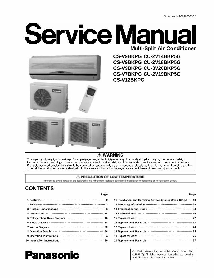
1 Features 2 2 Functions 3 3 Product Specifications 6 4 Dimensions 14 5 Refrigeration Cycle Diagram 16 6 Block Diagram 18 7 Wiring Diagram 22 8 Operation Details 26 9 Operating Instructions 34 10 Installation Instructions 39
© 2002 Matsushita Industrial Corp. Sdn. Bhd.(11969-T). All rights reserved. Unauthorized copyingand distribution is a violation of law.
CS-V9BKPG CU-2V14BKP5GCS-V9BKPG CU-2V18BKP5GCS-V9BKPG CU-3V20BKP5GCS-V7BKPG CU-2V19BKP5GCS-V12BKPG
11 Installation and Servicing Air Conditioner Using R410A 49 12 Servicing Information 60 13 Troubleshooting Guide 64 14 Technical Data 66 15 Exploded View 72 16 Replacement Parts List 73 17 Exploded View 74 18 Replacement Parts List 75 19 Exploded View 76 20 Replacement Parts List 77
Multi-Split Air Conditioner
CONTENTS Page Page
Order No. MAC0205021C2
21 Exploded View 78 22 Replacement Parts List 79 23 Exploded View 80
• High Efficiency
• Compact Design
• Comfort Environment − 8 hours of sleep mode operation − Air filter with function to reduce dust and smoke − Wider range of horizontal discharge air
• Auto Restart − Random auto restart after power failure for safety restart
operation
• Removable and Washable Front Panel
• Remote Control Self-illuminating Button
• Catechin Air Purifying Filter − Trap dust, tobacco smoke and tiny particles − Prevent the growth of bacteria and viruses trapped
• Solar Refreshing Deodorizing Filter − Remove unpleasant odour from the air
24 Replacement Parts List 81 25 Electronic Parts List 82 26 Electronic Circuit Diagram 83
• Quality Improvement − Gas leakage protection − Prevent compressor reverse cycle − 2-stage OLP to protect compressor − Noise prevention during soft dry operation. − Anti-dew Formation Control (Cooling & Soft Dry)
• Operation Improvement − Economy mode to reduce electrical power consumption − Powerful mode to reach the desired room temperature
quickly
• Long Installation Piping − Long piping up to 15 meter
• 24-hour Timer Setting
• Environmental Friendly − R410A, which does not contain chlorine, is used as its
refrigerant, so there is no danger of damage to theozone layer in stratosphere .
1 Features
2
CS-V9BKPG CU-2V14BKP5G / CS-V9BKP G CU-2V18BKP5G / CS-V9BKP G CU-3V20BKP5G / CS-V7BKP G CU-2V19BKP5G / CS-V12BKPG
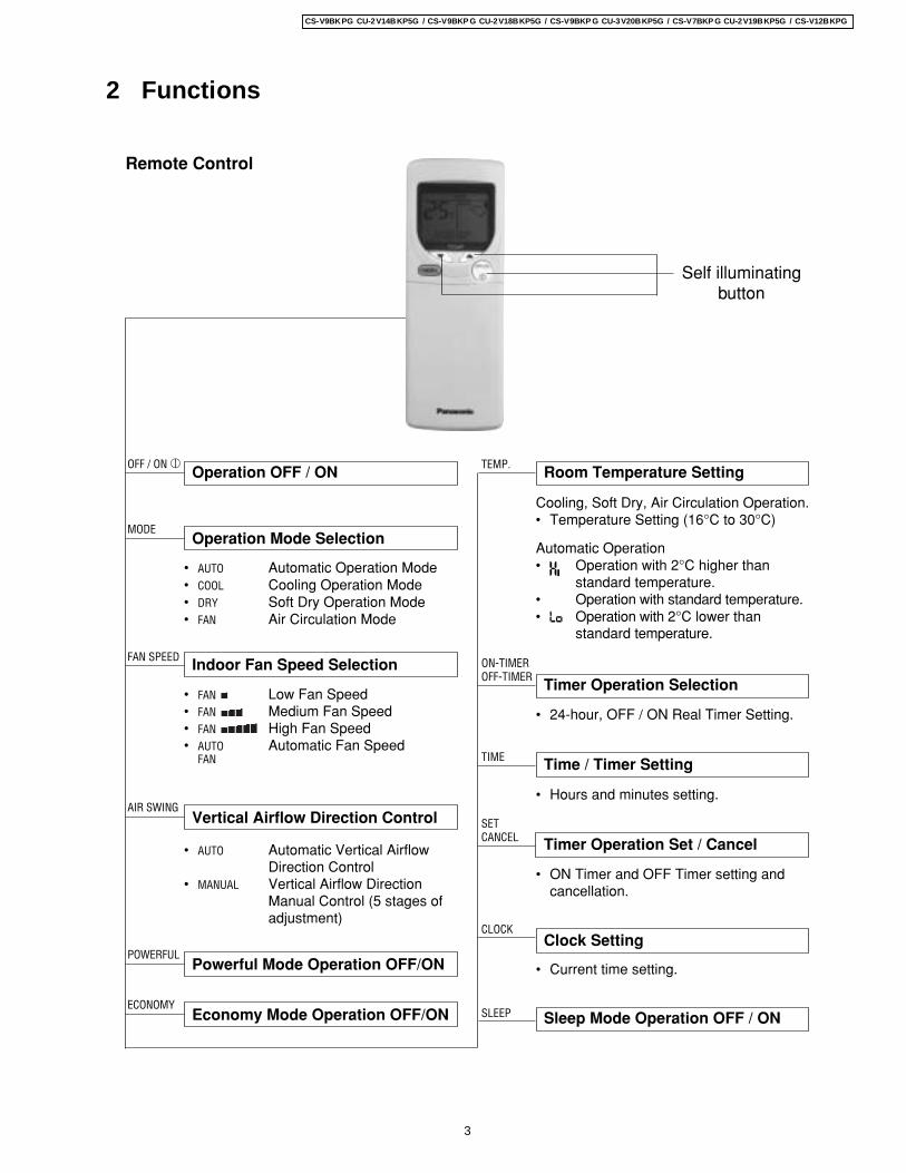
2 Functions
Remote Control
Operation OFF / ONOFF / ON I
Room Temperature SettingTEMP.
Operation Mode Selection
• AUTO Automatic Operation Mode• COOL Cooling Operation Mode• DRY Soft Dry Operation Mode• FAN Air Circulation Mode
MODE
TIME Time / Timer Setting
• Hours and minutes setting.
Clock Setting
• Current time setting.
Sleep Mode Operation OFF / ONSLEEP
Indoor Fan Speed SelectionFAN SPEED
• FAN Low Fan Speed• FAN Medium Fan Speed• FAN High Fan Speed• AUTO Automatic Fan Speed
FAN
• 24-hour, OFF / ON Real Timer Setting.
ON-TIMEROFF-TIMER
Timer Operation Selection
SETCANCEL Timer Operation Set / Cancel
• ON Timer and OFF Timer setting andcancellation.
CLOCK
AIR SWING
• AUTO Automatic Vertical AirflowDirection Control
• MANUAL Vertical Airflow DirectionManual Control (5 stages ofadjustment)
Powerful Mode Operation OFF/ONPOWERFUL
Economy Mode Operation OFF/ONECONOMY
Cooling, Soft Dry, Air Circulation Operation.• Temperature Setting (16°C to 30°C)
Automatic Operation• Operation with 2°C higher than
standard temperature.• Operation with standard temperature.• Operation with 2°C lower than
standard temperature.
Self illuminatingbutton
Vertical Airflow Direction Control
3
CS-V9BKPG CU-2V14BKP5G / CS-V9BKP G CU-2V18BKP5G / CS-V9BKP G CU-3V20BKP5G / CS-V7BKP G CU-2V19BKP5G / CS-V12BKPG
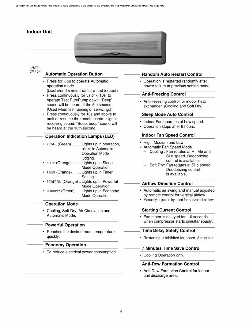
Indoor Unit
Random Auto Restart Control
• Operation is restarted randomly afterpower failure at previous setting mode.
Anti-Freezing Control
• Anti-Freezing control for indoor heatexchanger. (Cooling and Soft Dry)
Sleep Mode Auto Control
• Indoor Fan operates at Low speed.• Operation stops after 8 hours.
Indoor Fan Speed Control
• High, Medium and Low.• Automatic Fan Speed Mode
– Cooling : Fan rotates at Hi, Me andSLo speed. Deodorizingcontrol is available.
– Soft Dry: Fan rotates at SLo speed.Deodorizing controlis available.
• Automatic air swing and manual adjustedby remote control for vertical airflow.
• Manually adjusted by hand for horizontal airflow.
Airflow Direction Control
Automatic Operation Button
• Press for < 5s to operate Automaticoperation mode.(Used when the remote control cannot be used.)
• Press continuously for 5s or < 10s tooperate Test Run/Pump down. “Beep”sound will be heard at the 5th second.(Used when test running or servicing.)
• Press continuously for 10s and above toomit or resume the remote control signalreceiving sound. “Beep, beep” sound willbe heard at the 10th second.
AUTOOFF / ON
Operation Indication Lamps (LED)
• POWER (Green) ........ Lights up in operation,blinks in AutomaticOperation Modejudging.
• SLEEP (Orange) ........ Lights up in SleepMode Operation.
• TIMER (Orange) ....... Lights up in TimerSetting.
• POWERFUL (Orange) .. Lights up in PowerfulMode Operation.
• ECONOMY (Green) ..... Lights up in EconomyMode Operation.
Operation Mode
• Cooling, Soft Dry, Air Circulation andAutomatic Mode.
Powerful Operation
• Reaches the desired room temperaturequickly.
Time Delay Safety Control
• Restarting is inhibited for appro. 3 minutes.
Starting Current Control
Economy Operation
• To reduce electrical power consumption.7 Minutes Time Save Control
• Cooling Operation only.
Anti-Dew Formation Control
• Anti-Dew Formation Control for indoorunit discharge area.
• Fan motor is delayed for 1.6 secondswhen compressor starts simultaneously.
4
CS-V9BKPG CU-2V14BKP5G / CS-V9BKP G CU-2V18BKP5G / CS-V9BKP G CU-3V20BKP5G / CS-V7BKP G CU-2V19BKP5G / CS-V12BKPG
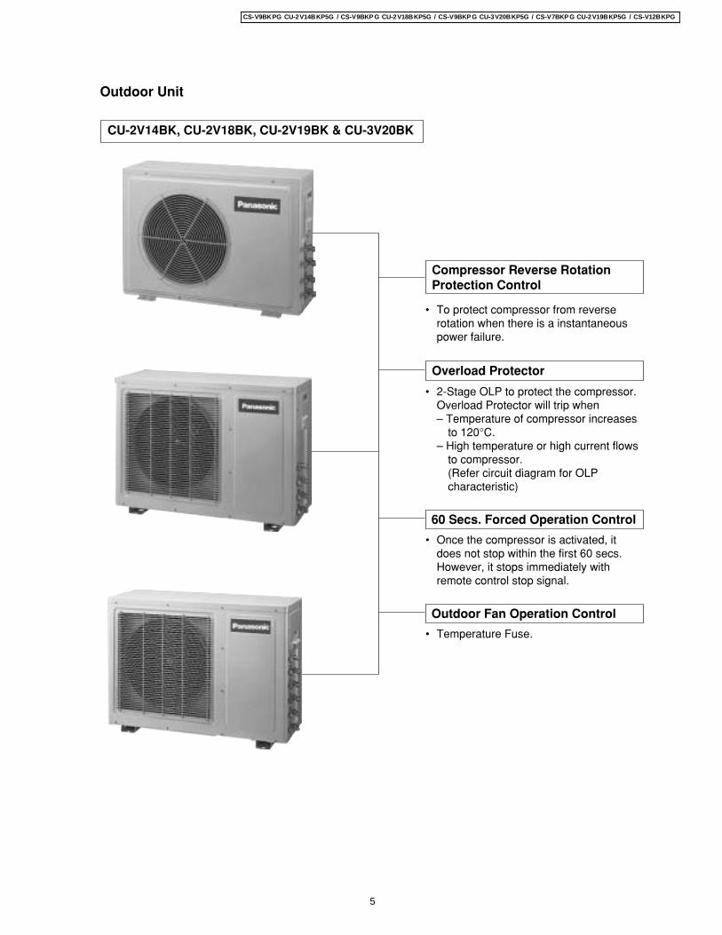
Outdoor Unit
• To protect compressor from reverserotation when there is a instantaneouspower failure.
60 Secs. Forced Operation Control
• Once the compressor is activated, itdoes not stop within the first 60 secs.However, it stops immediately withremote control stop signal.
Overload Protector
• 2-Stage OLP to protect the compressor.Overload Protector will trip when– Temperature of compressor increases
to 120°C.– High temperature or high current flows
to compressor.(Refer circuit diagram for OLPcharacteristic)
Compressor Reverse RotationProtection Control
Outdoor Fan Operation Control
• Temperature Fuse.
CU-2V14BK, CU-2V18BK, CU-2V19BK & CU-3V20BK
5
CS-V9BKPG CU-2V14BKP5G / CS-V9BKP G CU-2V18BKP5G / CS-V9BKP G CU-3V20BKP5G / CS-V7BKP G CU-2V19BKP5G / CS-V12BKPG
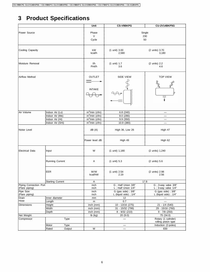
3 Product SpecificationsUnit CS-V9BKPG CU-2V14BKP5G
Power Source Phase SingleV 230
Cycle 50
Cooling Capacity kWkcal/h
(1 unit) 3.002,580
(2 units) 3.703,180
Moisture Removal l/hPint/h
(1 unit) 1.73.6
(2 units) 2.24.6
Airflow Method OUTLET
INTAKE
SIDE VIEW TOP VIEW
Air Volume Indoor Air (Lo) m3/min (cfm) 6.8 (240) —Indoor Air (Me) m3/min (cfm) 8.0 (280) —Indoor Air (Hi) m3/min (cfm) 9.9 (350) —Indoor Air (SHi) m3/min (cfm) 10.9 (380) —
Noise Level dB (A) High 36, Low 26 High 47
Power level dB High 49 High 62
Electrical Data Input W (1 unit) 1,180 (2 units) 1,240
Running Current A (1 unit) 5.3 (2 units) 5.6
EER W/Wkcal/hW
(1 unit) 2.542.19
(2 units) 2.982.56
Starting Current A 17.8Piping Connection Port(Flare piping)
inchinch
G ; Half Union 3/8”L ; Half Union 1/4”
G ; 3-way valve 3/8”L ; 3-way valve 1/4”
Pipe Size(Flare piping)
inchinch
G (gas side) ; 3/8”L (liquid side) ; 1/4”
G (gas side) ; 3/8”L (liquid side) ; 1/4”
DrainHose
Inner diameter mm 12 —Length m 0.7 —
Dimensions Height inch (mm) 10 - 13/16 (275) 21 - 1/4 (540)Width inch (mm) 31 - 15/32 (799) 29 - 15/16 (760)Depth inch (mm) 8 - 9/32 (210) 9 - 7/8 (250)
Net Weight lb (kg) 20 (9.0) 75 (34.0)Compressor Type — Rotary (1 cylinder)
rolling piston typeMotor Type — Induction (2-poles)Rated Output W — 830
6
CS-V9BKPG CU-2V14BKP5G / CS-V9BKP G CU-2V18BKP5G / CS-V9BKP G CU-3V20BKP5G / CS-V7BKP G CU-2V19BKP5G / CS-V12BKPG

Air Circulation Type Cross-flow Fan Propeller FanMaterial AS + Glass Fiber 20% AS + Glass Fiber 20%
Motor Type Induction (4-poles) Induction (6-poles)Input W 29.3 39.4Rated Output W 15 15
Fan Speed Low rpm 800 —Medium rpm 940 —High rpm 1,160 795SuperHigh rpm 1,250 —
Heat Exchanger Description Evaporator CondenserTube material Copper CopperFin material Aluminium AluminiumFin Type Slit Fin Louver FinRow / Stage (Plate fin configuration, forced draft)
2 × 15 1 × 20FPI 19 17Size (W × H × L) mm 610 × 315 × 25.4 687 × 508 × 22
Refrigerant Control Device — Capillary TubeRefrigeration Oil (c.c) — SUNISO 4GDID or ATMOS M60
(330)Refrigerant (R410A) g (oz) — 970 (34.2)Thermostat Electronic Control —Protection Device — Overload ProtectorCapillary Tube Length mm — 615
Flow Rate l/min — 14.4Inner Diameter mm — 1.6
Air Filter MaterialStyle
(c.c) P.P.Honeycomb
—
Capacity Control Capillary TubeCompressor Capacitor µF, VAC — 35 µF, 400 VACFan Motor Capacitor µF, VAC 1.5 µF, 400 VAC 1.0 µF, 430 VAC
• Specifications are subject to change without notice for further improvement .
7
CS-V9BKPG CU-2V14BKP5G / CS-V9BKP G CU-2V18BKP5G / CS-V9BKP G CU-3V20BKP5G / CS-V7BKP G CU-2V19BKP5G / CS-V12BKPG
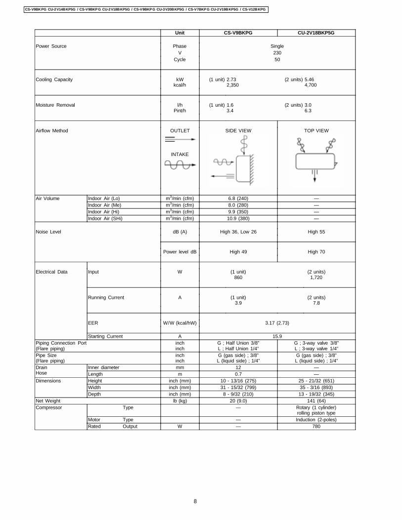
Unit CS-V9BKPG CU-2V18BKP5G
Power Source Phase SingleV 230
Cycle 50
Cooling Capacity kWkcal/h
(1 unit) 2.732,350
(2 units) 5.464,700
Moisture Removal l/hPint/h
(1 unit) 1.63.4
(2 units) 3.06.3
Airflow Method OUTLET
INTAKE
SIDE VIEW TOP VIEW
Air Volume Indoor Air (Lo) m3/min (cfm) 6.8 (240) —Indoor Air (Me) m3/min (cfm) 8.0 (280) —Indoor Air (Hi) m3/min (cfm) 9.9 (350) —Indoor Air (SHi) m3/min (cfm) 10.9 (380) —
Noise Level dB (A) High 36, Low 26 High 55
Power level dB High 49 High 70
Electrical Data Input W (1 unit)860
(2 units)1,720
Running Current A (1 unit)3.9
(2 units)7.8
EER W/W (kcal/hW) 3.17 (2.73)
Starting Current A 15.9Piping Connection Port(Flare piping)
inchinch
G ; Half Union 3/8”L ; Half Union 1/4”
G ; 3-way valve 3/8”L ; 3-way valve 1/4”
Pipe Size(Flare piping)
inchinch
G (gas side) ; 3/8”L (liquid side) ; 1/4”
G (gas side) ; 3/8”L (liquid side) ; 1/4”
DrainHose
Inner diameter mm 12 —Length m 0.7 —
Dimensions Height inch (mm) 10 - 13/16 (275) 25 - 21/32 (651)Width inch (mm) 31 - 15/32 (799) 35 - 3/16 (893)Depth inch (mm) 8 - 9/32 (210) 13 - 19/32 (345)
Net Weight lb (kg) 20 (9.0) 141 (64)Compressor Type — Rotary (1 cylinder)
rolling piston typeMotor Type — Induction (2-poles)Rated Output W — 780
8
CS-V9BKPG CU-2V14BKP5G / CS-V9BKP G CU-2V18BKP5G / CS-V9BKP G CU-3V20BKP5G / CS-V7BKP G CU-2V19BKP5G / CS-V12BKPG
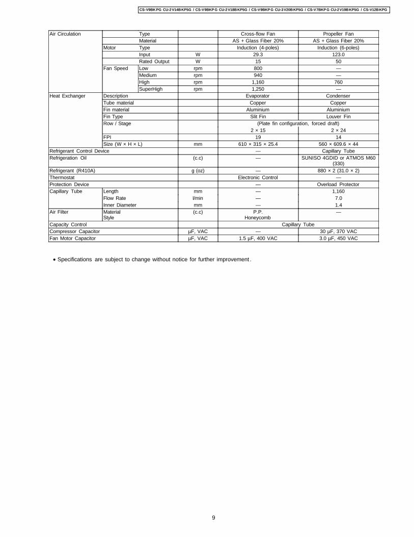
Air Circulation Type Cross-flow Fan Propeller FanMaterial AS + Glass Fiber 20% AS + Glass Fiber 20%
Motor Type Induction (4-poles) Induction (6-poles)Input W 29.3 123.0Rated Output W 15 50
Fan Speed Low rpm 800 —Medium rpm 940 —High rpm 1,160 760SuperHigh rpm 1,250 —
Heat Exchanger Description Evaporator CondenserTube material Copper CopperFin material Aluminium AluminiumFin Type Slit Fin Louver FinRow / Stage (Plate fin configuration, forced draft)
2 × 15 2 × 24FPI 19 14Size (W × H × L) mm 610 × 315 × 25.4 560 × 609.6 × 44
Refrigerant Control Device — Capillary TubeRefrigeration Oil (c.c) — SUNISO 4GDID or ATMOS M60
(330)Refrigerant (R410A) g (oz) — 880 × 2 (31.0 × 2)Thermostat Electronic Control —Protection Device — Overload ProtectorCapillary Tube Length mm — 1,160
Flow Rate l/min — 7.0Inner Diameter mm — 1.4
Air Filter MaterialStyle
(c.c) P.P.Honeycomb
—
Capacity Control Capillary TubeCompressor Capacitor µF, VAC — 30 µF, 370 VACFan Motor Capacitor µF, VAC 1.5 µF, 400 VAC 3.0 µF, 450 VAC
• Specifications are subject to change without notice for further improvement .
9
CS-V9BKPG CU-2V14BKP5G / CS-V9BKP G CU-2V18BKP5G / CS-V9BKP G CU-3V20BKP5G / CS-V7BKP G CU-2V19BKP5G / CS-V12BKPG
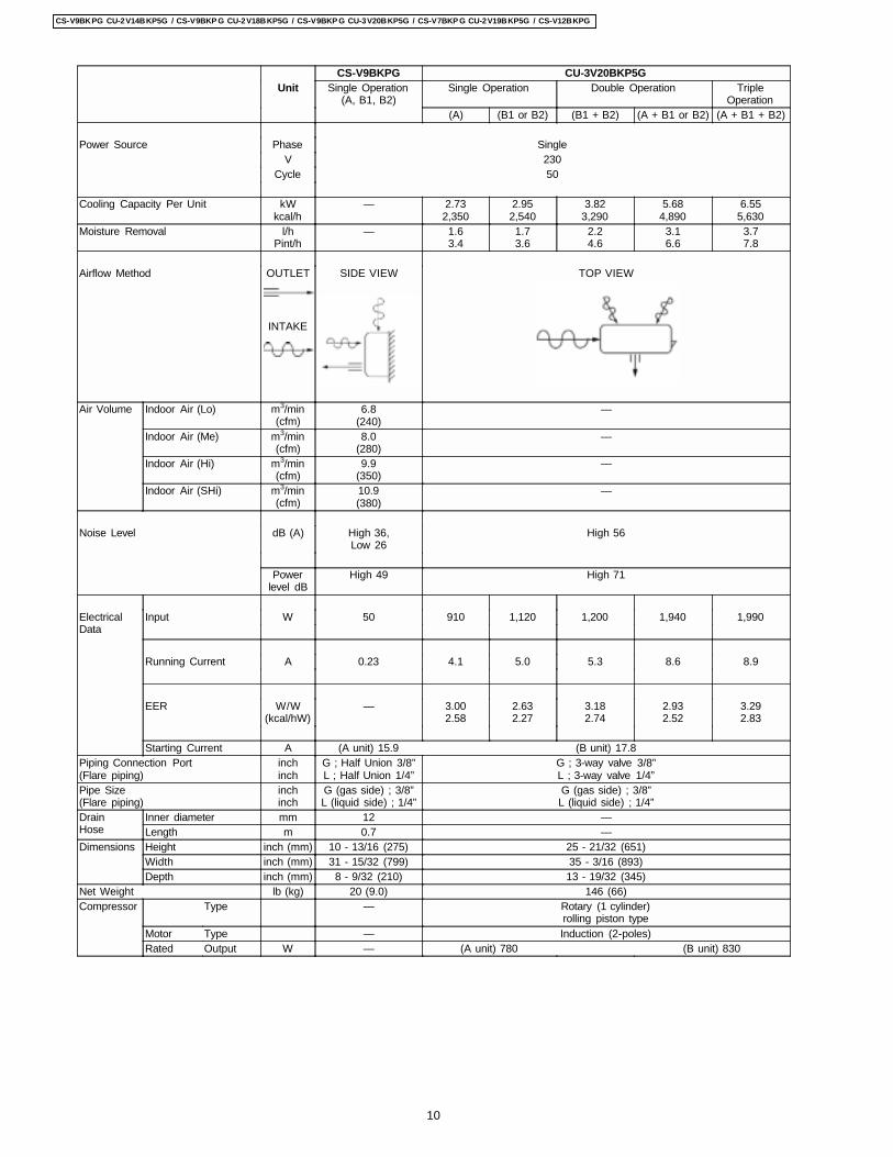
CS-V9BKPG CU-3V20BKP5GUnit Single Operation
(A, B1, B2)Single Operation Double Operation Triple
Operation(A) (B1 or B2) (B1 + B2) (A + B1 or B2) (A + B1 + B2)
Power Source Phase SingleV 230
Cycle 50
Cooling Capacity Per Unit kWkcal/h
— 2.732,350
2.952,540
3.823,290
5.684,890
6.555,630
Moisture Removal l/hPint/h
— 1.63.4
1.73.6
2.24.6
3.16.6
3.77.8
Airflow Method OUTLET
INTAKE
SIDE VIEW TOP VIEW
Air Volume Indoor Air (Lo) m3/min(cfm)
6.8(240)
—
Indoor Air (Me) m3/min(cfm)
8.0(280)
—
Indoor Air (Hi) m3/min(cfm)
9.9(350)
—
Indoor Air (SHi) m3/min(cfm)
10.9(380)
—
Noise Level dB (A) High 36,Low 26
High 56
Powerlevel dB
High 49 High 71
ElectricalData
Input W 50 910 1,120 1,200 1,940 1,990
Running Current A 0.23 4.1 5.0 5.3 8.6 8.9
EER W/W(kcal/hW)
— 3.002.58
2.632.27
3.182.74
2.932.52
3.292.83
Starting Current A (A unit) 15.9 (B unit) 17.8Piping Connection Port(Flare piping)
inchinch
G ; Half Union 3/8”L ; Half Union 1/4”
G ; 3-way valve 3/8”L ; 3-way valve 1/4”
Pipe Size(Flare piping)
inchinch
G (gas side) ; 3/8”L (liquid side) ; 1/4”
G (gas side) ; 3/8”L (liquid side) ; 1/4”
DrainHose
Inner diameter mm 12 —Length m 0.7 —
Dimensions Height inch (mm) 10 - 13/16 (275) 25 - 21/32 (651)Width inch (mm) 31 - 15/32 (799) 35 - 3/16 (893)Depth inch (mm) 8 - 9/32 (210) 13 - 19/32 (345)
Net Weight lb (kg) 20 (9.0) 146 (66)Compressor Type — Rotary (1 cylinder)
rolling piston typeMotor Type — Induction (2-poles)Rated Output W — (A unit) 780 (B unit) 830
10
CS-V9BKPG CU-2V14BKP5G / CS-V9BKP G CU-2V18BKP5G / CS-V9BKP G CU-3V20BKP5G / CS-V7BKP G CU-2V19BKP5G / CS-V12BKPG
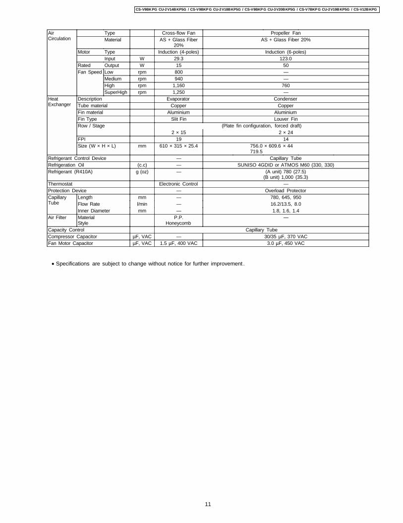
AirCirculation
Type Cross-flow Fan Propeller FanMaterial AS + Glass Fiber
20%AS + Glass Fiber 20%
Motor Type Induction (4-poles) Induction (6-poles)Input W 29.3 123.0
Rated Output W 15 50Fan Speed Low rpm 800 —
Medium rpm 940 —High rpm 1,160 760SuperHigh rpm 1,250 —
HeatExchanger
Description Evaporator CondenserTube material Copper CopperFin material Aluminium AluminiumFin Type Slit Fin Louver FinRow / Stage (Plate fin configuration, forced draft)
2 × 15 2 × 24FPI 19 14Size (W × H × L) mm 610 × 315 × 25.4 756.0
719.5× 609.6 × 44
Refrigerant Control Device — Capillary TubeRefrigeration Oil (c.c) — SUNISO 4GDID or ATMOS M60 (330, 330)Refrigerant (R410A) g (oz) — (A unit) 780 (27.5)
(B unit) 1,000 (35.3)Thermostat Electronic Control —Protection Device — Overload ProtectorCapillaryTube
Length mm — 780, 645, 950Flow Rate l/min — 16.2/13.5, 8.0Inner Diameter mm — 1.8, 1.6, 1.4
Air Filter MaterialStyle
P.P.Honeycomb
—
Capacity Control Capillary TubeCompressor Capacitor µF, VAC — 30/35 µF, 370 VACFan Motor Capacitor µF, VAC 1.5 µF, 400 VAC 3.0 µF, 450 VAC
• Specifications are subject to change without notice for further improvement .
11
CS-V9BKPG CU-2V14BKP5G / CS-V9BKP G CU-2V18BKP5G / CS-V9BKP G CU-3V20BKP5G / CS-V7BKP G CU-2V19BKP5G / CS-V12BKPG
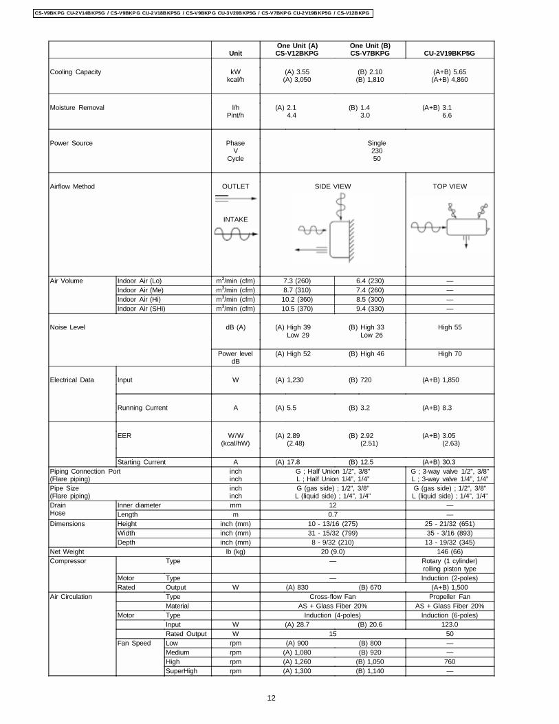
UnitOne Unit (A)CS-V12BKPG
One Unit (B)CS-V7BKPG CU-2V19BKP5G
Cooling Capacity kWkcal/h
(A) 3.55(A) 3,050
(B) 2.10(B) 1,810
(A+B) 5.65(A+B) 4,860
Moisture Removal l/hPint/h
(A) 2.14.4
(B) 1.43.0
(A+B) 3.16.6
Power Source PhaseV
Cycle
Single23050
Airflow Method OUTLET
INTAKE
SIDE VIEW TOP VIEW
Air Volume Indoor Air (Lo) m3/min (cfm) 7.3 (260) 6.4 (230) —Indoor Air (Me) m3/min (cfm) 8.7 (310) 7.4 (260) —Indoor Air (Hi) m3/min (cfm) 10.2 (360) 8.5 (300) —Indoor Air (SHi) m3/min (cfm) 10.5 (370) 9.4 (330) —
Noise Level dB (A) (A) High 39Low 29
(B) High 33Low 26
High 55
Power leveldB
(A) High 52 (B) High 46 High 70
Electrical Data Input W (A) 1,230 (B) 720 (A+B) 1,850
Running Current A (A) 5.5 (B) 3.2 (A+B) 8.3
EER W/W(kcal/hW)
(A) 2.89(2.48)
(B) 2.92(2.51)
(A+B) 3.05(2.63)
Starting Current A (A) 17.8 (B) 12.5 (A+B) 30.3Piping Connection Port(Flare piping)
inchinch
G ; Half Union 1/2”, 3/8”L ; Half Union 1/4”, 1/4”
G ; 3-way valve 1/2”, 3/8”L ; 3-way valve 1/4”, 1/4”
Pipe Size(Flare piping)
inchinch
G (gas side) ; 1/2”, 3/8”L (liquid side) ; 1/4”, 1/4”
G (gas side) ; 1/2”, 3/8”L (liquid side) ; 1/4”, 1/4”
DrainHose
Inner diameter mm 12 —Length m 0.7 —
Dimensions Height inch (mm) 10 - 13/16 (275) 25 - 21/32 (651)Width inch (mm) 31 - 15/32 (799) 35 - 3/16 (893)Depth inch (mm) 8 - 9/32 (210) 13 - 19/32 (345)
Net Weight lb (kg) 20 (9.0) 146 (66)Compressor Type — Rotary (1 cylinder)
rolling piston typeMotor Type — Induction (2-poles)Rated Output W (A) 830 (B) 670 (A+B) 1,500
Air Circulation Type Cross-flow Fan Propeller FanMaterial AS + Glass Fiber 20% AS + Glass Fiber 20%
Motor Type Induction (4-poles) Induction (6-poles)Input W (A) 28.7 (B) 20.6 123.0Rated Output W 15 50
Fan Speed Low rpm (A) 900 (B) 800 —Medium rpm (A) 1,080 (B) 920 —High rpm (A) 1,260 (B) 1,050 760SuperHigh rpm (A) 1,300 (B) 1,140 —
12
CS-V9BKPG CU-2V14BKP5G / CS-V9BKP G CU-2V18BKP5G / CS-V9BKP G CU-3V20BKP5G / CS-V7BKP G CU-2V19BKP5G / CS-V12BKPG
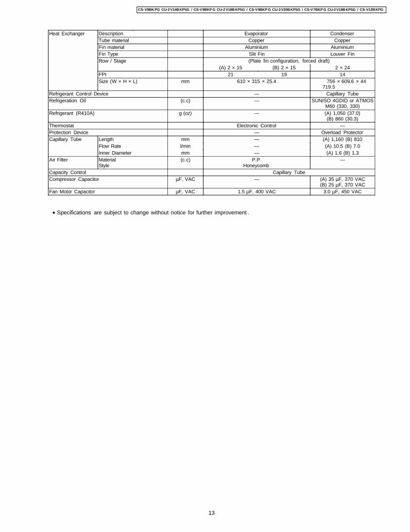
Heat Exchanger Description Evaporator CondenserTube material Copper CopperFin material Aluminium AluminiumFin Type Slit Fin Louver FinRow / Stage (Plate fin configuration, forced draft)
(A) 2 × 15 (B) 2 × 15 2 × 24FPI 21 19 14Size (W × H × L) mm 610 × 315 × 25.4 756
719.5× 609.6 × 44
Refrigerant Control Device — Capillary TubeRefrigeration Oil (c.c) — SUNISO 4GDID or ATMOS
M60 (330, 330)Refrigerant (R410A) g (oz) — (A) 1,050 (37.0)
(B) 860 (30.3)Thermostat Electronic Control —Protection Device — Overload ProtectorCapillary Tube Length mm — (A) 1,160 (B) 810
Flow Rate l/min — (A) 10.5 (B) 7.0Inner Diameter mm — (A) 1.6 (B) 1.3
Air Filter MaterialStyle
(c.c) P.P.Honeycomb
—
Capacity Control Capillary TubeCompressor Capacitor µF, VAC — (A) 35 µF, 370 VAC
(B) 25 µF, 370 VACFan Motor Capacitor µF, VAC 1.5 µF, 400 VAC 3.0 µF, 450 VAC
• Specifications are subject to change without notice for further improvement .
13
CS-V9BKPG CU-2V14BKP5G / CS-V9BKP G CU-2V18BKP5G / CS-V9BKP G CU-3V20BKP5G / CS-V7BKP G CU-2V19BKP5G / CS-V12BKPG
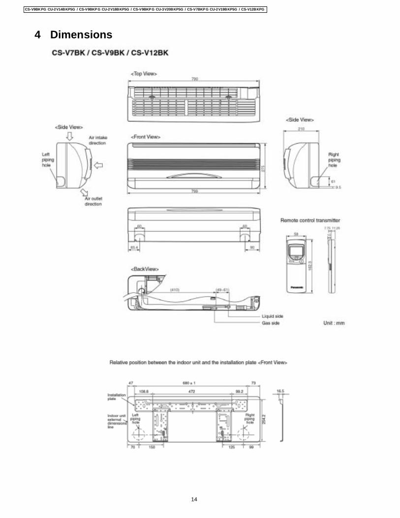
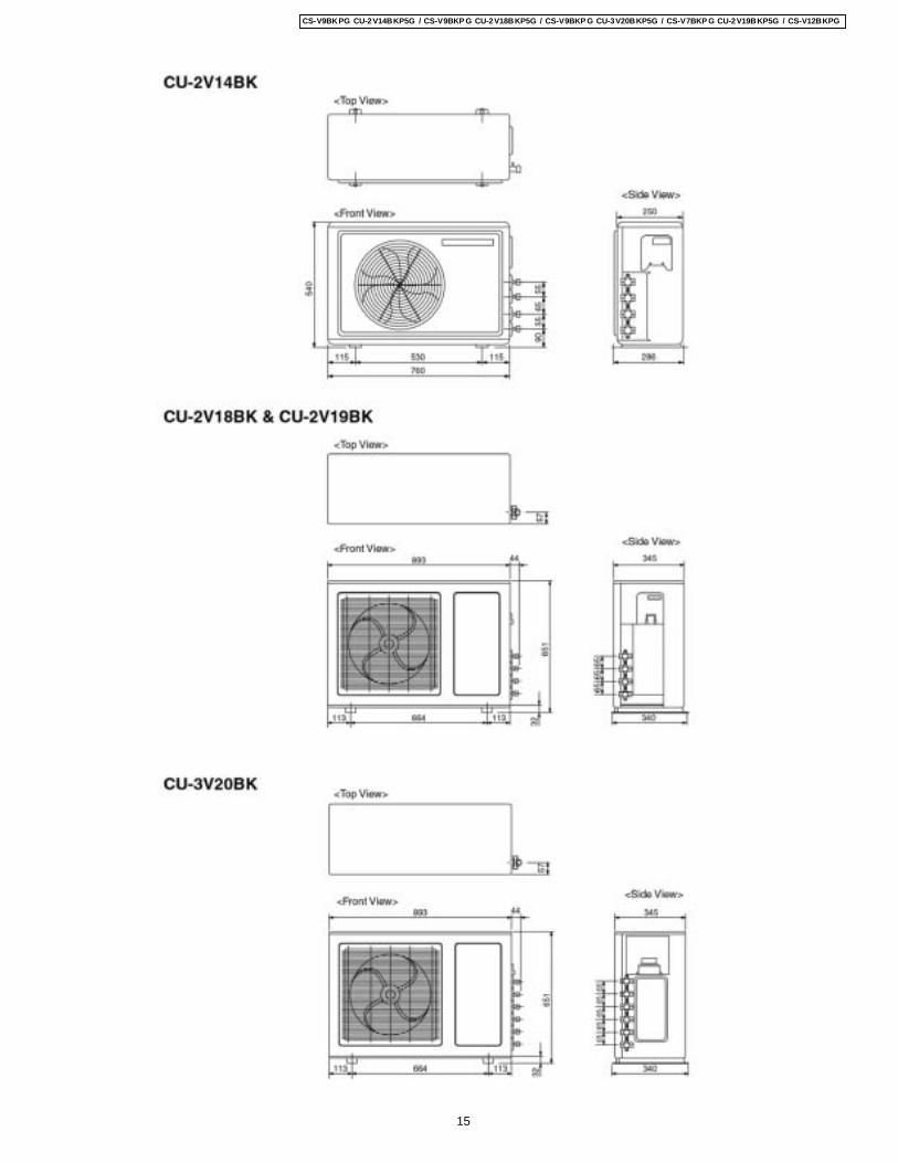
4 Dimensions
14
CS-V9BKPG CU-2V14BKP5G / CS-V9BKP G CU-2V18BKP5G / CS-V9BKP G CU-3V20BKP5G / CS-V7BKP G CU-2V19BKP5G / CS-V12BKPG
15
CS-V9BKPG CU-2V14BKP5G / CS-V9BKP G CU-2V18BKP5G / CS-V9BKP G CU-3V20BKP5G / CS-V7BKP G CU-2V19BKP5G / CS-V12BKPG
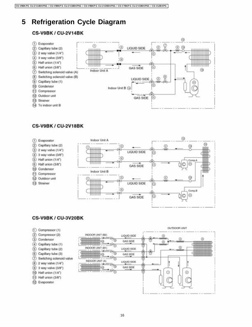
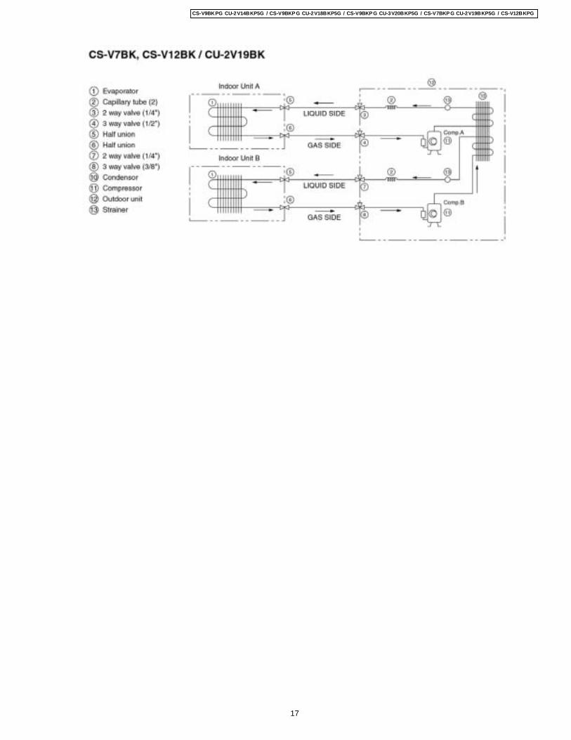
5 Refrigeration Cycle Diagram
16
CS-V9BKPG CU-2V14BKP5G / CS-V9BKP G CU-2V18BKP5G / CS-V9BKP G CU-3V20BKP5G / CS-V7BKP G CU-2V19BKP5G / CS-V12BKPG
17
CS-V9BKPG CU-2V14BKP5G / CS-V9BKP G CU-2V18BKP5G / CS-V9BKP G CU-3V20BKP5G / CS-V7BKP G CU-2V19BKP5G / CS-V12BKPG
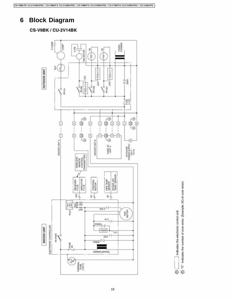
6 Block Diagram
18
CS-V9BKPG CU-2V14BKP5G / CS-V9BKP G CU-2V18BKP5G / CS-V9BKP G CU-3V20BKP5G / CS-V7BKP G CU-2V19BKP5G / CS-V12BKPG
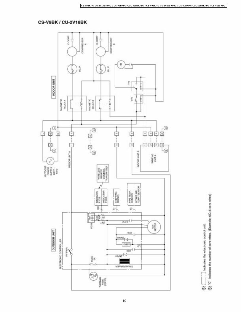
19
CS-V9BKPG CU-2V14BKP5G / CS-V9BKP G CU-2V18BKP5G / CS-V9BKP G CU-3V20BKP5G / CS-V7BKP G CU-2V19BKP5G / CS-V12BKPG
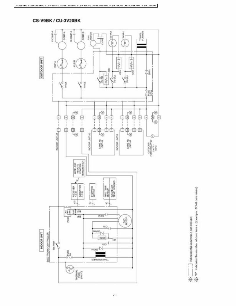
20
CS-V9BKPG CU-2V14BKP5G / CS-V9BKP G CU-2V18BKP5G / CS-V9BKP G CU-3V20BKP5G / CS-V7BKP G CU-2V19BKP5G / CS-V12BKPG
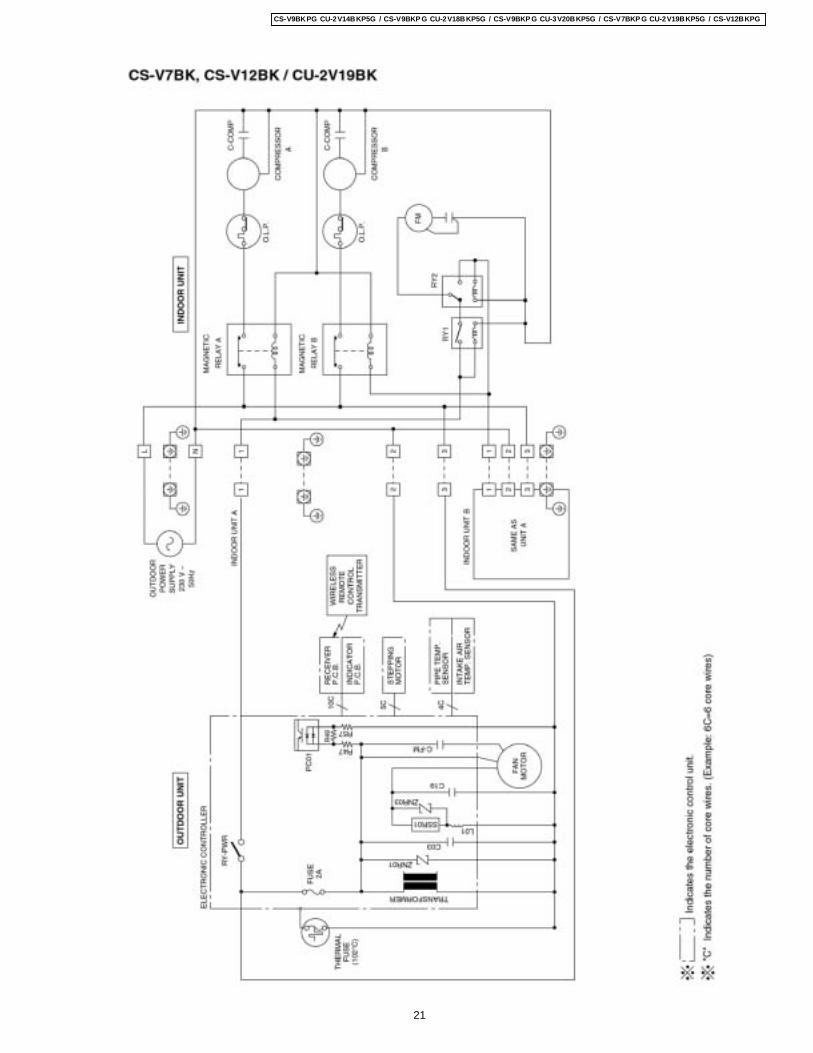
21
CS-V9BKPG CU-2V14BKP5G / CS-V9BKP G CU-2V18BKP5G / CS-V9BKP G CU-3V20BKP5G / CS-V7BKP G CU-2V19BKP5G / CS-V12BKPG
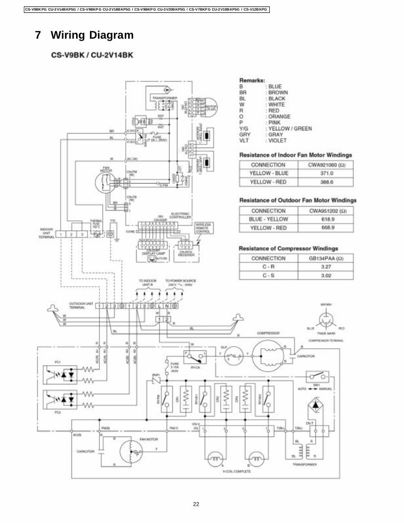
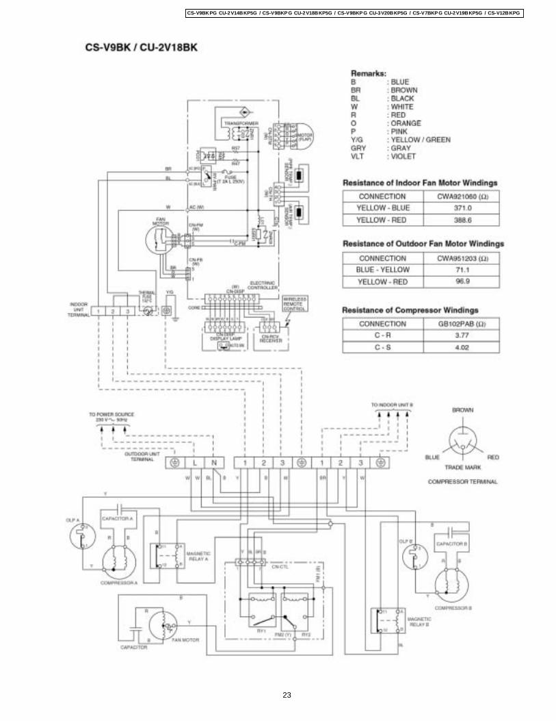
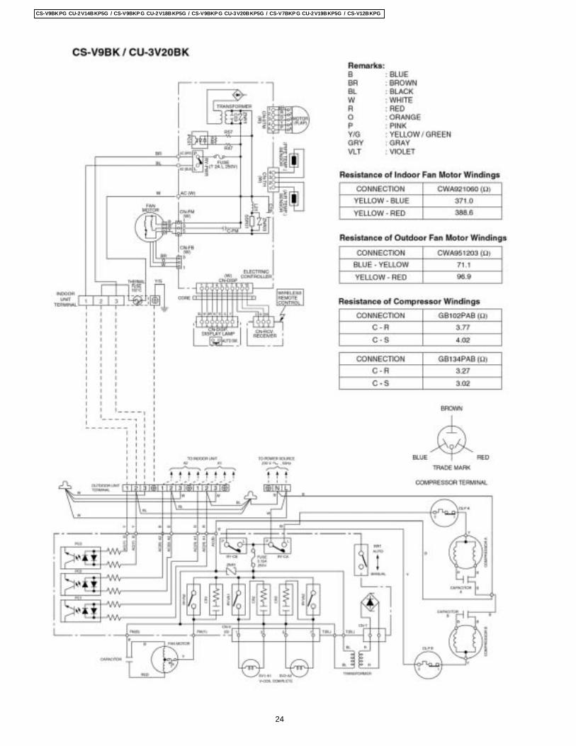
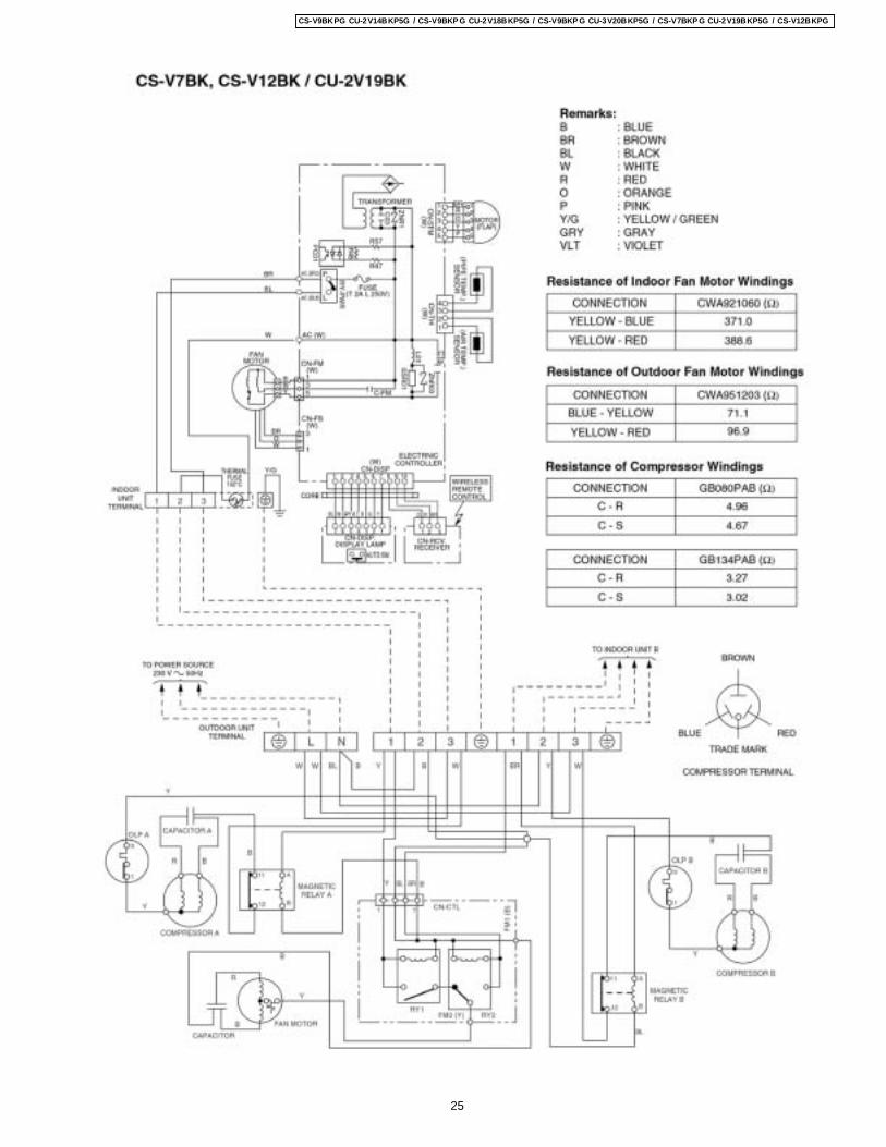
7 Wiring Diagram
22
CS-V9BKPG CU-2V14BKP5G / CS-V9BKP G CU-2V18BKP5G / CS-V9BKP G CU-3V20BKP5G / CS-V7BKP G CU-2V19BKP5G / CS-V12BKPG
23
CS-V9BKPG CU-2V14BKP5G / CS-V9BKP G CU-2V18BKP5G / CS-V9BKP G CU-3V20BKP5G / CS-V7BKP G CU-2V19BKP5G / CS-V12BKPG
24
CS-V9BKPG CU-2V14BKP5G / CS-V9BKP G CU-2V18BKP5G / CS-V9BKP G CU-3V20BKP5G / CS-V7BKP G CU-2V19BKP5G / CS-V12BKPG
25
CS-V9BKPG CU-2V14BKP5G / CS-V9BKP G CU-2V18BKP5G / CS-V9BKP G CU-3V20BKP5G / CS-V7BKP G CU-2V19BKP5G / CS-V12BKPG
Cooling in operation according to Remote Control setting.
Time Delay Safety Control (3 minutes)
7 minutes Time Save Control
Starting Current Control
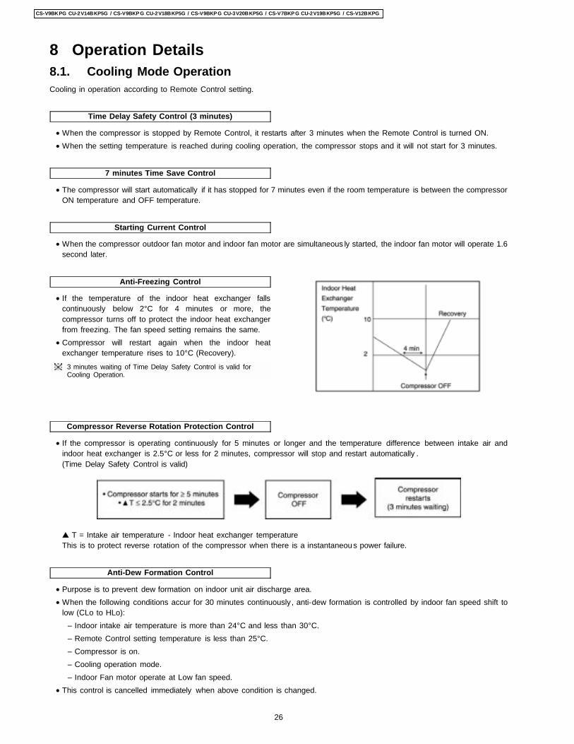
Anti-Freezing Control
• If the temperature of the indoor heat exchanger fallscontinuously below 2°C for 4 minutes or more, thecompressor turns off to protect the indoor heat exchangerfrom freezing. The fan speed setting remains the same.
• Compressor will restart again when the indoor heatexchanger temperature rises to 10°C (Recovery).
3 minutes waiting of Time Delay Safety Control is valid forCooling Operation.
Compressor Reverse Rotation Protection Control
Anti-Dew Formation Control
8 Operation Details8.1. Cooling Mode Operation
• When the compressor is stopped by Remote Control, it restarts after 3 minutes when the Remote Control is turned ON. • When the setting temperature is reached during cooling operation, the compressor stops and it will not start for 3 minutes.
• The compressor will start automatically if it has stopped for 7 minutes even if the room temperature is between the compressorON temperature and OFF temperature.
• When the compressor outdoor fan motor and indoor fan motor are simultaneous ly started, the indoor fan motor will operate 1.6second later.
• If the compressor is operating continuously for 5 minutes or longer and the temperature difference between intake air andindoor heat exchanger is 2.5°C or less for 2 minutes, compressor will stop and restart automatically .(Time Delay Safety Control is valid)
T = Intake air temperature - Indoor heat exchanger temperatureThis is to protect reverse rotation of the compressor when there is a instantaneous power failure.
• Purpose is to prevent dew formation on indoor unit air discharge area. • When the following conditions accur for 30 minutes continuously, anti-dew formation is controlled by indoor fan speed shift to
low (CLo to HLo): − Indoor intake air temperature is more than 24°C and less than 30°C. − Remote Control setting temperature is less than 25°C. − Compressor is on. − Cooling operation mode. − Indoor Fan motor operate at Low fan speed.
• This control is cancelled immediately when above condition is changed.
26
CS-V9BKPG CU-2V14BKP5G / CS-V9BKP G CU-2V18BKP5G / CS-V9BKP G CU-3V20BKP5G / CS-V7BKP G CU-2V19BKP5G / CS-V12BKPG

Automatic Fan Speed Mode
Cooling Operation Time Diagram
When Automatic Fan Speed is selected at Remote Control during cooling operation. • Fan speed rotates in the range of Hi to Me. • Deodorizing Control.
27
CS-V9BKPG CU-2V14BKP5G / CS-V9BKP G CU-2V18BKP5G / CS-V9BKP G CU-3V20BKP5G / CS-V7BKP G CU-2V19BKP5G / CS-V12BKPG
Time Delay Safety Control
Starting Current Control
Anti-Freezing Control
Compressor Reverse Rotation Protection Control
Anti-Dew Formation Control
Automatic Fan Speed Mode
8.2. Soft Dry Mode Operation
• The unit starts cooling operation until the room temperature reaches the setting temperature set on the Remote Control, andthen Soft Dry operation will start.
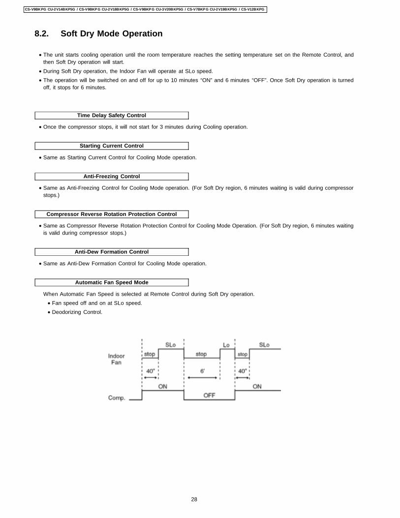
• During Soft Dry operation, the Indoor Fan will operate at SLo speed. • The operation will be switched on and off for up to 10 minutes “ON” and 6 minutes “OFF”. Once Soft Dry operation is turned
off, it stops for 6 minutes.
• Once the compressor stops, it will not start for 3 minutes during Cooling operation.
• Same as Starting Current Control for Cooling Mode operation.
• Same as Anti-Freezing Control for Cooling Mode operation. (For Soft Dry region, 6 minutes waiting is valid during compressorstops.)
• Same as Compressor Reverse Rotation Protection Control for Cooling Mode Operation. (For Soft Dry region, 6 minutes waitingis valid during compressor stops.)
• Same as Anti-Dew Formation Control for Cooling Mode operation.
When Automatic Fan Speed is selected at Remote Control during Soft Dry operation. • Fan speed off and on at SLo speed. • Deodorizing Control.
28
CS-V9BKPG CU-2V14BKP5G / CS-V9BKP G CU-2V18BKP5G / CS-V9BKP G CU-3V20BKP5G / CS-V7BKP G CU-2V19BKP5G / CS-V12BKPG
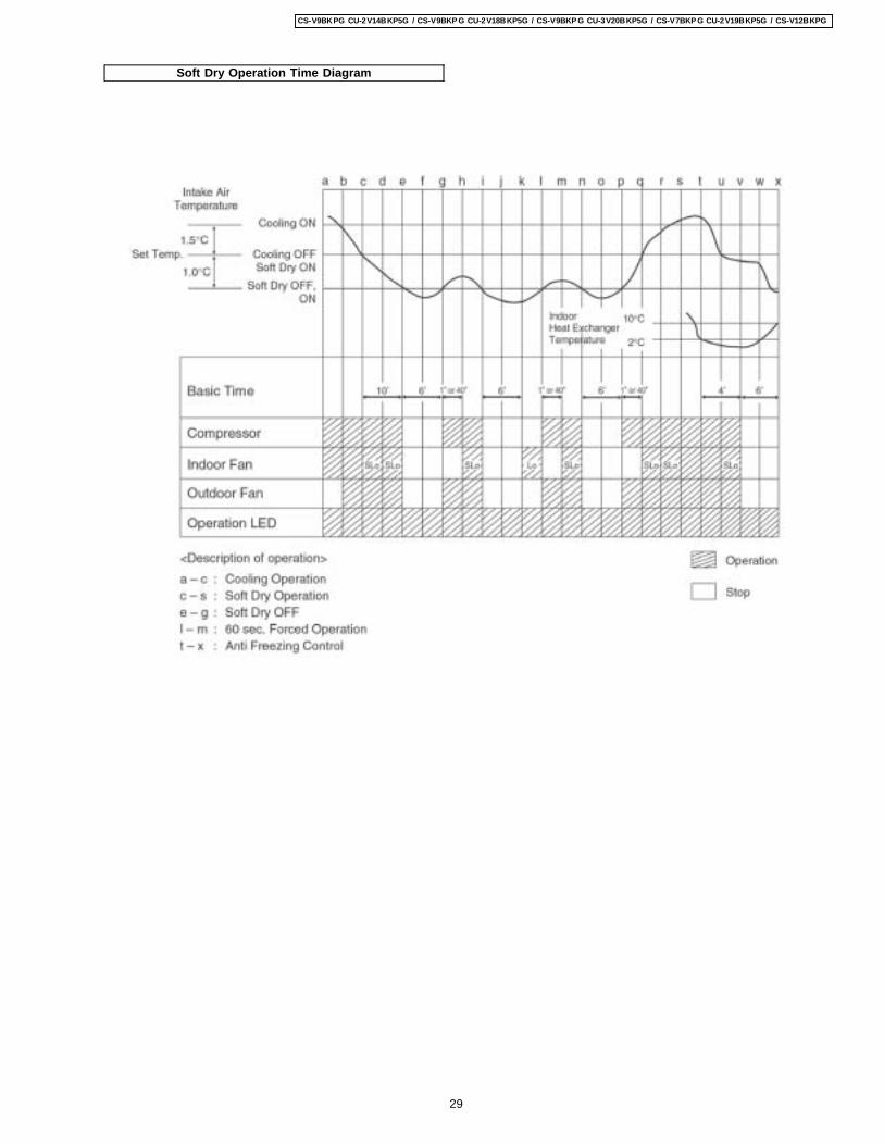
Soft Dry Operation Time Diagram
29
CS-V9BKPG CU-2V14BKP5G / CS-V9BKP G CU-2V18BKP5G / CS-V9BKP G CU-3V20BKP5G / CS-V7BKP G CU-2V19BKP5G / CS-V12BKPG
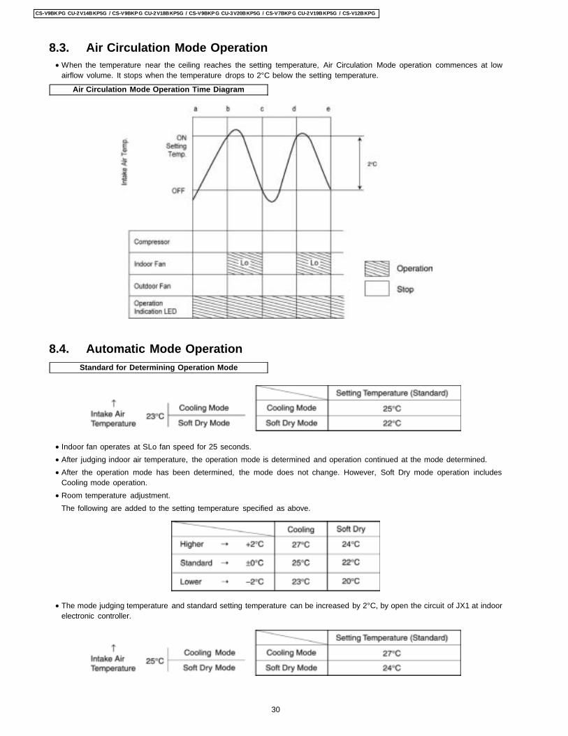
Air Circulation Mode Operation Time Diagram
Standard for Determining Operation Mode
8.3. Air Circulation Mode Operation • When the temperature near the ceiling reaches the setting temperature, Air Circulation Mode operation commences at low
airflow volume. It stops when the temperature drops to 2°C below the setting temperature.
8.4. Automatic Mode Operation
• Indoor fan operates at SLo fan speed for 25 seconds. • After judging indoor air temperature, the operation mode is determined and operation continued at the mode determined. • After the operation mode has been determined, the mode does not change. However, Soft Dry mode operation includes
Cooling mode operation. • Room temperature adjustment.
The following are added to the setting temperature specified as above.
• The mode judging temperature and standard setting temperature can be increased by 2°C, by open the circuit of JX1 at indoorelectronic controller.
30
CS-V9BKPG CU-2V14BKP5G / CS-V9BKP G CU-2V18BKP5G / CS-V9BKP G CU-3V20BKP5G / CS-V7BKP G CU-2V19BKP5G / CS-V12BKPG
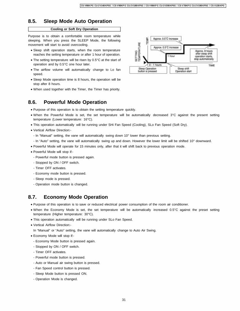
Cooling or Soft Dry Operation
Purpose is to obtain a comfortable room temperature whilesleeping. When you press the SLEEP Mode, the followingmovement will start to avoid overcooling. • Sleep shift operation starts, when the room temperature
reaches the setting temperature or after 1 hour of operation. • The setting temperature will be risen by 0.5°C at the start of
operation and by 0.5°C one hour later. • The airflow volume will automatically change to Lo fan
speed. • Sleep Mode operation time is 8 hours, the operation will be
stop after 8 hours. • When used together with the Timer, the Timer has priority.
8.5. Sleep Mode Auto Operation
8.6. Powerful Mode Operation • Purpose of this operation is to obtain the setting temperature quickly. • When the Powerful Mode is set, the set temperature will be automatically decreased 3°C against the present setting
temperature (Lower temperature: 16°C). • This operation automatically will be running under SHi Fan Speed (Cooling), SLo Fan Speed (Soft Dry). • Vertical Airflow Direction:-
- In “Manual” setting, the vane will automatically swing down 10° lower than previous setting.- In “Auto” setting, the vane will automatically swing up and down. However the lower limit will be shifted 10° downward.
• Powerful Mode will operate for 15 minutes only, after that it will shift back to previous operation mode. • Powerful Mode will stop if:-
- Powerful mode button is pressed again.- Stopped by ON / OFF switch.- Timer OFF activates.- Economy mode button is pressed.- Sleep mode is pressed.- Operation mode button is changed.
8.7. Economy Mode Operation • Purpose of this operation is to save or reduced electrical power consumption of the room air conditioner. • When the Economy Mode is set, the set temperature will be automatically increased 0.5°C against the preset setting
temperature (Higher temperature: 30°C). • This operation automatically will be running under SLo Fan Speed. • Vertical Airflow Direction:-
In “Manual” or “Auto” setting, the vane will automatically change to Auto Air Swing. • Economy Mode will stop if:-
- Economy Mode button is pressed again.- Stopped by ON / OFF switch.- Timer OFF activates.- Powerful mode button is pressed.- Auto or Manual air swing button is pressed.- Fan Speed control button is pressed.- Sleep Mode button is pressed ON.- Operation Mode is changed.
31
CS-V9BKPG CU-2V14BKP5G / CS-V9BKP G CU-2V18BKP5G / CS-V9BKP G CU-3V20BKP5G / CS-V7BKP G CU-2V19BKP5G / CS-V12BKPG
8.8. Random Auto Restart Control
• If there is a power failure, operation will be automatically restarted after 3 to 4 minutes when the power is resumed.It will start with previous operation mode and airflow direction.
• Restart time is decided randomly using 4 parameter:-Intake air temperature, setting temperature, fan speed and Air Swing Blade position.
• Auto Restart Control is not available when Timer or Sleep Mode is set. • This control can be omitted by open the circuit of JX2. (Refer Circuit Diagram)
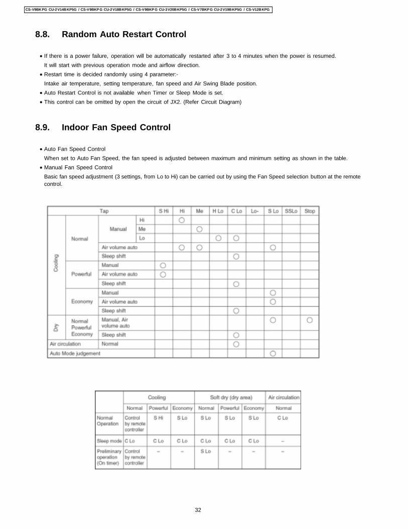
8.9. Indoor Fan Speed Control
• Auto Fan Speed ControlWhen set to Auto Fan Speed, the fan speed is adjusted between maximum and minimum setting as shown in the table.
• Manual Fan Speed ControlBasic fan speed adjustment (3 settings, from Lo to Hi) can be carried out by using the Fan Speed selection button at the remotecontrol.
32
CS-V9BKPG CU-2V14BKP5G / CS-V9BKP G CU-2V18BKP5G / CS-V9BKP G CU-3V20BKP5G / CS-V7BKP G CU-2V19BKP5G / CS-V12BKPG
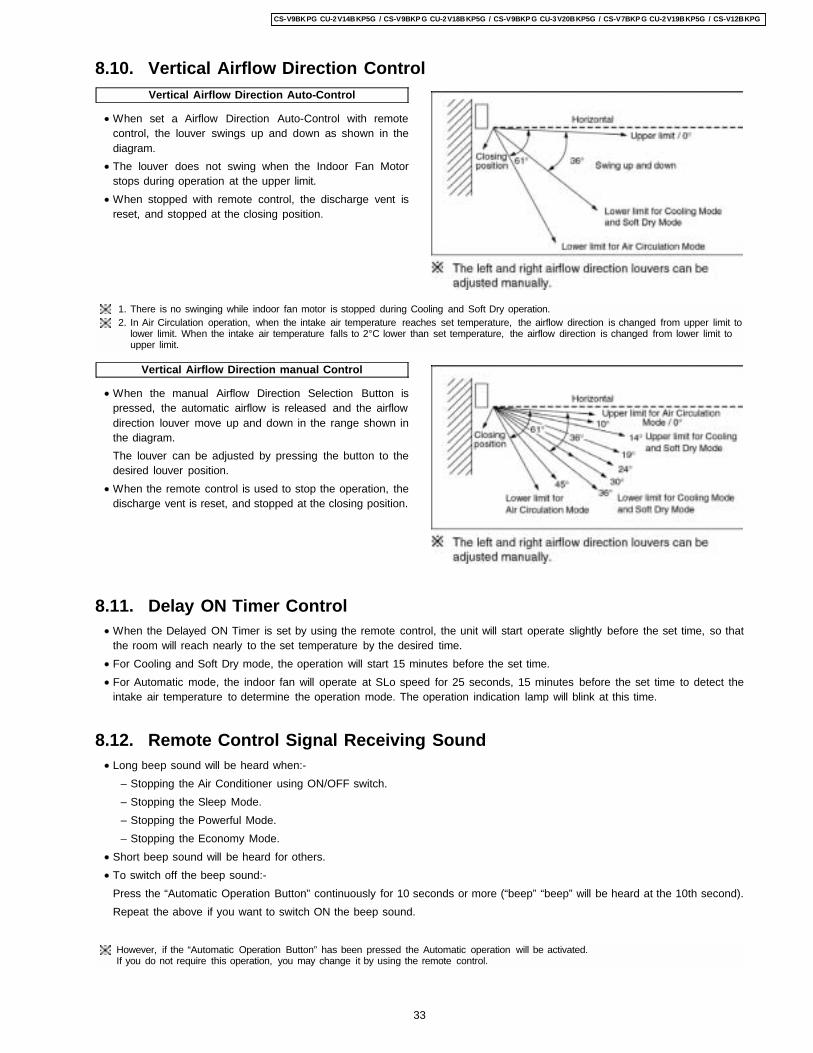
Vertical Airflow Direction Auto-Control
• When set a Airflow Direction Auto-Control with remotecontrol, the louver swings up and down as shown in thediagram.
• The louver does not swing when the Indoor Fan Motorstops during operation at the upper limit.
• When stopped with remote control, the discharge vent isreset, and stopped at the closing position.
Vertical Airflow Direction manual Control
• When the manual Airflow Direction Selection Button ispressed, the automatic airflow is released and the airflowdirection louver move up and down in the range shown inthe diagram.The louver can be adjusted by pressing the button to thedesired louver position.
• When the remote control is used to stop the operation, thedischarge vent is reset, and stopped at the closing position.
8.10. Vertical Airflow Direction Control
1. There is no swinging while indoor fan motor is stopped during Cooling and Soft Dry operation.2. In Air Circulation operation, when the intake air temperature reaches set temperature, the airflow direction is changed from upper limit to
lower limit. When the intake air temperature falls to 2°C lower than set temperature, the airflow direction is changed from lower limit toupper limit.
8.11. Delay ON Timer Control • When the Delayed ON Timer is set by using the remote control, the unit will start operate slightly before the set time, so that
the room will reach nearly to the set temperature by the desired time. • For Cooling and Soft Dry mode, the operation will start 15 minutes before the set time. • For Automatic mode, the indoor fan will operate at SLo speed for 25 seconds, 15 minutes before the set time to detect the
intake air temperature to determine the operation mode. The operation indication lamp will blink at this time.
8.12. Remote Control Signal Receiving Sound • Long beep sound will be heard when:-
− Stopping the Air Conditioner using ON/OFF switch. − Stopping the Sleep Mode. − Stopping the Powerful Mode. − Stopping the Economy Mode.
• Short beep sound will be heard for others. • To switch off the beep sound:-
Press the “Automatic Operation Button” continuously for 10 seconds or more (“beep” “beep” will be heard at the 10th second).Repeat the above if you want to switch ON the beep sound.
However, if the “Automatic Operation Button” has been pressed the Automatic operation will be activated.If you do not require this operation, you may change it by using the remote control.
33
CS-V9BKPG CU-2V14BKP5G / CS-V9BKP G CU-2V18BKP5G / CS-V9BKP G CU-3V20BKP5G / CS-V7BKP G CU-2V19BKP5G / CS-V12BKPG
9 Operating Instructions
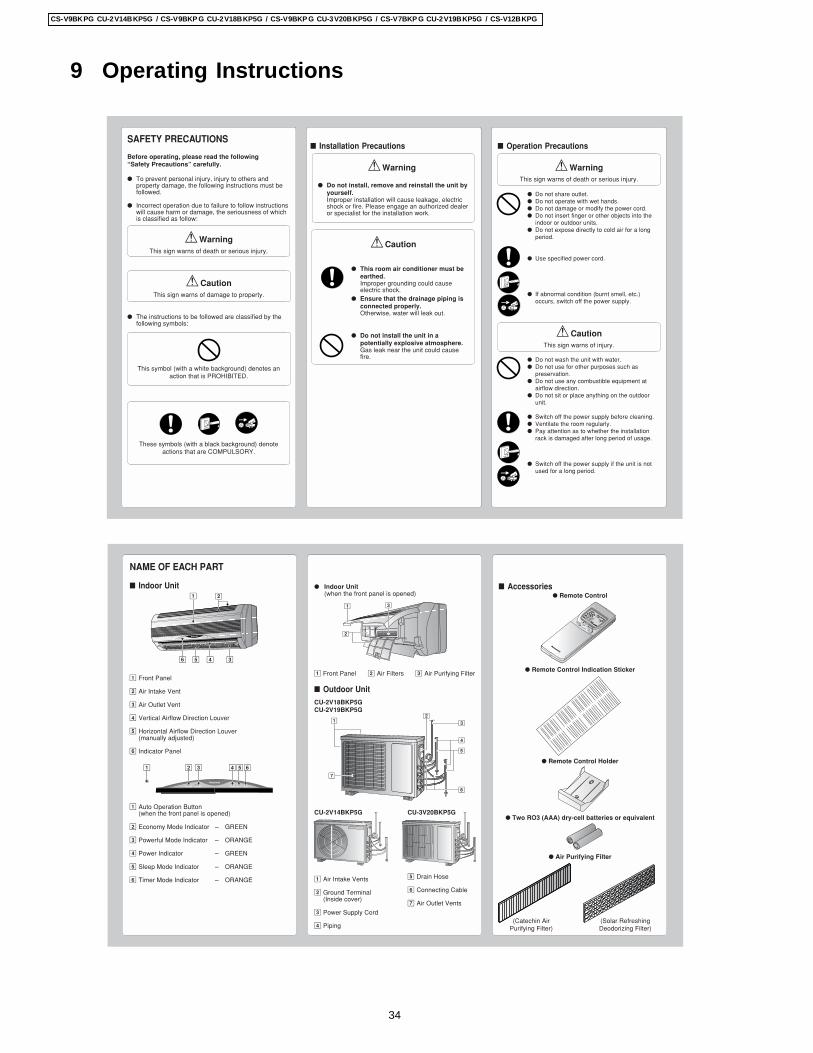
SAFETY PRECAUTIONS
Before operating, please read the following“Safety Precautions” carefully.
To prevent personal injury, injury to others andproperty damage, the following instructions must befollowed.
Incorrect operation due to failure to follow instructionswill cause harm or damage, the seriousness of whichis classified as follow:
! WarningThis sign warns of death or serious injury.
! CautionThis sign warns of damage to property.
The instructions to be followed are classified by thefollowing symbols:
This symbol (with a white background) denotes anaction that is PROHIBITED.
These symbols (with a black background) denoteactions that are COMPULSORY.
Installation Precautions
! Warning
This room air conditioner must beearthed.Improper grounding could causeelectric shock.
Ensure that the drainage piping isconnected properly.Otherwise, water will leak out.
Do not install the unit in apotentially explosive atmosphere.Gas leak near the unit could causefire.
Do not install, remove and reinstall the unit byyourself.Improper installation will cause leakage, electricshock or fire. Please engage an authorized dealeror specialist for the installation work.
! Caution
Operation Precautions
! WarningThis sign warns of death or serious injury.
Do not share outlet. Do not operate with wet hands. Do not damage or modify the power cord. Do not insert finger or other objects into the
indoor or outdoor units. Do not expose directly to cold air for a long
period.
Use specified power cord.
If abnormal condition (burnt smell, etc.)occurs, switch off the power supply.
! CautionThis sign warns of injury.
Do not wash the unit with water. Do not use for other purposes such as
preservation. Do not use any combustible equipment at
airflow direction. Do not sit or place anything on the outdoor
unit.
Switch off the power supply before cleaning. Ventilate the room regularly. Pay attention as to whether the installation
rack is damaged after long period of usage.
Switch off the power supply if the unit is notused for a long period.
OFF
OFF
OFF
NAME OF EACH PART
Indoor Unit
1 Front Panel
2 Air Intake Vent
3 Air Outlet Vent
4 Vertical Airflow Direction Louver
5 Horizontal Airflow Direction Louver(manually adjusted)
6 Indicator Panel
1 Auto Operation Button(when the front panel is opened)
2 Economy Mode Indicator – GREEN
3 Powerful Mode Indicator – ORANGE
4 Power Indicator – GREEN
5 Sleep Mode Indicator – ORANGE
6 Timer Mode Indicator – ORANGE
Indoor Unit(when the front panel is opened)
1 Front Panel 2 Air Filters 3 Air Purifying Filter
Outdoor UnitCU-2V18BKP5GCU-2V19BKP5G
CU-2V14BKP5G CU-3V20BKP5G
1 Air Intake Vents
2 Ground Terminal(Inside cover)
3 Power Supply Cord
4 Piping
Accessories Remote Control
Remote Control Indication Sticker
Remote Control Holder
Two RO3 (AAA) dry-cell batteries or equivalent
Air Purifying Filter
CHECK
TEMP
AUTUTO
ONOFF
FANAN
AUTUTO
RESET
BATTERY
CLOCK
MODE
SLEEP
ECONOMY
FAN SPEED
AIR SWING
OFF
CANCEL
ON
SET
Step 1
2
3TIMER
+
POWERFUL
OFF/ON
AUTUTO
DRDRYFANAN
COOLCOOL
1 2
346 5
2
1 3
12
7
3
4
5
6POWERFULPOWERFULECONOMYECONOMY POWERPOWER TIMERTIMERSLEEPSLEEPPOWERFULPOWERFULECONOMYECONOMY POWERPOWER TIMERTIMERSLEEPSLEEP
1 2 3 654
(Catechin AirPurifying Filter)
(Solar RefreshingDeodorizing Filter)
5 Drain Hose
6 Connecting Cable
7 Air Outlet Vents
34
CS-V9BKPG CU-2V14BKP5G / CS-V9BKP G CU-2V18BKP5G / CS-V9BKP G CU-3V20BKP5G / CS-V7BKP G CU-2V19BKP5G / CS-V12BKPG
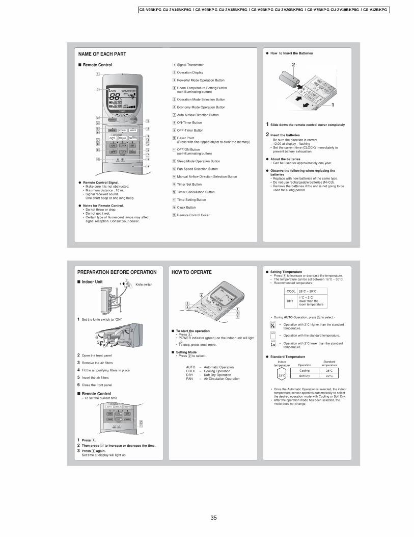
NAME OF EACH PART
Remote Control
Remote Control Signal.• Make sure it is not obstructed.• Maximum distance : 10 m.• Signal received sound.
One short beep or one long beep.
Notes for Remote Control.• Do not throw or drop.• Do not get it wet.• Certain type of fluorescent lamps may affect
signal reception. Consult your dealer.
CHECK
TEMP
AUTUTO
ON
OFF FANAN
AUTUTO
RESET CLOCK
MODE SLEEPECONOMY
FAN SPEED
AIR SWING
OFF CANCEL
ON SET1 2 3
TIMER
OFF/ONPOWERFUL
AUTO MANUAL
#
!
$
%
^
$
*
&
3
5
8
7
9
0
6
4
(
2
1
AUTUTO DRDRY FANANCOOLCOOL
How to Insert the Batteries
1 Slide down the remote control cover completely
2 Insert the batteries– Be sure the direction is correct– 12.00 at display - flashing• Set the current time (CLOCK) immediately to
prevent battery exhaustion.
About the batteries• Can be used for approximately one year.
Observe the following when replacing thebatteries• Replace with new batteries of the same type.• Do not use rechargeable batteries (Ni-Cd).• Remove the batteries if the unit is not going to be
used for a long period.
1 Signal Transmitter
2 Operation Display
3 Powerful Mode Operation Button
4 Room Temperature Setting Button(self-illuminating button)
5 Operation Mode Selection Button
6 Economy Mode Operation Button
7 Auto Airflow Direction Button
8 ON-Timer Button
9 OFF-Timer Button
0 Reset Point(Press with fine-tipped object to clear the memory)
! OFF/ON Button(self-illuminating button)
@ Sleep Mode Operation Button
# Fan Speed Selection Button
$ Manual Airflow Direction Selection Button
% Timer Set Button
^ Timer Cancellation Button
& Time-Setting Button
* Clock Button
( Remote Control Cover
CHECK
OF
RESETCLOCK
AIR SWING
OFF
CANCEL
1
2
3TIMER
POWERFUL
AUTOMANUAL
ECONOMYSLE
ON
SET
FAN SPEED
MODE
2
1
1.5V1.5V
PREPARATION BEFORE OPERATION
Indoor Unit
1 Set the knife switch to “ON”
2 Open the front panel
3 Remove the air filters
4 Fit the air purifying filters in place
5 Insert the air filters
6 Close the front panel
Remote Control– To set the current time
1 Press 1.
2 Then press 2 to increase or decrease the time.
3 Press 1 again.Set time at display will light up.
CHECK RESET CLOCK
FAN SPEED
AIR SWING
OFF CANCEL
ON SET1 2 3
TIMER
AUTO MANUAL
1
2
6
2
453
Setting Temperature• Press 3 to increase or decrease the temperature.• The temperature can be set between 16°C ~ 30°C.• Recommended temperature:
• During AUTO Operation, press 3 to select:-
• Operation with 2°C higher than the standardtemperature.
• Operation with the standard temperature.
• Operation with 2°C lower than the standardtemperature.
Standard Temperature
• Once the Automatic Operation is selected, the indoortemperature sensor operates automatically to selectthe desired operation mode with Cooling or Soft Dry.
• After the operation mode has been selected, themode does not change.
HOW TO OPERATE
To start the operation• Press 1.• POWER indicator (green) on the indoor unit will light
up.• To stop, press once more.
Setting Mode• Press 2 to select:-
AUTO – Automatic OperationCOOL – Cooling OperationDRY – Soft Dry OperationFAN – Air Circulation Operation
OFF
ON
HEAHEAT
DRDRYFANAN
COOLCOOL
CHECK
TEMP
AUTUTO
AUTUTOFANAN
AUTUTO
RESETCLOCK
AIR SWING
OFF
CANCEL
1
2
3TIMER
OFF/ON
POWERFUL
AUTOMANUAL
ECONOMYSLEEP
ON
SET
FAN SPEED
MODE
2
35
164
COOL 26°C ~ 28°C
1°C ~ 2°CDRY lower than the
room temperature
Operation
Cooling
Soft Dry
Standardtemperature
25°C
22°C
Indoortemperature
23°C
1 Knife switch
35
CS-V9BKPG CU-2V14BKP5G / CS-V9BKP G CU-2V18BKP5G / CS-V9BKP G CU-3V20BKP5G / CS-V7BKP G CU-2V19BKP5G / CS-V12BKPG
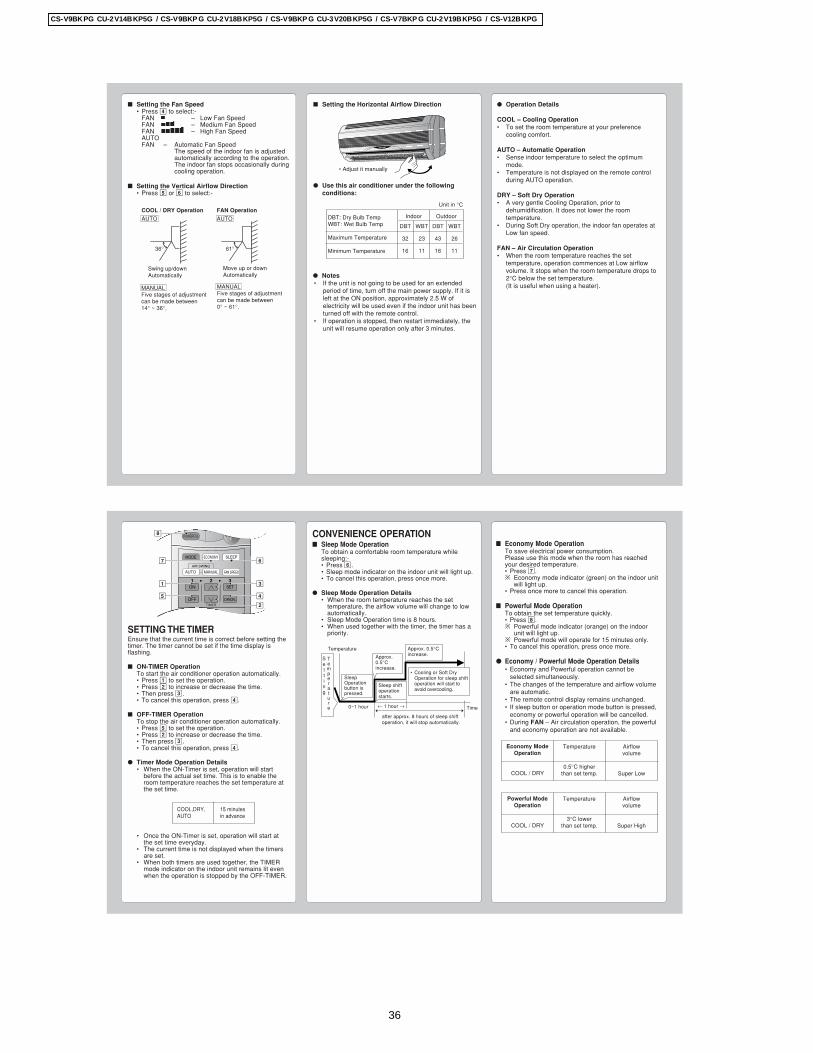
Operation Details
COOL – Cooling Operation• To set the room temperature at your preference
cooling comfort.
AUTO – Automatic Operation• Sense indoor temperature to select the optimum
mode.• Temperature is not displayed on the remote control
during AUTO operation.
DRY – Soft Dry Operation• A very gentle Cooling Operation, prior to
dehumidification. It does not lower the roomtemperature.
• During Soft Dry operation, the indoor fan operates atLow fan speed.
FAN – Air Circulation Operation• When the room temperature reaches the set
temperature, operation commences at Low airflowvolume. It stops when the room temperature drops to2°C below the set temperature.(It is useful when using a heater).
Setting the Fan Speed• Press 4 to select:-
FAN – Low Fan SpeedFAN – Medium Fan SpeedFAN – High Fan SpeedAUTOFAN – Automatic Fan Speed
The speed of the indoor fan is adjustedautomatically according to the operation.The indoor fan stops occasionally duringcooling operation.
Setting the Vertical Airflow Direction• Press 5 or 6 to select:-
Setting the Horizontal Airflow Direction
Use this air conditioner under the followingconditions:
• Adjust it manually
Notes• If the unit is not going to be used for an extended
period of time, turn off the main power supply. If it isleft at the ON position, approximately 2.5 W ofelectricity will be used even if the indoor unit has beenturned off with the remote control.
• If operation is stopped, then restart immediately, theunit will resume operation only after 3 minutes.
MANUALFive stages of adjustmentcan be made between14° ~ 36°.
Swing up/downAutomatically
Move up or downAutomatically
MANUALFive stages of adjustmentcan be made between0° ~ 61°.
36° 61°
COOL / DRY Operation
AUTO
FAN Operation
AUTO DBT: Dry Bulb TempWBT: Wet Bulb Temp
Maximum Temperature
Minimum Temperature
WBT
23
11
DBT
43
16
WBT
26
11
Indoor Outdoor
Unit in °C
DBT
32
16
SETTING THE TIMEREnsure that the current time is correct before setting thetimer. The timer cannot be set if the time display isflashing.
ON-TIMER OperationTo start the air conditioner operation automatically.• Press 1 to set the operation.• Press 2 to increase or decrease the time.• Then press 3.• To cancel this operation, press 4.
OFF-TIMER OperationTo stop the air conditioner operation automatically.• Press 5 to set the operation.• Press 2 to increase or decrease the time.• Then press 3.• To cancel this operation, press 4.
Timer Mode Operation Details• When the ON-Timer is set, operation will start
before the actual set time. This is to enable theroom temperature reaches the set temperature atthe set time.
• Once the ON-Timer is set, operation will start atthe set time everyday.
• The current time is not displayed when the timersare set.
• When both timers are used together, the TIMERmode indicator on the indoor unit remains lit evenwhen the operation is stopped by the OFF-TIMER.
CONVENIENCE OPERATION Sleep Mode Operation
To obtain a comfortable room temperature whilesleeping:-• Press 6.• Sleep mode indicator on the indoor unit will light up.• To cancel this operation, press once more.
Sleep Mode Operation Details• When the room temperature reaches the set
temperature, the airflow volume will change to lowautomatically.
• Sleep Mode Operation time is 8 hours.• When used together with the timer, the timer has a
priority.
Economy Mode OperationTo save electrical power consumption.Please use this mode when the room has reachedyour desired temperature.• Press 7.* Economy mode indicator (green) on the indoor unit
will light up.• Press once more to cancel this operation.
Powerful Mode OperationTo obtain the set temperature quickly.• Press 8.* Powerful mode indicator (orange) on the indoor
unit will light up.* Powerful mode will operate for 15 minutes only.• To cancel this operation, press once more.
Economy / Powerful Mode Operation Details• Economy and Powerful operation cannot be
selected simultaneously.• The changes of the temperature and airflow volume
are automatic.• The remote control display remains unchanged.• If sleep button or operation mode button is pressed,
economy or powerful operation will be cancelled.• During FAN – Air circulation operation, the powerful
and economy operation are not available.
CHECK RESET CLOCK
MODE SLEEPECONOMY
FAN SPEED
AIR SWING
OFF CANCEL
ON SET1 2 3
TIMER
OFF/ONPOWERFUL
AUTO MANUAL
3
6
4
1
7
5
2
8
Airflowvolume
Super Low
Economy ModeOperation
COOL / DRY
Temperature
0.5°C higherthan set temp.
Airflowvolume
Super High
Powerful ModeOperation
COOL / DRY
Temperature
3°C lowerthan set temp.
COOL,DRY, 15 minutesAUTO in advance
Time
Approx. 0.5°Cincrease.
Temperature
SleepOperationbutton ispressed.
Sleep shiftoperationstarts.
0~1 hour
after approx. 8 hours of sleep shiftoperation, it will stop automatically.
Approx.0.5°Cincrease.
• Cooling or Soft DryOperation for sleep shiftoperation will start toavoid overcooling.
Setting
Temperature ← 1 hour →
36
CS-V9BKPG CU-2V14BKP5G / CS-V9BKP G CU-2V18BKP5G / CS-V9BKP G CU-3V20BKP5G / CS-V7BKP G CU-2V19BKP5G / CS-V12BKPG
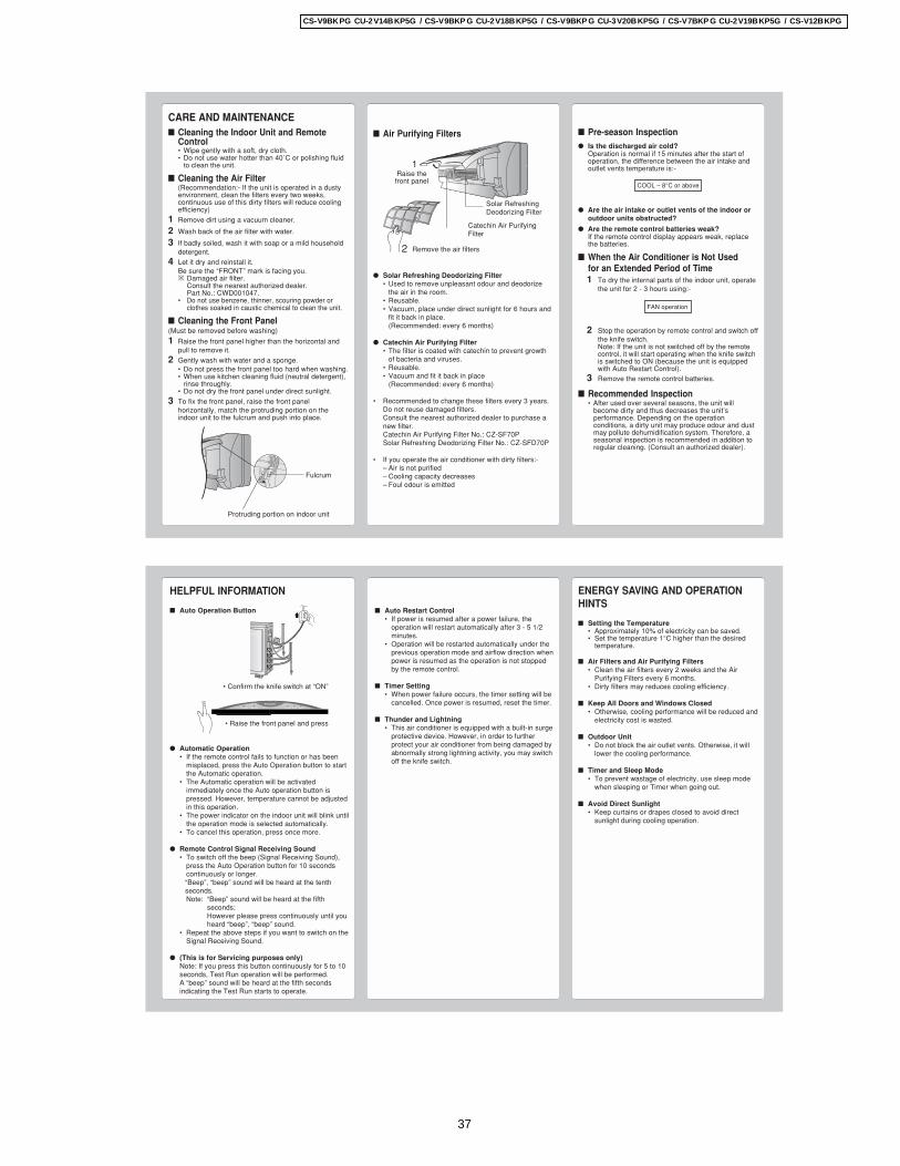
Pre-season Inspection Is the discharged air cold?
Operation is normal if 15 minutes after the start ofoperation, the difference between the air intake andoutlet vents temperature is:-
Are the air intake or outlet vents of the indoor oroutdoor units obstructed?
Are the remote control batteries weak?If the remote control display appears weak, replacethe batteries.
When the Air Conditioner is Not Usedfor an Extended Period of Time1 To dry the internal parts of the indoor unit, operate
the unit for 2 - 3 hours using:-
2 Stop the operation by remote control and switch offthe knife switch.Note: If the unit is not switched off by the remotecontrol, it will start operating when the knife switchis switched to ON (because the unit is equippedwith Auto Restart Control).
3 Remove the remote control batteries.
Recommended Inspection• After used over several seasons, the unit will
become dirty and thus decreases the unit’sperformance. Depending on the operationconditions, a dirty unit may produce odour and dustmay pollute dehumidification system. Therefore, aseasonal inspection is recommended in addition toregular cleaning. (Consult an authorized dealer).
CARE AND MAINTENANCE Cleaning the Indoor Unit and Remote
Control• Wipe gently with a soft, dry cloth.• Do not use water hotter than 40˚C or polishing fluid
to clean the unit.
Cleaning the Air Filter(Recommendation:- If the unit is operated in a dustyenvironment, clean the filters every two weeks,continuous use of this dirty filters will reduce coolingefficiency)
1 Remove dirt using a vacuum cleaner.
2 Wash back of the air filter with water.
3 If badly soiled, wash it with soap or a mild householddetergent.
4 Let it dry and reinstall it.Be sure the “FRONT” mark is facing you.* Damaged air filter.
Consult the nearest authorized dealer.Part No.: CWD001047.
• Do not use benzene, thinner, scouring powder orclothes soaked in caustic chemical to clean the unit.
Cleaning the Front Panel(Must be removed before washing)
1 Raise the front panel higher than the horizontal andpull to remove it.
2 Gently wash with water and a sponge.• Do not press the front panel too hard when washing.• When use kitchen cleaning fluid (neutral detergent),
rinse throughly.• Do not dry the front panel under direct sunlight.
3 To fix the front panel, raise the front panelhorizontally, match the protruding portion on theindoor unit to the fulcrum and push into place.
Air Purifying Filters
Solar Refreshing Deodorizing Filter• Used to remove unpleasant odour and deodorize
the air in the room.• Reusable.• Vacuum, place under direct sunlight for 6 hours and
fit it back in place.(Recommended: every 6 months)
Catechin Air Purifying Filter• The filter is coated with catechin to prevent growth
of bacteria and viruses.• Reusable.• Vacuum and fit it back in place
(Recommended: every 6 months)
• Recommended to change these filters every 3 years.Do not reuse damaged filters.Consult the nearest authorized dealer to purchase anew filter.Catechin Air Purifying Filter No.: CZ-SF70PSolar Refreshing Deodorizing Filter No.: CZ-SFD70P
• If you operate the air conditioner with dirty filters:-– Air is not purified– Cooling capacity decreases– Foul odour is emitted
Fulcrum
Protruding portion on indoor unit
COOL – 8°C or above
FAN operation
2 Remove the air filters
1Raise thefront panel
Catechin Air PurifyingFilter
Solar RefreshingDeodorizing Filter
HELPFUL INFORMATION
Auto Operation Button
Automatic Operation• If the remote control fails to function or has been
misplaced, press the Auto Operation button to startthe Automatic operation.
• The Automatic operation will be activatedimmediately once the Auto operation button ispressed. However, temperature cannot be adjustedin this operation.
• The power indicator on the indoor unit will blink untilthe operation mode is selected automatically.
• To cancel this operation, press once more.
Remote Control Signal Receiving Sound• To switch off the beep (Signal Receiving Sound),
press the Auto Operation button for 10 secondscontinuously or longer.“Beep”, “beep” sound will be heard at the tenthseconds.Note: “Beep” sound will be heard at the fifth
seconds;However please press continuously until youheard “beep”, “beep” sound.
• Repeat the above steps if you want to switch on theSignal Receiving Sound.
(This is for Servicing purposes only)Note: If you press this button continuously for 5 to 10seconds, Test Run operation will be performed.A “beep” sound will be heard at the fifth secondsindicating the Test Run starts to operate.
Auto Restart Control• If power is resumed after a power failure, the
operation will restart automatically after 3 - 5 1/2minutes.
• Operation will be restarted automatically under theprevious operation mode and airflow direction whenpower is resumed as the operation is not stoppedby the remote control.
Timer Setting• When power failure occurs, the timer setting will be
cancelled. Once power is resumed, reset the timer.
Thunder and Lightning• This air conditioner is equipped with a built-in surge
protective device. However, in order to furtherprotect your air conditioner from being damaged byabnormally strong lightning activity, you may switchoff the knife switch.
ENERGY SAVING AND OPERATIONHINTS
Setting the Temperature• Approximately 10% of electricity can be saved.• Set the temperature 1°C higher than the desired
temperature.
Air Filters and Air Purifying Filters• Clean the air filters every 2 weeks and the Air
Purifying Filters every 6 months.• Dirty filters may reduces cooling efficiency.
Keep All Doors and Windows Closed• Otherwise, cooling performance will be reduced and
electricity cost is wasted.
Outdoor Unit• Do not block the air outlet vents. Otherwise, it will
lower the cooling performance.
Timer and Sleep Mode• To prevent wastage of electricity, use sleep mode
when sleeping or Timer when going out.
Avoid Direct Sunlight• Keep curtains or drapes closed to avoid direct
sunlight during cooling operation.
POWERFULPOWERFULECONOMYECONOMY POWERPOWER TIMERTIMERSLEEPSLEEPPOWERFULPOWERFULECONOMYECONOMY POWERPOWER TIMERTIMERSLEEPSLEEP
• Raise the front panel and press
• Confirm the knife switch at “ON”
37
CS-V9BKPG CU-2V14BKP5G / CS-V9BKP G CU-2V18BKP5G / CS-V9BKP G CU-3V20BKP5G / CS-V7BKP G CU-2V19BKP5G / CS-V12BKPG
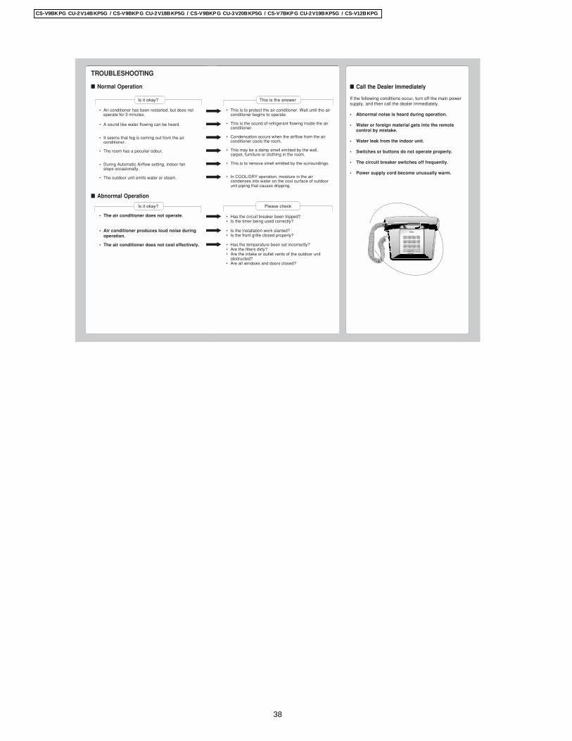
TROUBLESHOOTING
Normal Operation
Is it okay?
• Air conditioner has been restarted, but does notoperate for 3 minutes.
• A sound like water flowing can be heard.
• It seems that fog is coming out from the airconditioner.
• The room has a peculiar odour.
• During Automatic Airflow setting, indoor fanstops occasionally.
• The outdoor unit emits water or steam.
Abnormal Operation
Is it okay?
• The air conditioner does not operate.
• Air conditioner produces loud noise duringoperation.
• The air conditioner does not cool effectively.
This is the answer
• This is to protect the air conditioner. Wait until the airconditioner begins to operate.
• This is the sound of refrigerant flowing inside the airconditioner.
• Condensation occurs when the airflow from the airconditioner cools the room.
• This may be a damp smell emitted by the wall,carpet, furniture or clothing in the room.
• This is to remove smell emitted by the surroundings.
• In COOL/DRY operation, moisture in the aircondenses into water on the cool surface of outdoorunit piping that causes dripping.
Please check
• Has the circuit breaker been tripped?• Is the timer being used correctly?
• Is the installation work slanted?• Is the front grille closed properly?
• Has the temperature been set incorrectly?• Are the filters dirty?• Are the intake or outlet vents of the outdoor unit
obstructed?• Are all windows and doors closed?
Call the Dealer Immediately
If the following conditions occur, turn off the main powersupply, and then call the dealer immediately.
• Abnormal noise is heard during operation.
• Water or foreign material gets into the remotecontrol by mistake.
• Water leak from the indoor unit.
• Switches or buttons do not operate properly.
• The circuit breaker switches off frequently.
• Power supply cord become unusually warm.
38
CS-V9BKPG CU-2V14BKP5G / CS-V9BKP G CU-2V18BKP5G / CS-V9BKP G CU-3V20BKP5G / CS-V7BKP G CU-2V19BKP5G / CS-V12BKPG
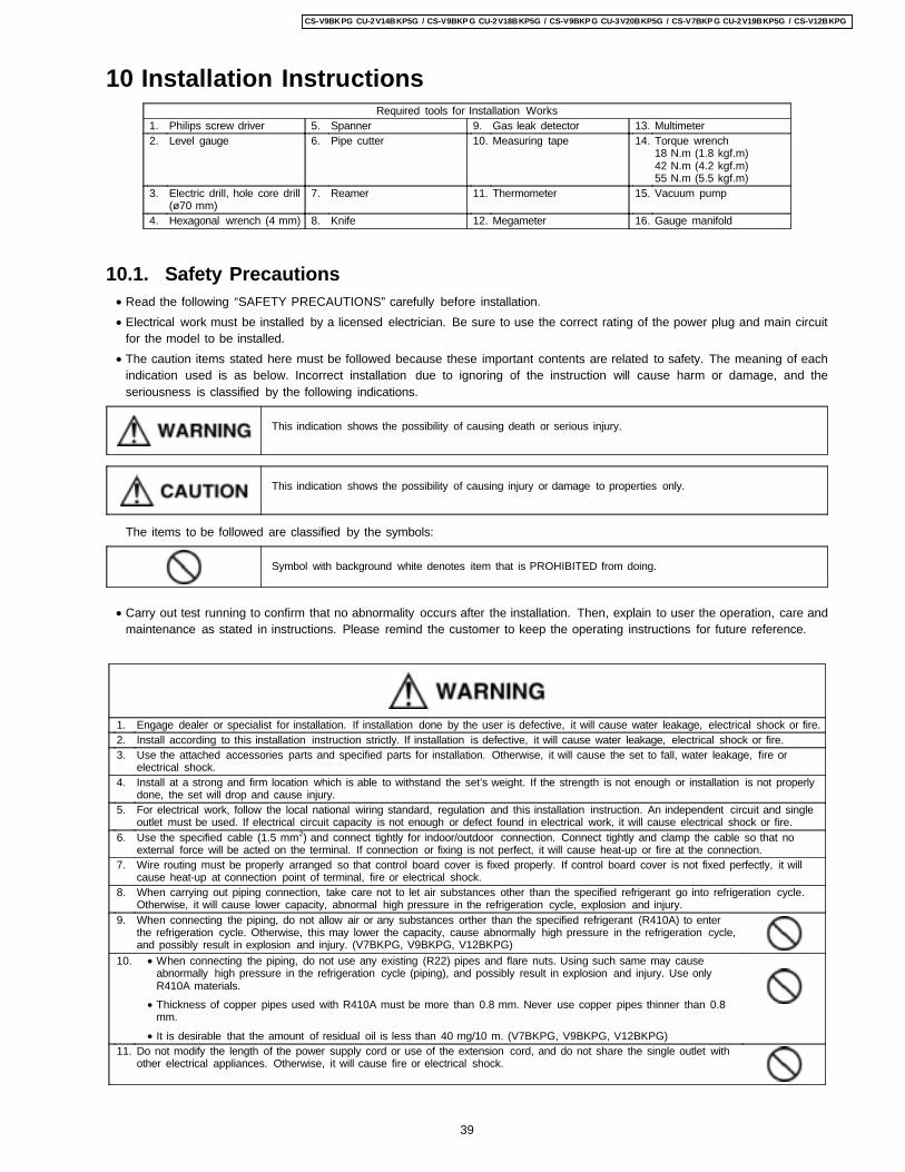
10 Installation InstructionsRequired tools for Installation Works
1. Philips screw driver 5. Spanner 9. Gas leak detector 13. Multimeter2. Level gauge 6. Pipe cutter 10. Measuring tape 14. Torque wrench
18 N.m (1.8 kgf.m)42 N.m (4.2 kgf.m)55 N.m (5.5 kgf.m)
3. Electric drill, hole core drill(ø70 mm)
7. Reamer 11. Thermometer 15. Vacuum pump
4. Hexagonal wrench (4 mm) 8. Knife 12. Megameter 16. Gauge manifold
10.1. Safety Precautions • Read the following “SAFETY PRECAUTIONS” carefully before installation. • Electrical work must be installed by a licensed electrician. Be sure to use the correct rating of the power plug and main circuit
for the model to be installed. • The caution items stated here must be followed because these important contents are related to safety. The meaning of each
indication used is as below. Incorrect installation due to ignoring of the instruction will cause harm or damage, and theseriousness is classified by the following indications.
This indication shows the possibility of causing death or serious injury.
This indication shows the possibility of causing injury or damage to properties only.
The items to be followed are classified by the symbols:
Symbol with background white denotes item that is PROHIBITED from doing.
• Carry out test running to confirm that no abnormality occurs after the installation. Then, explain to user the operation, care andmaintenance as stated in instructions. Please remind the customer to keep the operating instructions for future reference.
1. Engage dealer or specialist for installation. If installation done by the user is defective, it will cause water leakage, electrical shock or fire.2. Install according to this installation instruction strictly. If installation is defective, it will cause water leakage, electrical shock or fire.3. Use the attached accessories parts and specified parts for installation. Otherwise, it will cause the set to fall, water leakage, fire or
electrical shock.4. Install at a strong and firm location which is able to withstand the set’s weight. If the strength is not enough or installation is not properly
done, the set will drop and cause injury.5. For electrical work, follow the local national wiring standard, regulation and this installation instruction. An independent circuit and single
outlet must be used. If electrical circuit capacity is not enough or defect found in electrical work, it will cause electrical shock or fire.6. Use the specified cable (1.5 mm2) and connect tightly for indoor/outdoor connection. Connect tightly and clamp the cable so that no
external force will be acted on the terminal. If connection or fixing is not perfect, it will cause heat-up or fire at the connection.7. Wire routing must be properly arranged so that control board cover is fixed properly. If control board cover is not fixed perfectly, it will
cause heat-up at connection point of terminal, fire or electrical shock.8. When carrying out piping connection, take care not to let air substances other than the specified refrigerant go into refrigeration cycle.
Otherwise, it will cause lower capacity, abnormal high pressure in the refrigeration cycle, explosion and injury.9. When connecting the piping, do not allow air or any substances orther than the specified refrigerant (R410A) to enter
the refrigeration cycle. Otherwise, this may lower the capacity, cause abnormally high pressure in the refrigeration cycle,and possibly result in explosion and injury. (V7BKPG, V9BKPG, V12BKPG)
10. • When connecting the piping, do not use any existing (R22) pipes and flare nuts. Using such same may causeabnormally high pressure in the refrigeration cycle (piping), and possibly result in explosion and injury. Use onlyR410A materials.
• Thickness of copper pipes used with R410A must be more than 0.8 mm. Never use copper pipes thinner than 0.8mm.
• It is desirable that the amount of residual oil is less than 40 mg/10 m. (V7BKPG, V9BKPG, V12BKPG)11. Do not modify the length of the power supply cord or use of the extension cord, and do not share the single outlet with
other electrical appliances. Otherwise, it will cause fire or electrical shock.
39
CS-V9BKPG CU-2V14BKP5G / CS-V9BKP G CU-2V18BKP5G / CS-V9BKP G CU-3V20BKP5G / CS-V7BKP G CU-2V19BKP5G / CS-V12BKPG
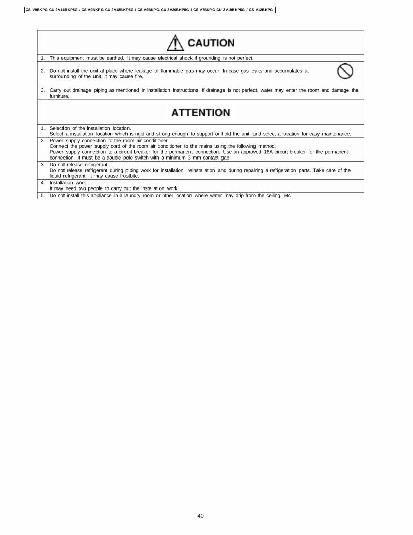
1. This equipment must be earthed. It may cause electrical shock if grounding is not perfect.
2. Do not install the unit at place where leakage of flammable gas may occur. In case gas leaks and accumulates atsurrounding of the unit, it may cause fire.
3. Carry out drainage piping as mentioned in installation instructions. If drainage is not perfect, water may enter the room and damage thefurniture.
1. Selection of the installation location.Select a installation location which is rigid and strong enough to support or hold the unit, and select a location for easy maintenance.
2. Power supply connection to the room air conditioner.Connect the power supply cord of the room air conditioner to the mains using the following method.Power supply connection to a circuit breaker for the permanent connection. Use an approved 16A circuit breaker for the permanentconnection. It must be a double pole switch with a minimum 3 mm contact gap.
3. Do not release refrigerant.Do not release refrigerant during piping work for installation, reinstallation and during repairing a refrigeration parts. Take care of theliquid refrigerant, it may cause frostbite.
4. Installation work.It may need two people to carry out the installation work.
5. Do not install this appliance in a laundry room or other location where water may drip from the ceiling, etc.
40
CS-V9BKPG CU-2V14BKP5G / CS-V9BKP G CU-2V18BKP5G / CS-V9BKP G CU-3V20BKP5G / CS-V7BKP G CU-2V19BKP5G / CS-V12BKPG
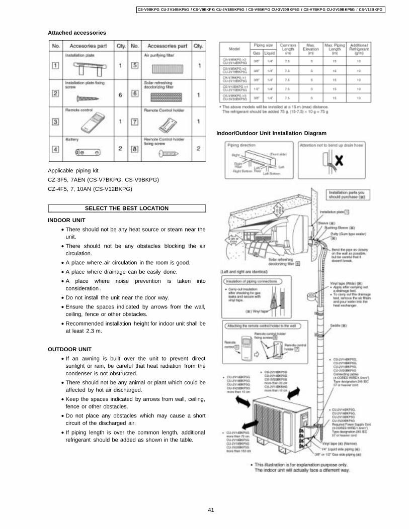
Applicable piping kitCZ-3F5, 7AEN (CS-V7BKPG, CS-V9BKPG)CZ-4F5, 7, 10AN (CS-V12BKPG)
SELECT THE BEST LOCATION
INDOOR UNIT • There should not be any heat source or steam near the
unit. • There should not be any obstacles blocking the air
circulation. • A place where air circulation in the room is good. • A place where drainage can be easily done. • A place where noise prevention is taken into
consideration . • Do not install the unit near the door way. • Ensure the spaces indicated by arrows from the wall,
ceiling, fence or other obstacles. • Recommended installation height for indoor unit shall be
at least 2.3 m.
OUTDOOR UNIT • If an awning is built over the unit to prevent direct
sunlight or rain, be careful that heat radiation from thecondenser is not obstructed.
• There should not be any animal or plant which could beaffected by hot air discharged.
• Keep the spaces indicated by arrows from wall, ceiling,fence or other obstacles.
• Do not place any obstacles which may cause a shortcircuit of the discharged air.
• If piping length is over the common length, additionalrefrigerant should be added as shown in the table.
Indoor/Outdoor Unit Installation Diagram
Attached accessories
41
CS-V9BKPG CU-2V14BKP5G / CS-V9BKP G CU-2V18BKP5G / CS-V9BKP G CU-3V20BKP5G / CS-V7BKP G CU-2V19BKP5G / CS-V12BKPG
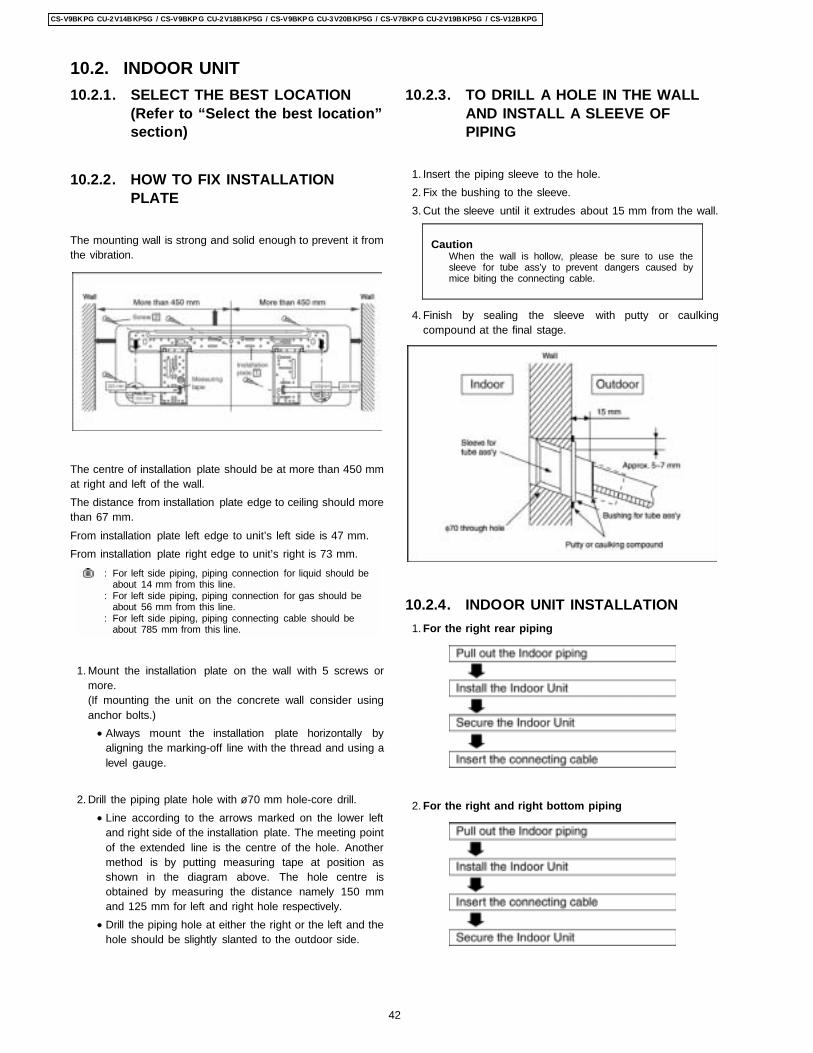
10.2.1. SELECT THE BEST LOCATION(Refer to “Select the best location”section)
10.2.2. HOW TO FIX INSTALLATIONPLATE
The mounting wall is strong and solid enough to prevent it fromthe vibration.
The centre of installation plate should be at more than 450 mmat right and left of the wall.The distance from installation plate edge to ceiling should morethan 67 mm.From installation plate left edge to unit’s left side is 47 mm.From installation plate right edge to unit’s right is 73 mm.
:
:
:
For left side piping, piping connection for liquid should beabout 14 mm from this line.For left side piping, piping connection for gas should beabout 56 mm from this line.For left side piping, piping connecting cable should beabout 785 mm from this line.
1. Mount the installation plate on the wall with 5 screws ormore.(If mounting the unit on the concrete wall consider usinganchor bolts.) • Always mount the installation plate horizontally by
aligning the marking-off line with the thread and using alevel gauge.
2. Drill the piping plate hole with ø70 mm hole-core drill. • Line according to the arrows marked on the lower left
and right side of the installation plate. The meeting pointof the extended line is the centre of the hole. Anothermethod is by putting measuring tape at position asshown in the diagram above. The hole centre isobtained by measuring the distance namely 150 mmand 125 mm for left and right hole respectively.
• Drill the piping hole at either the right or the left and thehole should be slightly slanted to the outdoor side.
10.2.3. TO DRILL A HOLE IN THE WALLAND INSTALL A SLEEVE OFPIPING
1. Insert the piping sleeve to the hole. 2. Fix the bushing to the sleeve. 3. Cut the sleeve until it extrudes about 15 mm from the wall.
CautionWhen the wall is hollow, please be sure to use thesleeve for tube ass’y to prevent dangers caused bymice biting the connecting cable.
4. Finish by sealing the sleeve with putty or caulkingcompound at the final stage.
10.2.4. INDOOR UNIT INSTALLATION 1. For the right rear piping
2. For the right and right bottom piping
10.2. INDOOR UNIT
42
CS-V9BKPG CU-2V14BKP5G / CS-V9BKP G CU-2V18BKP5G / CS-V9BKP G CU-3V20BKP5G / CS-V7BKP G CU-2V19BKP5G / CS-V12BKPG
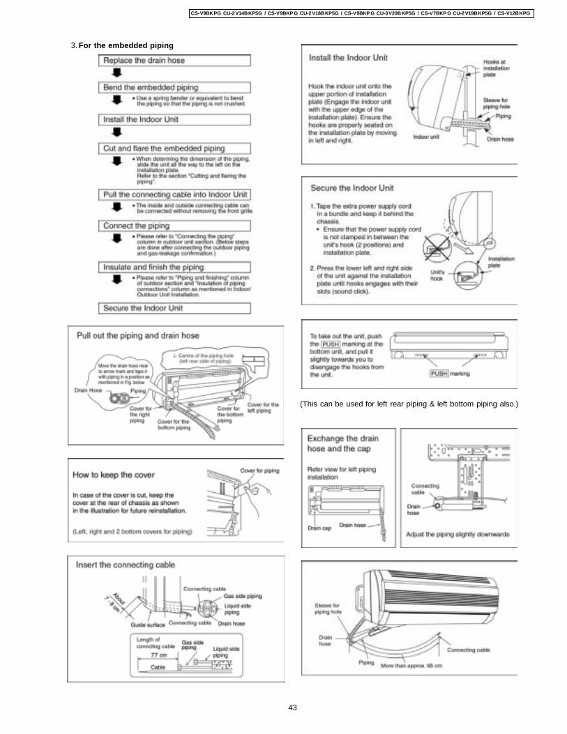
3. For the embedded piping
(This can be used for left rear piping & left bottom piping also.)
43
CS-V9BKPG CU-2V14BKP5G / CS-V9BKP G CU-2V18BKP5G / CS-V9BKP G CU-3V20BKP5G / CS-V7BKP G CU-2V19BKP5G / CS-V12BKPG
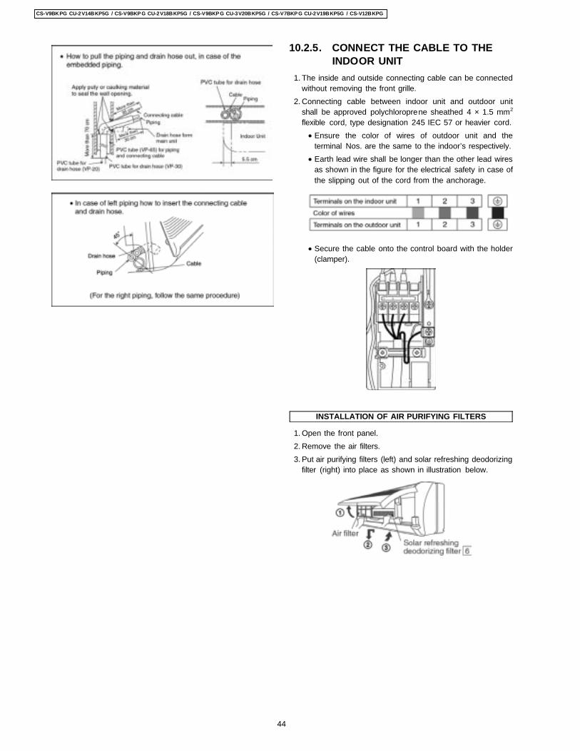
10.2.5. CONNECT THE CABLE TO THEINDOOR UNIT
1. The inside and outside connecting cable can be connectedwithout removing the front grille.
2. Connecting cable between indoor unit and outdoor unitshall be approved polychloroprene sheathed 4 × 1.5 mm2
flexible cord, type designation 245 IEC 57 or heavier cord. • Ensure the color of wires of outdoor unit and the
terminal Nos. are the same to the indoor’s respectively. • Earth lead wire shall be longer than the other lead wires
as shown in the figure for the electrical safety in case ofthe slipping out of the cord from the anchorage.
• Secure the cable onto the control board with the holder(clamper).
INSTALLATION OF AIR PURIFYING FILTERS
1. Open the front panel. 2. Remove the air filters. 3. Put air purifying filters (left) and solar refreshing deodorizing
filter (right) into place as shown in illustration below.
44
CS-V9BKPG CU-2V14BKP5G / CS-V9BKP G CU-2V18BKP5G / CS-V9BKP G CU-3V20BKP5G / CS-V7BKP G CU-2V19BKP5G / CS-V12BKPG
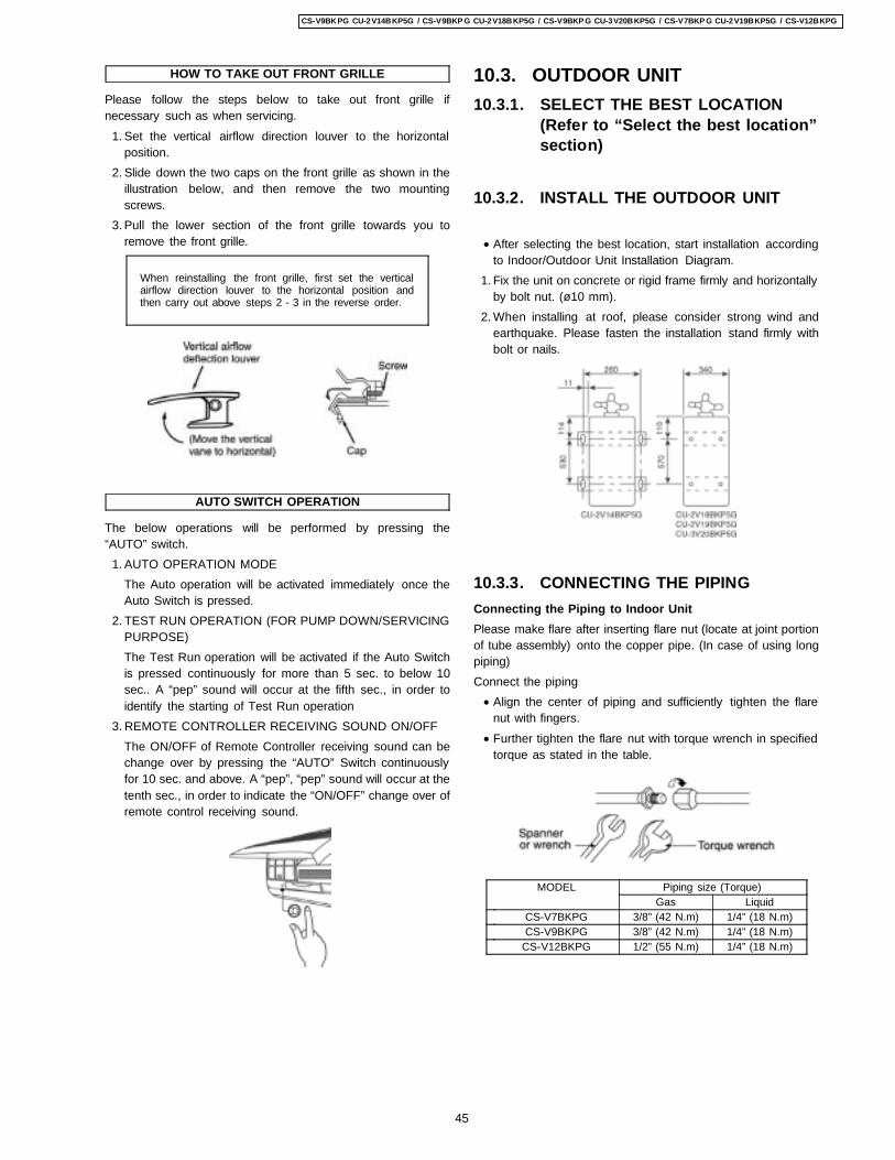
HOW TO TAKE OUT FRONT GRILLE
Please follow the steps below to take out front grille ifnecessary such as when servicing. 1. Set the vertical airflow direction louver to the horizontal
position. 2. Slide down the two caps on the front grille as shown in the
illustration below, and then remove the two mountingscrews.
3. Pull the lower section of the front grille towards you toremove the front grille.
When reinstalling the front grille, first set the verticalairflow direction louver to the horizontal position andthen carry out above steps 2 - 3 in the reverse order.
AUTO SWITCH OPERATION
The below operations will be performed by pressing the“AUTO” switch. 1. AUTO OPERATION MODE
The Auto operation will be activated immediately once theAuto Switch is pressed.
2. TEST RUN OPERATION (FOR PUMP DOWN/SERVICINGPURPOSE)The Test Run operation will be activated if the Auto Switchis pressed continuously for more than 5 sec. to below 10sec.. A “pep” sound will occur at the fifth sec., in order toidentify the starting of Test Run operation
3. REMOTE CONTROLLER RECEIVING SOUND ON/OFFThe ON/OFF of Remote Controller receiving sound can bechange over by pressing the “AUTO” Switch continuouslyfor 10 sec. and above. A “pep”, “pep” sound will occur at thetenth sec., in order to indicate the “ON/OFF” change over ofremote control receiving sound.
10.3. OUTDOOR UNIT10.3.1. SELECT THE BEST LOCATION
(Refer to “Select the best location”section)
10.3.2. INSTALL THE OUTDOOR UNIT
• After selecting the best location, start installation accordingto Indoor/Outdoor Unit Installation Diagram.
1. Fix the unit on concrete or rigid frame firmly and horizontallyby bolt nut. (ø10 mm).
2. When installing at roof, please consider strong wind andearthquake. Please fasten the installation stand firmly withbolt or nails.
10.3.3. CONNECTING THE PIPINGConnecting the Piping to Indoor UnitPlease make flare after inserting flare nut (locate at joint portionof tube assembly) onto the copper pipe. (In case of using longpiping)Connect the piping • Align the center of piping and sufficiently tighten the flare
nut with fingers. • Further tighten the flare nut with torque wrench in specified
torque as stated in the table.
MODEL Piping size (Torque)Gas Liquid
CS-V7BKPG 3/8” (42 N.m) 1/4” (18 N.m)CS-V9BKPG 3/8” (42 N.m) 1/4” (18 N.m)
CS-V12BKPG 1/2” (55 N.m) 1/4” (18 N.m)
45
CS-V9BKPG CU-2V14BKP5G / CS-V9BKP G CU-2V18BKP5G / CS-V9BKP G CU-3V20BKP5G / CS-V7BKP G CU-2V19BKP5G / CS-V12BKPG
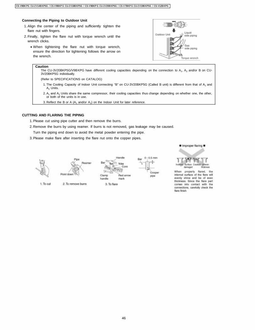
Connecting the Piping to Outdoor Unit 1. Align the center of the piping and sufficiently tighten the
flare nut with fingers. 2. Finally, tighten the flare nut with torque wrench until the
wrench clicks. • When tightening the flare nut with torque wrench,
ensure the direction for tightening follows the arrow onthe wrench.
CautionThe CU-3V20BKP5G/V9BKPG have different cooling capacities depending on the connection to A1, A2 and/or B on CU-3V20BKP5G individually.
(Refer to SPECIFICATIONS on CATALOG)
1. The Cooling Capacity of Indoor Unit connecting “B” on CU-3V20BKP5G (Called B unit) is different from that of A1 andA2 Units.
2. A1 and A2 Units share the same compressor, their cooling capacities thus change depending on whether one, the other,or both of the units is in use.
3. Reflect the B or A (A1 and/or A2) on the Indoor Unit for later reference.
CUTTING AND FLARING THE PIPING 1. Please cut using pipe cutter and then remove the burrs. 2. Remove the burrs by using reamer. If burrs is not removed, gas leakage may be caused.
Turn the piping end down to avoid the metal powder entering the pipe. 3. Please make flare after inserting the flare nut onto the copper pipes.
46
CS-V9BKPG CU-2V14BKP5G / CS-V9BKP G CU-2V18BKP5G / CS-V9BKP G CU-3V20BKP5G / CS-V7BKP G CU-2V19BKP5G / CS-V12BKPG
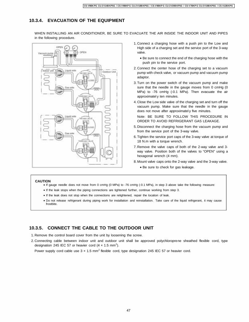
1. Connect a charging hose with a push pin to the Low andHigh side of a charging set and the service port of the 3-wayvalve. • Be sure to connect the end of the charging hose with the
push pin to the service port. 2. Connect the center hose of the charging set to a vacuum
pump with check valve, or vacuum pump and vacuum pumpadaptor.
3. Turn on the power switch of the vacuum pump and makesure that the needle in the gauge moves from 0 cmHg (0MPa) to -76 cmHg (-0.1 MPa). Then evacuate the airapproximatel y ten minutes.
4. Close the Low side valve of the charging set and turn off thevacuum pump. Make sure that the needle in the gaugedoes not move after approximatel y five minutes.Note: BE SURE TO FOLLOW THIS PROCEDURE INORDER TO AVOID REFRIGERANT GAS LEAKAGE.
5. Disconnect the charging hose from the vacuum pump andfrom the service port of the 3-way valve.
6. Tighten the service port caps of the 3-way valve at torque of18 N.m with a torque wrench.
7. Remove the valve caps of both of the 2-way valve and 3-way valve. Position both of the valves to “OPEN” using ahexagonal wrench (4 mm).
8. Mount valve caps onto the 2-way valve and the 3-way valve. • Be sure to check for gas leakage.
10.3.4. EVACUATION OF THE EQUIPMENT
WHEN INSTALLING AN AIR CONDITIONER, BE SURE TO EVACUATE THE AIR INSIDE THE INDOOR UNIT AND PIPESin the following procedure.
CAUTION • If gauge needle does not move from 0 cmHg (0 MPa) to -76 cmHg (-0.1 MPa), in step 3 above take the following measure:
• If the leak stops when the piping connections are tightened further, continue working from step 3.
• If the leak does not stop when the connections are retightened, repair the location of leak.
• Do not release refrigerant during piping work for installation and reinstallation. Take care of the liquid refrigerant, it may causefrostbite.
10.3.5. CONNECT THE CABLE TO THE OUTDOOR UNIT 1. Remove the control board cover from the unit by loosening the screw. 2. Connecting cable between indoor unit and outdoor unit shall be approved polychloroprene sheathed flexible cord, type
designation 245 IEC 57 or heavier cord (4 × 1.5 mm2).Power supply cord cable use 3 × 1.5 mm2 flexible cord, type designation 245 IEC 57 or heavier cord.
47
CS-V9BKPG CU-2V14BKP5G / CS-V9BKP G CU-2V18BKP5G / CS-V9BKP G CU-3V20BKP5G / CS-V7BKP G CU-2V19BKP5G / CS-V12BKPG
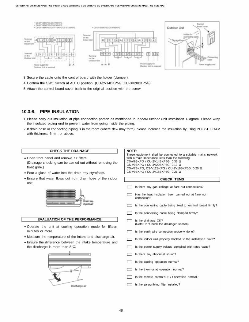
CHECK THE DRAINAGE
• Open front panel and remove air filters.(Drainage checking can be carried out without removing thefront grille.)
• Pour a glass of water into the drain tray-styrofoam. • Ensure that water flows out from drain hose of the indoor
unit.
EVALUATION OF THE PERFORMANCE
• Operate the unit at cooling operation mode for fifteenminutes or more.
• Measure the temperature of the intake and discharge air. • Ensure the difference between the intake temperature and
the discharge is more than 8°C.
NOTE:These equipment shall be connected to a suitable mains networkwith a main impedance less than the following:CS-V9BKPG / CU-2V14BKP5G: 0.35 ΩCS-V9BKPG / CU-3V20BKP5G: 0.19 ΩCS-V7BKPG, CS-V12BKPG / CU-2V19BKP5G: 0.20 ΩCS-V9BKPG / CU-2V18BKP5G: 0.21 Ω
CHECK ITEMS
Is there any gas leakage at flare nut connections?
Has the heat insulation been carried out at flare nutconnection?
Is the connecting cable being fixed to terminal board firmly?
Is the connecting cable being clamped firmly?
Is the drainage OK?(Refer to “Check the drainage” section)
Is the earth wire connection properly done?
Is the indoor unit properly hooked to the installation plate?
Is the power supply voltage complied with rated value?
Is there any abnormal sound?
Is the cooling operation normal?
Is the thermostat operation normal?
Is the remote control’s LCD operation normal?
Is the air purifying filter installed?
3. Secure the cable onto the control board with the holder (clamper). 4. Confirm the SW1 Switch at AUTO position. (CU-2V14BKP5G, CU-3V20BKP5G) 5. Attach the control board cover back to the original position with the screw.
10.3.6. PIPE INSULATION 1. Please carry out insulation at pipe connection portion as mentioned in Indoor/Outdoor Unit Installation Diagram. Please wrap
the insulated piping end to prevent water from going inside the piping. 2. If drain hose or connecting piping is in the room (where dew may form), please increase the insulation by using POLY-E FOAM
with thickness 6 mm or above.
48
CS-V9BKPG CU-2V14BKP5G / CS-V9BKP G CU-2V18BKP5G / CS-V9BKP G CU-3V20BKP5G / CS-V7BKP G CU-2V19BKP5G / CS-V12BKPG
11 Installation and Servicing Air Conditioner Using R410A11.1. OUTLINE11.1.1. About R410A Refrigerant 1. Converting air conditioners to R410A
Since it was declared in1974 that chlorofluorocarbons (CFC), hydro chlorofluorocarbons (HCFC) and other substances pose adestructive danger to the ozone layer in the earth´s upper stratosphere (20 to 40 km above the earth), measures have beentaken around the world to prevent this destruction.The R22 refrigerant which has conventional ly been used in ACs is an HCFC refrigerant and, therefore, possesses this ozone-destroying potential. International regulations (the Montreal Protocol Ozone-Damaging Substances) and the domestic laws ofvarious countries call for the early substitution of R22 by a refrigerant which will not harm the ozone layer. • In ACs, the HFC refrigerant which has become the mainstream alternative called R410A.Compared with R22, the pressure
of R410A is approximatel y 1.6 times as high at the same refrigerant temperature, but the energy efficiency is about thesame. Consisting of hydrogen (H), fluorine (F) and carbon (C), R410A is an HFC refrigerant. Another typical HFC refrigerantis R407C. While the energy efficiency of R407C is some what inferior to that of R410A, it offers the advantage of havingpressure characteristic s which are about the same as those of R22, and is used mainly in packaged ACs.
2. The characteristic s of HFC (R410A) refrigerants a. Chemical characteristic s
The chemical characteristic s of R410A are similar to those of R22 in that both are chemically stable, non-flammablerefrigerants with low toxicity.However, just like R22, the specific gravity of R410A gas is heavier than that of air. Because of this, it can cause an oxygendeficiency if it leaks into a closed room since it collects in the lower area of the room. It also generates toxic gas when it isdirectly exposed to a flame, so it must be used in a well ventilated environment where it will not collect.
Table 1 Physical comparison of R410A and R22R410A R22
Composition (wt%) R32/R125 (50/50) R22 (100)Boiling point (°C) -51.4 -40.8Vaporizing pressure (25°C) 1.56 Mpa (15.9 kgf/cm2) 0.94 Mpa (9.6 kgf/cm2)Saturated vapor density 64.0 kg/m3 44.4 kg/m3
Flammability Non-flammable Non-flammableOzone-destroying point (ODP) 0 0.005Global-warming point (GWP) 1730 1700
b. Compositional change (pseudo-azeotropic characteristic s)R410A is a pseudo-azeotropic mixture comprising the two components R32 and R125. Multi-component refrigerants withthese chemical characteristic s exhibit little compositional change even from phase changes due to vaporization 9orcondensation), which means that there is little change in the circulating refrigerant composition even when the refrigerantleaks from the gaseous section of the piping.Accordingly, R410A can be handled in almost the same manner as the single-component refrigerant R22. However, whencharging, because there is a slight change in composition between the gas phase and the liquid phase inside a cylinder orother container, charging should basically begin with the liquid side.
c. Pressure characteristic sAs seen in Table 2, the gas pressure of R410A is approximatel y 1.6 times as high as that of R22 at the same refrigeranttemperature, which means that special R410A tools and materials with high-pressure specifications must be used for allrefrigerant piping work and servicing.
Table 2 Comparison of R410A and R22 saturated vapor densityUnit: MPa
Refrigerant Temperature (°C) R410A R22-20 0.30 0.140 0.70 0.40
20 1.35 0.8140 2.32 1.4360 3.73 2.3365 4.15 2.60
49
CS-V9BKPG CU-2V14BKP5G / CS-V9BKP G CU-2V18BKP5G / CS-V9BKP G CU-3V20BKP5G / CS-V7BKP G CU-2V19BKP5G / CS-V12BKPG
d. R410A refrigerating machine oilConventionally, mineral oil or a synthetic oil such as alkylbenzene has been used for R22 refrigerating machine oil. Becauseof the poor compatibility between R410A and conventional oils like mineral oil, however, there is a tendency for therefrigerating machine oil to collect in the refrigerating cycle. For this reason, polyester and other synthetic oils which havea high compatibility with R410A are used as refrigerating machine oil.Because of the high hygroscopic property of synthetic oil, more care must be taken in its handling than was necessary withconventional refrigerating machine oils. Also, these synthetic oils will degrade if mixed with mineral oil or alkylbenzene ,causing clogging in capillary tubes or compressor malfunction. Do not mix them under any circumstances.
11.1.2. Safety Measure When Installing / Receiving Refrigerant PipingCause the gas pressure of R410A is approximatel y 1.6 times as high as that of R22, a mistake in installation or servicing couldresult in a major accident. It is essential that you use R410a tools and materials, and that you observe the following precautionsto ensure safety. 1. Do not use any refrigerant other than R410A in ACs that have been used with R410A. 2. If any refrigerant gas leaks while you are working, ventilate the room. Toxic gas may be generated if refrigerant gas is exposed
to a direct flame. 3. When installing or transferring an AC, do not allow any air or substance other than R410A to mix into the refrigeration cycle. If
it does, the pressure in the refrigeration cycle can become abnormally high, possibly causing an explosion and/or injury. 4. After finishing the installation, check to make sure there is no refrigerant gas leaking. 5. When installing or transferring an AC, follow the instructions in the installation instructions carefully. Incorrect installation can
result in an abnormal refrigeration cycle or water leakage, electric shock, fire, etc. 6. Do not perform any alterations on the AC unit under any circumstances. Have all repair work done by a specialist. Incorrect
repairs can result in an water leakage, electric shock, fire, etc.
11.2. TOOL FOR INSTALLING / SERVICING REFRIGERANT PIPING
11.2.1. Necessary ToolsIn order to prevent an R410A AC from mistakenly being charged with any other refrigerant, the diameter of the 3-way valve serviceport on the outdoor unit has been changed. Also, to increase its ability to withstand pressure, the opposing dimensions have beenchanged for the refrigerant pipe flaring size and flare nut. Accordingly, when installing or servicing refrigerant piping, you must haveboth the R410A and ordinary tools listed below.
Table 3 Tools for installation, transferring or replacementType of work Ordinary tools R410A tools
Flaring Flaring tool (clutch type), pipe cutter,reamer
Copper pipe gauge for clearanceAdjustment, flaring tool (clutch type)*1)
Bending, connecting pipes Torque wrench (nominal diameter 1/4,3/8,1/2) Fixed spanner (opposing sides 12mm, 17 mm, 19 mm) Adjustable wrench,Spring bender
Air purging Vacuum pump Hexagonal wrench(opposing sides 4 mm)
Manifold gauge, charging hose, vacuumpump adaptor
Gas leak inspection Gas leak inspection fluid or soapy water Electric gas leak detector for HFCrefrigerant*2)
*1) You can use the conventional (R22) flaring tool. If you need to buy a new tool, buy the R410A type.*2) Use when it is necessary to detect small gas leaks.For other installation work, you should have the usual tools, such as screwdrivers (+,-), a metal-cutting saw, an electrical drill, a holecore drill (65 or 70 dia.), a tape measure, a level, a thermometer, a clamp meter, an insulation tester, a voltmeter, etc.
Table 4 Tools for servingType of work Ordinary tools R410A tools
Refrigerant charging Electronic scale for refrigerant chargingRefrigerant cylinder Charging orifice andpacking for refrigerant cylinder
Brazing (Replacing refrigerating cyclepart*1)
Nitrogen blow set (be sure to use nitrogenblowing for all brazing), and brazing), andbrazing machine
*1) Always replace the dryer of the outdoor unit at the same time. The replacement dryer is wrapped in a vacuum pack. Replaceit last among the refrigerating cycle parts. Start brazing as soon as you have opened the vacuum pack, and begin the vacuumingoperation within 2 hours.
50
CS-V9BKPG CU-2V14BKP5G / CS-V9BKP G CU-2V18BKP5G / CS-V9BKP G CU-3V20BKP5G / CS-V7BKP G CU-2V19BKP5G / CS-V12BKPG
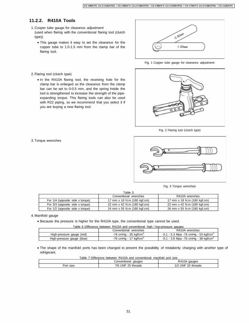
11.2.2. R410A Tools 1. Cooper tube gauge for clearance adjustment
(used when flaring with the conventional flaring tool (clutchtype)) • This gauge makes it easy to set the clearance for the
copper tube to 1.0-1.5 mm from the clamp bar of theflaring tool.
2. Flaring tool (clutch type) • In the R410A flaring tool, the receiving hole for the
clamp bar is enlarged so the clearance from the clampbar can be set to 0-0.5 mm, and the spring inside thetool is strengthened to increase the strength of the pipe-expanding torque. This flaring tools can also be usedwith R22 piping, so we recommend that you select it ifyou are buying a new flaring tool.
3. Torque wrenches
4. Manifold gauge
Fig. 1 Copper tube gauge for clearance adjustment
Fig. 2 Flaring tool (clutch type)
Fig. 3 Torque wrenches
Table 5Conventional wrenches R410A wrenches
For 1/4 (opposite side x torque) 17 mm x 18 N.m (180 kgf.cm) 17 mm x 18 N.m (180 kgf.cm)For 3/3 (opposite side x torque) 22 mm x 42 N.m (180 kgf.cm) 22 mm x 42 N.m (180 kgf.cm)For 1/2 (opposite side x torque) 24 mm x 55 N.m (180 kgf.cm) 26 mm x 55 N.m (180 kgf.cm)
• Because the pressure is higher for the R410A type, the conventional type cannot be used.Table 6 Difference between R410A and conventional high / low-pressure gauges
Conventional wrenches R410A wrenchesHigh-pressure gauge (red) -76 cmHg - 35 kgf/cm3 -0.1 - 5.3 Mpa -76 cmHg - 53 kgf/cm3
High-pressure gauge (blue) -76 cmHg - 17 kgf/cm3 -0.1 - 3.8 Mpa -76 cmHg - 38 kgf/cm3
• The shape of the manifold ports has been changed to prevent the possibility of mistakenly charging with another type ofrefrigerant.
Table 7 Difference between R410A and conventional manifold port sizeConventional gauges R410A gauges
Port size 7/6 UNF 20 threads 1/2 UNF 20 threads
51
CS-V9BKPG CU-2V14BKP5G / CS-V9BKP G CU-2V18BKP5G / CS-V9BKP G CU-3V20BKP5G / CS-V7BKP G CU-2V19BKP5G / CS-V12BKPG
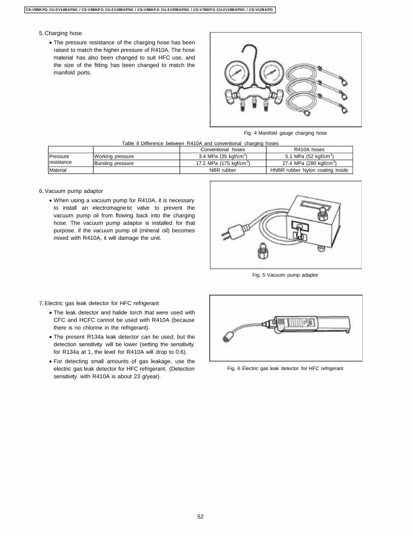
5. Charging hose • The pressure resistance of the charging hose has been
raised to match the higher pressure of R410A. The hosematerial has also been changed to suit HFC use, andthe size of the fitting has been changed to match themanifold ports.
6. Vacuum pump adaptor • When using a vacuum pump for R410A, it is necessary
to install an electromagne tic valve to prevent thevacuum pump oil from flowing back into the charginghose. The vacuum pump adaptor is installed for thatpurpose. if the vacuum pump oil (mineral oil) becomesmixed with R410A, it will damage the unit.
7. Electric gas leak detector for HFC refrigerant • The leak detector and halide torch that were used with
CFC and HCFC cannot be used with R410A (becausethere is no chlorine in the refrigerant).
• The present R134a leak detector can be used, but thedetection sensitivity will be lower (setting the sensitivityfor R134a at 1, the level for R410A will drop to 0.6).
• For detecting small amounts of gas leakage, use theelectric gas leak detector for HFC refrigerant. (Detectionsensitivity with R410A is about 23 g/year).
Fig. 4 Manifold gauge charging hose
Fig. 5 Vacuum pump adaptor
Fig. 6 Electric gas leak detector for HFC refrigerant
Table 8 Difference between R410A and conventional charging hosesConventional hoses R410A hoses
Pressureresistance
Working pressure 3.4 MPa (35 kgf/cm3) 5.1 MPa (52 kgf/cm3)Bursting pressure 17.2 MPa (175 kgf/cm3) 27.4 MPa (280 kgf/cm3)
Material NBR rubber HNBR rubber Nylon coating inside
52
CS-V9BKPG CU-2V14BKP5G / CS-V9BKP G CU-2V18BKP5G / CS-V9BKP G CU-3V20BKP5G / CS-V7BKP G CU-2V19BKP5G / CS-V12BKPG
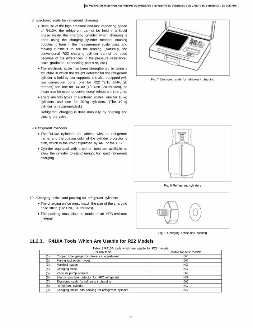
8. Electronic scale for refrigerant charging • Because of the high pressure and fast vaporizing speed
of R410A, the refrigerant cannot be held in a liquidphase inside the charging cylinder when charging isdone using the charging cylinder method, causingbubbles to form in the measuremen t scale glass andmaking it difficult to see the reading. (Naturally, theconventional R22 charging cylinder cannot be usedbecause of the differences in the pressure resistance,scale gradation, connecting port size, etc.)
• The electronic scale has been strengthened by using astructure in which the weight detector for the refrigerantcylinder is held by four supports. It is also equipped withtwo connection ports, one for R22 *7/16 UNF, 20threads) and one for R410A (1/2 UNF, 20 threads), soit can also be used for conventional refrigerant charging.
• There are two types of electronic scales, one for 10-kgcylinders and one for 20-kg cylinders. (The 10-kgcylinder is recommended.)Refrigerant charging is done manually by opening andclosing the valve.
9. Refrigerant cylinders • The R410A cylinders are labeled with the refrigerant
name, and the coating color of the cylinder protector ispink, which is the color stipulated by ARI of the U.S.
• Cylinder equipped with a siphon tube are available toallow the cylinder to stand upright for liquid refrigerantcharging.
10. Charging orifice and packing for refrigerant cylinders • The charging orifice must match the size of the charging
hose fitting (1/2 UNF, 20 threads). • The packing must also be made of an HFC-resistant
material.
Fig. 7 Electronic scale for refrigerant charging
Fig. 8 Refrigerant cylinders
Fig. 9 Charging orifice and packing
11.2.3. R410A Tools Which Are Usable for R22 ModelsTable 9 R410A tools which are usable for R22 models
R410A tools Usable for R22 models(1) Copper tube gauge for clearance adjustment OK(2) Flaring tool (clutch type) OK(3) Manifold gauge NG(4) Charging hose NG(5) Vacuum pump adaptor OK(6) Electric gas leak detector for HFC refrigerant NG(7) Electronic scale for refrigerant charging OK(8) Refrigerant cylinder NG(9) Charging orifice and packing for refrigerant cylinder NG
53
CS-V9BKPG CU-2V14BKP5G / CS-V9BKP G CU-2V18BKP5G / CS-V9BKP G CU-3V20BKP5G / CS-V7BKP G CU-2V19BKP5G / CS-V12BKPG
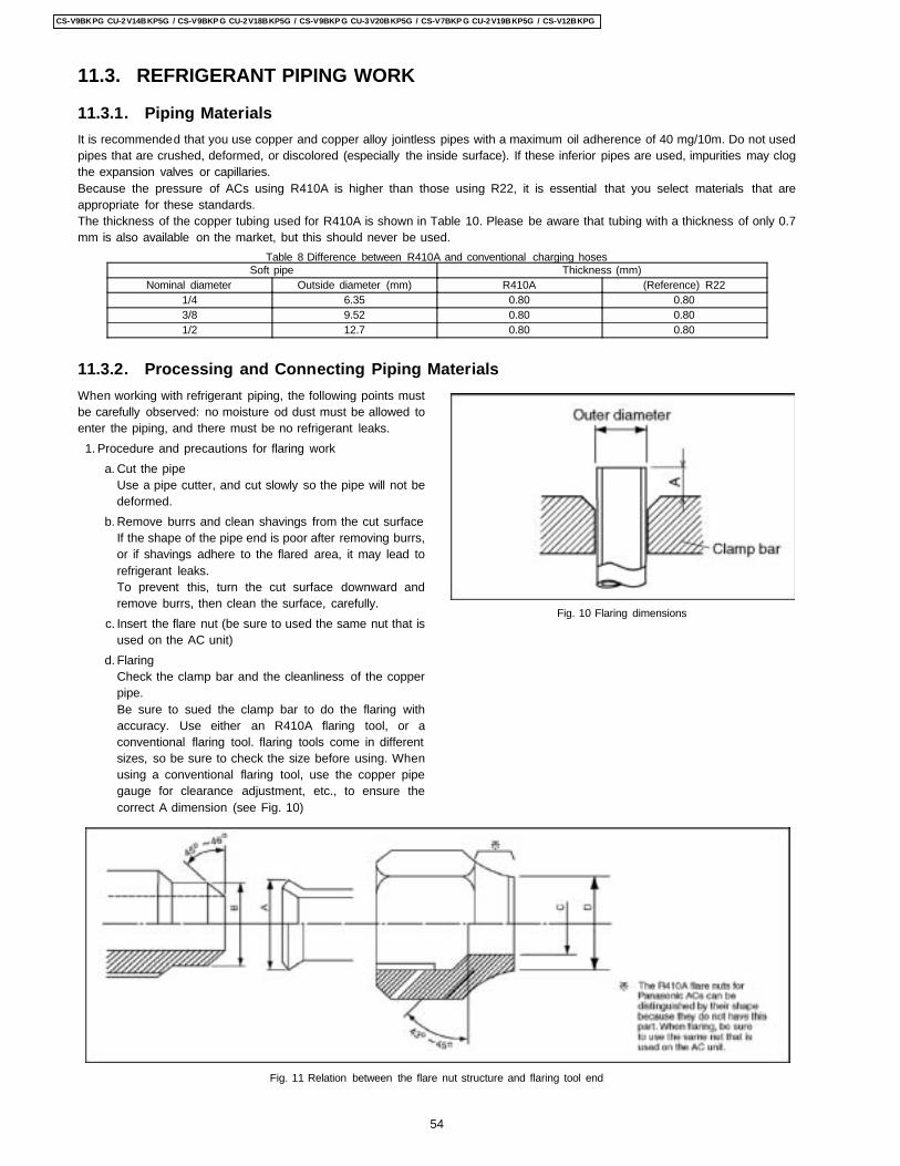
11.3. REFRIGERANT PIPING WORK
When working with refrigerant piping, the following points mustbe carefully observed: no moisture od dust must be allowed toenter the piping, and there must be no refrigerant leaks. 1. Procedure and precautions for flaring work
a. Cut the pipeUse a pipe cutter, and cut slowly so the pipe will not bedeformed.
b. Remove burrs and clean shavings from the cut surfaceIf the shape of the pipe end is poor after removing burrs,or if shavings adhere to the flared area, it may lead torefrigerant leaks.To prevent this, turn the cut surface downward andremove burrs, then clean the surface, carefully.
c. Insert the flare nut (be sure to used the same nut that isused on the AC unit)
d. FlaringCheck the clamp bar and the cleanliness of the copperpipe.Be sure to sued the clamp bar to do the flaring withaccuracy. Use either an R410A flaring tool, or aconventional flaring tool. flaring tools come in differentsizes, so be sure to check the size before using. Whenusing a conventional flaring tool, use the copper pipegauge for clearance adjustment, etc., to ensure thecorrect A dimension (see Fig. 10)
Fig. 10 Flaring dimensions
11.3.1. Piping MaterialsIt is recommended that you use copper and copper alloy jointless pipes with a maximum oil adherence of 40 mg/10m. Do not usedpipes that are crushed, deformed, or discolored (especially the inside surface). If these inferior pipes are used, impurities may clogthe expansion valves or capillaries.Because the pressure of ACs using R410A is higher than those using R22, it is essential that you select materials that areappropriate for these standards.The thickness of the copper tubing used for R410A is shown in Table 10. Please be aware that tubing with a thickness of only 0.7mm is also available on the market, but this should never be used.
Table 8 Difference between R410A and conventional charging hosesSoft pipe Thickness (mm)
Nominal diameter Outside diameter (mm) R410A (Reference) R221/4 6.35 0.80 0.803/8 9.52 0.80 0.801/2 12.7 0.80 0.80
11.3.2. Processing and Connecting Piping Materials
Fig. 11 Relation between the flare nut structure and flaring tool end
54
CS-V9BKPG CU-2V14BKP5G / CS-V9BKP G CU-2V18BKP5G / CS-V9BKP G CU-3V20BKP5G / CS-V7BKP G CU-2V19BKP5G / CS-V12BKPG
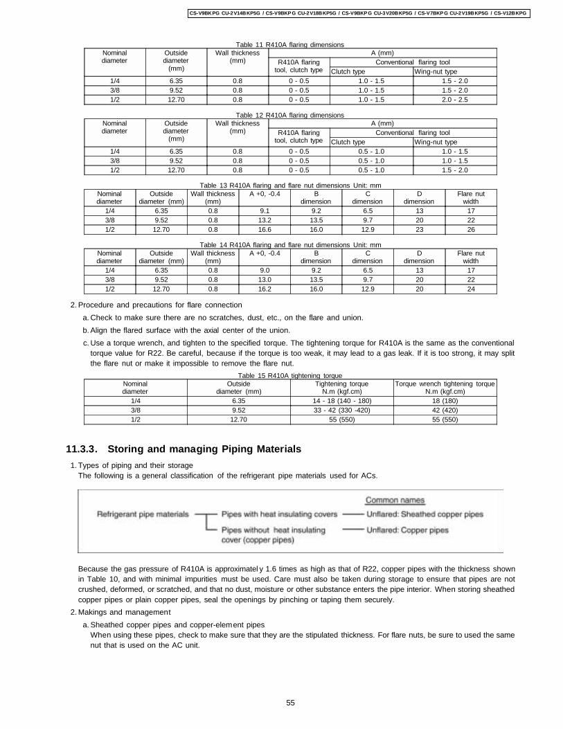
2. Procedure and precautions for flare connection
Table 11 R410A flaring dimensionsNominaldiameter
Outsidediameter
(mm)
Wall thickness(mm)
A (mm)R410A flaring
tool, clutch typeConventional flaring tool
Clutch type Wing-nut type1/4 6.35 0.8 0 - 0.5 1.0 - 1.5 1.5 - 2.03/8 9.52 0.8 0 - 0.5 1.0 - 1.5 1.5 - 2.01/2 12.70 0.8 0 - 0.5 1.0 - 1.5 2.0 - 2.5
Table 12 R410A flaring dimensionsNominaldiameter
Outsidediameter
(mm)
Wall thickness(mm)
A (mm)R410A flaring
tool, clutch typeConventional flaring tool
Clutch type Wing-nut type1/4 6.35 0.8 0 - 0.5 0.5 - 1.0 1.0 - 1.53/8 9.52 0.8 0 - 0.5 0.5 - 1.0 1.0 - 1.51/2 12.70 0.8 0 - 0.5 0.5 - 1.0 1.5 - 2.0
Table 13 R410A flaring and flare nut dimensions Unit: mmNominaldiameter
Outsidediameter (mm)
Wall thickness(mm)
A +0, -0.4 Bdimension
Cdimension
Ddimension
Flare nutwidth
1/4 6.35 0.8 9.1 9.2 6.5 13 173/8 9.52 0.8 13.2 13.5 9.7 20 221/2 12.70 0.8 16.6 16.0 12.9 23 26
Table 14 R410A flaring and flare nut dimensions Unit: mmNominaldiameter
Outsidediameter (mm)
Wall thickness(mm)
A +0, -0.4 Bdimension
Cdimension
Ddimension
Flare nutwidth
1/4 6.35 0.8 9.0 9.2 6.5 13 173/8 9.52 0.8 13.0 13.5 9.7 20 221/2 12.70 0.8 16.2 16.0 12.9 20 24
a. Check to make sure there are no scratches, dust, etc., on the flare and union. b. Align the flared surface with the axial center of the union. c. Use a torque wrench, and tighten to the specified torque. The tightening torque for R410A is the same as the conventional
torque value for R22. Be careful, because if the torque is too weak, it may lead to a gas leak. If it is too strong, it may splitthe flare nut or make it impossible to remove the flare nut.
Table 15 R410A tightening torqueNominaldiameter
Outsidediameter (mm)
Tightening torqueN.m (kgf.cm)
Torque wrench tightening torqueN.m (kgf.cm)
1/4 6.35 14 - 18 (140 - 180) 18 (180)3/8 9.52 33 - 42 (330 -420) 42 (420)1/2 12.70 55 (550) 55 (550)
11.3.3. Storing and managing Piping Materials 1. Types of piping and their storage
The following is a general classification of the refrigerant pipe materials used for ACs.
Because the gas pressure of R410A is approximatel y 1.6 times as high as that of R22, copper pipes with the thickness shownin Table 10, and with minimal impurities must be used. Care must also be taken during storage to ensure that pipes are notcrushed, deformed, or scratched, and that no dust, moisture or other substance enters the pipe interior. When storing sheathedcopper pipes or plain copper pipes, seal the openings by pinching or taping them securely.
2. Makings and management a. Sheathed copper pipes and copper-element pipes
When using these pipes, check to make sure that they are the stipulated thickness. For flare nuts, be sure to used the samenut that is used on the AC unit.
55
CS-V9BKPG CU-2V14BKP5G / CS-V9BKP G CU-2V18BKP5G / CS-V9BKP G CU-3V20BKP5G / CS-V7BKP G CU-2V19BKP5G / CS-V12BKPG
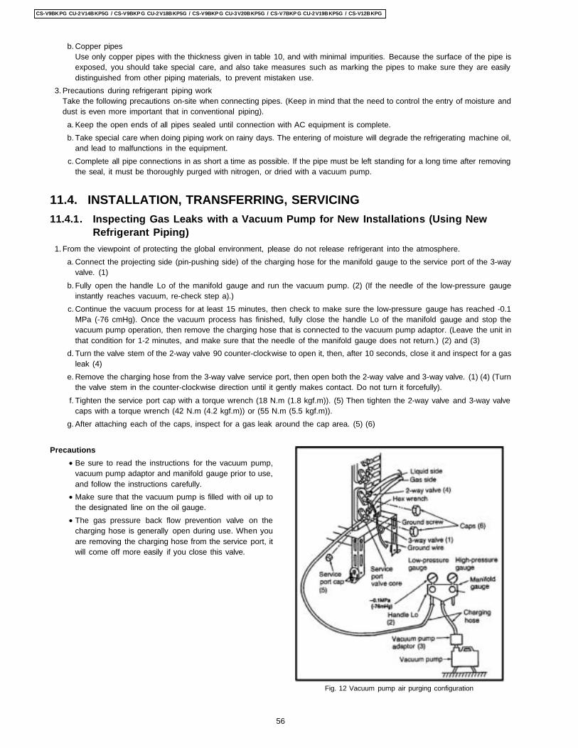
Precautions • Be sure to read the instructions for the vacuum pump,
vacuum pump adaptor and manifold gauge prior to use,and follow the instructions carefully.
• Make sure that the vacuum pump is filled with oil up tothe designated line on the oil gauge.
• The gas pressure back flow prevention valve on thecharging hose is generally open during use. When youare removing the charging hose from the service port, itwill come off more easily if you close this valve.
Fig. 12 Vacuum pump air purging configuration
b. Copper pipesUse only copper pipes with the thickness given in table 10, and with minimal impurities. Because the surface of the pipe isexposed, you should take special care, and also take measures such as marking the pipes to make sure they are easilydistinguished from other piping materials, to prevent mistaken use.
3. Precautions during refrigerant piping workTake the following precautions on-site when connecting pipes. (Keep in mind that the need to control the entry of moisture anddust is even more important that in conventional piping). a. Keep the open ends of all pipes sealed until connection with AC equipment is complete. b. Take special care when doing piping work on rainy days. The entering of moisture will degrade the refrigerating machine oil,
and lead to malfunctions in the equipment. c. Complete all pipe connections in as short a time as possible. If the pipe must be left standing for a long time after removing
the seal, it must be thoroughly purged with nitrogen, or dried with a vacuum pump.
11.4. INSTALLATION, TRANSFERRING, SERVICING11.4.1. Inspecting Gas Leaks with a Vacuum Pump for New Installations (Using New
Refrigerant Piping) 1. From the viewpoint of protecting the global environment, please do not release refrigerant into the atmosphere.
a. Connect the projecting side (pin-pushing side) of the charging hose for the manifold gauge to the service port of the 3-wayvalve. (1)
b. Fully open the handle Lo of the manifold gauge and run the vacuum pump. (2) (If the needle of the low-pressure gaugeinstantly reaches vacuum, re-check step a).)
c. Continue the vacuum process for at least 15 minutes, then check to make sure the low-pressure gauge has reached -0.1MPa (-76 cmHg). Once the vacuum process has finished, fully close the handle Lo of the manifold gauge and stop thevacuum pump operation, then remove the charging hose that is connected to the vacuum pump adaptor. (Leave the unit inthat condition for 1-2 minutes, and make sure that the needle of the manifold gauge does not return.) (2) and (3)
d. Turn the valve stem of the 2-way valve 90 counter-clockwise to open it, then, after 10 seconds, close it and inspect for a gasleak (4)
e. Remove the charging hose from the 3-way valve service port, then open both the 2-way valve and 3-way valve. (1) (4) (Turnthe valve stem in the counter-clockwise direction until it gently makes contact. Do not turn it forcefully).
f. Tighten the service port cap with a torque wrench (18 N.m (1.8 kgf.m)). (5) Then tighten the 2-way valve and 3-way valvecaps with a torque wrench (42 N.m (4.2 kgf.m)) or (55 N.m (5.5 kgf.m)).
g. After attaching each of the caps, inspect for a gas leak around the cap area. (5) (6)
56
CS-V9BKPG CU-2V14BKP5G / CS-V9BKP G CU-2V18BKP5G / CS-V9BKP G CU-3V20BKP5G / CS-V7BKP G CU-2V19BKP5G / CS-V12BKPG
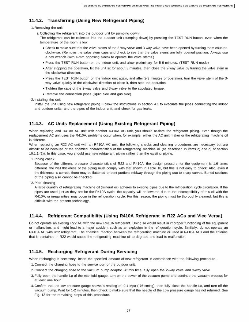
11.4.2. Transferring (Using New Refrigerant Piping) 1. Removing the unit
a. Collecting the refrigerant into the outdoor unit by pumping downThe refrigerant can be collected into the outdoor unit (pumping down) by pressing the TEST RUN button, even when thetemperature of the room is low. • Check to make sure that the valve stems of the 2-way valve and 3-way valve have been opened by turning them counter-
clockwise. (Remove the valve stem caps and check to see that the valve stems are fully opened position. Always usea hex wrench (with 4-mm opposing sides) to operate the valve stems.)
• Press the TEST RUN button on the indoor unit, and allow preliminary for 5-6 minutes. (TEST RUN mode) • After stopping the operation, let the unit sit for about 3 minutes, then close the 2-way valve by turning the valve stem in
the clockwise direction. • Press the TEST RUN button on the indoor unit again, and after 2-3 minutes of operation, turn the valve stem of the 3-
way valve quickly in the clockwise direction to close it, then stop the operation. • Tighten the caps of the 2-way valve and 3-way valve to the stipulated torque. • Remove the connection pipes (liquid side and gas side).
2. Installing the unitInstall the unit using new refrigerant piping. Follow the instructions in section 4.1 to evacuate the pipes connecting the indoorand outdoor units, and the pipes of the indoor unit, and check for gas leaks.
11.4.3. AC Units Replacement (Using Existing Refrigerant Piping)When replacing and R410A AC unit with another R410A AC unit, you should re-flare the refrigerant piping. Even though thereplacement AC unit uses the R410A, problems occur when, for example, either the AC unit maker or the refrigerating machine oilis different.When replacing an R22 AC unit with an R410A AC unit, the following checks and cleaning procedures are necessary but aredifficult to do because of the chemical characteristic s of the refrigerating machine oil (as described in items c) and d) of section10.1.1.(2)). In this case, you should use new refrigerant piping rather than the existing piping. 1. Piping check
Because of the different pressure characteristic s of R22 and R410A, the design pressure for the equipment is 1.6 timesdifferent. the wall thickness of the piping must comply with that shown in Table 10, but this is not easy to check. Also, even ifthe thickness is correct, there may be flattened or bent portions midway through the piping due to sharp curves. Buried sectionsof the piping also cannot be checked.
2. Pipe cleaningA large quantity of refrigerating machine oil (mineral oil) adheres to existing pipes due to the refrigeration cycle circulation. If thepipes are used just as they are for the R410A cycle, the capacity will be lowered due to the incompatibilit y of this oil with theR410A, or irregularities may occur in the refrigeration cycle. For this reason, the piping must be thoroughly cleaned, but this isdifficult with the present technology.
11.4.4. Refrigerant Compatibility (Using R410A Refrigerant in R22 ACs and Vice Versa)Do not operate an existing R22 AC with the new R410A refrigerant. Doing so would result in improper functioning of the equipmentor malfunction, and might lead to a major accident such as an explosion in the refrigeration cycle. Similarly, do not operate anR410A AC with R22 refrigerant. The chemical reaction between the refrigerating machine oil used in R410A ACs and the chlorinethat is contained in R22 would cause the refrigerating machine oil to degrade and lead to malfunction.
11.4.5. Recharging Refrigerant During ServicingWhen recharging is necessary, insert the specified amount of new refrigerant in accordance with the following procedure. 1. Connect the charging hose to the service port of the outdoor unit. 2. Connect the charging hose to the vacuum pump adaptor. At this time, fully open the 2-way valve and 3-way valve. 3. Fully open the handle Lo of the manifold gauge, turn on the power of the vacuum pump and continue the vacuum process for
at least one hour. 4. Confirm that the low pressure gauge shows a reading of -0.1 Mpa (-76 cmHg), then fully close the handle Lo, and turn off the
vacuum pump. Wait for 1-2 minutes, then check to make sure that the needle of the Low pressure gauge has not returned. SeeFig. 13 for the remaining steps of this procedure.
57
CS-V9BKPG CU-2V14BKP5G / CS-V9BKP G CU-2V18BKP5G / CS-V9BKP G CU-3V20BKP5G / CS-V7BKP G CU-2V19BKP5G / CS-V12BKPG
5. Set the refrigerant cylinder onto the electronic scale, then correct the hose the cylinder and to the connection port for theelectronic scale. (1)(2)Precaution:
Be sure to set up the cylinder for liquid charging. If you use a cylinder equipped with a siphon tube, you can charge the liquidwithout having to turn the cylinder around
6. Remove the charging hose of the manifold gauge from the vacuum pump adaptor, and connect it to the connection port of theelectronic scale. (2)(3)
7. Open the valve of the refrigerant cylinder, then open the charging valve slightly and close it. Next, press the check valve of themanifold gauge and purge the air. (2)(4) (Watch the liquid refrigerant closely at this point.)
8. After adjusting the electronic scale to zero, open the charging valve, then open the valve Lo of the manifold gauge and chargewith the liquid refrigerant. (2)(5) (Be sure to read the operating instructions for the electronic scale.)
9. If you cannot charge the stipulated amount, operate the unit in the cooling mode while charging a little of the liquid at a time(about 150 g/time as a guideline). If the charging amount is insufficient from one operation, wait about one minute, then use thesame procedure to do the liquid charging again.Precaution:
Never use the gas side to allow a larger amount of liquid refrigerant to be charged while operating the unit.10. Close the charging valve, and after charging the liquid refrigerant inside the charging hose, fully close the valve Lo of the
manifold gauge, and stop the operation of the unit. (2)(5)11. Quickly remove the charging hose from the service port. (6) If you stop midway through, the refrigerant that is in the cycle will
be discharged.12. After putting on the caps for the service port and operating valve, inspect around the caps for a gas leak. (6)(7)
Fig. 13 Re-charging refrigerant
11.4.6. BrazingAs brazing requires sophisticated techniques and experiences, it must be performed by a qualified person.In order to prevent the oxide film from occurring in the pipe interior during brazing, it is effective to proceed with brazing while lettingdry nitrogen gas (N2) flow.
58
CS-V9BKPG CU-2V14BKP5G / CS-V9BKP G CU-2V18BKP5G / CS-V9BKP G CU-3V20BKP5G / CS-V7BKP G CU-2V19BKP5G / CS-V12BKPG
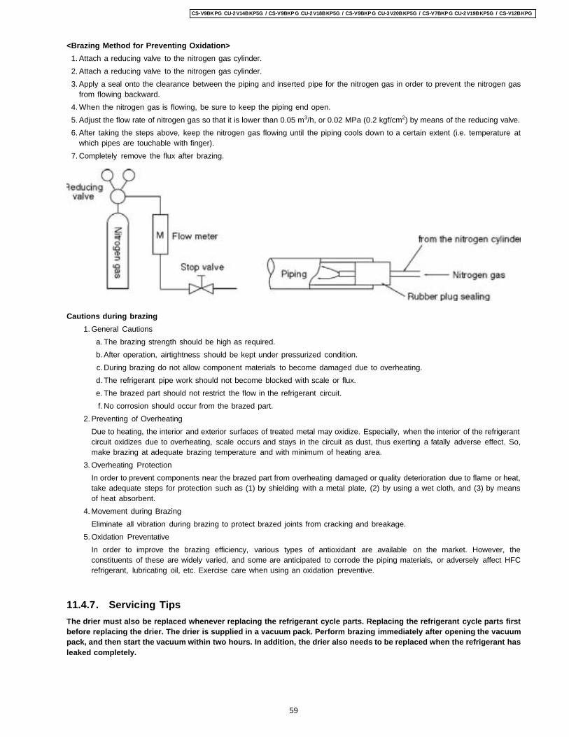
<Brazing Method for Preventing Oxidation> 1. Attach a reducing valve to the nitrogen gas cylinder. 2. Attach a reducing valve to the nitrogen gas cylinder. 3. Apply a seal onto the clearance between the piping and inserted pipe for the nitrogen gas in order to prevent the nitrogen gas
from flowing backward. 4. When the nitrogen gas is flowing, be sure to keep the piping end open. 5. Adjust the flow rate of nitrogen gas so that it is lower than 0.05 m3/h, or 0.02 MPa (0.2 kgf/cm2) by means of the reducing valve. 6. After taking the steps above, keep the nitrogen gas flowing until the piping cools down to a certain extent (i.e. temperature at
which pipes are touchable with finger). 7. Completely remove the flux after brazing.
Cautions during brazing 1. General Cautions
a. The brazing strength should be high as required. b. After operation, airtightness should be kept under pressurized condition. c. During brazing do not allow component materials to become damaged due to overheating. d. The refrigerant pipe work should not become blocked with scale or flux. e. The brazed part should not restrict the flow in the refrigerant circuit. f. No corrosion should occur from the brazed part.
2. Preventing of OverheatingDue to heating, the interior and exterior surfaces of treated metal may oxidize. Especially, when the interior of the refrigerantcircuit oxidizes due to overheating, scale occurs and stays in the circuit as dust, thus exerting a fatally adverse effect. So,make brazing at adequate brazing temperature and with minimum of heating area.
3. Overheating ProtectionIn order to prevent components near the brazed part from overheating damaged or quality deterioration due to flame or heat,take adequate steps for protection such as (1) by shielding with a metal plate, (2) by using a wet cloth, and (3) by meansof heat absorbent.
4. Movement during BrazingEliminate all vibration during brazing to protect brazed joints from cracking and breakage.
5. Oxidation PreventativeIn order to improve the brazing efficiency, various types of antioxidant are available on the market. However, theconstituents of these are widely varied, and some are anticipated to corrode the piping materials, or adversely affect HFCrefrigerant, lubricating oil, etc. Exercise care when using an oxidation preventive.
11.4.7. Servicing TipsThe drier must also be replaced whenever replacing the refrigerant cycle parts. Replacing the refrigerant cycle parts firstbefore replacing the drier. The drier is supplied in a vacuum pack. Perform brazing immediately after opening the vacuumpack, and then start the vacuum within two hours. In addition, the drier also needs to be replaced when the refrigerant hasleaked completely.
59
CS-V9BKPG CU-2V14BKP5G / CS-V9BKP G CU-2V18BKP5G / CS-V9BKP G CU-3V20BKP5G / CS-V7BKP G CU-2V19BKP5G / CS-V12BKPG

1. The Electronic Controller, a Signal Receiver and anIndicator (Fig. 3) can be seen by the below steps:
• Remove the 2 caps and 2 screws at the bottom of theFront Grille. (Fig. 1)
• Remove the Front Grille by releasing the 2 hooks at thetop of the Front Grille. (Fig. 1)
• Remove the Control Board Cover by releasing the 2tabs at left, 1 tab on top and 1 tab at right side of theControl Board Cover. (Fig. 2)
2. To remove the Electronic Controller: • Release the Particular Piece. (Fig. 3) • Release the hook that hold the Electronic Controller.
(Fig. 3)
• Remove the Control Board by:-
− Releasing CN-REC/DISP connectors. (Fig. 4) − Releasing CN-FM connectors. (Fig. 4) − Releasing CN-STM connector. (Fig. 4) − Removing the Earth Wire screw. (Fig. 4) − Releasing the Intake Air Sensor. (Fig. 4) − Releasing the Piping Sensor. (Fig. 4)
Fig. 1
Fig. 2
Fig. 3
Fig. 4
12 Servicing InformationCaution:
• Pb free solder has a higher melting point than standard solder; Typically the melting point is 50 - 70°F (30 - 40°C) higher. Please usea high temperature soldering iron. In case of the soldering iron with temperature control, please set it to 700 ± 20°F (370 ± 10°C).
• Pb free solder will tend to splash when heated too high (about 1100° F/600°C).
12.1. Indoor Electronic Controllers Removal Procedures
12.2. Indoor Fan Motor and Cross Flow Fan Removal Procedures
60
CS-V9BKPG CU-2V14BKP5G / CS-V9BKP G CU-2V18BKP5G / CS-V9BKP G CU-3V20BKP5G / CS-V7BKP G CU-2V19BKP5G / CS-V12BKPG
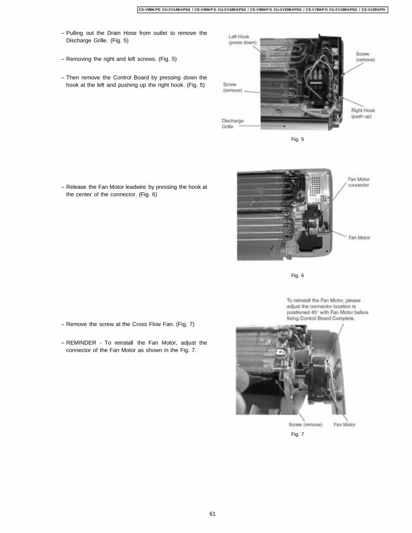
− Pulling out the Drain Hose from outlet to remove theDischarge Grille. (Fig. 5)
− Removing the right and left screws. (Fig. 5)
− Then remove the Control Board by pressing down thehook at the left and pushing up the right hook. (Fig. 5)
− Release the Fan Motor leadwire by pressing the hook atthe center of the connector. (Fig. 6)
− Remove the screw at the Cross Flow Fan. (Fig. 7)
− REMINDER - To reinstall the Fan Motor, adjust theconnector of the Fan Motor as shown in the Fig. 7.
Fig. 5
Fig. 6
Fig. 7
61
CS-V9BKPG CU-2V14BKP5G / CS-V9BKP G CU-2V18BKP5G / CS-V9BKP G CU-3V20BKP5G / CS-V7BKP G CU-2V19BKP5G / CS-V12BKPG
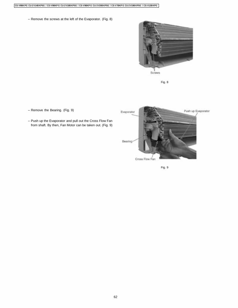
− Remove the screws at the left of the Evaporator. (Fig. 8)
− Remove the Bearing. (Fig. 9)
− Push up the Evaporator and pull out the Cross Flow Fanfrom shaft. By then, Fan Motor can be taken out. (Fig. 9)
Fig. 8
Fig. 9
62
CS-V9BKPG CU-2V14BKP5G / CS-V9BKP G CU-2V18BKP5G / CS-V9BKP G CU-3V20BKP5G / CS-V7BKP G CU-2V19BKP5G / CS-V12BKPG
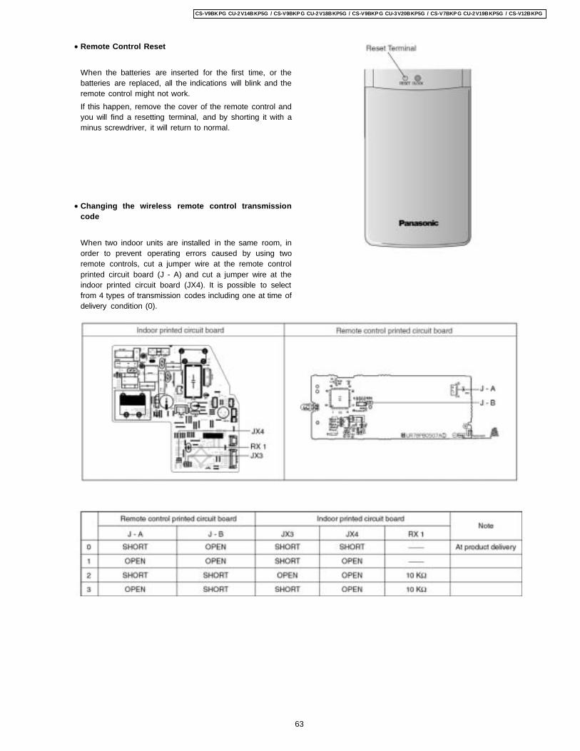
• Remote Control Reset
When the batteries are inserted for the first time, or thebatteries are replaced, all the indications will blink and theremote control might not work.If this happen, remove the cover of the remote control andyou will find a resetting terminal, and by shorting it with aminus screwdriver, it will return to normal.
• Changing the wireless remote control transmissioncode
When two indoor units are installed in the same room, inorder to prevent operating errors caused by using tworemote controls, cut a jumper wire at the remote controlprinted circuit board (J - A) and cut a jumper wire at theindoor printed circuit board (JX4). It is possible to selectfrom 4 types of transmission codes including one at time ofdelivery condition (0).
63
CS-V9BKPG CU-2V14BKP5G / CS-V9BKP G CU-2V18BKP5G / CS-V9BKP G CU-3V20BKP5G / CS-V7BKP G CU-2V19BKP5G / CS-V12BKPG
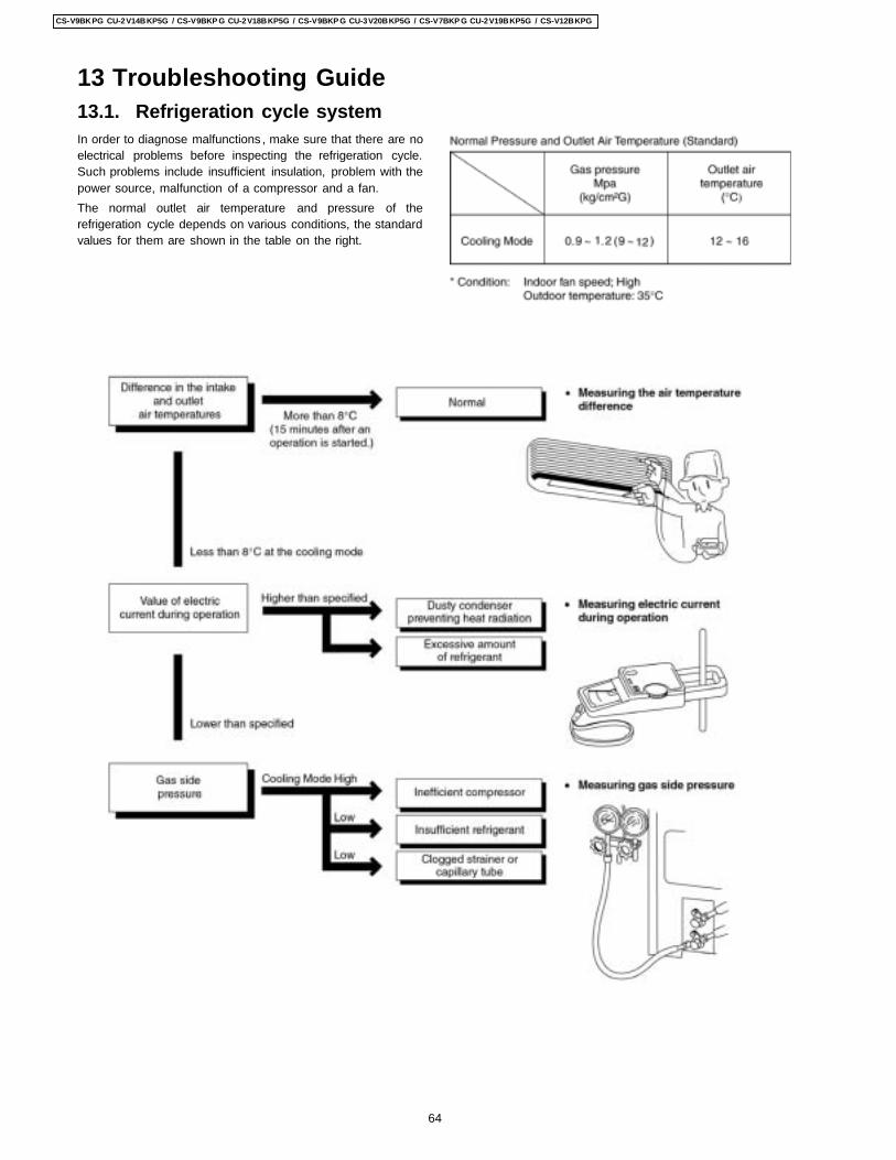
13.1. Refrigeration cycle systemIn order to diagnose malfunctions , make sure that there are noelectrical problems before inspecting the refrigeration cycle.Such problems include insufficient insulation, problem with thepower source, malfunction of a compressor and a fan.The normal outlet air temperature and pressure of therefrigeration cycle depends on various conditions, the standardvalues for them are shown in the table on the right.
13 Troubleshooting Guide
64
CS-V9BKPG CU-2V14BKP5G / CS-V9BKP G CU-2V18BKP5G / CS-V9BKP G CU-3V20BKP5G / CS-V7BKP G CU-2V19BKP5G / CS-V12BKPG
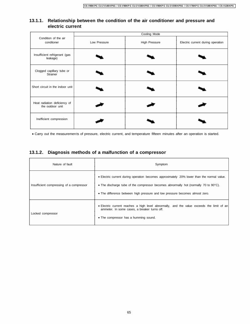
13.1.1. Relationship between the condition of the air conditioner and pressure andelectric current
Cooling ModeCondition of the air
conditoner Low Pressure High Pressure Electric current during operation
Insufficient refrigerant (gasleakage)
Clogged capillary tube orStrainer
Short circuit in the indoor unit
Heat radiation deficiency ofthe outdoor unit
Inefficient compression
• Carry out the measuremen ts of pressure, electric current, and temperature fifteen minutes after an operation is started.
13.1.2. Diagnosis methods of a malfunction of a compressor
Nature of fault Symptom
• Electric current during operation becomes approximately 20% lower than the normal value.
Insufficient compressing of a compressor • The discharge tube of the compressor becomes abnormally hot (normally 70 to 90°C).
• The difference between high pressure and low pressure becomes almost zero.
• Electric current reaches a high level abnormally, and the value exceeds the limit of anammeter. In some cases, a breaker turns off.
Locked compressor • The compressor has a humming sound.
65
CS-V9BKPG CU-2V14BKP5G / CS-V9BKP G CU-2V18BKP5G / CS-V9BKP G CU-3V20BKP5G / CS-V7BKP G CU-2V19BKP5G / CS-V12BKPG
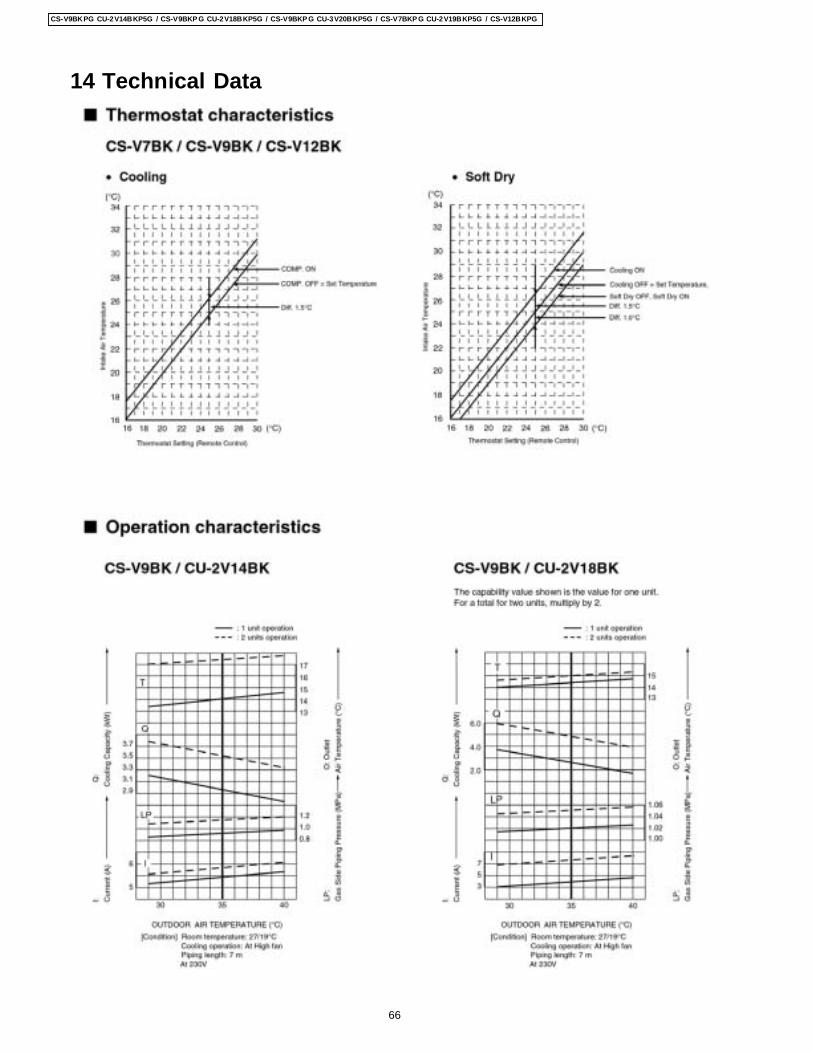
14 Technical Data
66
CS-V9BKPG CU-2V14BKP5G / CS-V9BKP G CU-2V18BKP5G / CS-V9BKP G CU-3V20BKP5G / CS-V7BKP G CU-2V19BKP5G / CS-V12BKPG
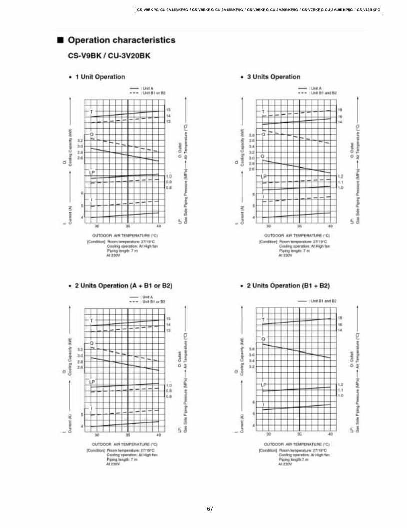
67
CS-V9BKPG CU-2V14BKP5G / CS-V9BKP G CU-2V18BKP5G / CS-V9BKP G CU-3V20BKP5G / CS-V7BKP G CU-2V19BKP5G / CS-V12BKPG
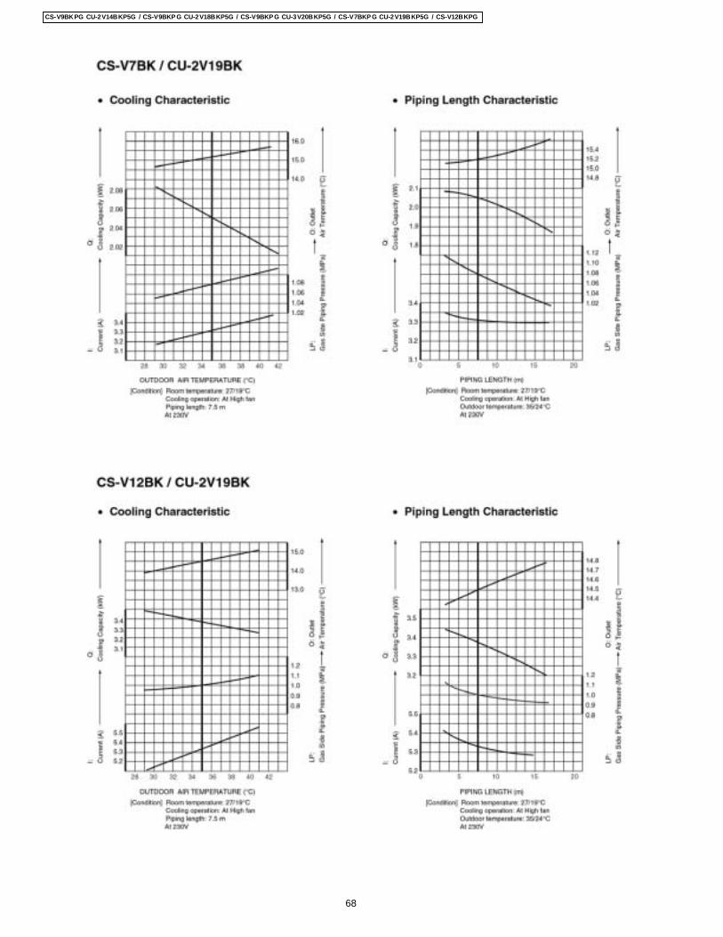
68
CS-V9BKPG CU-2V14BKP5G / CS-V9BKP G CU-2V18BKP5G / CS-V9BKP G CU-3V20BKP5G / CS-V7BKP G CU-2V19BKP5G / CS-V12BKPG
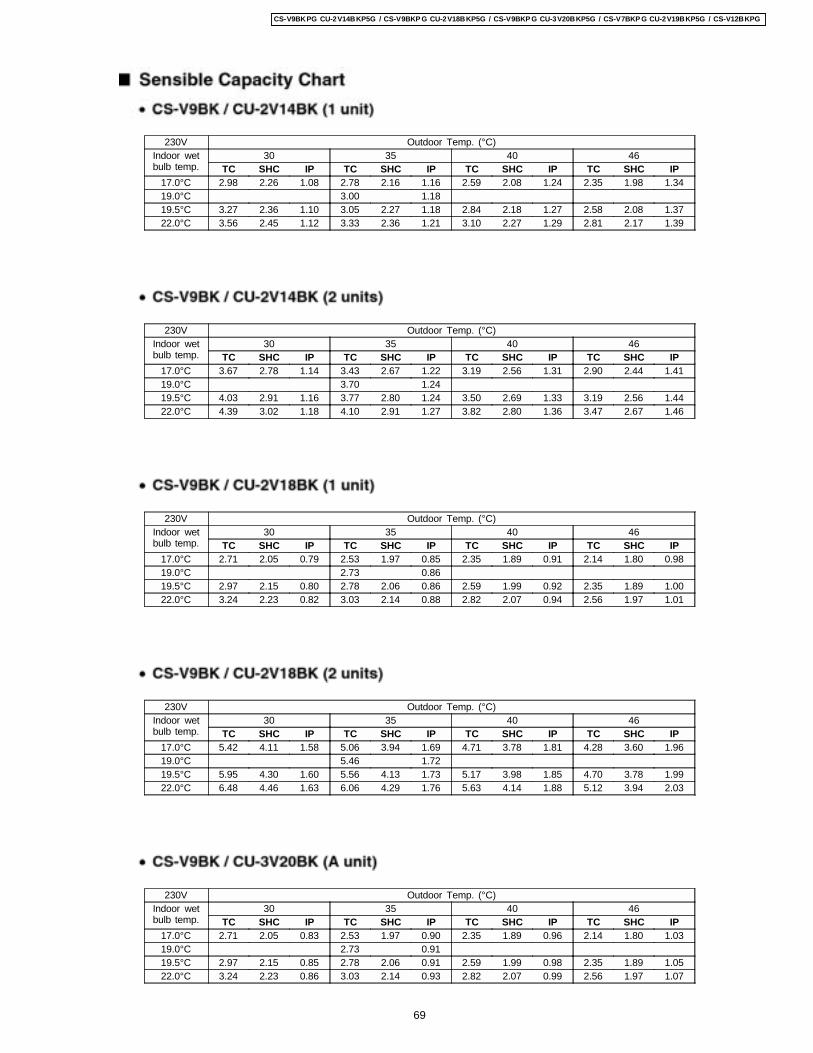
230V Outdoor Temp. (°C)Indoor wetbulb temp.
30 35 40 46TC SHC IP TC SHC IP TC SHC IP TC SHC IP
17.0°C 2.98 2.26 1.08 2.78 2.16 1.16 2.59 2.08 1.24 2.35 1.98 1.3419.0°C 3.00 1.1819.5°C 3.27 2.36 1.10 3.05 2.27 1.18 2.84 2.18 1.27 2.58 2.08 1.3722.0°C 3.56 2.45 1.12 3.33 2.36 1.21 3.10 2.27 1.29 2.81 2.17 1.39
230V Outdoor Temp. (°C)Indoor wetbulb temp.
30 35 40 46TC SHC IP TC SHC IP TC SHC IP TC SHC IP
17.0°C 3.67 2.78 1.14 3.43 2.67 1.22 3.19 2.56 1.31 2.90 2.44 1.4119.0°C 3.70 1.2419.5°C 4.03 2.91 1.16 3.77 2.80 1.24 3.50 2.69 1.33 3.19 2.56 1.4422.0°C 4.39 3.02 1.18 4.10 2.91 1.27 3.82 2.80 1.36 3.47 2.67 1.46
230V Outdoor Temp. (°C)Indoor wetbulb temp.
30 35 40 46TC SHC IP TC SHC IP TC SHC IP TC SHC IP
17.0°C 2.71 2.05 0.79 2.53 1.97 0.85 2.35 1.89 0.91 2.14 1.80 0.9819.0°C 2.73 0.8619.5°C 2.97 2.15 0.80 2.78 2.06 0.86 2.59 1.99 0.92 2.35 1.89 1.0022.0°C 3.24 2.23 0.82 3.03 2.14 0.88 2.82 2.07 0.94 2.56 1.97 1.01
230V Outdoor Temp. (°C)Indoor wetbulb temp.
30 35 40 46TC SHC IP TC SHC IP TC SHC IP TC SHC IP
17.0°C 5.42 4.11 1.58 5.06 3.94 1.69 4.71 3.78 1.81 4.28 3.60 1.9619.0°C 5.46 1.7219.5°C 5.95 4.30 1.60 5.56 4.13 1.73 5.17 3.98 1.85 4.70 3.78 1.9922.0°C 6.48 4.46 1.63 6.06 4.29 1.76 5.63 4.14 1.88 5.12 3.94 2.03
230V Outdoor Temp. (°C)Indoor wetbulb temp.
30 35 40 46TC SHC IP TC SHC IP TC SHC IP TC SHC IP
17.0°C 2.71 2.05 0.83 2.53 1.97 0.90 2.35 1.89 0.96 2.14 1.80 1.0319.0°C 2.73 0.9119.5°C 2.97 2.15 0.85 2.78 2.06 0.91 2.59 1.99 0.98 2.35 1.89 1.0522.0°C 3.24 2.23 0.86 3.03 2.14 0.93 2.82 2.07 0.99 2.56 1.97 1.07
69
CS-V9BKPG CU-2V14BKP5G / CS-V9BKP G CU-2V18BKP5G / CS-V9BKP G CU-3V20BKP5G / CS-V7BKP G CU-2V19BKP5G / CS-V12BKPG
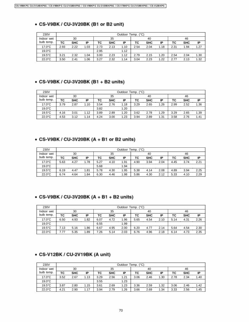
230V Outdoor Temp. (°C)Indoor wetbulb temp.
30 35 40 46TC SHC IP TC SHC IP TC SHC IP TC SHC IP
17.0°C 2.93 2.22 1.03 2.73 2.13 1.10 2.54 2.04 1.18 2.31 1.94 1.2719.0°C 2.95 1.1219.5°C 3.21 2.32 1.04 3.00 2.23 1.12 2.79 2.15 1.20 2.54 2.04 1.3022.0°C 3.50 2.41 1.06 3.27 2.32 1.14 3.04 2.23 1.22 2.77 2.13 1.32
230V Outdoor Temp. (°C)Indoor wetbulb temp.
30 35 40 46TC SHC IP TC SHC IP TC SHC IP TC SHC IP
17.0°C 3.79 2.87 1.10 3.54 2.76 1.18 3.29 2.65 1.26 2.99 2.52 1.3619.0°C 3.82 1.2019.5°C 4.16 3.01 1.12 3.89 2.89 1.20 3.62 2.78 1.29 3.29 2.65 1.3922.0°C 4.53 3.12 1.14 4.24 3.00 1.23 3.94 2.89 1.31 3.58 2.76 1.41
230V Outdoor Temp. (°C)Indoor wetbulb temp.
30 35 40 46TC SHC IP TC SHC IP TC SHC IP TC SHC IP
17.0°C 5.63 4.27 1.78 5.27 4.10 1.91 4.90 3.94 2.04 4.45 3.74 2.2119.0°C 5.68 1.9419.5°C 6.19 4.47 1.81 5.78 4.30 1.95 5.38 4.14 2.08 4.89 3.94 2.2522.0°C 6.74 4.64 1.84 6.30 4.46 1.98 5.86 4.30 2.12 5.33 4.10 2.29
230V Outdoor Temp. (°C)Indoor wetbulb temp.
30 35 40 46TC SHC IP TC SHC IP TC SHC IP TC SHC IP
17.0°C 6.50 4.93 1.82 6.07 4.72 1.96 5.65 4.54 2.10 5.14 4.31 2.2619.0°C 6.55 1.9919.5°C 7.13 5.16 1.86 6.67 4.95 2.00 6.20 4.77 2.14 5.64 4.54 2.3022.0°C 7.77 5.35 1.89 7.26 5.14 2.03 6.76 4.96 2.18 6.14 4.73 2.35
230V Outdoor Temp. (°C)Indoor wetbulb temp.
30 35 40 46TC SHC IP TC SHC IP TC SHC IP TC SHC IP
17.0°C 3.52 2.67 1.13 3.29 2.56 1.21 3.06 2.46 1.30 2.78 2.34 1.4019.0°C 3.55 1.2319.5°C 3.87 2.80 1.15 3.61 2.69 1.23 3.36 2.59 1.32 3.06 2.46 1.4222.0°C 4.21 2.90 1.17 3.94 2.79 1.26 3.66 2.69 1.34 3.33 2.56 1.45
70
CS-V9BKPG CU-2V14BKP5G / CS-V9BKP G CU-2V18BKP5G / CS-V9BKP G CU-3V20BKP5G / CS-V7BKP G CU-2V19BKP5G / CS-V12BKPG
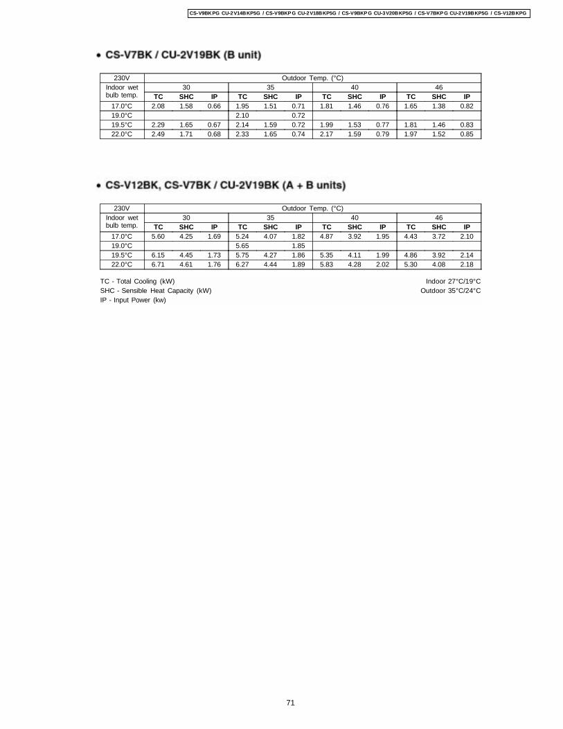
230V Outdoor Temp. (°C)Indoor wetbulb temp.
30 35 40 46TC SHC IP TC SHC IP TC SHC IP TC SHC IP
17.0°C 2.08 1.58 0.66 1.95 1.51 0.71 1.81 1.46 0.76 1.65 1.38 0.8219.0°C 2.10 0.7219.5°C 2.29 1.65 0.67 2.14 1.59 0.72 1.99 1.53 0.77 1.81 1.46 0.8322.0°C 2.49 1.71 0.68 2.33 1.65 0.74 2.17 1.59 0.79 1.97 1.52 0.85
230V Outdoor Temp. (°C)Indoor wetbulb temp.
30 35 40 46TC SHC IP TC SHC IP TC SHC IP TC SHC IP
17.0°C 5.60 4.25 1.69 5.24 4.07 1.82 4.87 3.92 1.95 4.43 3.72 2.1019.0°C 5.65 1.8519.5°C 6.15 4.45 1.73 5.75 4.27 1.86 5.35 4.11 1.99 4.86 3.92 2.1422.0°C 6.71 4.61 1.76 6.27 4.44 1.89 5.83 4.28 2.02 5.30 4.08 2.18
TC - Total Cooling (kW) Indoor 27°C/19°CSHC - Sensible Heat Capacity (kW) Outdoor 35°C/24°CIP - Input Power (kw)
71
CS-V9BKPG CU-2V14BKP5G / CS-V9BKP G CU-2V18BKP5G / CS-V9BKP G CU-3V20BKP5G / CS-V7BKP G CU-2V19BKP5G / CS-V12BKPG
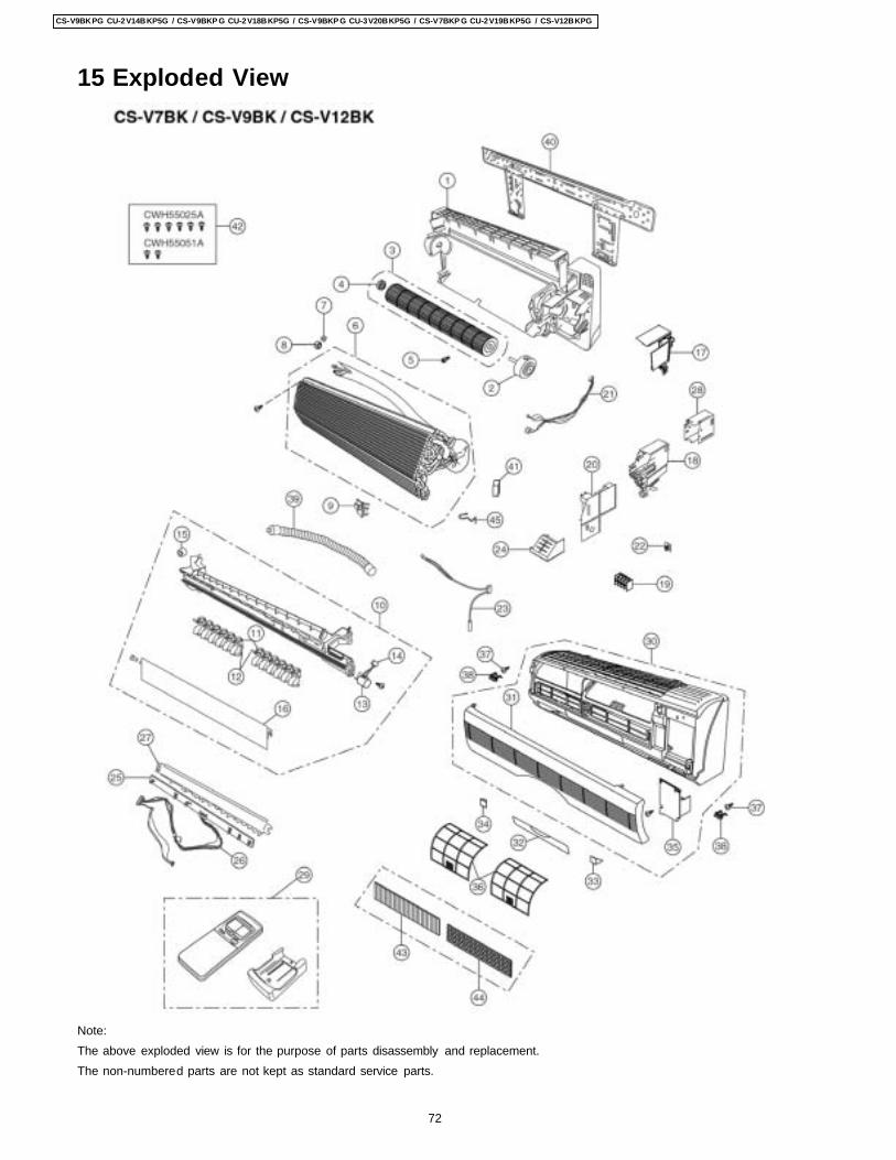
15 Exploded View
Note:The above exploded view is for the purpose of parts disassembly and replacement.The non-numbered parts are not kept as standard service parts.
72
CS-V9BKPG CU-2V14BKP5G / CS-V9BKP G CU-2V18BKP5G / CS-V9BKP G CU-3V20BKP5G / CS-V7BKP G CU-2V19BKP5G / CS-V12BKPG
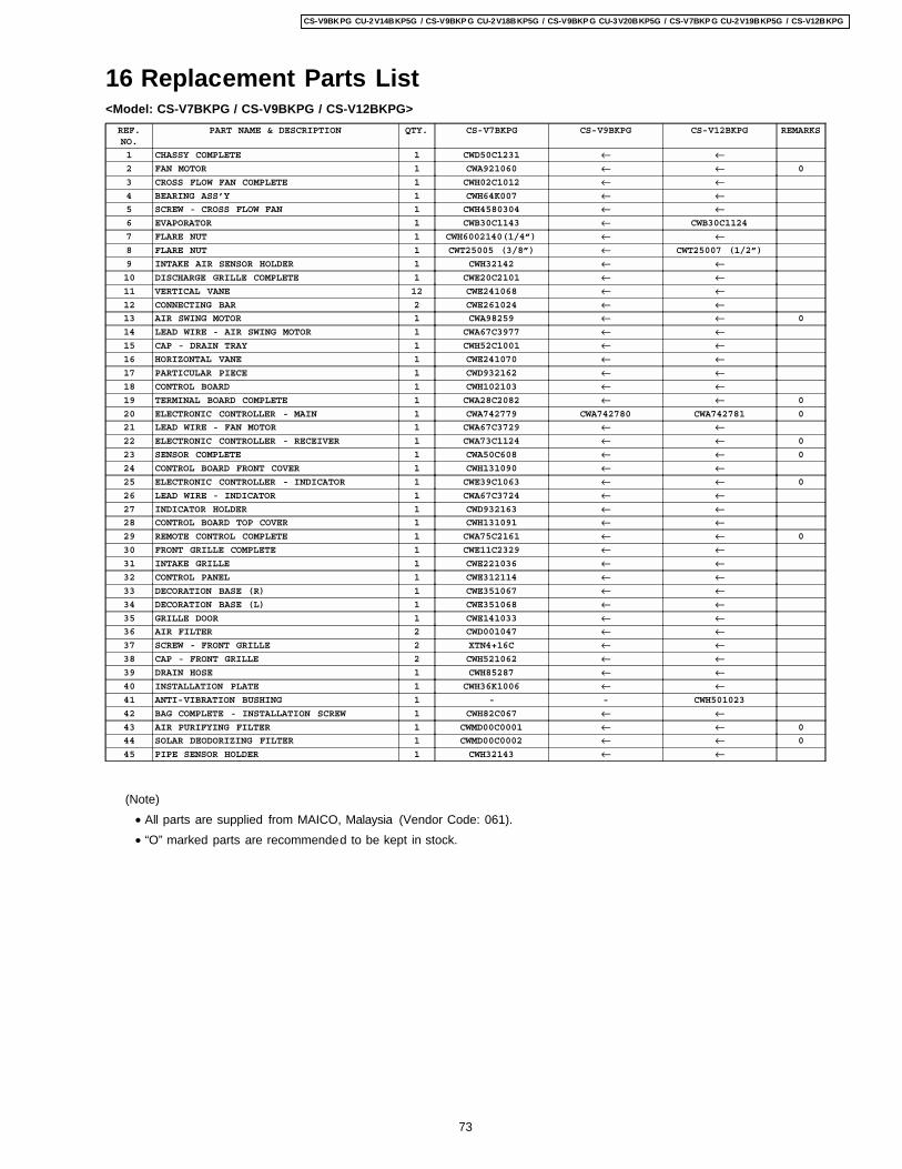
16 Replacement Parts List<Model: CS-V7BKPG / CS-V9BKPG / CS-V12BKPG>
REF.NO.
PART NAME & DESCRIPTION QTY. CS-V7BKPG CS-V9BKPG CS-V12BKPG REMARKS
1 CHASSY COMPLETE 1 CWD50C1231 ← ←2 FAN MOTOR 1 CWA921060 ← ← 0
3 CROSS FLOW FAN COMPLETE 1 CWH02C1012 ← ←4 BEARING ASS’Y 1 CWH64K007 ← ←5 SCREW - CROSS FLOW FAN 1 CWH4580304 ← ←6 EVAPORATOR 1 CWB30C1143 ← CWB30C1124
7 FLARE NUT 1 CWH6002140(1/4”) ← ←8 FLARE NUT 1 CWT25005 (3/8”) ← CWT25007 (1/2”)
9 INTAKE AIR SENSOR HOLDER 1 CWH32142 ← ←10 DISCHARGE GRILLE COMPLETE 1 CWE20C2101 ← ←11 VERTICAL VANE 12 CWE241068 ← ←12 CONNECTING BAR 2 CWE261024 ← ←13 AIR SWING MOTOR 1 CWA98259 ← ← 0
14 LEAD WIRE - AIR SWING MOTOR 1 CWA67C3977 ← ←15 CAP - DRAIN TRAY 1 CWH52C1001 ← ←16 HORIZONTAL VANE 1 CWE241070 ← ←17 PARTICULAR PIECE 1 CWD932162 ← ←18 CONTROL BOARD 1 CWH102103 ← ←19 TERMINAL BOARD COMPLETE 1 CWA28C2082 ← ← 0
20 ELECTRONIC CONTROLLER - MAIN 1 CWA742779 CWA742780 CWA742781 0
21 LEAD WIRE - FAN MOTOR 1 CWA67C3729 ← ←22 ELECTRONIC CONTROLLER - RECEIVER 1 CWA73C1124 ← ← 0
23 SENSOR COMPLETE 1 CWA50C608 ← ← 0
24 CONTROL BOARD FRONT COVER 1 CWH131090 ← ←25 ELECTRONIC CONTROLLER - INDICATOR 1 CWE39C1063 ← ← 0
26 LEAD WIRE - INDICATOR 1 CWA67C3724 ← ←27 INDICATOR HOLDER 1 CWD932163 ← ←28 CONTROL BOARD TOP COVER 1 CWH131091 ← ←29 REMOTE CONTROL COMPLETE 1 CWA75C2161 ← ← 0
30 FRONT GRILLE COMPLETE 1 CWE11C2329 ← ←31 INTAKE GRILLE 1 CWE221036 ← ←32 CONTROL PANEL 1 CWE312114 ← ←33 DECORATION BASE (R) 1 CWE351067 ← ←34 DECORATION BASE (L) 1 CWE351068 ← ←35 GRILLE DOOR 1 CWE141033 ← ←36 AIR FILTER 2 CWD001047 ← ←37 SCREW - FRONT GRILLE 2 XTN4+16C ← ←38 CAP - FRONT GRILLE 2 CWH521062 ← ←39 DRAIN HOSE 1 CWH85287 ← ←40 INSTALLATION PLATE 1 CWH36K1006 ← ←41 ANTI-VIBRATION BUSHING 1 - - CWH501023
42 BAG COMPLETE - INSTALLATION SCREW 1 CWH82C067 ← ←43 AIR PURIFYING FILTER 1 CWMD00C0001 ← ← 0
44 SOLAR DEODORIZING FILTER 1 CWMD00C0002 ← ← 0
45 PIPE SENSOR HOLDER 1 CWH32143 ← ←
(Note) • All parts are supplied from MAICO, Malaysia (Vendor Code: 061). • “O” marked parts are recommended to be kept in stock.
73
CS-V9BKPG CU-2V14BKP5G / CS-V9BKP G CU-2V18BKP5G / CS-V9BKP G CU-3V20BKP5G / CS-V7BKP G CU-2V19BKP5G / CS-V12BKPG
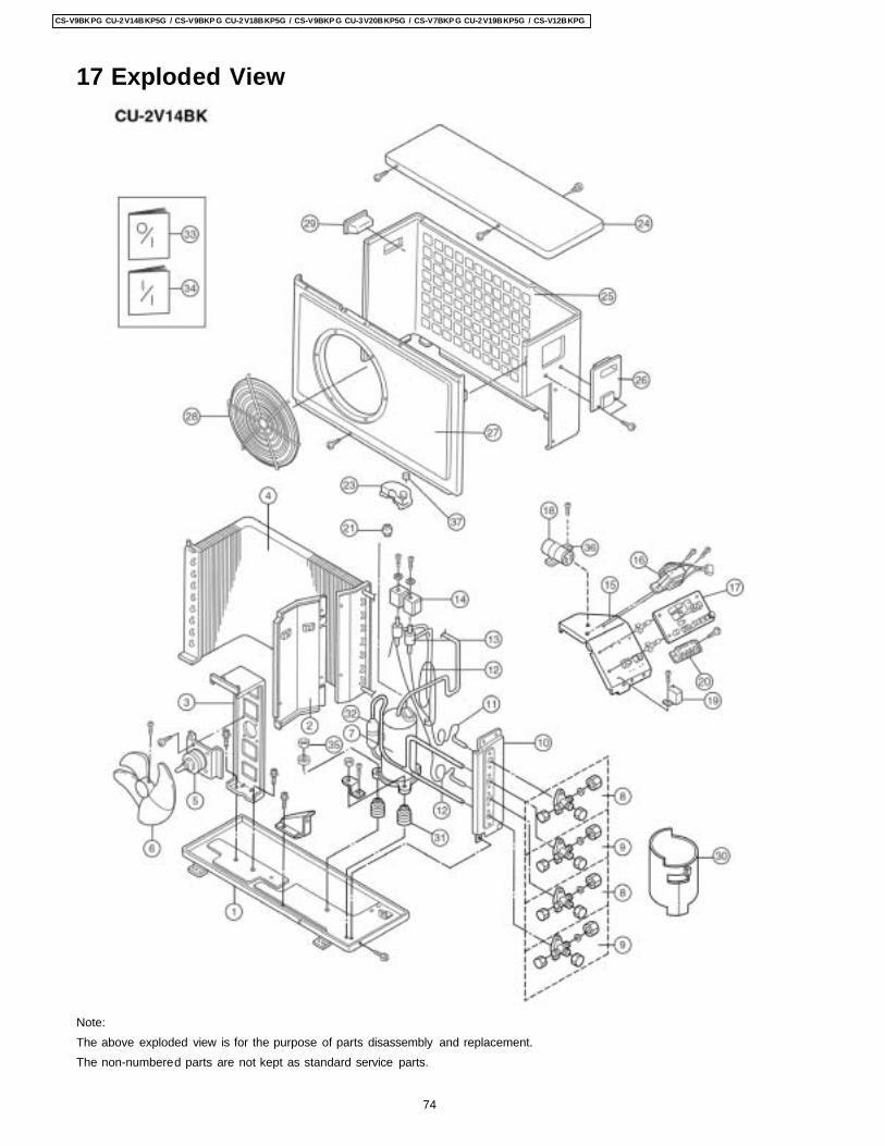
17 Exploded View
Note:The above exploded view is for the purpose of parts disassembly and replacement.The non-numbered parts are not kept as standard service parts.
74
CS-V9BKPG CU-2V14BKP5G / CS-V9BKP G CU-2V18BKP5G / CS-V9BKP G CU-3V20BKP5G / CS-V7BKP G CU-2V19BKP5G / CS-V12BKPG
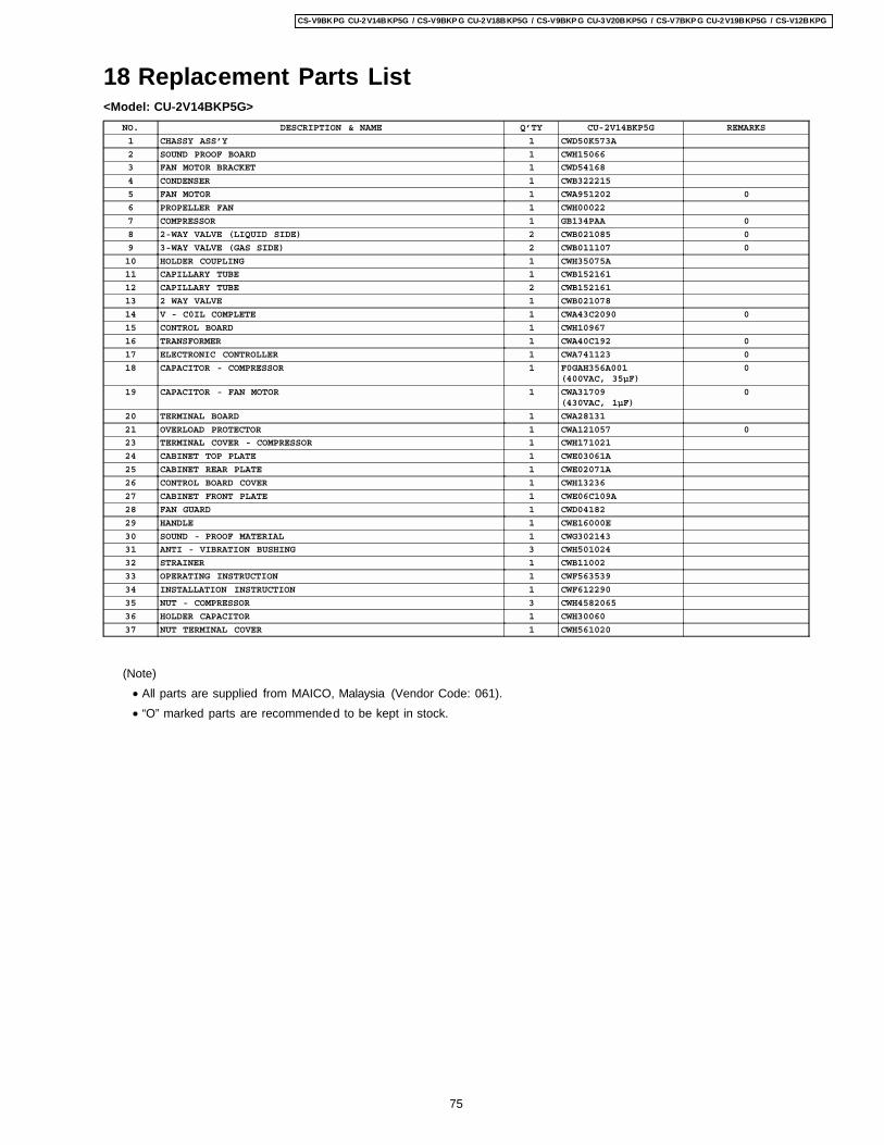
18 Replacement Parts List<Model: CU-2V14BKP5G>
NO. DESCRIPTION & NAME Q’TY CU-2V14BKP5G REMARKS
1 CHASSY ASS’Y 1 CWD50K573A
2 SOUND PROOF BOARD 1 CWH15066
3 FAN MOTOR BRACKET 1 CWD54168
4 CONDENSER 1 CWB322215
5 FAN MOTOR 1 CWA951202 0
6 PROPELLER FAN 1 CWH00022
7 COMPRESSOR 1 GB134PAA 0
8 2-WAY VALVE (LIQUID SIDE) 2 CWB021085 0
9 3-WAY VALVE (GAS SIDE) 2 CWB011107 0
10 HOLDER COUPLING 1 CWH35075A
11 CAPILLARY TUBE 1 CWB152161
12 CAPILLARY TUBE 2 CWB152161
13 2 WAY VALVE 1 CWB021078
14 V - C0IL COMPLETE 1 CWA43C2090 0
15 CONTROL BOARD 1 CWH10967
16 TRANSFORMER 1 CWA40C192 0
17 ELECTRONIC CONTROLLER 1 CWA741123 0
18 CAPACITOR - COMPRESSOR 1 F0GAH356A001(400VAC, 35µF)
0
19 CAPACITOR - FAN MOTOR 1 CWA31709(430VAC, 1µF)
0
20 TERMINAL BOARD 1 CWA28131
21 OVERLOAD PROTECTOR 1 CWA121057 0
23 TERMINAL COVER - COMPRESSOR 1 CWH171021
24 CABINET TOP PLATE 1 CWE03061A
25 CABINET REAR PLATE 1 CWE02071A
26 CONTROL BOARD COVER 1 CWH13236
27 CABINET FRONT PLATE 1 CWE06C109A
28 FAN GUARD 1 CWD04182
29 HANDLE 1 CWE16000E
30 SOUND - PROOF MATERIAL 1 CWG302143
31 ANTI - VIBRATION BUSHING 3 CWH501024
32 STRAINER 1 CWB11002
33 OPERATING INSTRUCTION 1 CWF563539
34 INSTALLATION INSTRUCTION 1 CWF612290
35 NUT - COMPRESSOR 3 CWH4582065
36 HOLDER CAPACITOR 1 CWH30060
37 NUT TERMINAL COVER 1 CWH561020
(Note) • All parts are supplied from MAICO, Malaysia (Vendor Code: 061). • “O” marked parts are recommended to be kept in stock.
75
CS-V9BKPG CU-2V14BKP5G / CS-V9BKP G CU-2V18BKP5G / CS-V9BKP G CU-3V20BKP5G / CS-V7BKP G CU-2V19BKP5G / CS-V12BKPG
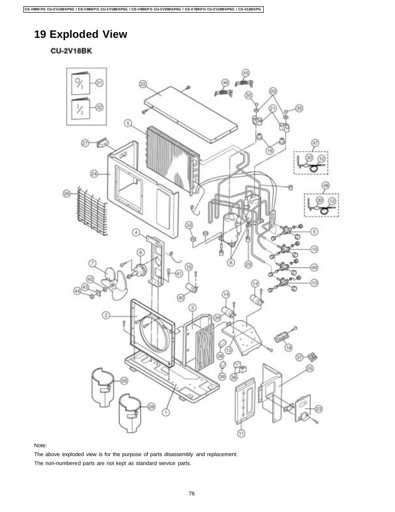
19 Exploded View
Note:The above exploded view is for the purpose of parts disassembly and replacement.The non-numbered parts are not kept as standard service parts.
76
CS-V9BKPG CU-2V14BKP5G / CS-V9BKP G CU-2V18BKP5G / CS-V9BKP G CU-3V20BKP5G / CS-V7BKP G CU-2V19BKP5G / CS-V12BKPG
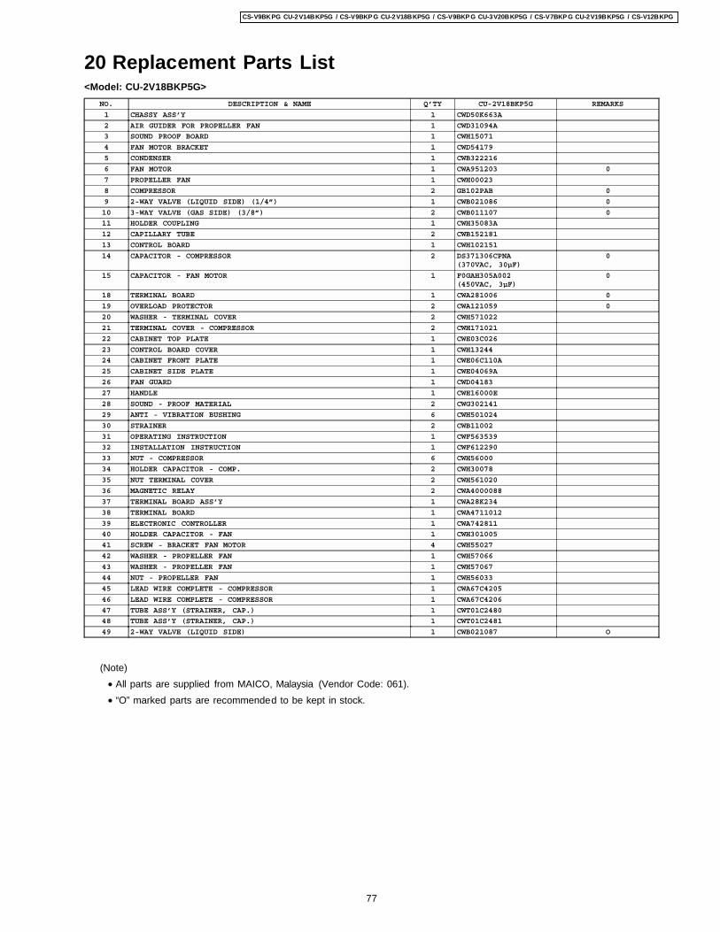
20 Replacement Parts List<Model: CU-2V18BKP5G>
NO. DESCRIPTION & NAME Q’TY CU-2V18BKP5G REMARKS
1 CHASSY ASS’Y 1 CWD50K663A
2 AIR GUIDER FOR PROPELLER FAN 1 CWD31094A
3 SOUND PROOF BOARD 1 CWH15071
4 FAN MOTOR BRACKET 1 CWD54179
5 CONDENSER 1 CWB322216
6 FAN MOTOR 1 CWA951203 0
7 PROPELLER FAN 1 CWH00023
8 COMPRESSOR 2 GB102PAB 0
9 2-WAY VALVE (LIQUID SIDE) (1/4”) 1 CWB021086 0
10 3-WAY VALVE (GAS SIDE) (3/8”) 2 CWB011107 0
11 HOLDER COUPLING 1 CWH35083A
12 CAPILLARY TUBE 2 CWB152181
13 CONTROL BOARD 1 CWH102151
14 CAPACITOR - COMPRESSOR 2 DS371306CPNA(370VAC, 30µF)
0
15 CAPACITOR - FAN MOTOR 1 F0GAH305A002(450VAC, 3µF)
0
18 TERMINAL BOARD 1 CWA281006 0
19 OVERLOAD PROTECTOR 2 CWA121059 0
20 WASHER - TERMINAL COVER 2 CWH571022
21 TERMINAL COVER - COMPRESSOR 2 CWH171021
22 CABINET TOP PLATE 1 CWE03C026
23 CONTROL BOARD COVER 1 CWH13244
24 CABINET FRONT PLATE 1 CWE06C110A
25 CABINET SIDE PLATE 1 CWE04069A
26 FAN GUARD 1 CWD04183
27 HANDLE 1 CWE16000E
28 SOUND - PROOF MATERIAL 2 CWG302141
29 ANTI - VIBRATION BUSHING 6 CWH501024
30 STRAINER 2 CWB11002
31 OPERATING INSTRUCTION 1 CWF563539
32 INSTALLATION INSTRUCTION 1 CWF612290
33 NUT - COMPRESSOR 6 CWH56000
34 HOLDER CAPACITOR - COMP. 2 CWH30078
35 NUT TERMINAL COVER 2 CWH561020
36 MAGNETIC RELAY 2 CWA4000088
37 TERMINAL BOARD ASS’Y 1 CWA28K234
38 TERMINAL BOARD 1 CWA4711012
39 ELECTRONIC CONTROLLER 1 CWA742811
40 HOLDER CAPACITOR - FAN 1 CWH301005
41 SCREW - BRACKET FAN MOTOR 4 CWH55027
42 WASHER - PROPELLER FAN 1 CWH57066
43 WASHER - PROPELLER FAN 1 CWH57067
44 NUT - PROPELLER FAN 1 CWH56033
45 LEAD WIRE COMPLETE - COMPRESSOR 1 CWA67C4205
46 LEAD WIRE COMPLETE - COMPRESSOR 1 CWA67C4206
47 TUBE ASS’Y (STRAINER, CAP.) 1 CWT01C2480
48 TUBE ASS’Y (STRAINER, CAP.) 1 CWT01C2481
49 2-WAY VALVE (LIQUID SIDE) 1 CWB021087 O
(Note) • All parts are supplied from MAICO, Malaysia (Vendor Code: 061). • “O” marked parts are recommended to be kept in stock.
77
CS-V9BKPG CU-2V14BKP5G / CS-V9BKP G CU-2V18BKP5G / CS-V9BKP G CU-3V20BKP5G / CS-V7BKP G CU-2V19BKP5G / CS-V12BKPG
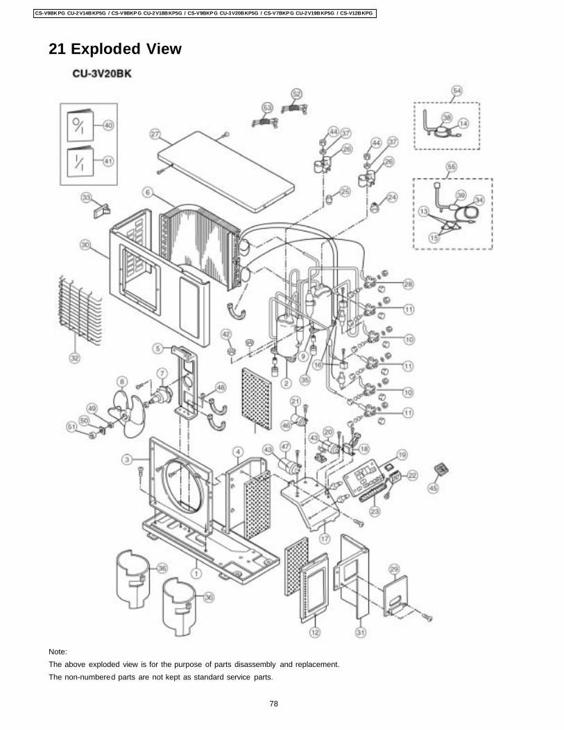
21 Exploded View
Note:The above exploded view is for the purpose of parts disassembly and replacement.The non-numbered parts are not kept as standard service parts.
78
CS-V9BKPG CU-2V14BKP5G / CS-V9BKP G CU-2V18BKP5G / CS-V9BKP G CU-3V20BKP5G / CS-V7BKP G CU-2V19BKP5G / CS-V12BKPG
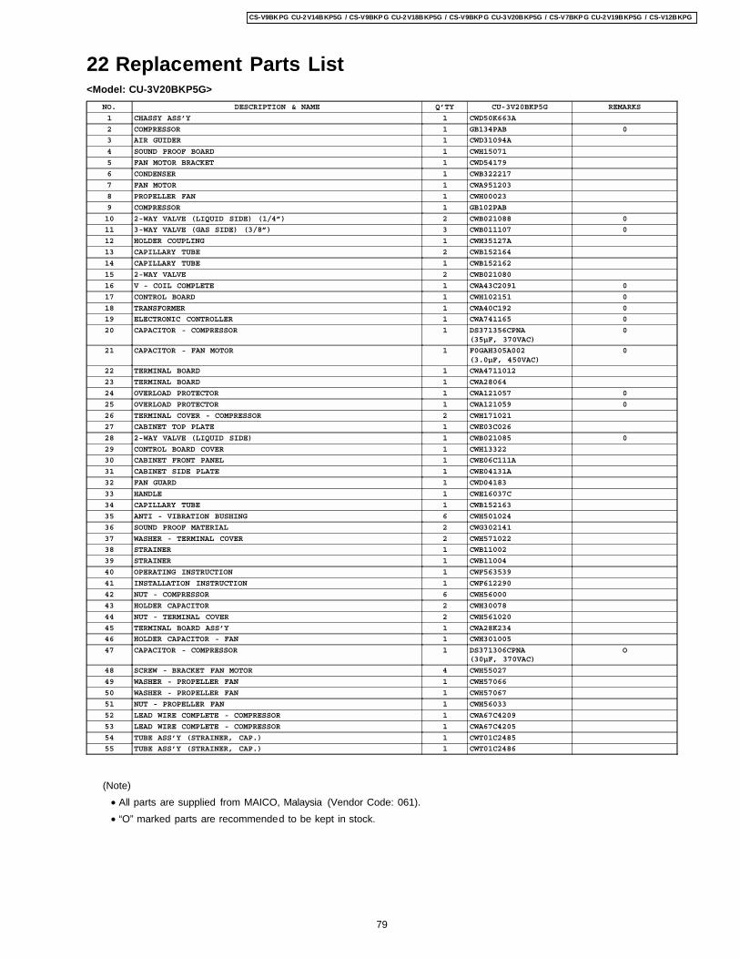
22 Replacement Parts List<Model: CU-3V20BKP5G>
NO. DESCRIPTION & NAME Q’TY CU-3V20BKP5G REMARKS
1 CHASSY ASS’Y 1 CWD50K663A
2 COMPRESSOR 1 GB134PAB 0
3 AIR GUIDER 1 CWD31094A
4 SOUND PROOF BOARD 1 CWH15071
5 FAN MOTOR BRACKET 1 CWD54179
6 CONDENSER 1 CWB322217
7 FAN MOTOR 1 CWA951203
8 PROPELLER FAN 1 CWH00023
9 COMPRESSOR 1 GB102PAB
10 2-WAY VALVE (LIQUID SIDE) (1/4”) 2 CWB021088 0
11 3-WAY VALVE (GAS SIDE) (3/8”) 3 CWB011107 0
12 HOLDER COUPLING 1 CWH35127A
13 CAPILLARY TUBE 2 CWB152164
14 CAPILLARY TUBE 1 CWB152162
15 2-WAY VALVE 2 CWB021080
16 V - COIL COMPLETE 1 CWA43C2091 0
17 CONTROL BOARD 1 CWH102151 0
18 TRANSFORMER 1 CWA40C192 0
19 ELECTRONIC CONTROLLER 1 CWA741165 0
20 CAPACITOR - COMPRESSOR 1 DS371356CPNA(35µF, 370VAC)
0
21 CAPACITOR - FAN MOTOR 1 F0GAH305A002(3.0µF, 450VAC)
0
22 TERMINAL BOARD 1 CWA4711012
23 TERMINAL BOARD 1 CWA28064
24 OVERLOAD PROTECTOR 1 CWA121057 0
25 OVERLOAD PROTECTOR 1 CWA121059 0
26 TERMINAL COVER - COMPRESSOR 2 CWH171021
27 CABINET TOP PLATE 1 CWE03C026
28 2-WAY VALVE (LIQUID SIDE) 1 CWB021085 0
29 CONTROL BOARD COVER 1 CWH13322
30 CABINET FRONT PANEL 1 CWE06C111A
31 CABINET SIDE PLATE 1 CWE04131A
32 FAN GUARD 1 CWD04183
33 HANDLE 1 CWE16037C
34 CAPILLARY TUBE 1 CWB152163
35 ANTI - VIBRATION BUSHING 6 CWH501024
36 SOUND PROOF MATERIAL 2 CWG302141
37 WASHER - TERMINAL COVER 2 CWH571022
38 STRAINER 1 CWB11002
39 STRAINER 1 CWB11004
40 OPERATING INSTRUCTION 1 CWF563539
41 INSTALLATION INSTRUCTION 1 CWF612290
42 NUT - COMPRESSOR 6 CWH56000
43 HOLDER CAPACITOR 2 CWH30078
44 NUT - TERMINAL COVER 2 CWH561020
45 TERMINAL BOARD ASS’Y 1 CWA28K234
46 HOLDER CAPACITOR - FAN 1 CWH301005
47 CAPACITOR - COMPRESSOR 1 DS371306CPNA(30µF, 370VAC)
O
48 SCREW - BRACKET FAN MOTOR 4 CWH55027
49 WASHER - PROPELLER FAN 1 CWH57066
50 WASHER - PROPELLER FAN 1 CWH57067
51 NUT - PROPELLER FAN 1 CWH56033
52 LEAD WIRE COMPLETE - COMPRESSOR 1 CWA67C4209
53 LEAD WIRE COMPLETE - COMPRESSOR 1 CWA67C4205
54 TUBE ASS’Y (STRAINER, CAP.) 1 CWT01C2485
55 TUBE ASS’Y (STRAINER, CAP.) 1 CWT01C2486
(Note) • All parts are supplied from MAICO, Malaysia (Vendor Code: 061). • “O” marked parts are recommended to be kept in stock.
79
CS-V9BKPG CU-2V14BKP5G / CS-V9BKP G CU-2V18BKP5G / CS-V9BKP G CU-3V20BKP5G / CS-V7BKP G CU-2V19BKP5G / CS-V12BKPG
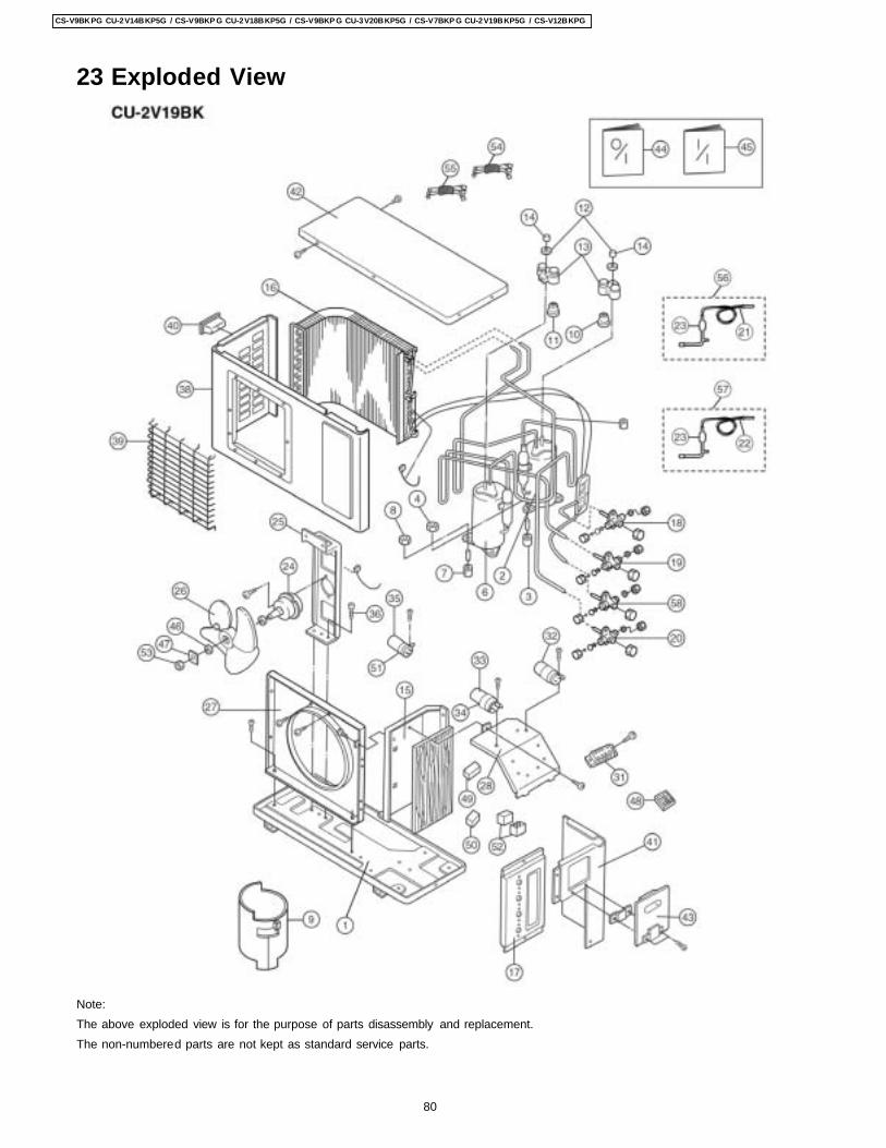
23 Exploded View
Note:The above exploded view is for the purpose of parts disassembly and replacement.The non-numbered parts are not kept as standard service parts.
80
CS-V9BKPG CU-2V14BKP5G / CS-V9BKP G CU-2V18BKP5G / CS-V9BKP G CU-3V20BKP5G / CS-V7BKP G CU-2V19BKP5G / CS-V12BKPG
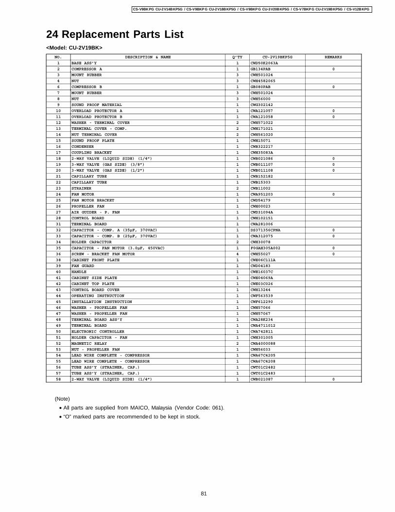
24 Replacement Parts List<Model: CU-2V19BK>
NO. DESCRIPTION & NAME Q’TY CU-2V19BKP5G REMARKS
1 BASE ASS’Y 1 CWD50K2063A
2 COMPRESSOR A 1 GB134PAB 0
3 MOUNT RUBBER 3 CWH501024
4 NUT 3 CWH4582065
6 COMPRESSOR B 1 GB080PAB 0
7 MOUNT RUBBER 3 CWH501024
8 NUT 3 CWH56000
9 SOUND PROOF MATERIAL 1 CWG302142
10 OVERLOAD PROTECTOR A 1 CWA121057 0
11 OVERLOAD PROTECTOR B 1 CWA121058 0
12 WASHER - TERMINAL COVER 2 CWH571022
13 TERMINAL COVER - COMP. 2 CWH171021
14 NUT TERMINAL COVER 2 CWH561020
15 SOUND PROOF PLATE 1 CWH15071
16 CONDENSER 1 CWB322217
17 COUPLING BRACKET 1 CWH35083A
18 2-WAY VALVE (LIQUID SIDE) (1/4”) 1 CWB021086 0
19 3-WAY VALVE (GAS SIDE) (3/8”) 1 CWB011107 0
20 3-WAY VALVE (GAS SIDE) (1/2”) 1 CWB011108 0
21 CAPILLARY TUBE 1 CWB152182
22 CAPILLARY TUBE 1 CWB15303
23 STRAINER 2 CWB11002
24 FAN MOTOR 1 CWA951203 0
25 FAN MOTOR BRACKET 1 CWD54179
26 PROPELLER FAN 1 CWH00023
27 AIR GUIDER - P. FAN 1 CWD31094A
28 CONTROL BOARD 1 CWH102151
31 TERMINAL BOARD 1 CWA281006
32 CAPACITOR - COMP. A (35µF, 370VAC) 1 DS371356CPNA 0
33 CAPACITOR - COMP. B (25µF, 370VAC) 1 CWA312075 0
34 HOLDER CAPACITOR 2 CWH30078
35 CAPACITOR - FAN MOTOR (3.0µF, 450VAC) 1 F0GAH305A002 0
36 SCREW - BRACKET FAN MOTOR 4 CWH55027 0
38 CABINET FRONT PLATE 1 CWE06C111A
39 FAN GUARD 1 CWD04183
40 HANDLE 1 CWE16037C
41 CABINET SIDE PLATE 1 CWE04069A
42 CABINET TOP PLATE 1 CWE03C026
43 CONTROL BOARD COVER 1 CWH13244
44 OPERATING INSTRUCTION 1 CWF563539
45 INSTALLATION INSTRUCTION 1 CWF612290
46 WASHER - PROPELLER FAN 1 CWH57066
47 WASHER - PROPELLER FAN 1 CWH57067
48 TERMINAL BOARD ASS’Y 1 CWA28K234
49 TERMINAL BOARD 1 CWA4711012
50 ELECTRONIC CONTROLLER 1 CWA742811
51 HOLDER CAPACITOR - FAN 1 CWH301005
52 MAGNETIC RELAY 2 CWA4000088
53 NUT - PROPELLER FAN 1 CWH56033
54 LEAD WIRE COMPLETE - COMPRESSOR 1 CWA67C4205
55 LEAD WIRE COMPLETE - COMPRESSOR 1 CWA67C4208
56 TUBE ASS’Y (STRAINER, CAP.) 1 CWT01C2482
57 TUBE ASS’Y (STRAINER, CAP.) 1 CWT01C2483
58 2-WAY VALVE (LIQUID SIDE) (1/4”) 1 CWB021087 0
(Note) • All parts are supplied from MAICO, Malaysia (Vendor Code: 061). • “O” marked parts are recommended to be kept in stock.
81
CS-V9BKPG CU-2V14BKP5G / CS-V9BKP G CU-2V18BKP5G / CS-V9BKP G CU-3V20BKP5G / CS-V7BKP G CU-2V19BKP5G / CS-V12BKPG
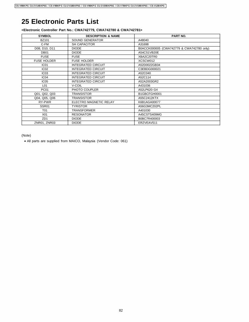
25 Electronic Parts List<Electronic Controller Part No.: CWA742779, CWA742780 & CWA742781>
SYMBOL DESCRIPTION & NAME PART NO.BZ101 SOUND GENERATOR A48040C-FM SH CAPACITOR A31698
D08, D10, D11 DIODE B0ACCK000005 (CWA742779 & CWA742780 only)DB01 DIODE A54CS1VB20EFUSE FUSE XBA2C20TR0
FUSE HOLDER FUSE HOLDER XCSCW012IC01 INTEGRATED CIRCUIT A52D0022GB34IC02 INTEGRATED CIRCUIT C3EBDG000021IC03 INTEGRATED CIRCUIT A52C040IC04 INTEGRATED CIRCUIT A52C114IC05 INTEGRATED CIRCUIT A52A2003GR2L01 V-COIL A431036
PC01 PHOTO COUPLER A52LP620-G4Q01, Q02, Q03 TRANSISTOR B1GBCFGH0001Q04, Q05, Q06 TRANSISTOR A55C2412KTX
RY-PWR ELECTRO MAGNETIC RELAY K6B1AGA00077SSR01 TYRISTOR A56G3MC202PL
T01 TRANSFORMER A401030X01 RESONATOR A45CSTS409MGZD1 DIODE B0BC7R400003
ZNR01, ZNR03 DIODE ERZVEAV511
(Note) • All parts are supplied from MAICO, Malaysia (Vendor Code: 061)
82
CS-V9BKPG CU-2V14BKP5G / CS-V9BKP G CU-2V18BKP5G / CS-V9BKP G CU-3V20BKP5G / CS-V7BKP G CU-2V19BKP5G / CS-V12BKPG
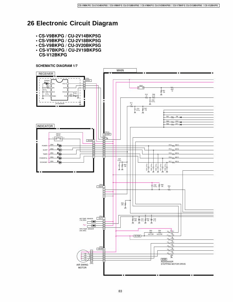
26 Electronic Circuit Diagram
SCHEMATIC DIAGRAM 1/7
• CS-V9BKPG / CU-2V14BKP5G• CS-V9BKPG / CU-2V18BKP5G• CS-V9BKPG / CU-3V20BKP5G• CS-V7BKPG / CU-2V19BKP5G
CS-V12BKPG
(PH10)
10 7
12 5
11 6
9
g
f
e
CN-STM
3
4
55
4
3
2
(PH5)
(ZH5)
AIR TEMP. SENSOR(15k 3950)
(20k 3950)PIPE TEMP. SENSOR
RECEIVER
INDICATOR
a
b
c
d
CN-DISP
7
6
5
4
3
1
2
1
8
314
215
116
413
(PH4)
IC05A52A2003GRSTEPPING MOTOR DRIVE
0.1µC08
–
+15kR33
0.01µC22
10kR58
1kR59
R04
R3020k
+
–C040.1µ
(CR3)
PH302C
330
0.01µ
0.01µFO
VCC2
OUT
VCC1
GND
CO
IN-
IN+
47µ6.3V
–+
137k
µPC2800AGR
5
6
7
8
4
3
2
1
CN-RCV
CN-DISP
2
3
4
5
6
7
8
10
9
CN-TH
1
2
MAIN
AIR SWINGMOTOR
SW101AUTO
10kR60
(XH4)
CN-HA
0.01µC23
430R13
620R14
620R15
620R16
430R17
C28
0.0
1µ
C27
0.0
1µ
C26
0.0
1µ
C25
0.0
1µ
C24
0.0
1µ
43 /2W
R05
43 /2WRY-PWR
D10
D11
D8
R23
R24
R21
24kR06
1kR11
0.01µC01
10kR07
5.1kR08
1kR12
0.01µC02
TEST
R021kR01
10k
ECONOMY
POWER
TIMER
SLEEP
POWERFUL
GRN
1 2
ORG
ORG
GRN
ORG
1
3
2
3
4
1
2
1
83
CS-V9BKPG CU-2V14BKP5G / CS-V9BKP G CU-2V18BKP5G / CS-V9BKP G CU-3V20BKP5G / CS-V7BKP G CU-2V19BKP5G / CS-V12BKPG
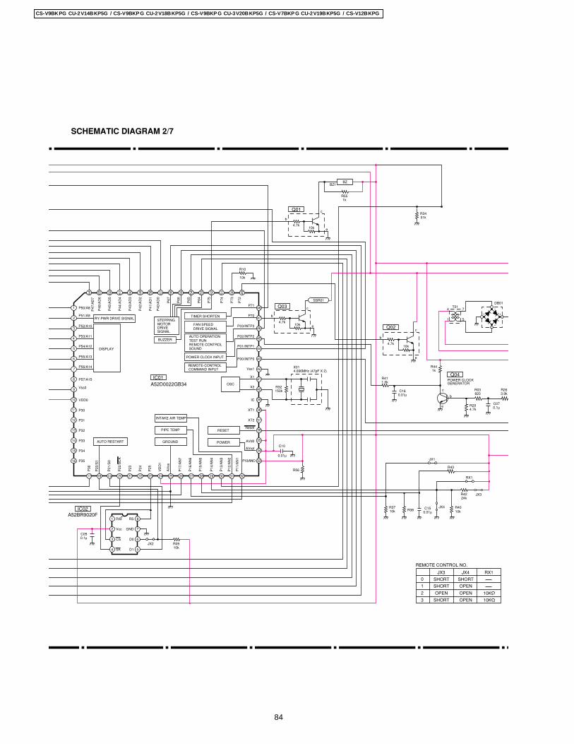
Q03
4.7k10k e
b
c
DB01T01
4 7
51
A52D0022GB34IC01
+–
~
~
P72
P73
P74
P75
P64
P65
P66
P67
P40
/AD
0
P41
/AD
1
P42
/AD
2
P43
/AD
3
P44
/AD
4
P45
/AD
5
P46
/AD
6
P47
/AD
7
P11
/AN
1
P12
/AN
2
P13
/AN
3
P14
/AN
4
P15
/AN
5
P16
/AN
6
P17
/AN
7
AV
ss
VD
D1
P25
P24
P23
P22
/SC
K
P21
/S0
P20
/S1
P36
P51/A9
P50/A8
P53/A11
P52/A10
P54/A12
P56/A14
P55/A13
P57/A15
VDD0
Vss0
P31
P30
P32
P34
P35
P33
46
41
42
43
44
45
64 63 62 61 60 59 58 57 56 55 54 53 52 51 50 49
48
47
40
39
38
37
36
35
33
32313029282726252423222120191817
16
15
14
13
12
11
9
8
7
6
5
4
3
2
1
P02/INTP2
P01/INTP1
P00/INTP0
P70
P71
P03/INTP3
Vss1
X1
X2
IC
XT1
XT2
Reset
AVref
P10/ANO
AVd0
R10
10k
150kR32
X014.096MHz (47pF X 2)
0.01µ
C10
R56
IC02A52BR9020F
5
6
8
3
1 RS
D0
D1
R/B
CS
SK4
Vcc GND 7C050.1µ
10kR09JX2
Q02
4.7k10k
e
b
c
Q04
c
e
b
R441k
1.0kR41
820R03
4.7kR29
3.9kR26
0.1µC07
GENERATORPOWER CLOCK
0.01µC16
10kR37
0.01µC15 JX4
R38 10kR40
JX324kR42
RX1
R43
JX1
Q01
4.7k10k e
b
c
BZ1BZ
1kR55
51kR34
DISPLAY
GROUNDAUTO RESTART POWER
RESETPIPE TEMP
INTAKE AIR TEMP
OSC
REMOTE-CONTROL
POWER CLOCK INPUT
DRIVE SIGNALFAN SPEED
BUZZER
COMMAND INPUT
SIGNALDRIVEMOTORSTEPPINGRY-PWR DRIVE SIGNAL
AUTO OPERATION TEST RUN REMOTE CONTROL SOUND
TIMER SHORTEN
REMOTE CONTROL NO.
SHORT
SHORT
OPEN
SHORT
SHORT
OPEN
OPEN
OPEN
1
0
3
2
JX3 JX4 RX1
10K
10K
2
SSR01
34
10
SCHEMATIC DIAGRAM 2/7
84
CS-V9BKPG CU-2V14BKP5G / CS-V9BKP G CU-2V18BKP5G / CS-V9BKP G CU-3V20BKP5G / CS-V7BKP G CU-2V19BKP5G / CS-V12BKPG
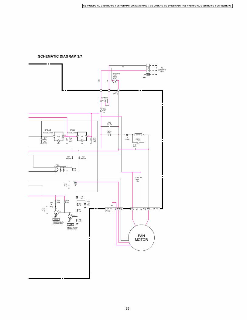
IC03
G
I
16V100µC11
–
+5V12VI
G
IC04
C173300µ35V
(NHG)
+
–
+
–
C14470µ25V
1kR36
MOTORFAN
CN-FM543132CN-FB1 1
(PH-3)
RY-PWR
250V2A
AC
THERMALFUSE102°C
TOOUTDOOR
UNIT
(WHT)
511UZNR01
REGULATOR REGULATOR
0.1µC12
400V1.5µ
C-FM
0.047µC03
SSR01
511UZNR03125µH
L01
0.47µC19
510R48
39k/2WR47
39k/2WR57
3
4 1
2
PC01
0.1µC18 c
e
b
R50100kR49
1k
R5110k
c
e
b
6.2kR54
10kR53
6.2kR52
ZD17.5EL1
Q05
Q06
50V10µC21
–
+
GENERATIONRESET SIGNAL
GENERATIONRESET SIGNAL
2
FUSE
O O
BR
BL
W1
2
3
SCHEMATIC DIAGRAM 3/7
85
CS-V9BKPG CU-2V14BKP5G / CS-V9BKP G CU-2V18BKP5G / CS-V9BKP G CU-3V20BKP5G / CS-V7BKP G CU-2V19BKP5G / CS-V12BKPG
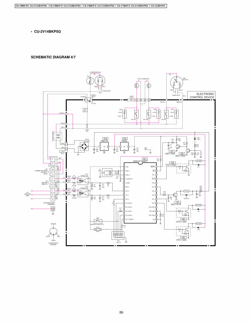
OLP
COMPRESSOR AYEL
RED
CAPACITOR
BLU
BLU
1
3
COMP-A(WHT)AC(WHT)
RY-CA
FUSE3.15A250V
AC(BLU)
T(BLK)
T(BLK)
ZNR1511
P L
CR2
Ω120
0.033
RY-VA1 RY-VA2
FM(YEL) FM(BLU)
BLU
YEL
FANMOTOR
BLURED
CAPACITOR
CR3
Ω120
0.033
RY-FM
CR1
Ω120
0.033
CN-V
(GRN)VH7-4
1 3 7
V-COIL COMPLETEA B
I O
G
12V I O
G
5V
IC378M12H
IC278N05
IC1A52C401828CP
Q72SC1740S Q6
2SC1740S
Q3DTC113ZS
Q4DTC113ZS
Q5DTC113ZS
Q12SC1741R
C1220035V
C247025V
C310016V
R1310k
R15150k
X14KHz
GND
DB101S1VB20
R161k
R28100k
R256.8k
R710k
R81k
C91016V
C120.01
R192.2k
R1410k
R2010k
R266.2k
1k 10k
1k 10k
1k 10k
D7RA15-01
C60.01
C547035V
R23Ω822W
C71
50V
R2710k
ZD17.5EL1
RY-CA
D11
RY-FM
D9
RY-VA2
D10
RY-VA1
1
2
3
4
5
6
7
8
9
10
11
12
13
14
28
27
26
25
24
23
22
21
20
19
18
17
16
15
RESET
IRQ
PA 7
PA 6
PA 5
PA 4
PA 3
PA 2
PA 1
PA 0
PB 5/SDO
PB 6/SDI
PB 7/SCK
Vss
Vdd
OSC 1
OSC 2
TCAP/PD 7
TCMP
PD 5
PC 0
PC 1
PC 2
PC 3/AD 3
PC 4/AD 2
PC 5/AD 1
PC 6/AD 0
PC 7/VREFH
A1
A1
(RED)AC
R147k 2W
R247k 2W
1
2
4
PC1TLP620-1G4
3(RED)
AC
R910k
R101k
R171k
R181k
RA110k x 5
C101016V
A2
A2
(BLUE)AC
R347k 2W
R447k 2W
1
2
4
PC2TLP620-1G4
3(BLUE)
AC
J2
12
SW1
MANUAL AUTO
TEST
NH-2
RED
RED
CN-T
VH-2
TR
AN
SF
OR
ME
R
L
N
1
2
1
2
3
1
TOPOWER SOURCE
AC 230 V50 Hz
TOINDOORUNIT A1
TOINDOOR
UNIT
OUTDOOR UNITTERMINAL
WHT
WH
TW
HT
BLK
BLU
BLU
ELECTRONICCONTROL DEVICE
5
2
3
BLUE RED
MARK
COMPRESSORTERMINAL
BROWN
• CU-2V14BKP5G
SCHEMATIC DIAGRAM 4/7
86
CS-V9BKPG CU-2V14BKP5G / CS-V9BKP G CU-2V18BKP5G / CS-V9BKP G CU-3V20BKP5G / CS-V7BKP G CU-2V19BKP5G / CS-V12BKPG
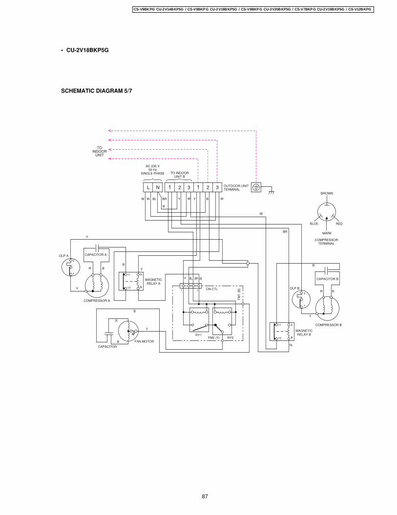
• CU-2V18BKP5G
BLUE RED
MARK
COMPRESSORTERMINAL
BROWN
AC 230 V50 Hz
SINGLE PHASE TO INDOORUNIT B
OUTDOOR UNITTERMINALL N 1 2 3 1 2 3
TOINDOOR
UNIT
OLP A
OLP B
Y
Y
Y
Y
CAPACITOR A
CAPACITOR
FAN MOTOR
RY1RY2
CN-CTL
FM2 (Y)
FM
1 (B
)
COMPRESSOR A
CAPACITOR B
COMPRESSOR B
MAGNETICRELAY A
MAGNETICRELAY B
R
R
B
R B
B
B
B
B
W
Y
Y Y
Y
W
W
WWBL
B
B
BBR
BR
BL BR
3
11
1 7
A
B12
11
3
1
A
B
BL
12
1
SCHEMATIC DIAGRAM 5/7
87
CS-V9BKPG CU-2V14BKP5G / CS-V9BKP G CU-2V18BKP5G / CS-V9BKP G CU-3V20BKP5G / CS-V7BKP G CU-2V19BKP5G / CS-V12BKPG
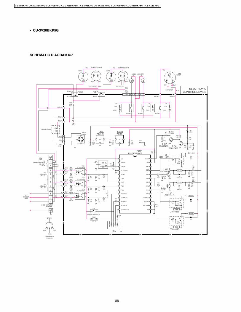
• CU-3V20BKP5G
3
1
OLP A OLP B
COMPRESSOR A COMPRESSOR BYEL
RED
CAPACITOR CAPACITOR
BLU RED BLU
BLUBLU
COMP-B(YEL)
COMP-A(WHT)
AC(WHT)
RY-CA
FUSE3.15A250V
AC(BLU)
T(BLK)
T(BLK)
ZNR1511
P L PL
RY-CB
CR2
Ω120
0.033
RY-VA1 RY-VA2
FM(YEL) FM(BLU)
BLU
YEL
FANMOTOR
BLUGRY
CAPACITOR
CR3
Ω120
0.033
RY-FM
CR1
Ω120
0.033
YEL
CN-V
(GRN)VH7-4
1 3 7
V-COIL COMPLETEA B
I O
G
12V I O
G
5V
IC378M12H
IC278N05
IC1A52C401828CP
Q72SC1740S Q6
2SC1740S
Q3DTC113ZS
Q4DTC113ZS
Q5DTC113ZS
Q22SC1741R
Q12SC1741R
C1220035V
C247025V
C310016V
R1310k
R15150k
X14KHz
GND
DB101S1VB20
R161k
R28100k
R256.8k
R2210k
R710k
R81k
C91016V
C120.01
R212.2k
R192.2k
R1410k
R2010k
R266.2k
1k 10k
1k 10k
1k 10k
D8RA15-01
D7RA15-01
C60.01
C447050V
C547035V
R24Ω822W
R23Ω822W
C71
50V
R2710k
ZD17.5EL1
RY-CA
RY-CB
D11
RY-FM
D9
RY-VA2
D10
RY-VA1
1
2
3
4
5
6
7
8
9
10
11
12
13
14
27
26
25
24
23
22
21
20
19
18
17
16
15
RESET
IRQ
PA 7
PA 6
PA 5
PA 4
PA 3
PA 2
PA 1
PA 0
PB 5/SDO
PB 6/SDI
PB 7/SCK
Vss
Vdd
OSC 1
OSC 2
TCAP/PD 7
TCMP
PD 5
PC 0
PC 1
PC 2
PC 3/AD 3
PC 4/AD 2
PC 5/AD 1
PC 6/AD 0
PC 7/VREFH
A1
A1
(RED)AC
R147k 2W
R247k 2W
1
2
4
PC1TLP620-1G4
3(RED)
AC
R910k
R101k
R171k
R181k
RA110k x 5
C101016V
A2
A2
(BLUE)AC
R347k 2W
R447k 2W
1
2
4
PC2TLP620-1G4
3(BLUE)
AC
R1110k
R121k
C111016V
B
B
(YEL)AC
R547k 2W
R647k 2W
1
2
4
PC3TLP620-1G4
3(YEL)
AC
J2
12
SW1
MANUAL AUTO
TEST
NH-2
RED
RED
CN-T
VH-2
TRANSFORMER
L
N
1
2
3
1
2
3
1
2
3
TOPOWER SOURCE
AC 230 V50 Hz
TOINDOORUNIT A1
TOINDOORUNIT A2
TOINDOOR
UNIT
OUTDOOR UNITTERMINAL
WH
T
WH
TW
HT
BLK
BLK
BLK
BLU
ELECTRONICCONTROL DEVICE
5
28
BLUE RED
MARK
COMPRESSORTERMINAL
BROWN
3
1
SCHEMATIC DIAGRAM 6/7
88
CS-V9BKPG CU-2V14BKP5G / CS-V9BKP G CU-2V18BKP5G / CS-V9BKP G CU-3V20BKP5G / CS-V7BKP G CU-2V19BKP5G / CS-V12BKPG
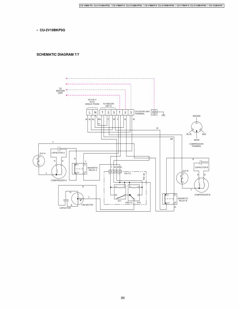
BLUE RED
MARK
COMPRESSORTERMINAL
BROWN
AC 230 V50 Hz
SINGLE PHASE TO INDOORUNIT B
OUTDOOR UNITTERMINALL N 1 2 3 1 2 3
TOINDOOR
UNIT
OLP A
OLP B
Y
Y
Y
Y
CAPACITOR A
CAPACITOR
FAN MOTOR
RY1RY2
CN-CTL
FM2 (Y)
FM
1 (B
)
COMPRESSOR A
CAPACITOR B
COMPRESSOR B
MAGNETICRELAY A
MAGNETICRELAY B
R
R
B
R B
B
B
B
B
W
Y
Y Y
Y
W
W
WWBL
B
B
BBR
BR
BL BR11
1 7
A
B12
11 A
B
BL
12
1
3
1
3
SCHEMATIC DIAGRAM 7/7
• CU-2V19BKP5G
89
CS-V9BKPG CU-2V14BKP5G / CS-V9BKP G CU-2V18BKP5G / CS-V9BKP G CU-3V20BKP5G / CS-V7BKP G CU-2V19BKP5G / CS-V12BKPG
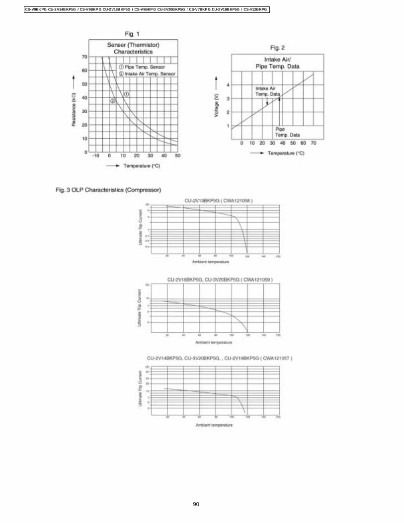
90
CS-V9BKPG CU-2V14BKP5G / CS-V9BKP G CU-2V18BKP5G / CS-V9BKP G CU-3V20BKP5G / CS-V7BKP G CU-2V19BKP5G / CS-V12BKPG
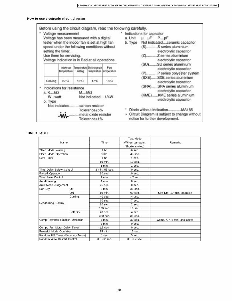
How to use electronic circuit diagram
TIMER TABLETest Mode
Name Time (When test point RemarksShort-circuited)
Sleep Mode Waiting 1 hr. 6 sec.Sleep Mode Operation 8 hrs. 48 sec.Real Timer 1 hr. 1 min.
10 min. 10 sec.1 min. 1 sec.
Time Delay Safety Control 2 min. 58 sec. 0 sec.Forced Operation 60 sec. 0 sec.Time Save Control 7 min. 4.2 sec.Anti-Freezing 4 min. 0 sec.Auto Mode Judgement 25 sec. 0 sec.Soft Dry OFF 6 min. 36 sec.
ON 10 min. 60 sec. Soft Dry: 10 min. operation
Deodorizing Control
Cooling 40 sec. 4 sec.70 sec. 7 sec.20 sec. 2 sec.
180 sec. 18 sec.Soft Dry 40 sec. 4 sec.
360 sec. 36 sec.Comp. Reverse Rotation Detection 5 min. 30 sec. Comp. ON 5 min. and above
2 min. 0 sec.Comp./ Fan Motor Delay Timer 1.6 sec. 0 sec.Powerful Mode Operation 15 min. 15 sec.Random FM Timer (Economy Mode) 5 sec. 5 sec.Random Auto Restart Control 0 ~ 62 sec. 0 ~ 6.2 sec.
91
CS-V9BKPG CU-2V14BKP5G / CS-V9BKP G CU-2V18BKP5G / CS-V9BKP G CU-3V20BKP5G / CS-V7BKP G CU-2V19BKP5G / CS-V12BKPG
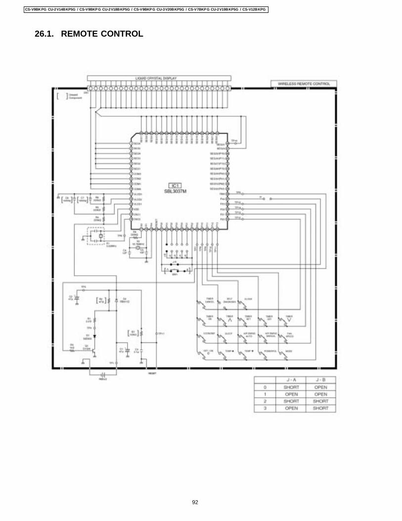
26.1. REMOTE CONTROL
92
CS-V9BKPG CU-2V14BKP5G / CS-V9BKP G CU-2V18BKP5G / CS-V9BKP G CU-3V20BKP5G / CS-V7BKP G CU-2V19BKP5G / CS-V12BKPG
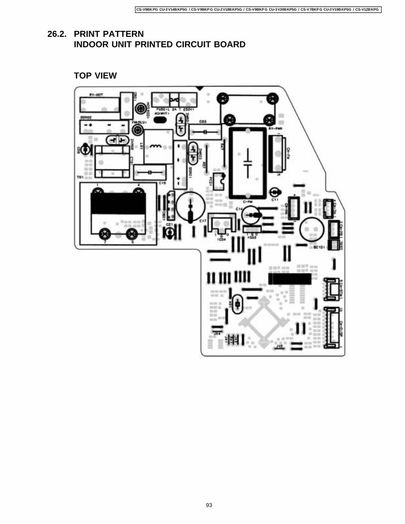
26.2. PRINT PATTERNINDOOR UNIT PRINTED CIRCUIT BOARD
TOP VIEW
93
CS-V9BKPG CU-2V14BKP5G / CS-V9BKP G CU-2V18BKP5G / CS-V9BKP G CU-3V20BKP5G / CS-V7BKP G CU-2V19BKP5G / CS-V12BKPG
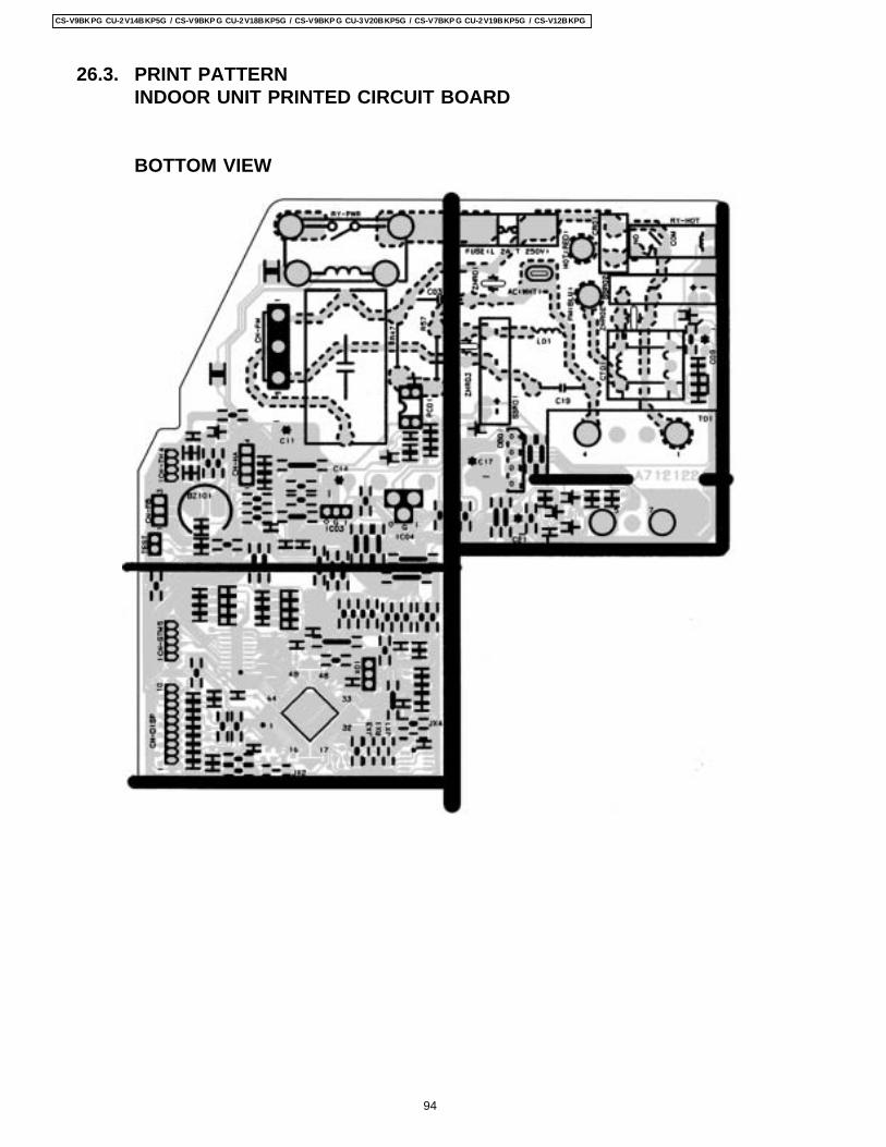
26.3. PRINT PATTERNINDOOR UNIT PRINTED CIRCUIT BOARD
BOTTOM VIEW
94
CS-V9BKPG CU-2V14BKP5G / CS-V9BKP G CU-2V18BKP5G / CS-V9BKP G CU-3V20BKP5G / CS-V7BKP G CU-2V19BKP5G / CS-V12BKPG
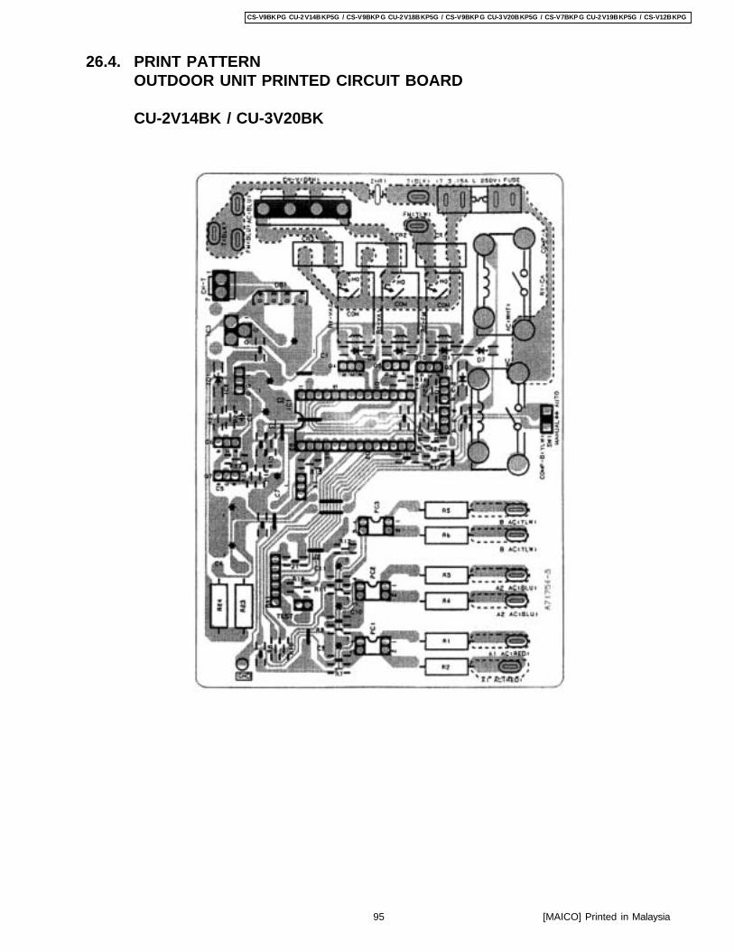
26.4. PRINT PATTERNOUTDOOR UNIT PRINTED CIRCUIT BOARD
CU-2V14BK / CU-3V20BK
95
CS-V9BKPG CU-2V14BKP5G / CS-V9BKP G CU-2V18BKP5G / CS-V9BKP G CU-3V20BKP5G / CS-V7BKP G CU-2V19BKP5G / CS-V12BKPG
[MAICO] Printed in Malaysia