Embed Size (px)
Citation preview

TECHNICAL REPORT
© The Broadband Forum. All rights reserved.
TR-178
Multi-service Broadband Network Architecture and Nodal Requirements
Issue: 1
Issue Date: September 2014

Multi-service Broadband Network Architecture and Nodal Requirements TR-178 Issue 1
September 2014 © The Broadband Forum. All rights reserved 2 of 97
Notice
The Broadband Forum is a non-profit corporation organized to create guidelines for broadband
network system development and deployment. This Broadband Forum Technical Report has
been approved by members of the Forum. This Broadband Forum Technical Report is not
binding on the Broadband Forum, any of its members, or any developer or service provider. This
Broadband Forum Technical Report is subject to change, but only with approval of members of
the Forum. This Technical Report is copyrighted by the Broadband Forum, and all rights are
reserved. Portions of this Technical Report may be copyrighted by Broadband Forum members.
THIS SPECIFICATION IS BEING OFFERED WITHOUT ANY WARRANTY
WHATSOEVER, AND IN PARTICULAR, ANY WARRANTY OF NONINFRINGEMENT IS
EXPRESSLY DISCLAIMED. ANY USE OF THIS SPECIFICATION SHALL BE MADE
ENTIRELY AT THE IMPLEMENTER'S OWN RISK, AND NEITHER the Forum, NOR ANY
OF ITS MEMBERS OR SUBMITTERS, SHALL HAVE ANY LIABILITY WHATSOEVER
TO ANY IMPLEMENTER OR THIRD PARTY FOR ANY DAMAGES OF ANY NATURE
WHATSOEVER, DIRECTLY OR INDIRECTLY, ARISING FROM THE USE OF THIS
SPECIFICATION.
Broadband Forum Technical Reports may be copied, downloaded, stored on a server or
otherwise re-distributed in their entirety only, and may not be modified without the advance
written permission of the Broadband Forum.
The text of this notice must be included in all copies of this Broadband Forum Technical Report.

Multi-service Broadband Network Architecture and Nodal Requirements TR-178 Issue 1
September 2014 © The Broadband Forum. All rights reserved 3 of 97
Issue History
Issue
Number
Approval Date Publication
Date
Issue Editor Changes
1 8 September
2014
27 October
2014
Christophe Alter, Orange
Yves Hertoghs, Cisco
Hongyu Li, Huawei Technologies
Jaume Rius i Riu, Ericsson
Original
Comments or questions about this Broadband Forum Technical Report should be directed to
Editors Alter, Christophe Orange
Hertoghs, Yves Cisco
Li, Hongyu Huawei Technologies
Rius i Riu, Jaume Ericsson
End to End Architecture
Working Group Co-Chairs
Dave Thorne
Dave Allan
BT
Ericsson
Vice Chair Sven Ooghe Alcatel-Lucent

Multi-service Broadband Network Architecture and Nodal Requirements TR-178 Issue 1
September 2014 © The Broadband Forum. All rights reserved 4 of 97
TABLE OF CONTENTS
TABLE OF CONTENTS ............................................................................................................. 4
1 PURPOSE AND SCOPE ...................................................................................... 9
1.1 PURPOSE .......................................................................................................................... 9
1.2 SCOPE .............................................................................................................................. 9
2 REFERENCES AND TERMINOLOGY .......................................................... 10
2.1 CONVENTIONS ............................................................................................................... 10
2.2 REFERENCES .................................................................................................................. 10
2.3 DEFINITIONS .................................................................................................................. 17
2.4 ABBREVIATIONS ............................................................................................................ 18
3 TECHNICAL REPORT IMPACT ................................................................... 21
3.1 ENERGY EFFICIENCY ...................................................................................................... 21
3.2 IPV6 ............................................................................................................................... 21
3.3 SECURITY ....................................................................................................................... 21
3.4 PROVISIONING................................................................................................................ 21
4 OVERVIEW OF FUNDAMENTAL ARCHITECTURES AND
TOPOLOGIES ............................................................................................................................ 22
4.1 DEPLOYMENT OPTIONS .................................................................................................. 22
4.2 THE ETHERNET SERVICE LAYER .................................................................................... 23
4.2.1 L2 NSP wholesale model .......................................................................................... 24
4.2.2 Network Termination at the Customer Premise........................................................ 25
4.2.3 Ethernet Wholesale QoS Architecture ...................................................................... 26
4.2.4 Ethernet Wholesale Service Classes ......................................................................... 26
4.2.5 Access Line Sharing .................................................................................................. 27
4.2.6 Ethernet Wholesale Port Types ................................................................................. 28
4.2.7 Multicast wholesale services..................................................................................... 29
4.2.8 Ethernet OAM ........................................................................................................... 29
4.3 THE REACH OF MPLS .................................................................................................... 35
4.3.1 Seamless MPLS ......................................................................................................... 35
4.3.2 Access Node Options with MPLS capabilities .......................................................... 36
4.4 TR-178 ARCHITECTURAL OPTIONS ................................................................................. 38
4.4.1 Fixed Broadband Access........................................................................................... 38
4.4.2 Mobile Backhaul ....................................................................................................... 42
4.4.3 Hierarchical QoS ...................................................................................................... 45
5 ACCESS NODE REQUIREMENTS ................................................................ 48
5.1 ACCESS NODES TYPES ................................................................................................... 49
5.2 ACCESS NODE DEPLOYMENT SCENARIOS ....................................................................... 49
5.3 NETWORK LINE INTERFACE REQUIREMENTS ................................................................. 51
5.3.1 Ethernet Interfaces .................................................................................................... 52
5.3.2 Passive WDM interfaces ........................................................................................... 53
5.3.3 Wavelength interfaces ............................................................................................... 53
5.3.4 PON interfaces .......................................................................................................... 53

Multi-service Broadband Network Architecture and Nodal Requirements TR-178 Issue 1
September 2014 © The Broadband Forum. All rights reserved 5 of 97
5.4 ETHERNET ACCESS NODE REQUIREMENTS .................................................................... 53
5.4.1 VLAN Tagging at the UNI......................................................................................... 53
5.4.2 Maximum frame size ................................................................................................. 56
5.4.3 QoS, Traffic Classification and Class of Service Based Forwarding ....................... 56
5.4.4 OAM .......................................................................................................................... 59
5.4.5 Resilience .................................................................................................................. 61
5.4.6 Multicast ................................................................................................................... 61
5.4.7 DHCP/PPPoE Processing ........................................................................................ 64
5.4.8 Security ..................................................................................................................... 65
5.5 MPLS ENABLED ACCESS NODE REQUIREMENTS ........................................................... 69
5.5.1 General Requirements .............................................................................................. 69
5.5.2 Layer 2 Requirements ............................................................................................... 70
5.5.3 Load Balancing ......................................................................................................... 71
5.5.4 Resilience .................................................................................................................. 71
5.5.5 OAM .......................................................................................................................... 72
5.5.6 QoS ............................................................................................................................ 73
5.5.7 MPLS related multicast requirements ...................................................................... 73
5.6 BNG EMBEDDED ACCESS NODE REQUIREMENTS .......................................................... 73
5.6.1 PSN tunnel related features ...................................................................................... 74
5.6.2 Additional L2 service related features ...................................................................... 75
5.6.3 L3 service related features for the Access Node ....................................................... 76
5.6.4 Synchronization......................................................................................................... 78
6 ETHERNET AGGREGATION NODE REQUIREMENTS .......................... 79
7 MULTI-SERVICE BROADBAND NETWORK GATEWAY (MS-BNG)
REQUIREMENTS ...................................................................................................................... 80
7.1 GENERIC MS-BNG REQUIREMENTS ............................................................................... 80
7.1.1 Policy Enforcement Capabilities .............................................................................. 80
7.1.2 Traffic Management .................................................................................................. 83
7.1.3 OAM .......................................................................................................................... 83
7.1.4 Hierarchical QoS Requirements ............................................................................... 84
7.1.5 VLAN Classification.................................................................................................. 85
7.1.6 Traffic filtering and QoS ........................................................................................... 87
7.1.7 Synchronization......................................................................................................... 88
7.1.8 Resilience .................................................................................................................. 89
7.1.9 AAA requirements for residential and business services .......................................... 89
7.2 ADDITIONAL MS-BNG REQUIREMENTS WHEN DEPLOYED AT THE EDGE IN A HIERARCHY
90
7.2.1 Traffic Management .................................................................................................. 90
7.2.2 OAM .......................................................................................................................... 90
7.2.3 Signaling ................................................................................................................... 90
7.3 ADDITIONAL MS-BNG REQUIREMENTS WHEN DEPLOYED CENTRALLY EITHER
STANDALONE OR IN A HIERARCHY .............................................................................................. 91
7.3.1 Traffic Management .................................................................................................. 91
8 CUSTOMER PREMISES DEVICE REQUIREMENTS................................ 92

Multi-service Broadband Network Architecture and Nodal Requirements TR-178 Issue 1
September 2014 © The Broadband Forum. All rights reserved 6 of 97
8.1 NETWORK INTERFACE DEVICE (NID) ............................................................................ 92
8.2 CELL SITE GATEWAY (CSG) ......................................................................................... 92
8.2.1 Synchronization......................................................................................................... 92
ANNEX A: EXAMPLES OF ACCESS NODE DECOMPOSITION INTO
ELEMENTARY MODULES ..................................................................................................... 94
1 ACCESS NODES DECOMPOSITION INTO ELEMENTARY MODULES
95
2 ETHERNET BASED ACCESS NODES .......................................................... 96
3 MPLS ENABLED ACCESS NODES ............................................................... 96
LIST OF FIGURES
Figure 1 TR-178 Scope ................................................................................................................... 9
Figure 2 General TR-178 architectural scheme, encompassing the deployment scenarios targeted
by TR-178 ............................................................................................................................. 22
Figure 3 L2 NSP Wholesale Model .............................................................................................. 24
Figure 4 Illustration of line sharing used to support residential and sensors services .................. 27
Figure 5 Retail OAM model for L3 Access in a MS-BNG hierarchy .......................................... 30
Figure 6 Retail OAM Model for Ethernet Services for a MS-BNG hierarchy ............................. 31
Figure 7 Wholesale OAM model for L3 access in a hierarchy with the E-NNI at the hierarchy
ingress ................................................................................................................................... 31
Figure 8 Wholesale OAM model for Ethernet services in a hierarchy with the E-NNI at the
hierarchy ingress ................................................................................................................... 32
Figure 9 Wholesale OAM model for L3 access services with the E-NNI within the hierarchy ... 32
Figure 10 Wholesale OAM model for Ethernet services with the E-NNI within the hierarchy ... 33
Figure 11 Ethernet OAM Architecture for ALA using the conventions from IEEE 802.1Q
............................................................................................................................................... 33
Figure 12 Seamless MPLS Architecture ....................................................................................... 36
Figure 13 Deployment Options with MPLS enabled Access Node ............................................. 36
Figure 14 Ethernet Access Node, centrally deployed standalone MS-BNG ................................ 39
Figure 15 MPLS Access Node, centrally deployed standalone MS-BNG ................................... 40
Figure 16 Ethernet Access Node, edge deployed standalone MS-BNG ....................................... 40
Figure 17 Standalone BNG embedded Access Node ................................................................... 41
Figure 18 Ethernet Access Node deployed with hierarchical MS-BNGs ..................................... 41
Figure 19 BNG embedded AN and centrally deployed MS-BNG in a hierarchical deployment . 42
Figure 20 Mobile backhaul, MPLS overlay .................................................................................. 43
Figure 21 Mobile backhaul, MPLS integrated (Aggregation) ...................................................... 43
Figure 22 Mobile backhaul, MPLS integrated (Access) ............................................................... 44
Figure 23 Queuing and Scheduling example for a standalone MS-BNG ..................................... 46
Figure 24 Queuing and Marking at a centrally deployed MS-BNG in a BNG hierarchy ............ 47
Figure 25 Ethernet (EAN), MPLS (MAN) and BNG embedded Access Node reference points’
clarification ........................................................................................................................... 48
Figure 26 Hub-and-spoke AN deployment scenario .................................................................... 50
Figure 27 Ring based AN deployment scenario ........................................................................... 51
Multi-service Broadband Network Architecture and Nodal Requirements TR-178 Issue 1
September 2014 © The Broadband Forum. All rights reserved 7 of 97
Figure 28 Overall ANs structure ................................................................................................... 94
Figure 29 Macro Function Module Decomposition of an Access Node ...................................... 95
Figure 30 Function Modules Composing an Ethernet based Access Node .................................. 96
Figure 31 Function Modules Composing a MPLS based Access Node ....................................... 96
LIST OF TABLES
Table 1 Examples of service classes supported by Ethernet Wholesale Services ........................ 26
Table 2 Access Nodes types and relationship to the central module and deployment locations .. 49
Table 3 Example Scheduler .......................................................................................................... 58
Table 4 Default and/or configurable filtering behavior of reserved group MAC destination
addresses according to TR-101i2 .......................................................................................... 68

Multi-service Broadband Network Architecture and Nodal Requirements TR-178 Issue 1
September 2014 © The Broadband Forum. All rights reserved 8 of 97
Executive Summary
Building on TR-144 and TR-145, TR-178 documents a set of architectures for a broadband
multi-service network, addressing typical infrastructures, topologies and deployment scenarios,
and specifies associated nodal requirements.
Starting from these architectural models, TR-178 defines the specific nodal requirements
necessary to support the addressed infrastructures, topologies and deployment scenarios, in order
to fulfill the business requirements defined in TR-144.
The main changes introduced in the TR-145/TR-178 architectures compared to the TR-101i2
model are:
• the extension of the TR-101i2 model to support wholesale (Active Line Access) services;
• the emulation of the TR-101i2 Ethernet Service Layer on top of IP/MPLS;
• the extension of IP/MPLS to the access network;
• the introduction of BNG hierarchies concept with the definition of Multi-Service BNGs
(MS-BNG);
• the possibility to embed BNG functions in the Access Node, effectively turning the
Access Node into an MS-BNG.
Although TR-101i2 based nodes also address some of the multi-service architecture
requirements, this Technical Report defines additional functionality, in the areas of business
services, OAM and manageability, quality of service, multicast and service instance tagging
amongst others, making it fully deployable in a multiservice architecture for different service
types.

Multi-service Broadband Network Architecture and Nodal Requirements TR-178 Issue 1
September 2014 © The Broadband Forum. All rights reserved 9 of 97
1 Purpose and Scope
1.1 Purpose
In order to support business and residential, fixed and mobile, wholesale and retail markets, TR-
144 [118] described various requirements including the need for network interconnection
standards for broadband access, QoS support and bandwidth on demand, increased overall
bandwidth and higher network reliability and availability.
TR-145 [119] addresses the functional architecture and network requirements to support the TR-
144 business requirements. Some new transport technologies were introduced beyond the
network specified in TR-101i2 [116]. TR-145 specifies functional modules, which may have
various distributions in physical network nodes.
Building on TR-144 and TR-145, TR-178 documents a set of architectures for a broadband
multi-service network, addressing typical infrastructures, topologies and deployment scenarios,
and specifies the associated nodal requirements.
1.2 Scope
This Technical Report defines broadband multi-service network nodes and their requirements,
using the functional modules provided in TR-145. It addresses the nodal requirements derived
from TR-134[117], and refers to TR-146 [120], TR-221 [128], and TR-224 [129] as appropriate.
Specifically, TR-178 covers the Regional Access Network and part of the customer network, and
so it includes requirements for Ethernet, MPLS, IP Nodes, including Multi-Service BNGs (MS-
BNG), Access Nodes and some devices in the customer premises. TR-178 addresses MPLS as
one major new technology introduced compared with the network defined in TR-101i2. How
close to customers the MPLS PE and MS-BNG functions are located influence the overall
network architectures described in TR-178.
Support for Carrier Ethernet services across multiple MPLS-only networks (supporting Ethernet
attachment circuits for multi-service broadband access and aggregation, i.e., TR-101i2/TR-178)
over MPLS-only infrastructure is addressed by TR-224.
Figure 1 TR-178 Scope

Multi-service Broadband Network Architecture and Nodal Requirements TR-178 Issue 1
September 2014 © The Broadband Forum. All rights reserved 10 of 97
2 References and Terminology
2.1 Conventions
In this Technical Report, several words are used to signify the requirements of the specification.
These words are always capitalized. More information can be found be in RFC 2119 [41].
MUST This word, or the term “REQUIRED”, means that the definition is an
absolute requirement of the specification.
MUST NOT This phrase means that the definition is an absolute prohibition of the
specification.
SHOULD This word, or the adjective “RECOMMENDED”, means that there
could exist valid reasons in particular circumstances to ignore this
item, but the full implications need to be understood and carefully
weighed before choosing a different course.
SHOULD NOT This phrase, or the phrase "NOT RECOMMENDED" means that there
may exist valid reasons in particular circumstances when the particular
behavior is acceptable or even useful, but the full implications need to
be understood and the case carefully weighed before implementing
any behavior described with this label.
MAY This word, or the adjective “OPTIONAL”, means that this item is one
of an allowed set of alternatives. An implementation that does not
include this option MUST be prepared to inter-operate with another
implementation that does include the option.
2.2 References
The following references are of relevance to this Technical Report. At the time of publication,
the editions indicated were valid. All references are subject to revision; users of this Technical
Report are therefore encouraged to investigate the possibility of applying the most recent edition
of the references listed below.
A list of currently valid Broadband Forum Technical Reports is published at www.broadband-
forum.org.
[1] 1588v2 Standard for a Precision Clock
Synchronization Protocol for Networked
Measurement and Control Systems
IEEE 2008
[2] 802.1D Media access control (MAC) Bridges IEEE 2004
[3] 802.1Q Media Access Control (MAC) Bridges and
Virtual Bridged Local Area Networks
IEEE 2012
[4] 802.3 Carrier sense multiple access with Collision
Detection (CSMA/CD) Access Method and
IEEE 2012

Multi-service Broadband Network Architecture and Nodal Requirements TR-178 Issue 1
September 2014 © The Broadband Forum. All rights reserved 11 of 97
Physical Layer Specifications
[5] 802.3ab 1000BASE-T Gbit/s Ethernet over twisted pair
at 1 Gbit/s (125 MB/s)
IEEE 1999
[6] 802.1AX Link Aggregation IEEE 2008
[7] G.671 Transmission characteristics of optical
components and subsystems
ITU-T 2012
[8] G.691 Optical interfaces for single channel STM-64
and other SDH systems with optical amplifiers
ITU-T 2006
[9] G.694.1 Spectral grids for WDM applications: DWDM
frequency grid
ITU-T 2012
[10] G.694.2 Spectral grids for WDM applications: CWDM
wavelength grid
ITU-T 2004
[11] G.695 Optical interfaces for coarse wavelength
division multiplexing applications,
ITU-T 2010
[12] G.698.2 Amplified multichannel DWDM applications
with single channel optical interfaces
ITU-T 2009
[13] G.709 Interfaces for the optical transport network ITU-T 2012
[14] G.8032 Ethernet Ring Protection Switching ITU-T 2008
[15] G.8261 Timing and Synchronization Aspects in Packet
Networks
ITU-T 2007
[16] G.8261.1 Packet Delay Variation Network Limits
applicable to Packet Based Methods
(Frequency Synchronization)
ITU-T 2012
[17] G.8262 Timing characteristics of synchronous Ethernet
equipment slave clock
ITU-T 2007
[18] G.8264 Distribution of timing information through
packet networks
ITU-T 2008
[19] G.992.1 ADSL Transceivers ITU-T 1998
[20] IP-MPLSF
22.0.0
BGP Autodiscovery and Signaling for VPWS-
Based VPN Services
BBF 2009
[21] MEF 4 Metro Ethernet Network Architecture
Framework- Part 1: Generic Framework
MEF 2004
[22] MEF 6.1.1 Layer 2 Control Protocol Handling
Amendment to MEF 6.1
MEF 2012
[23] MEF 10 Ethernet Services Attributes MEF 2009
[24] MEF 13 User Network Interface (UNI) Type 1
Implementation Agreement
MEF 2005

Multi-service Broadband Network Architecture and Nodal Requirements TR-178 Issue 1
September 2014 © The Broadband Forum. All rights reserved 12 of 97
[25] MEF 16 Ethernet Local Management Interface (E-LMI) MEF 2006
[26] MEF 20 User Network Interface (UNI) Type 2
Implementation Agreement
MEF 2008
[27] MEF 22.1 Mobile Backhaul Implementation Agreement -
Phase 1
MEF 2009
[28] MEF 26 Network Interface (E-NNI) MEF 2010
[29] MEF 26.1 External Network Network Interface (ENNI) –
Phase 2
MEF 2012
[30] MEF 30.1 Service OAM Fault Management
Implementation Agreement: Phase 2
MEF 2013
[31] ND1030v1.1.1 Ethernet ALA Service Definition NICC 2010
[32] ND1031v1.1.1 Ethernet ALA UNI NICC 2010
[33] ND1036v1.1.1 Ethernet ALA NNI NICC 2011
[34] ND1642v1.1.1 Requirements for Ethernet Interconnect and
Ethernet ALA
NICC 2010
[35] ND1644v1.1.1 Ethernet ALA Architecture NICC 2010
[36] NGMN
Optimized
Backhaul
Requirements
NGMN Optimized Backhaul Requirements NGMN 2008
[37] draft-ietf-
seamless-mpls
Seamless MPLS Architecture IETF 2014
[38] draft-ietf-l2vpn-
multihoming
BGP based Multi-homing in Virtual Private
LAN Service
IETF 2014
[39] RFC 792 Internet Control Message Protocol IETF 1981
[40] RFC 1195 Use of OSI IS-IS for routing in TCP/IP and
dual environments
IETF 1990
[41] RFC 2119 Key words for use in RFCs to Indicate
Requirement Levels
IETF 1997
[42] RFC 2328 OSPF Version 2 IETF 1998
[43] RFC 2545 Use of BGP-4 Multiprotocol Extensions for
IPv6 Inter-Domain Routing
IETF 1999
[44] RFC 2697 A Single Rate Three Color Marker IETF 1999
[45] RFC 2698 A Two Rate Three Color Marker IETF 1999
[46] RFC 3021 Using 31-Bit Prefixes on IPv4 Point-to-Point
Links
IETF 2000

Multi-service Broadband Network Architecture and Nodal Requirements TR-178 Issue 1
September 2014 © The Broadband Forum. All rights reserved 13 of 97
[47] RFC 3031 Multiprotocol Label Switching Architecture IETF 2001
[48] RFC 3032 MPLS Label Stack Encoding IETF 2001
[49] RFC 3046 DHCP Relay Agent Information Option. M.
Patrick
IETF 2001
[50] RFC 3107 Carrying Label Information in BGP-4 IETF 2001
[51] RFC 3209 RSVP-TE: Extensions to RSVP for LSP Tunnels IETF 2001
[52] RFC 3270 Multi-Protocol Label Switching (MPLS)
Support of Differentiated Services
IETF 2002
[53] RFC 3315 Dynamic Host Configuration Protocol for IPv6
(DHCPv6)
IETF 2003
[54] RFC 3443 Time To Live (TTL) Processing in Multi-
Protocol Label Switching (MPLS) Networks
IETF 2003
[55] RFC 3473 Generalized Multi-Protocol Label Switching
(GMPLS) Signaling Resource ReserVation
Protocol-Traffic Engineering (RSVP-TE)
Extensions
IETF 2003
[56] RFC 3478 Graceful Restart Mechanism for Label
Distribution Protocol
IETF 2003
[57] RFC 3623 Graceful OSPF Restart IETF 2003
[58] RFC 3630 Traffic Engineering (TE) Extensions to OSPF
Version 2
IETF 2003
[59] RFC 3784 Intermediate System to Intermediate System
(IS-IS) Extensions for Traffic Engineering (TE)
IETF 2004
[60] RFC 3847 Restart Signaling for Intermediate System to
Intermediate System (IS-IS)
IETF 2004
[61] RFC 3985 Pseudo Wire Emulation Edge-to-Edge (PWE3)
Architecture
IETF 2005
[62] RFC 4090 Fast Reroute Extensions to RSVP-TE for LSP
Tunnels
IETF 2005
[63] RFC 4206 Label Switched Paths (LSP) Hierarchy with
Generalized Multi-Protocol Label Switching
(GMPLS) Traffic Engineering (TE)
IETF 2005
[64] RFC 4364 BGP/MPLS IP Virtual Private Networks
(VPNs)
IETF 2006
[65] RFC 4379 Detecting Multi-Protocol Label Switched
(MPLS) Data Plane Failures
IETF 2006
[66] RFC 4385 Pseudowire Emulation Edge-to-Edge (PWE3)
Control Word for Use over an MPLS PSN
IETF 2006

Multi-service Broadband Network Architecture and Nodal Requirements TR-178 Issue 1
September 2014 © The Broadband Forum. All rights reserved 14 of 97
[67] RFC 4443 Internet Control Message Protocol (ICMPv6)
for the Internet Protocol Version 6 (IPv6)
Specification
IETF 2006
[68] RFC 4447 Pseudowire Setup and Maintenance Using the
Label Distribution Protocol (LDP)
IETF 2006
[69] RFC 4448 Encapsulation Methods for Transport of
Ethernet Over MPLS Networks
IETF 2006
[70] RFC 4649 Dynamic Host Configuration Protocol for IPv6
(DHCPv6) Relay Agent Remote-ID Option
IETF 2006
[71] RFC 4659 BGP-MPLS IP Virtual Private Network (VPN)
Extension for IPv6 VPN
IETF 2006
[72] RFC 4760 Multiprotocol Extensions for BGP-4 IETF 2007
[73] RFC 4761 Virtual Private LAN Service (VPLS) Using
BGP for Auto-Discovery and Signaling
IETF 2007
[74] RFC 4762 Virtual Private LAN Service (VPLS) Using
Label Distribution Protocol (LDP) Signaling
IETF 2007
[75] RFC 4798 Connecting IPv6 Islands over IPv4 MPLS
Using IPv6 Provider Edge Routers (6PE)
IETF 2007
[76] RFC 4875 Extensions to Resource Reservation Protocol -
Traffic Engineering (RSVP-TE) for Point-to-
Multipoint TE Label Switched Paths (LSPs)
IETF 2007
[77] RFC 4905 Encapsulation Methods for Transport of Layer
2 Frames over MPLS Networks
IETF 2007
[78] RFC 4950 ICMP Extensions for Multiprotocol Label
Switching
IETF 2007
[79] RFC 5003 Attachment Individual Identifier (AII) Types for
Aggregation
IETF 2007
[80] RFC 5036 LDP Specification IETF 2007
[81] RFC 5085 Pseudowire Virtual Circuit Connectivity
Verification (VCCV): A Control Channel for
Pseudowires
IETF 2007
[82] RFC 5283 LDP Extension for Inter-Area Label Switched
Paths (LSPs)
IETF 2008
[83] RFC 5286 Basic Specification for IP Fast Reroute: Loop-
Free Alternates
IETF 2008
[84] RFC 5150 Label Switched Path Stitching with
Generalized Multiprotocol Label Switching
Traffic Engineering (GMPLS TE)
IETF 2008

Multi-service Broadband Network Architecture and Nodal Requirements TR-178 Issue 1
September 2014 © The Broadband Forum. All rights reserved 15 of 97
[85] RFC 5586 MPLS Generic Associated Channel IETF 2009
[86] RFC 5659 MS-PW An Architecture for Multi-Segment
Pseudowire Emulation Edge-to-Edge
IETF 2009
[87] RFC 5881 Bidirectional Forwarding Detection (BFD) for
IPv4 and IPv6 (Single Hop)
IETF 2010
[88] RFC 5883 Bidirectional Forwarding Detection (BFD) for
Multihop Paths
IETF 2010
[89] RFC 5884 Bidirectional Forwarding Detection (BFD) for
MPLS Label Switched Paths (LSPs)
IETF 2010
[90] RFC 5885 Bidirectional Forwarding Detection (BFD) for
the Pseudowire Virtual Circuit Connectivity
Verification (VCCV)
IETF 2010
[91] RFC 6073 Segmented Pseudowire IETF 2011
[92] RFC 6074 Provisioning, Auto-Discovery, and Signaling in
Layer 2 Virtual Private Networks (L2VPNs)
IETF 2011
[93] RFC 6138 LDP IGP Synchronization for Broadcast
Networks
IETF 2011
[94] RFC 6310 Pseudowire (PW) Operations, Administration,
and Maintenance (OAM) Message Mapping
IETF 2011
[95] RFC 6320 Protocol for Access Node Control Mechanism
in Broadband Networks
IETF 2011
[96] RFC 6374 Packet Loss and Delay Measurement for MPLS
Networks
IETF 2011
[97] RFC 6388 Label Distribution Protocol Extensions for
Point-to-Multipoint and Multipoint-to-
Multipoint Label Switched Paths
IETF 2011
[98] RFC 6391 Flow-Aware Transport of Pseudowires over an
MPLS Packet Switched Network
IETF 2011
[99] RFC 6424 Mechanism for Performing Label Switched
Path Ping (LSP Ping) over MPLS Tunnels
IETF 2011
[100] RFC 6513 Multicast in MPLS/BGP IP VPNs IETF 2012
[101] RFC 6514 BGP Encodings and Procedures for Multicast
in MPLS/BGP IP VPNs
IETF 2012
[102] RFC 6517 Mandatory Features in a Layer 3 Multicast
BGP/MPLS VPN Solution
IETF 2012
[103] RFC 6718 Pseudowire Redundancy IETF 2012
[104] RFC 6790 The Use of Entropy Labels in MPLS
Forwarding
IETF 2012

Multi-service Broadband Network Architecture and Nodal Requirements TR-178 Issue 1
September 2014 © The Broadband Forum. All rights reserved 16 of 97
[105] RFC 6826 Multipoint LDP In-Band Signaling for Point-
to-Multipoint and Multipoint-to-Multipoint
Label Switched Paths
IETF 2013
[106] RFC 6870 Pseudowire Preferential Forwarding Status Bit IETF 2013
[107] RFC 7023 MPLS and Ethernet Operations,
Administration, and Maintenance (OAM)
Interworking
IETF 2013
[108] RFC 7110 Return Path Specified Label Switched Path
(LSP) Ping
IETF 2014
[109] RFC 7117 Multicast in Virtual Private LAN Service
(VPLS)
IETF 2014
[110] RFC 7256 Multicast Control Extensions for ANCP IETF 2014
[111] SFF 8074 Specification for SFP (Small Formfactor
Pluggable) Transceiver
SFF
Committee
2001
[112] SFF 8077 10 Gigabit Small Form Factor Pluggable
Module".
SFF
Committee
2011
[113] SFF 8431 Specifications for Enhanced Small Form
Factor Pluggable Module SFP+
SFF
Committee
2011
[114] TR-059 DSL Evolution - Architecture Requirements for
the Support of QoS-Enabled IP Services
BBF 2003
[115] TR-069 CPE WAN Management Protocol BBF 2011
[116] TR-101 Issue 2 Migration to Ethernet Based DSL Aggregation, BBF 2011
[117] TR-134 Broadband Policy Control Framework (BPCF) BBF 2013
[118] TR-144 Broadband Multi-Service Architecture &
Framework Requirements
BBF 2007
[119] TR-145 Multi-service Broadband Network Functional
Modules and Architecture
BBF 2012
[120] TR-146 Subscriber Sessions BBF 2013
[121] TR-147 Layer 2 Control Mechanism For Broadband
Multi-Service Architectures
BBF 2008
[122] TR-156 Issue 3 Using GPON Access in the context of TR-101,
Issue 2
BBF 2012
[123] TR-157 Component Objects for CWMP BBF 2011
[124] TR-167 Issue 2 GPON-fed TR-101 Ethernet Access Node, BBF 2010
[125] TR-177 IPv6 in the context of TR-101 BBF 2010
[126] TR-187 IPv6 for PPP Broadband Access BBF 2010
Multi-service Broadband Network Architecture and Nodal Requirements TR-178 Issue 1
September 2014 © The Broadband Forum. All rights reserved 17 of 97
[127] TR-200 Using EPON in the Context of TR-101 BBF 2011
[128] TR-221 Technical Specifications for MPLS in Mobile
Backhaul Networks
BBF 2011
[129] TR-224 Technical Specification for MPLS in Carrier
Ethernet Networks
BBF 2014
[130] TR-242 IPv6 Transition Mechanisms for Broadband
Networks
BBF 2012
[131] TR-296 IPv6 Transition Mechanisms Test Plan BBF 2013
[132] Y.1731 OAM Functions and Mechanisms for Ethernet
Based networks
ITU-T 2008
2.3 Definitions
The following terminology is used in this Technical Report.
ALA Service
Frame
Ethernet frame carried by the ALA User Connection (AUC)
C-Tag Customer tag
C-VLAN Customer VLAN
E-NNI External Network Network Interface, as defined in MEF 26.1[29]
I-NNI Internal Network-to-Network Interface; as defined in MEF 4 [21]
MEG Maintenance Entity Group
MS-BNG TR-178 introduces the Multi-Service BNG (MS-BNG), which extends the
capabilities of a traditional BNG to offer services to both residential and business
customers as well as to allow mobile backhaul deployments. To achieve this, it
performs Ethernet Aggregation and can either forward packets via MPLS or through
IP Aggregation/routing. A MS-BNG is part of a TR-145 network architecture and
can be deployed in a hierarchical BNG architecture
L2A-E Functional module defined in TR-145 (I3.1.1) performing VLAN
encapsulation/addition/translation
L2F-E Functional module defined in TR-145 (I3.1.1) performing provider bridging
functionality per clauses 15&16 of 802.1Q [3]
LAF Legacy Adaptation Function, a function that performs adaptation from legacy
or IP protocol/interfaces to a packet interface. TR-144 defined legacy services
including POTS, TDM and ATM
L2 classifiers Layer-2 header fields used to identify and/or classify traffic for further action
such as QoS enforcement or L2 forwarding policy. The Layer-2 classifiers
are:
• Source MAC address
• Destination MAC address
• 802.1Q[3]/p markers (including C/S-VLAN when stacked VLAN are
used)
• Various Ethertypes (IPv4, IPv6, PPPoE, etc)

Multi-service Broadband Network Architecture and Nodal Requirements TR-178 Issue 1
September 2014 © The Broadband Forum. All rights reserved 18 of 97
L3 classifiers Layer-3 header fields and some Layer-4 header fields used to identify and/or
classify traffic for further action such as QoS enforcement or L3 forwarding
policy. The Layer-3 classifiers are:
• Source IP address
• Destination IP address
• DSCP field
• IP Protocol numbers (TCP or UDP)
• Source Port Number (TCP or UDP source port number)
• Destination Port Number (TCP or UDP destination port number)
L2 policy Policy enforced on flows matching L2 classifiers
L3 policy Policy enforced on flows matching L3 classifiers SI-NNI Service Interworking Network-to-Network Interface NICC Network Interoperability Consultative Committee S-Tag Service tag S-VID Service VLAN identifier
S-VLAN Service VLAN
Va Reference point at which the first level of Ethernet aggregation and the rest of
the network interconnect. It may or may not be external to the Access Node.
It can instantiate logical interfaces such as an I-NNI and/or can instantiate
business interfaces such as an E-NNI-L2 (e.g. distributed wholesale handoff).
In TR-178, an Access Node with an internal Va reference point will use the V
reference point for its uplinks
2.4 Abbreviations
This Technical Report uses the following abbreviations:
AAA Authentication, Authorization, Accounting
ADSL Asymmetric Digital Subscriber Line
AN Access Node
ARP Address Resolution Protocol
AUC ALA User Connection
AVP Attribute Value Pair
BAN BNG-embedded Access Node
BGP Border Gateway Protocol
BNG Broadband Network Gateway
CE Carrier Ethernet
CFM Connectivity Fault Management
CO Central Office
CPE Customer Premises Equipment.
CSG Cell Site Gateway
DEI Drop Eligible Indicator

Multi-service Broadband Network Architecture and Nodal Requirements TR-178 Issue 1
September 2014 © The Broadband Forum. All rights reserved 19 of 97
EFP Ethernet Flow Point
EMS Element Management System
E-NNI External Network Network Interface
EVC Ethernet Virtual Connection
G-ACh Generic Associated Channel
GAL G-ACh Label
GPON Gigabit Passive Optical Networks
IGMP Internet Group Management Protocol
IGP Interior Gateway Protocol
I-NNI Internal Network Network Interface
IP Internet Protocol
IVC Infrastructure Virtual Circuit
L2F Layer 2 Forwarding
L2TP L2 Tunneling Protocol
LAN Local Area Network
LDP Label Distribution Protocol
LSP Label Switched Path
MAN MPLS enabled Access Node
ME Maintenance Entity
MEF Metro Ethernet Forum
MEG Maintenance Entity Group
MEP Maintenance End Point
MIP Maintenance Intermediate Point
MPLS Multi Protocol Label Switching
MS-BNG Multi Service BNG
MPtMP Multi-point to multi-point
NGMN Next Generation Mobile Networks
NID Network Interface Device
NMS Network Management System
NSP Network Service Provider
NT Network Termination
OAM Operations Administration and Maintenance
PC Policy Controller
PCP Priority Code Point
PDU Protocol Data Unit
PHB Per Hop Behavior

Multi-service Broadband Network Architecture and Nodal Requirements TR-178 Issue 1
September 2014 © The Broadband Forum. All rights reserved 20 of 97
PON Passive Optical Network
POP Point of Presence
PPP Point to Point Protocol
PSN Packet Switched Network
PtP Point to Point
PW Pseudo Wire
QoS Quality of Service
RG Residential Gateway
SLA Service Level Agreement
TDM Time-Division Multiplexing
TLS Transparent LAN Services
TPID Tag Protocol Identifier
TR Technical Report
UNI User Network Interface
VLAN Virtual Local Area Network
VPN Virtual Private Network
WG Working Group
WLAN Wireless Local Area Network
xAN EAN, MAN or BAN

Multi-service Broadband Network Architecture and Nodal Requirements TR-178 Issue 1
September 2014 © The Broadband Forum. All rights reserved 21 of 97
3 Technical Report Impact
3.1 Energy Efficiency
TR-178 describes the nodal requirements that enable the design of converged, multi-service
networks. These support a multiplicity of residential and business services over a common
infrastructure such that fewer network elements are needed. Therefore energy consumption is
expected to be lower than when deploying and operating multiple, service-specific networks next
to each other.
3.2 IPv6
TR-178 supports both IPv4 and IPv6 addressing. TR-178 builds upon the Broadband Forum
projects addressing IPv6, e.g. TR-177[125], TR-187 [126], TR-242 [130], and TR-296 [131],
inheriting requirements from these projects, and including additional IPv6 support-related
requirements for those TR-178 network nodes that need them.
3.3 Security
TR-178 provides the enhanced security necessary to support the transport of business services,
mobile backhaul, and residential services over the same infrastructure. TR-178 builds on TR-145
section 4.6.2 (Security considerations for converged, multi-service networks) and provides
specific nodal requirements for Access Nodes (AN), Multi-Service Broadband Network
Gateways (MS-BNG) and Customer Premises Equipment (CPE) covering security-related
functionality such as L2 and L3 VPNs, multicast traffic and Access Control Lists.
3.4 Provisioning
The requirements in TR-178 chapters 5 to 8 have been marked to show if the requirement should
be provisioned or managed using a traditional management interface, or by a control protocol or
both. M is used to denote that it is provisioned by a Management Plane, while C is used to
denote that is configured by a Control Plane.
Multi-service Broadband Network Architecture and Nodal Requirements TR-178 Issue 1
September 2014 © The Broadband Forum. All rights reserved 22 of 97
4 Overview of Fundamental Architectures and Topologies
This section describes the set of Multi-service Broadband Network architectures supported by
TR-178 specified network elements. It also provides typical topologies and deployment scenarios
for these architectures. Sections 5 to 8 of this Technical Report address the detailed technology
requirements of the network nodes that support these architectures.
4.1 Deployment Options
This subsection introduces a generic representation of the various deployment options specified
by TR-178 and the possible network architectures derived from it.
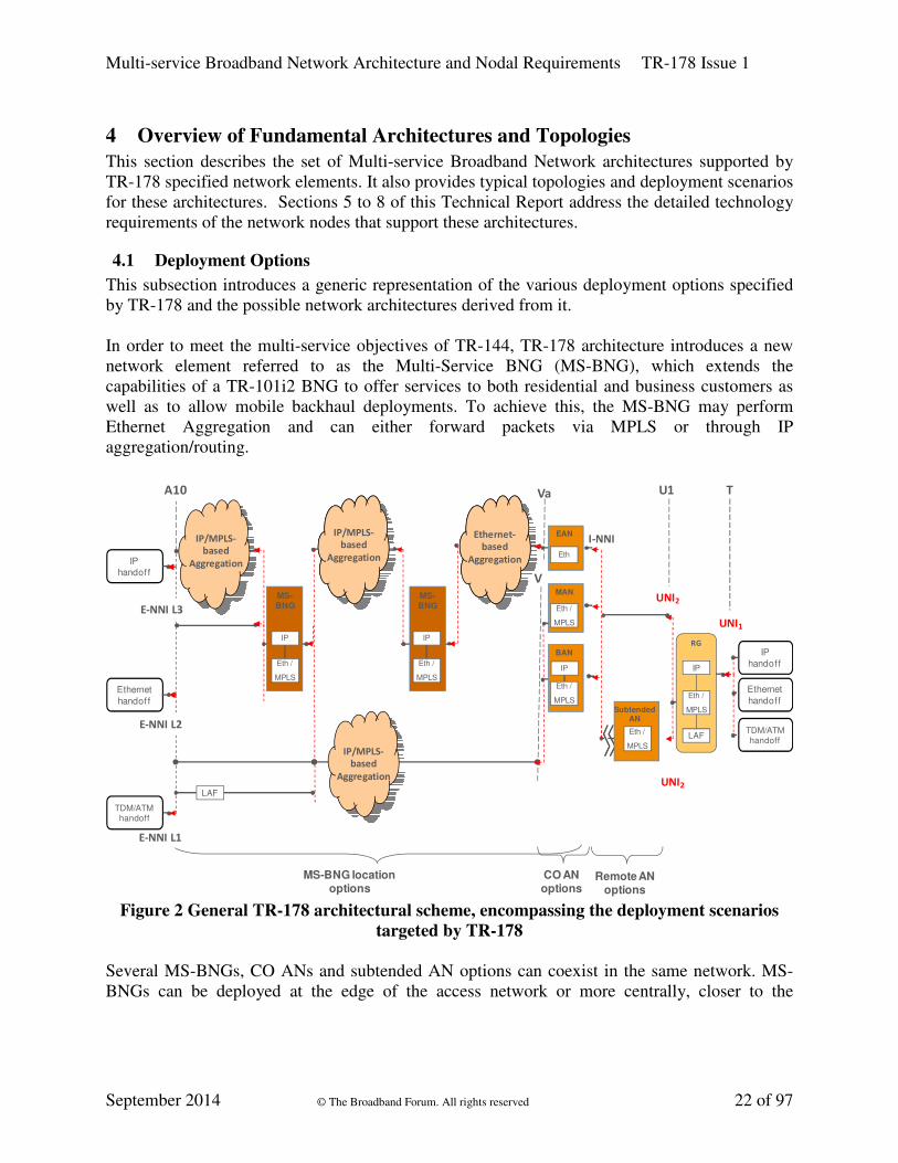
In order to meet the multi-service objectives of TR-144, TR-178 architecture introduces a new
network element referred to as the Multi-Service BNG (MS-BNG), which extends the
capabilities of a TR-101i2 BNG to offer services to both residential and business customers as
well as to allow mobile backhaul deployments. To achieve this, the MS-BNG may perform
Ethernet Aggregation and can either forward packets via MPLS or through IP
aggregation/routing.
Va
I-NNI
IP
handoff
U1 TA10
Ethernet
handoff
MS-BNG
IP
Eth /
MPLS
EAN
MS-BNG location options
Remote AN options
RG
Eth
CO AN options
Eth /
MPLS
LAF
IP
Eth- / MPLS-
based
Aggregation
IP/MPLS-
based
Aggregation
UNI2
UNI1
IP
handoff
Ethernet
handoff
TDM/ATM handoff
SubtendedAN
Eth /
MPLS
MS-BNG
IP
Eth /
MPLS
Eth-/IP-
/MPLS-based
Aggregation
IP/MPLS-
based
Aggregation
Ethernet-
based
Aggregation
LAFUNI2
IP/MPLS-
based
Aggregation
MAN
Eth /
MPLS
BAN
IP
Eth /
MPLS
V
E-NNI L2
E-NNI L3
E-NNI L1
TDM/ATM handoff
Figure 2 General TR-178 architectural scheme, encompassing the deployment scenarios
targeted by TR-178
Several MS-BNGs, CO ANs and subtended AN options can coexist in the same network. MS-
BNGs can be deployed at the edge of the access network or more centrally, closer to the
Multi-service Broadband Network Architecture and Nodal Requirements TR-178 Issue 1
September 2014 © The Broadband Forum. All rights reserved 23 of 97
backbone network1, see Figure 2. For the ANs at the CO level, Ethernet Access Nodes (EAN),
MPLS enabled Access Nodes (MAN) or BNG embedded Access Nodes (BAN) are possible.
Figure 2 shows the possible traffic handoff points from the T reference point all the way to the
A10 reference point. Traffic is handed off across U1 to the ANs via access-specific transmission
media. From the ANs, traffic is handed off across Va onto the Ethernet / MPLS aggregation
network. The Ethernet / MPLS aggregation network must be able to support PtP, Rooted
Multipoint and MPtMP Ethernet connections. From the Ethernet / MPLS aggregation network,
handoff to IP, Ethernet / MPLS and legacy (TDM/ATM, through the Legacy Adaptation
Function -LAF-) networks is possible.
Not all the possible combinations of mixing Ethernet and MPLS functions in the various
elements, and their corresponding hand-offs, are considered. This document focuses on the most
relevant combinations being applied in networks today or in the near future. The specific
architectural schemes are described in the following sections.
4.2 The Ethernet Service Layer
TR-145 sections 4.3 to 4.5 define the Ethernet Service Layer as IVCs between the UNIx and E-
NNI-L2 interfaces, or IVCs between the UNIx and the SI-NNI interface facing the IP
Aggregation network.
TR-178 architectures support the Ethernet Service Layer between the U1 and A10 reference
points, i.e. for Service users and ASP/NSPs, as indicated in TR-145. This implies that TR-178
architectures support all L2 and L3 services, including those offered by the TR-101i2
architecture. TR-101i2 defined two types of service: L2 VPN/TLS Services and IP Services. This
was based upon an Ethernet Aggregation Layer that leveraged clauses 15 & 16 of 802.1Q and
was used to build L2 VPN/TLS services, as well as providing access for IP Services between
Residential Gateways (RGs) and BNGs.
Derivatives of the TR-101i2 architecture, such as defined in TR-156i3 (GPON access)[122] and
TR-167i2 (GPON fed Access Node) [124] are supported in the same way.
All TR-178 architectures must be able to deliver this Ethernet Service Layer independent of any
underlying aggregation and tunnelling technologies. The architecture also needs to support
adaptation of legacy services (TDM) onto the supporting Layer 2 Forwarding (L2F)
functionality. The Ethernet Service Layer will support customer services based on IPv4, as well
as IPv6, as described in TR-177[125] and TR-187[126].
TR-178 also defines additional functionality in the areas of business services, OAM and
manageability, Quality of Service, Multicast and Service Instance tagging, making it deployable
in a multiservice architecture.
1 There are MS-BNGs deployments that might not be specifically addressed in this TR. How to steer traffic to these
nodes is not elaborated in this TR.

Multi-service Broadband Network Architecture and Nodal Requirements TR-178 Issue 1
September 2014 © The Broadband Forum. All rights reserved 24 of 97
4.2.1 L2 NSP wholesale model
One particular capability enabled by the Ethernet Service Layer is the L2 NSP Wholesale Model
This enables next generation access networks to provide connectivity between both residential
and business consumers (end-users) and their respective Network Service Providers (NSPs) in an
open and flexible way. It uses Ethernet transport to allow an access network provider to offer
logically unbundled access. The end user buys services from one or more NSPs who in turn buy
service from the access provider serving the end user. An Infrastructure Virtual Connection (IVC)
is defined at the Ethernet Service Layer (see above) between the UNI (@U/U1) and E-NNI-L2
interfaces (@A10) is defined at the Ethernet layer allowing the NSP maximum freedom in how
they wish to build their service by selecting their interconnect locations. In this way it differs
from wholesale broadband solutions, which operate using PPP and L2TP, or IP, which generally
requires centralised interconnect. Figure 3 below shows a high-level view of the L2 NSP
Wholesale model.
Figure 3 L2 NSP Wholesale Model
The L2 NSP Wholesale service is built out of two components – access and backhaul. A single
Access Network Provider typically serves an end user. If an NSP does not interconnect locally
with the Access Network Provider, the NSP may extend the L2 Wholesale service to another
POP by connecting through a Backhaul Provider Network. The transport technology used within
the Access Provider Network and Backhaul Provider Network could be based on Provider
Ethernet or MPLS, but the handover is Ethernet. In the L2 NSP Wholesale model, the Access
Node is expected to support the functions of an Ethernet Access Node (EAN) as defined in
section 5.4.
The E-NNI at both the Access Network Provider and the Backhaul Provider will support a
provider bridged hand-off that is aligned with the V-reference point specified by TR-101i2. In
the Access Provider Network, an E-NNI for interconnect with NSPs could be supported by the
Access Node. Alternatively, a L2 Aggregation node could be used to provide the E-NNI. The
access network topology used within an Access Provider Network will partly depend on the
access loop technology (e.g. xDSL, xPON, Point-to-Point Ethernet).
The network presentation at the end-user premises is either Ethernet or ‘wires-only’.
• For Ethernet presentation, a L2 NT managed by the Access Network Provider will
terminate the access loop technology and support a VLAN tagged, 802.3 UNI interface at

Multi-service Broadband Network Architecture and Nodal Requirements TR-178 Issue 1
September 2014 © The Broadband Forum. All rights reserved 25 of 97
the U1 reference point. The L2 NT could incorporate a VDSL2 modem or GPON ONT.
Each NSP may supply a CPE that connects to the L2 NT.
• In the wires-only case, the Access Network Provider will provide a passive interface via
an NID in the end-user premises. The end-user CPE will then terminate the access loop
technology. If a second NSP wishes to provide services to the end-user in the wires-only
case either the Access Network Provider will provide a second physical access loop, or
the NSP must connect through the CPE of the primary NSP.
4.2.2 Network Termination at the Customer Premise
The wires-only model has been widely deployed for ADSL access networks, where the ADSL
modem is supplied and installed by the end-user. In some next generation access networks, it
may be desirable to retain this wires-only CPE deployment model. This maximizes the Network
Service Provider’s flexibility to deploy their own CPE without the end-user incurring the
complexity of having both a L2 NT from the Access Network Provider and a Residential
Gateway, however it complicates any sharing of the access loop and may have performance
implications. For access technologies where the network termination is tightly coupled to the
access network (e.g. GPON), deployment of a L2 NT in addition to an NSP CPE may be
required.
Exposing the U1 and the U reference points as external interfaces means that nodal functionality
to support an NNI is required in both the L2 NT and the Access Node. This functionality is
discussed below.
4.2.2.1 Service Identification
At the customer premises, IVCs can be identified either by port or a port and VLAN ID tuple At
the U Reference Point there is usually a single physical interface per end user. In order to support
multiple IVCs at the U- Reference Point, these IVCs must be identified using VLAN tags. Either
S-Tags or C-Tags can be used as a service identifier at this interface.
4.2.2.2 QoS
On ingress to the network the Access Network Provider needs to classify the Class of Service for
each ingress frame. These classes of service can have different frame delivery performance
objectives. Each IVC can have associated bandwidth profiles for each Class of Service. To
support hand-off at U and U1, this class of service mapping and policing of these bandwidth
profiles in the upstream direction will need to be supported by an L2 NT and the Access Node.
The L2 NT may need to schedule traffic into the Access Loop in the upstream direction in a way
that is aware of the Classes of service of the IVCs belonging to multiple NSPs. Similarly, in the
downstream direction, the Access Node may need to manage any contention between NSPs by
scheduling traffic onto the Access Loop.
4.2.2.3 Ethernet OAM
The wires-only model presents the problem of fault demarcation between the customer premises
and the Access Loop. Ethernet OAM between the NSP and the Access Network Operator across
the access loop provides part of a solution for this. This requires support for Ethernet OAM
functions on the Access Loop interface in both the L2 NT and the Access Node.

Multi-service Broadband Network Architecture and Nodal Requirements TR-178 Issue 1
September 2014 © The Broadband Forum. All rights reserved 26 of 97
In order to support an SLA for business end-users, Ethernet performance monitoring needs to be
supported at either the L2-NT or the Access Node.
4.2.3 Ethernet Wholesale QoS Architecture
The TR-101i2 QoS architecture is based on hierarchical scheduling which has 2 key concepts:
• All downstream traffic traverses a single node, typically a BNG, which has complete
knowledge of any potential congestion points between it and the U interface of each
end-user. The BNG can control the traffic so as to manage this congestion. There is
some support for one additional video BNG, but the traffic management between the
two is fairly rudimentary.
• TR-101i2 was primarily intended for mass market residential networks with asymmetric
access (e.g. xDSL) where the majority of the traffic was downstream; there was little
need for QoS control in the upstream.
In contrast, TR-178 does not presume a single service edge, a single BNG (or indeed any BNG),
and although its main focus is still residential, there is the need to support business services as
well. This means QoS management at the Ethernet Wholesale NNI and UNIs, and within any
parts of the network that may be congestion points; further this control is needed in the
upstream as well as the downstream direction. These congestion control capabilities are not only
necessary for wholesale architectures but also for multiple edge architectures.
4.2.4 Ethernet Wholesale Service Classes
This section is an instantiation of a wholesale model following the NICC recommendations.
Other wholesale models are of course possible but they are not described in this section. Hence,
parts of the remainder of this section are slightly edited extracts from some of the NICC
documents [31] to [35]; the source and Copyright of this base material is hereby acknowledged.
The Ethernet Wholesale Service supports 4 QoS Classes (A, B, C, D), A, B and C have some
aspects of the traditional EF, AF and BE Classes. Class C and D are both BE traffic, but Class
D can be constrained to a defined share of the BE traffic under congestion. While they are
intended to support a variety of service types, some typical examples are given in Table 1.
Class Typical Use
A Real time, delay sensitive applications
e.g. voice
B Streaming applications (video)
C Internet data
D Guest or 3rd party Access
Table 1 Examples of service classes supported by Ethernet Wholesale Services
Each of these classes has associated performance objectives that form a per-class Service Level
Specification. These performance objectives are such that Class A has absolute scheduling
priority over Class B, which in turn will have absolute scheduling priority over Classes C and D.
Multi-service Broadband Network Architecture and Nodal Requirements TR-178 Issue 1
September 2014 © The Broadband Forum. All rights reserved 27 of 97
Starvation of the lower priority queues can be avoided by the use of per Class Policers. Example
implementations are described in Annex A of ND1644 [35] .
Classes A and B support only committed bandwidth. The bandwidth available for each of
Classes A and B may need to be restricted by the wholesale services provider to ensure that
performance guarantees can be delivered for lower priority classes and other services.
Classes C and D support both committed and excess bandwidth. The bandwidth profiles at the
UNI and NNI can be configured to be color aware so that the NSP’s drop precedence marking is
respected within these classes. In the case that both classes C and D send excess traffic at the
same time, the wholesale services provider will limit the bandwidth share of Class D. Typical
use cases for Class D would be to support (wireless) guest access at the end-user premises, or to
limit the bandwidth of a background application such as push video.
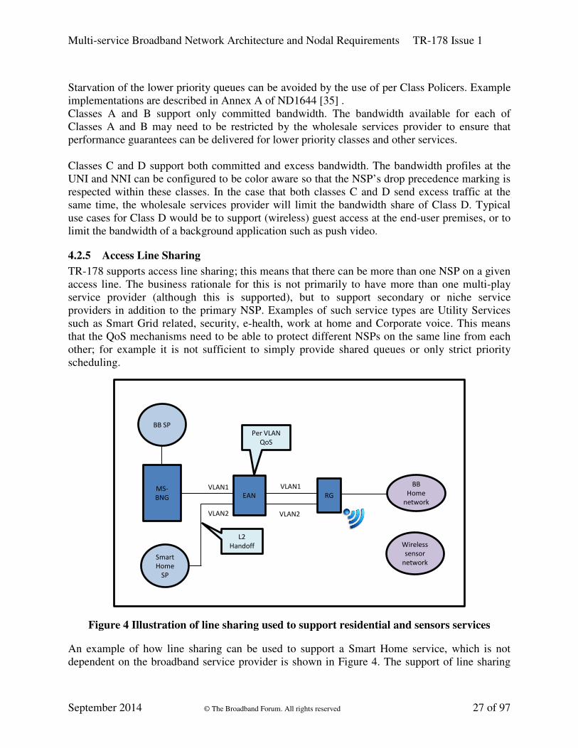
4.2.5 Access Line Sharing
TR-178 supports access line sharing; this means that there can be more than one NSP on a given
access line. The business rationale for this is not primarily to have more than one multi-play
service provider (although this is supported), but to support secondary or niche service
providers in addition to the primary NSP. Examples of such service types are Utility Services
such as Smart Grid related, security, e-health, work at home and Corporate voice. This means
that the QoS mechanisms need to be able to protect different NSPs on the same line from each
other; for example it is not sufficient to simply provide shared queues or only strict priority
scheduling.
RGEANMS-
BNG
Wireless
sensor
network
Per VLAN
QoS
VLAN1
VLAN2
BB SP
Smart
Home
SP
L2
Handoff
VLAN1
VLAN2
BB
Home
network
Figure 4 Illustration of line sharing used to support residential and sensors services
An example of how line sharing can be used to support a Smart Home service, which is not
dependent on the broadband service provider is shown in Figure 4. The support of line sharing

Multi-service Broadband Network Architecture and Nodal Requirements TR-178 Issue 1
September 2014 © The Broadband Forum. All rights reserved 28 of 97
places requirements on the number and type of queues in the Access Node, the ability to map
traffic to queues on the basis of VID and .1Q bits, and per queue policing (see Section 5.4).
4.2.6 Ethernet Wholesale Port Types
Ethernet Wholesale ALA supports three (user) port types:
• A port based UNI.
• An S-tagged UNI.
• A customer edge port based UNI
The S-Tagged UNI requires the NSP to identify the connection of a frame using either an S-
VLAN tag or the default S-VLAN on the port.
A customer edge port based UNI offers the same capability but in this case any C-VLAN tags
used at the UNI are tunneled over a point-to-point connection. This means that to use a VLAN-
tagged presentation at the UNI the NSP will need to send three VLAN tags at the NNI; where the
two outer VLAN tags are defined by the ALA User Connection (AUC) endpoint map ND1644
[35] at the NNI and the inner-most VLAN tag needs to match the VLAN tag being used by the
NSP at the UNI. This innermost VLAN tag is not significant to the wholesale service provider at
the NNI and is carried transparently over it.
4.2.6.1 Frame handling at a port based UNI
At a port based UNI the UNI identifier identifies the connection. All ALA service frames
received on the UNI that have a TPID of 0x8100 shall be accepted regardless of any VLAN
tagging and provider tagging applied as if they were untagged frames. All ALA service frames
received on the UNI that have a TPID of 0x88A8 should be accepted regardless of any VLAN
tagging and similarly treated. All traffic is put on the same IVC, regardless of the C-VLAN or S-
VLANs that are present in the customer traffic. In the downstream direction (towards the end
user) any VLAN tags used by the NSP to identify the connection will be stripped before the
frame is passed over the UNI. Note that this mode only supports a single Class of Service
ND1030 [31].
4.2.6.2 Frame handling at an S-tagged UNI
At an S-tagged UNI the AN uses the connection end point map to map the S-VID of a received
frame to an (IVC) connection. The UNI connection end point map will therefore contain a list of
S-VID to connection mappings. Traffic arriving over the connection will be relayed over the
UNI with the appropriate S-tag. An S-VID will map to at most one IVC and an IVC will map to
only one S-VID.
At each S-tagged UNI it is possible to define a default VLAN to which any untagged or priority
tagged frames are mapped. This default VLAN can be mapped to a connection (as for any other
S-tagged VLAN) by the end point map. If no default VLAN is defined for the UNI then
untagged and priority tagged frames will be dropped since they do not match a defined S-VID.
4.2.6.3 Frame handling at an customer edge port UNI
At a customer edge port UNI, one C-Tag value is used to identify the multicast connection. This
value needs to be defined by the wholesale service provider as part of their product description.

Multi-service Broadband Network Architecture and Nodal Requirements TR-178 Issue 1
September 2014 © The Broadband Forum. All rights reserved 29 of 97
All other frames, untagged, priority tagged or tagged with a value other than the multicast tag,
are mapped to the point to point connection. The priority within the connection for frames
entering the network at the UNI is mapped from the priority bits of C-tags received; see section
7.4.2.3 in ND1644 [35] for details.
4.2.7 Multicast wholesale services
A separate (point to multipoint) VLAN is always used for multicast between the Ethernet
wholesale service provider and NSP; this model is supported in TR-101i2 and there are only a
few new requirements needed to support this connectivity in a wholesale context (see Section
5.4.6).
4.2.8 Ethernet OAM
TR-144 outlines the need for an architecture that supports both residential and business services
for retail and wholesale business models. An important aspect of such an architecture is the
ability to use common access infrastructure, but there is a need to separate these disparate
services and businesses by leveraging multiple back-end elements. These elements can be
service-specific and can be managed by disparate organizational entities. While additional
complexity is introduced in the access network architecture in order to cater for multiple service
edges, the alternative – having all services in a single element and therefore a single edge –
quickly brings up the typical objections of specifying a “god box” that solves every problem.
The network OAM facilities need to be deployed in a similar way: using a common approach in
the access network across services and providers, but able to support multiple backend or far-end
service edges. Moreover, the OAM facilities need to be flexible as to the amount of overhead
and signaling they use in order to cater for the disparate needs of a wide variety of consumer and
business network services.
In the work done in TR-145, physical topology requirements have been brought forward that
show wholesale interfaces for access both in central locations, as well as distributed locations
(e.g. from an Access Node).
Ethernet OAM supports multiple maintenance levels that were leveraged in both TR-101i2 and
later architectures in order to support the needs of users and various service providers to manage
network portions, partitions, and end-to-end. TR-178 builds on this capability to support the new
multi-service, multi-edge requirements in TR-144.
Section 7 of TR-101i2 outlines the basic OAM model in terms of how the maintenance entity
levels are structured. It also provides for maintenance levels that acknowledge both retail and
wholesale models. The intention of the TR-178 architecture is to maintain this model as much as
possible for MS-BNGs in order to offer a consistent toolset and procedures independent of the
MS-BNG location in the network.
The primary change is that the MS-BNG needs to be able to originate and terminate CFM
(clauses 18 to 22 of 802.1Q [3]) / Y.1731 [132] PDUs across the Ethernet PW RFC 4448 [69]
used to provide the virtual port extension from a centrally deployed MS-BNG to an MS-BNG
deployed at the edge. This places additional requirements on the centrally deployed MS-BNG as

Multi-service Broadband Network Architecture and Nodal Requirements TR-178 Issue 1
September 2014 © The Broadband Forum. All rights reserved 30 of 97
well as the need to provide MIP or MEP functionality for certain maintenance entity levels that
originate from the MS-BNG deployed at the edge.
TR-101i2 has two OAM models, one for retail and one for wholesale. This section updates that
model depending on whether the wholesale E-NNI is between the centrally deployed MS-BNG
and the access network or whether the E-NNI is between the centrally deployed MS-BNG and
the MS-BNG deployed at the edge.
The basic OAM architectural principles of TR-101i2 are preserved in the design of the
maintenance levels. The guiding principle is exposure of appropriate information to each of the
managing entities, so for example, the inter-carrier level does not have MIPs in transit nodes, but
does have MIPs straddling demarcation boundaries.
The primary change from TR-101i2 is the edge deployed MS-BNG is a bridging point for
services hosted at a centrally deployed MS-BNG. The maintenance level the customer has
access to is limited to MIP/MEP processing at service end points or the termination of the access
uplink. The generalized MIP/MEP design limits visibility of the different network domains to the
relevant actors.
The following diagrams illustrate representative cases of single provider and multi provider
scenarios. When considering the requirements of an actual deployment, it should be noted that
nodes implementing MIP functionality may not exist in some scenarios, or be collapsed into a
node which also implements a MEP (e.g. in the scenario where an AN is a BAN). However, the
removal or collapsing of any intermediate node does not alter the overall model.
Figure 5 depicts the retail OAM architecture for residential access if extended to a centrally
deployed MS-BNG in a hierarchy.
Figure 5 Retail OAM model for L3 Access in a MS-BNG hierarchy
MIP
MEP
Customer
RGAccess
Node
Aggregation
NodeMS-BNG
(e2e) RG to MS-BNG ME (Customer)
Access Port to MS-BNG ME (Inter-Carrier)
Access Node to MS-BNG ME (Intra-Carrier)
I-NNI
Access Link ME
MS-BNG
I-NNII-NNI

Multi-service Broadband Network Architecture and Nodal Requirements TR-178 Issue 1
September 2014 © The Broadband Forum. All rights reserved 31 of 97
Figure 6 illustrates the Ethernet services variation of this model as the edge deployed MS-BNG
implements MIP functionality at the carrier level. In this scenario both the MS-BNGs in the
hierarchy are bridging points with respect to the service offered.
MIP
MEP
Customer
RGAccess
Node
Aggregation
NodeMS-BNG
(e2e) RG to MS-BNG ME (Customer)
Access Port to MS-BNG ME (Inter Carrier)
Access Node to MS-BNG ME (Intra-Carrier)
I-NNI
Access Link ME
MS-BNG
I-NNII-NNI
Figure 6 Retail OAM Model for Ethernet Services for a MS-BNG hierarchy
Figure 7 depicts the OAM architecture for wholesale L3 access services where the E-NNI is
between the edge deployed MS-BNG and the Ethernet access network.
MIP
MEP
Customer
RGAccess
NodeAggregation
NodeMS-BNG
(e2e) RG to MS-BNG ME (Customer)
Access Port to MS-BNG ME (Inter-Carrier)
Access Node to MS-BNG ME (Intra-Carrier)
E-NNI
Access Link ME
MS-BNG
I-NNII-NNI
MS-BNG to MS-BNG ME (Intra-Carrier)
NNI ME
Figure 7 Wholesale OAM model for L3 access in a hierarchy with the E-NNI at the
hierarchy ingress
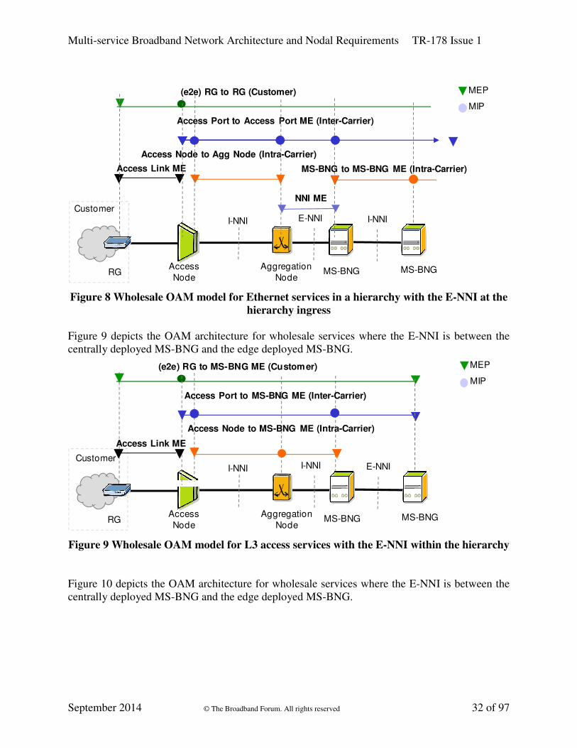
Figure 8 illustrates the OAM architecture for Ethernet services where the E-NNI is between the
centrally deployed MS-BNG and the Ethernet access network.
Multi-service Broadband Network Architecture and Nodal Requirements TR-178 Issue 1
September 2014 © The Broadband Forum. All rights reserved 32 of 97
MIP
MEP
Customer
RGAccess
Node
Aggregation
NodeMS-BNG
(e2e) RG to RG (Customer)
Access Port to Access Port ME (Inter-Carrier)
Access Node to Agg Node (Intra-Carrier)
E-NNI
Access Link ME
MS-BNG
I-NNII-NNI
MS-BNG to MS-BNG ME (Intra-Carrier)
NNI ME
Figure 8 Wholesale OAM model for Ethernet services in a hierarchy with the E-NNI at the
hierarchy ingress
Figure 9 depicts the OAM architecture for wholesale services where the E-NNI is between the
centrally deployed MS-BNG and the edge deployed MS-BNG.
MIP
MEP
Customer
RGAccess
Node
Aggregation
NodeMS-BNG
(e2e) RG to MS-BNG ME (Customer)
Access Port to MS-BNG ME (Inter-Carrier)
Access Node to MS-BNG ME (Intra-Carrier)
I-NNI
Access Link ME
MS-BNG
E-NNII-NNI
Figure 9 Wholesale OAM model for L3 access services with the E-NNI within the hierarchy
Figure 10 depicts the OAM architecture for wholesale services where the E-NNI is between the
centrally deployed MS-BNG and the edge deployed MS-BNG.

Multi-service Broadband Network Architecture and Nodal Requirements TR-178 Issue 1
September 2014 © The Broadband Forum. All rights reserved 33 of 97
MIP
MEP
Customer
RGAccess
Node
Aggregation
NodeMS-BNG
(e2e) RG to RG (Customer)
Access Port to Access Port ME (Inter-Carrier)
Access Node to MS-BNG ME (Intra-Carrier)
I-NNI
Access Link ME
MS-BNG
E-NNII-NNI
Figure 10 Wholesale OAM model for Ethernet services with the E-NNI within the
hierarchy
It should be noted that no new requirements are placed on the Residential Gateway (RG), AN or
Aggregation nodes. These nodes support the existing requirements for OAM developed
generically in TR-101i2, and for PON ANs in TR-156i3, TR-157 [123], and TR-200 [127].
4.2.8.1 Ethernet wholesale OAM and the TR-101i2 model
NICC defines an Ethernet OAM architecture that is very similar to the TR-101i2 model but with
some subtle differences. The mapping of Ethernet OAM to the NICC Ethernet wholesale
architecture is shown in Figure 11 below [31]:
Figure 11 Ethernet OAM Architecture for ALA using the conventions from IEEE 802.1Q
Figure 11 shows the following MEGs:
A1, A2
CPE NTU
A3, A4
UNI MEG NNI MEG
Connection MEG
NSP MEG
Untagged
Tagged Extended-connection MEG

Multi-service Broadband Network Architecture and Nodal Requirements TR-178 Issue 1
September 2014 © The Broadband Forum. All rights reserved 34 of 97
4.2.8.1.1 NSP MEG
The Ethernet wholesale service provider configures the NSP MEG on the VLAN that supports
the connection. It supports MIPs that allow the NSP to perform LinkTrace and loopback
operations to the UNI and NNI for each connection. This MEG is roughly equivalent to the EVC
ME in the MEF architecture [30] and the Customer ME in the TR-101i2 architecture. It has
additional MIPS at the demarcation boundaries that do not exist in the TR-101i2 OAM
architecture or the MEF architecture. TR-101i2 does have an additional “down” MEP in the AN
in this ME.
4.2.8.1.2 Extended connection MEG
The Extended-connection MEG allows an NSP to monitor the Frame Delay and Frame Loss
performance of a connection without deploying CPE. It supports a MEP at the Ethernet
wholesale service UNI that supports loopback and LinkTrace and generation of Y.1731 [132]
LMR and DMR Messages in response to a Y.1731 LMM or DMM message from a remote MEP.
This allows support for Single Ended Frame Loss measurement and Two-Way Frame Delay
Measurement. This again is roughly equivalent to the Inter-Carrier ME in the TR-101i2
architecture and the Service Provider ME in the MEF architecture.
4.2.8.1.3 Connection MEG
The Ethernet wholesale service provider can configure the NSP MEG congruent with the VLAN
that supports the connection. It supports MEPs that allow the Ethernet wholesale service
provider to run continuity check, LinkTrace and loopback operations between the UNI and NNI
for each connection. Support of this MEG by the Ethernet wholesale service provider allows the
Ethernet wholesale service provider to report the state of the connection to the NSP using ETH-
AIS. This MEG is roughly equivalent to the Operator ME in the MEF architecture, and the
Carrier ME in the Broadband Forum TR-101i2 Architecture.
The connection MEG exists entirely within the domain of the Ethernet wholesale service
provider. The operation of this MEG is therefore a matter for the Ethernet wholesale service
provider and does not need to be specified as part of the Ethernet wholesale service. The only
related requirement arising from the Ethernet wholesale service definition is that a MEG-level is
reserved for the use of the Ethernet wholesale service provider.
4.2.8.1.4 UNI MEG
The UNI MEG monitors the UNI interface. It can support Continuity Check, Loopback and
LinkTrace.
This MEG is equivalent to the Access Link ME in TR-101i2 and the MEF UNI ME.
4.2.8.1.5 NNI MEG
The NNI MEG monitors the NNI interface. It can support Continuity Check, Loopback and
LinkTrace.
This MEG is equivalent to the MEF NNI MEG.

Multi-service Broadband Network Architecture and Nodal Requirements TR-178 Issue 1
September 2014 © The Broadband Forum. All rights reserved 35 of 97
4.2.8.2 VLAN tagging of connection and NSP MEGs
The VLAN tagging of the connection determines the VLAN tagging of Ethernet OAM frames in
the connection MEG. Extended connection MEG and the NSP MEG. If the Ethernet wholesale
service NNI is single tagged, then the connection between the NNI and the UNI can be modeled
as an S-VLAN bridge. This means that implementation of the MEP and MIP functions at the
NNI should be supported by a standard IEEE provider bridge.
4.2.8.3 Performance Management
Ethernet OAM supports frame-loss measurement (ETH-LM), and frame delay measurement
(ETH-DM). These measurements can be used by the Ethernet wholesale service provider and the
NSP to generate values for the frame-loss, frame delay and frame delay variation described in the
Service Level Agreement.
4.3 The reach of MPLS
Some operators consider it desirable to increase the scope of the MPLS domain in their network
to either replace or diminish the scope of the access network and to leverage MPLS features such
as traffic engineering and resiliency.
The approaches generally fall into two classes. The first is the use of MPLS for backhaul of
customer traffic to service edges; the second is to push the service edge closer to the customer. In
the first case a lighter weight form of MPLS may be employed as the “MPLS edge” that does not
implement the full set of services and subscriber management that can be supported by an MPLS
network and is associated with a service edge. In the latter case the “MPLS edge” implements
the totality of the MPLS architecture and subscriber management features normally associated
with a MS-BNG.
In both cases, the extreme is that the MPLS edge is co-located with the Access Node, which
gives rise to two classes of nodes not previously considered in BBF architectures. These are:
• The MPLS enabled Access Node (MAN) which is a class of Access Node that
implements the minimum set of MPLS functionality needed for it to serve in a backhaul
role.
• The BNG embedded Access Node (BAN) which is an Access Node that implements the
set of features normally associated with the combination of an Access node, a subset of
MS-BNG features and an MPLS PE.
It also becomes possible to consider a scenario in which MPLS in a backhaul role is not extended
all the way to the AN, which gives rise to the MPLS enabled aggregation node.
All of these node types as well as strategies for reducing complexity where necessary are
discussed in the following sections and in nodal requirements.
4.3.1 Seamless MPLS
Seamless MPLS, as represented in Figure 12, is an architecture enabling the deployment of
MPLS enabled Access Nodes while minimizing the complexity of the additional Access Node

Multi-service Broadband Network Architecture and Nodal Requirements TR-178 Issue 1
September 2014 © The Broadband Forum. All rights reserved 36 of 97
functions. Seamless MPLS is an architectural combination and deployment of different
mechanisms leading to simplified control and data plane requirements on Access Nodes. It
enables the setup of LSPs and PW over multiple administrative areas, building a single MPLS
domain.
Figure 12 Seamless MPLS Architecture
From an organizational and operational point of view it may be desired to define the boundaries
of such domains along the pre-existing boundaries between aggregation networks and the core
network. This means the MPLS LSP starts in one access domain, goes over the core network and
terminates in a different access domain. To ensure a minimal control plane on Access Nodes,
LDP-extension for inter-area LSPs and LDP downstream-on-demand are used. In this mode, the
Access Node (AN) explicitly asks the Aggregation Node (AGN) for a label binding for a
particular FEC when needed for upstream traffic, and the AGN asks the AN for label binding for
downstream traffic.
4.3.2 Access Node Options with MPLS capabilities
The Access Node with MPLS capabilities can be deployed in different scenarios, as shown in
Figure 13, influenced by access technologies, capacity and position of the Access Node, targeted
scalability of MPLS-based services as well as the operator’s overall network evolution plan. The
set of TR-178 services are supported in all deployment options via MPLS PWs.
Figure 13 Deployment Options with MPLS enabled Access Node
AGN
AN
ABR ABR AGN
ANBackbone Routing Area
Aggregation
Routing Area
Static
Seamless MPLS
Static
Aggregation
Routing Area
Dynamic Infrastructure
AGN
AN
ABR ABR AGN
ANBackbone Routing Area
Aggregation
Routing Area
Static
Seamless MPLS
Static
Aggregation
Routing Area
Dynamic Infrastructure

Multi-service Broadband Network Architecture and Nodal Requirements TR-178 Issue 1
September 2014 © The Broadband Forum. All rights reserved 37 of 97
This sub-section only describes those portions of the network that contain Access Nodes with
MPLS capabilities. Overall MPLS network architectures are specified in TR-221 and TR-224.
The deployment options in this section are intended to assist the understanding of the scenarios
and requirements of MPLS enabled Access Nodes.
Operators may want MPLS capabilities in Access Nodes but these can increase the complexity
and cost of the nodes. Simple, lightweight solutions for small nodes are preferred. Seamless
MPLS is one solution, which does not place a heavy burden on Access Nodes.
In the deployment scenarios outlined in this document, a full-featured MPLS Access Node
always has a BNG function embedded and it is called a BNG embedded Access Node (BAN). In
contrast, an MPLS enabled Access Node (MAN) just has the simple MPLS adaptation functions.
A full-featured MPLS Access Node is usually CO-based and has a large subscriber capacity, so
that it needs to be powerful and more complex. An Access Node with simpler MPLS capability
may be preferred. This can be achieved by simplifying the MPLS control plane, e.g. by removing
dynamic routing protocols. In this case the Access Node can be configured with default routing
entries when there is only one link between the Access Node and the aggregation network.
MPLS labels and PW labels on the Access Node could be statically configured via the
management plane, instead of by dynamic label distribution protocols. Though such
simplification reduces complexity on the Access Nodes, it loses the flexibility of an end-to-end
dynamic routing and control plane, however the other benefits of end-to-end MPLS are retained.
The Access Node can take different roles according to its MPLS capabilities as described in the
following sections.
4.3.2.1 MPLS enabled Access Node (MAN)
The MPLS enabled Access Node acts as a PE node for MPLS and MPLS PWs not requiring
dynamic routing protocols. This scenario is a common case for residential and L3VPN services.
It may also apply to mobile backhaul or ATM DSLAM backhaul when the AN has ATM or
T1/E1 interfaces.
4.3.2.2 BNG embedded Access Node (BAN)
The BAN can perform one or more of the following roles:
i. The BAN acts as a P node for MPLS and MPLS PW, while the CPE or ONU acts as a T-PE.
Only single segment PWs are visible to the AN acting as a P node. This scenario applies to
small scale PW networks. PON-fed ANs or subtended ANs can also be a PE for MPLS and
E2E MPLS PWs. This scenario applies to residential services for FTTB/C, and to mobile
backhaul if the Access Node has ATM or T1/E1 interfaces.
ii. The BAN acts as a switching PE (S-PE) for MPLS and MPLS PW. The Access Node splits
PWs into multiple segments and performs PW switching between the user and network sides.
As PWs are split by the Access Node, a large network is divided into several smaller
domains and the scalability of PWs is thereby extended. This scenario may be applied to
large scale PW network. A PON-fed AN or subtended AN can be a T-PE for E2E MPLS PW.
iii. The BAN acts as a PE node and provides L2 VPN services, supporting an overlay model
carrying other services from CPE or ONU to their peer PEs.
Multi-service Broadband Network Architecture and Nodal Requirements TR-178 Issue 1
September 2014 © The Broadband Forum. All rights reserved 38 of 97
In addition to any of these, the BAN can act as an IP Edge for residential and business services.
4.4 TR-178 architectural options
TR-101i2 specified Ethernet connectivity between Broadband Network Gateways and Access
Nodes, without providing details on how to deliver such connectivity through an Aggregation
Network. TR-224 introduced MPLS in Carrier Ethernet Networks, and TR-221 introduced
MPLS in Mobile Backhaul Networks. MPLS can be used in multiple ways in Multi-Service
Broadband Networks, depending on a number of operational factors such as the scale of the
network, the location of the service edges in the network, the degree of automation and the
homogeneity desired in managing the network, etc.
This section describes MSBN architectural variants using MPLS to different extents – either
confined to the Aggregation Network, or involving Broadband Network Gateways, Access
Nodes, or further nodes such as a Cell Site Gateway (CSG) or a Mobile Aggregation Site
Gateway (MASG). Each architectural variant is described by a figure representing the
distribution of functions into network nodes at a high level. The use of such MPLS constructs
does not preclude the use of regular Ethernet aggregation as described in TR-101i2, which
remains fully valid in a TR-178 context.
Section 4.4.1 describes the three primary architectural variants leveraging TR-224 MPLS
principles to provide consumer and business services through fixed broadband access.
Section 4.4.2 then introduces mobile backhaul concepts as defined by TR-221 and corresponding
nodes (e.g. CSG, MASG), and illustrates how such concepts and nodes fit in a TR-178
architecture, using either an overlay model or a more integrated model.
4.4.1 Fixed Broadband Access
This section illustrates the three primary architectural variants for fixed broadband access. This is
not intended as a complete and exhaustive list, as sub-variants can be deployed by mixing and
matching some of those constructs, but these should be representative of the primary
architectural possibilities enabled by TR-178.
The three primary scenarios for fixed broadband access are:
1) Standalone, centrally deployed MS-BNG in which an MPLS network is used to backhaul
subscriber traffic from the access facilitating flexibility in the selection of MS-BNG
location.
2) Standalone, edge deployed MS-BNG in which the placement of the edge BNG is
typically dictated by the depth of the Ethernet access network.
3) Hierarchical deployment of MS-BNGs in which some subscribers of a subtending AN
have their service edge hosted on the edge deployed MS-BNG, and others have their
service edge hosted at a centrally deployed MS-BNG. This architecture may exist for
business reasons within a single operator, flexibility in service placement within a single
operator, or to facilitate multi-operator wholesaling.

Multi-service Broadband Network Architecture and Nodal Requirements TR-178 Issue 1
September 2014 © The Broadband Forum. All rights reserved 39 of 97
4.4.1.1 Standalone Centrally deployed MS-BNG
Figure 14 and Figure 15 illustrate the distribution of functional modules and nodes required to
introduce MPLS in a TR-224 aggregation network, for a centrally deployed, standalone MS-
BNG architecture. Both consumer services and business services (as required by TR-144) can be
supported, using the appropriate type of Customer Premise Gateway served by a Multi-Service
BNG.
In this figure, by default, the MS-BNG does not act as an aggregation-facing MPLS PE node,
hence staying close to a TR-101i2 architecture. The MS-BNG can provide MPLS-based services
though (e.g. E-Line or L2/L3 VPN business service), hence acting as an MPLS PE on the core-
facing side.
MPLS P/PE
AN
Access-specific
Transmission
(DSL or Fiber)
B-NT(consumer)MPLS P
MPLS PE
Ethernet
handoff
MPLS
IP
UT
Vc
B-NT(business)
Ethernet
handoffETH
IP
handoff
ETH Ethernet
handoff
IP
handoff
IP
ETHETH
MPLS MPLS
IP
handoffIP
MS-BNG
A10
V/Va
ETH
ETH
IP/
MP
LS
Co
re N
etw
ork
MPLS
Figure 14 Ethernet Access Node, centrally deployed standalone MS-BNG
Alternatively (as represented by the red dotted line), the MS-BNG could be combined with full
aggregation-facing MPLS functionality (including the Ethernet A10 hand-off), while the Access
Node would remain Ethernet-centric.
Figure 15 illustrates the distribution of functional modules and nodes required to introduce
MPLS in the MS-BNG, aggregation network and ANs for a centrally deployed BNG
architecture. The MPLS feature set on the Access Node is assumed to be lightweight, not
requiring any dynamic routing protocol, according to the principles of seamless-MPLS [37].
Note that end-to-end Ethernet business services (e.g. E-Line, E-LAN) can be supported by
extending the scope of MPLS end to end, i.e. from one Access Node to another through the
entire Multi-Service Broadband Network. Another approach is to use MPLS in the aggregation
network as a ‘transport’ layer, while the MS-BNG would provide MPLS-based services.

Multi-service Broadband Network Architecture and Nodal Requirements TR-178 Issue 1
September 2014 © The Broadband Forum. All rights reserved 40 of 97
AN/
MPLS PE
MPLS P ETH
MPLS MPLS
IP
handoff
MS-BNG/
MPLS PE
V
Access-specific
Transmission
(DSL or Fiber)
B-NT(consumer)
IP
UT
Vc
B-NT(business)
Ethernet
handoffETH
IP
handoff
ETH Ethernet
handoff
IP
handoff
IPMPLS P/PE
Ethernet
handoffETH
MPLS
MPLSETH
A10
IP
IP/
MP
LS
Co
re N
etw
ork
Figure 15 MPLS Access Node, centrally deployed standalone MS-BNG
Alternatively (as represented by the red dotted line), the MS-BNG could be combined with full
aggregation-facing MPLS functionality (including the Ethernet A10 hand-off).
4.4.1.2 Standalone Edge deployed MS-BNG
Figure 16 and Figure 17 illustrate the distribution of functional modules and nodes required to
introduce MPLS in the broadband aggregation network for an edge deployed, standalone MS-
BNG architecture. The MS-BNG is deployed close to Ethernet Access Nodes (e.g. in a Central
Office), or is embedded in the AN providing aggregation and MPLS PE functions in addition to
its usual subscriber management role.
MPLS P/PE
AN
MS-BNG/
MPLS PE
MPLS
IP
ETHMPLS P
MPLS
V/Va
ETH
Access-specific
Transmission
(DSL or Fiber)
B-NT(consumer)
IP
UT
Vc
B-NT(business)
Ethernet
handoffETH
IP
handoff
ETH Ethernet
handoff
IP
handoff
IP
Ethernet
handoff
A10
MPLS
ETH
IP/
MP
LS
Co
re N
etw
ork
IP
handoff
Figure 16 Ethernet Access Node, edge deployed standalone MS-BNG

Multi-service Broadband Network Architecture and Nodal Requirements TR-178 Issue 1
September 2014 © The Broadband Forum. All rights reserved 41 of 97
MPLS P/PE
AN/
MPLS PE/BNG
V
Access-specific
Transmission
(DSL or Fiber)
B-NT(consumer)
IP
UT
Vc
B-NT(business)
Ethernet
handoffETH
IP
handoff
ETH Ethernet
handoff
IP
handoff
IP
ETH
MPLS
IP
MPLS P
MPLS
IP
handoff
Ethernet
handoff
A10
MPLS
ETH
IP/
MP
LS
Co
re N
etw
ork
Figure 17 Standalone BNG embedded Access Node
4.4.1.3 Hierarchical MS-BNG deployment
Figure 18 & Figure 19 illustrate the distribution of functional modules and nodes required to
introduce MPLS in the broadband aggregation network for a hierarchical BNG architecture. The
edge MS-BNG is deployed close to Ethernet Access Nodes (e.g. in a Central Office), or
incorporated into BNG embedded Access Nodes providing aggregation and MPLS PE functions
in addition to their usual subscriber management role. In a hierarchical construct, some
subscribers will be served by the edge deployed MS-BNG, and others by the centrally deployed
MS-BNG.
MPLS P/PE
AN
MS-BNG/
MPLS PE
MPLS
IP
ETH
MPLS P
MPLS
V/Va
ETH
Access-specific
Transmission
(DSL or Fiber)
B-NT(consumer)
IP
UT
Vc
B-NT(business)
Ethernet
handoffETH
IP
handoff
ETH Ethernet
handoff
IP
handoff
IP
Ethernet
handoff
A10
MS-BNG/
MPLS PE
MPLS
MPLSETH
IP
ETH
IP/
MP
LS
Co
re N
etw
ork
IP
handoff
Figure 18 Ethernet Access Node deployed with hierarchical MS-BNGs
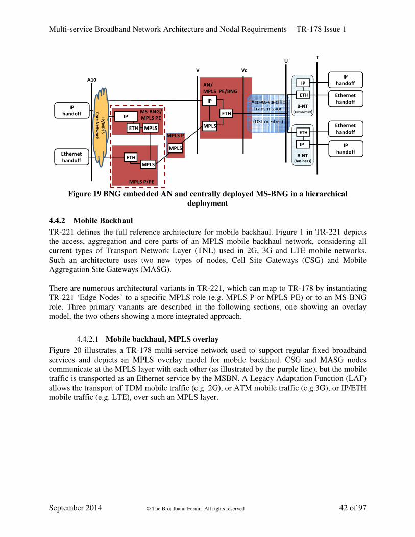
Multi-service Broadband Network Architecture and Nodal Requirements TR-178 Issue 1
September 2014 © The Broadband Forum. All rights reserved 42 of 97
MPLS P/PE
AN/
MPLS PE/BNG
V
Access-specific
Transmission
(DSL or Fiber)
B-NT(consumer)
IP
UT
Vc
B-NT(business)
Ethernet
handoffETH
IP
handoff
ETH Ethernet
handoff
IP
handoff
IP
ETH
MPLS
IP
MPLS P
MPLS
IP
handoff
Ethernet
handoff
A10
MS-BNG/
MPLS PE
MPLS
MPLSETH
IP
ETH
IP/
MP
LS
Co
re N
etw
ork
Figure 19 BNG embedded AN and centrally deployed MS-BNG in a hierarchical
deployment
4.4.2 Mobile Backhaul
TR-221 defines the full reference architecture for mobile backhaul. Figure 1 in TR-221 depicts
the access, aggregation and core parts of an MPLS mobile backhaul network, considering all
current types of Transport Network Layer (TNL) used in 2G, 3G and LTE mobile networks.
Such an architecture uses two new types of nodes, Cell Site Gateways (CSG) and Mobile
Aggregation Site Gateways (MASG).
There are numerous architectural variants in TR-221, which can map to TR-178 by instantiating
TR-221 ‘Edge Nodes’ to a specific MPLS role (e.g. MPLS P or MPLS PE) or to an MS-BNG
role. Three primary variants are described in the following sections, one showing an overlay
model, the two others showing a more integrated approach.
4.4.2.1 Mobile backhaul, MPLS overlay
Figure 20 illustrates a TR-178 multi-service network used to support regular fixed broadband
services and depicts an MPLS overlay model for mobile backhaul. CSG and MASG nodes
communicate at the MPLS layer with each other (as illustrated by the purple line), but the mobile
traffic is transported as an Ethernet service by the MSBN. A Legacy Adaptation Function (LAF)
allows the transport of TDM mobile traffic (e.g. 2G), or ATM mobile traffic (e.g.3G), or IP/ETH
mobile traffic (e.g. LTE), over such an MPLS layer.

Multi-service Broadband Network Architecture and Nodal Requirements TR-178 Issue 1
September 2014 © The Broadband Forum. All rights reserved 43 of 97
Figure 20 Mobile backhaul, MPLS overlay
4.4.2.2 Mobile backhaul, MPLS integrated (in Aggregation)
Figure 21 illustrates a more integrated mobile backhaul approach, contained within the MSBN,
combining MASG functionality with an MPLS PE (aggregation) node before the A10 hand-off.
The MPLS traffic originated by the CSG is switched by the MPLS (aggregation) nodes to the
MASG (as illustrated by the purple line), while the Ethernet traffic originated by the (fixed) B-
NTs is conveyed by MPLS to the MS-BNG.
MPLS
P/PE
MPLS P
AN
Vc
MPLS PE/
MASG
B-NT(consumer)
Ethernet
handoff
IP
T
B-NT(business)
Ethernet
handoffETH
IP
handoff
ETH Ethernet
handoff
IP
handoff
IP
CSG(cell site)
LAFTDM or ATM
or IP handoff
Ethernet
handoff
TDM or ATM
or IP handoff
U
V/Va
IP
handoffIP
ETH
MS-BNG
ETH
Access-specific
Transmission
(DSL or Fiber)
A10
MPLS
LAF
MPLS MPLS
MPLS
ETH
ETH ETH
IP/M
PLS
Co
re N
etw
ork
Figure 21 Mobile backhaul, MPLS integrated (Aggregation)

Multi-service Broadband Network Architecture and Nodal Requirements TR-178 Issue 1
September 2014 © The Broadband Forum. All rights reserved 44 of 97
4.4.2.3 Mobile backhaul, MPLS integrated (Access)
Figure 22 illustrates another integrated mobile backhaul approach, contained within the MSBN,
combining MPLS S-PE functionality with the Access Node and combining MASG and MPLS T-
PE functionality with an MPLS node before the A10 hand-off. The Access Node and the MPLS
nodes switch the MPLS traffic originated by the CSG to the MASG (as illustrated by the purple
line), while the Ethernet traffic originated by the (fixed) B-NTs is conveyed by MPLS to the MS-
BNG.
AN/
MPLS
PE/S-PE
MPLS T-PE/
MASG
Ethernet
handoff
B-NT(consumer)
IP
B-NT(business)
ETH
ETH
IP
CSG(cell site)
LAF
ETH
Access-specific
Transmission
(DSL or Fiber)
U
VcV
IP
handoffIP
ETH
MS-BNG
ETH MPLS P
A10
MPLS MPLS
LAF
MPLS
TDM or ATM
or IP handoff
T
Ethernet
handoff
IP
handoff
Ethernet
handoff
TDM or ATM
or IP handoff
IP
handoff
IP/M
PL
S
Co
re N
etw
ork
MPLS
ETH
Ethernet
handoff
Figure 22 Mobile backhaul, MPLS integrated (Access)
4.4.2.4 Synchronization mechanisms for mobile backhaul support
This section describes the framework for deriving the nodal requirements required to support the
MBH architectures described in section 4.4.2. This framework is built on the existing
synchronization solutions but takes into account the status of ongoing discussions in the relevant
international SDOs.
The synchronization requirements in this document focus solely on packet-based synchronization
methods for frequency distribution. As these are delay sensitive, G.8261.1 [16] provides
recommended delay limits to overcome access-dependent delay with proper clock distribution
design. Interested readers are referred to the frequency distribution scenarios using physical-layer
methods listed in TR-221 [128] Appendix B, namely:
• TDM frequency distribution,
• Synchronous Ethernet (defined in ITU-T G.8261 [15], ITU-T G.8262 [17], and ITU-T
G.8264 [18]),
• Various synchronous last-mile technologies such as the Network Timing Reference (NTR)
in DSL and the synchronous downstream 8 kHz clock distribution of xPON systems, and
• GPS

Multi-service Broadband Network Architecture and Nodal Requirements TR-178 Issue 1
September 2014 © The Broadband Forum. All rights reserved 45 of 97
TR-221 describes the BBF technical specifications for MPLS in MBH networks, including
synchronization support. TR-221 Appendix B acknowledges that packet-based frequency
distribution can be terminated both at the CSG or the radio base station, hence providing a
reliable solution for carrying synchronization end-to-end. Hence, this document refers to TR-221
requirements for synchronization support in the following nodes:
• Cell Site Gateway in TR-178, in section 8.2.
• All TR-178 nodes supporting PE functionality:
o BNG embedded Access Node (in section 5.6),
o MS-BNGs (in section 7.1).
The corresponding nodal requirements networks are found in the sections listed above.
4.4.3 Hierarchical QoS
Support for both centralized deployments of standalone MS-BNGs and hierarchical deployment
of MS-BNGs requires modifications to the hierarchical scheduling model defined in TR-059
[114] and TR-101i2 and the enabling of different capabilities on specific MS-BNGs depending
on their role in the selected deployment model.
It is expected that the implementation of hierarchical scheduling and service management
functions will be common to both standalone, edge deployed MS-BNGs, standalone, centrally
deployed MS-BNGs and both edge and centrally deployed MS-BNGs in a hierarchy.
The fundamental difference is that a centrally deployed MS-BNG shapes or rate limits into
MPLS constructs instead of into physical links. This requires an edge deployed MS-BNG to be
augmented to accept external aggregated inputs from multiple centrally deployed MS-BNGs into
its hierarchical scheduling function. The edge deployed BNG is also enhanced with the ability to
steer traffic on the basis of S-tag or S+C-tag to either service terminations local to the platform,
or to Pseudowire (PW) adaptation functions that permit the customer or group of customers to be
backhauled to the appropriate edge located elsewhere in the MPLS network.2
4.4.3.1 Basic Traffic Management Model
When a MS-BNG is deployed standalone and/or at the edge, the hierarchical scheduling function
is expected to model all of the blocking points in the downstream network and shape the traffic
accordingly. When an MS-BNG is deployed centrally as part of a hierarchy (e.g. with a
downstream MS-BNG or BAN), it is not expected to shape traffic, only rate limit it (to avoid the
latency of cascaded shaping instances), and utilize a much simpler model of the number of
blocking points as it is dependent on the downstream MS-BNG to model the blocking points in
the subtending access network.
2 A future version of TR-178 may include an extension of the hierarchical BNG concept by allowing the Edge-BNG
to steer traffic at Layer 3 towards a Service-BNG (e.g. via L3 classifiers and related traffic steering policies). Such
L3 classifiers & policies may be derived from an interaction between the edge deployed MS-BNG and a L3 Session
Control system. Although not precluded, such a construct is not specified in the present edition of this document.

Multi-service Broadband Network Architecture and Nodal Requirements TR-178 Issue 1
September 2014 © The Broadband Forum. All rights reserved 46 of 97
In the TR-178 architecture the TR-059 exemplary model is expanded. PWs are employed for
Ethernet tunneling from centrally deployed MS-BNGs.
In a hierarchical deployment these are also a source of traffic feeding into a virtual port of the
hierarchical scheduling (HS) function at an edge deployed MS-BNG. The PW label or EFP is
used to infer the scheduling appearance and the sum of the access sessions for the virtual port
associated with the PW. The traffic received from the PW has a collective CIR and EIR
associated with it as an input to traffic scheduling (see Figure 23).
Figure 23 Queuing and Scheduling example for a standalone MS-BNG
Implementations supporting sessions for Internet access may simplify the Internet access
scheduling instance to rate limiting best effort traffic only.
The queuing and scheduling at a centrally deployed MS-BNG in a MS-BNG hierarchy is
significantly simpler, see Figure 24. The concept of virtual port is also used, but simply as a
container for the traffic destined for a virtual port at the edge MS-BNG. The virtual port is
mapped to a PW or LSP and is assumed to support a single subscriber session. The traffic has
been individually marked per session as in or out of profile for the TM parameters associated
with the corresponding PW or LSP. Some of the access sessions will be directed to a specific
edge MS-BNG via one or more MPLS-TE trunks. The trunk scheduling will provide an overall
rate limiter.

Multi-service Broadband Network Architecture and Nodal Requirements TR-178 Issue 1
September 2014 © The Broadband Forum. All rights reserved 47 of 97
Figure 24 Queuing and Marking at a centrally deployed MS-BNG in a BNG hierarchy

Multi-service Broadband Network Architecture and Nodal Requirements TR-178 Issue 1
September 2014 © The Broadband Forum. All rights reserved 48 of 97
5 Access Node Requirements
This section specifies requirements for Access Nodes incorporating functionality from the
Access Function Set, and the first stage of the Aggregation Function set, as defined in TR-145.
As such it defines functionality at the U1, Vc and Va reference points. This document re-uses
existing Access Functional Sets, as long as the presentation at Vc and U1 is Ethernet. It also
leverages an S-tagged Provider Bridge based I-NNI interface at reference point Va.
Requirements of the Ethernet Service Layer (adaption and forwarding) for
• Ethernet,
• MPLS enabled, and
• BNG embedded
Access Nodes (EAN, MAN and BAN) are all addressed in this section.
For MPLS Enabled Access Nodes, the presentation at Vc and U1 is still Ethernet, but the S-
tagged Provider Bridge functionality is adapted to MPLS at the Va reference point, which is
internal to the AN. The first and second stages of Aggregation occur within the MPLS Enabled
AN. Requirements for the MPLS Transport/Adaption layer of an MPLS Enabled Access Node
are also addressed in this section. The reference point upstream of the MPLS AN is referred to as
V.
Figure 25 Ethernet (EAN), MPLS (MAN) and BNG embedded Access Node reference
points’ clarification

Multi-service Broadband Network Architecture and Nodal Requirements TR-178 Issue 1
September 2014 © The Broadband Forum. All rights reserved 49 of 97
A BNG embedded Access Node has a similar set of requirements as the MPLS AN as to the
Ethernet Service Layer and MPLS Transport/Adaption Layer, but will also have BNG specific
requirements.
The requirements and recommendations for the Ethernet Service Layer cover the following
areas:
• Topological and deployment aspects
• VLAN manipulation
• Multicast
• OAM and service manageability, including interworking
• QoS
• DHCP/PPPoE helper applications
• Resilience
5.1 Access Nodes Types
The Access Node types and their typical deployment locations are given in Table 2.
XAN EAN MAN BAN
Central Office Applicable Applicable Applicable
Street Cabinet or
Business MDU
Applicable Applicable Not Applicable
Residential MDU Applicable Not Applicable Not Applicable
Table 2 Access Nodes types and relationship to the central module and deployment
locations
The following sections describe the requirements for the Access Node types defined above. The
approach followed is to start with EAN requirements, section 5.4, which are a basic set of
requirements that also apply to MANs and BANs. Then the requirements are specified for MANs
(in section 5.5) and these also apply to BANs. Finally, BAN specific requirements are added in
section 5.6. Many requirements are common to several types of Access Nodes and so this
approach avoids unnecessary repetition.
5.2 Access Node deployment scenarios
Deployment options are dependent on the physical layout of the passive infrastructure, as well as
factors such as excavation costs, the ability to group optical fiber cables into ducts, AN cost and
installation requirements, access to facilities, etc.
A given deployment will need to define:
o where ANs will be physically located

Multi-service Broadband Network Architecture and Nodal Requirements TR-178 Issue 1
September 2014 © The Broadband Forum. All rights reserved 50 of 97
o how many physical resources such as fibers, will converge at the location where
each AN is installed.
For ANs, two main deployment options are considered:
o Centralized, where an AN is located in a CO or equivalent facility, and where
potentially several thousands of optical fibers cables are terminated.
o Decentralized (remote), where an AN is located at a remote site, for example in a
street cabinet or multi-dwelling unit, and serving a smaller number of end users.
In practice, a deployment can lie between these two extremes.
More details on the typical Access Node deployment options can be found in TR-101i2 Section
2.4; it describes three “levels” of Access Nodes, according to differences in first mile loop
length, and highlights differences with respect to scale and functionality. These deployment
concepts remain applicable in a TR-178 architecture. The remainder of this section focuses on
the deployment options with respect to the connectivity between different Access Nodes.
There are various logical and physical ways to interconnect ANs, with aggregation nodes, and/or
MS-BNGs ranging from a hierarchical hub and spoke topology to a ring like one. Depending on
the specific scenario, some functional requirements will be more relevant than others. For
example, depending on cost, density and Access Node location, the resiliency, redundancy and
convergence requirements may differ.
The AN needs to provide a range of functions that allow the access network operator to choose
the deployment option that best suits their business model.
The following figures show example deployment scenarios for both the hub-and-spoke and ring
cases.
Figure 26 Hub-and-spoke AN deployment scenario

Multi-service Broadband Network Architecture and Nodal Requirements TR-178 Issue 1
September 2014 © The Broadband Forum. All rights reserved 51 of 97
This ‘CO like’ scenario can be seen as a basic tree based access topology with dual homing
capabilities towards the rest of the MSBN. The architecture will support both single and dual
homing of individual ANs to upstream aggregation and/or MS- BNG nodes.
Figure 27 Ring based AN deployment scenario
A ring deployment scenario allows operators to reduce the number of cables needed in the
ground. The AN performs aggregation while at the same time interconnecting other ANs. In this
case, the ANs form the first part of the aggregation network and also provide resilience in the
access network. The ring based deployments can support redundant connectivity into MS-BNGs.
In order to support both Hub-and-Spoke and Ring interconnect, the AN needs to support the
following:
• Resilient topologies.
• At least two network-facing interfaces.
• Link aggregation to allow scalability and resilience.
• L2 Ethernet redundancy functions at the network interface level.
• Fast, deterministic failure recovery.
5.3 Network Line Interface Requirements
The requirements in this section apply to Network Line Interfaces at Access Nodes and for nodes
that are connected through the V reference point (e.g. Aggregation Nodes and MS-BNGs).
Aggregation nodes and MS-BNG should support corresponding requirements to interconnect
with Access Nodes. UNI interfaces are out of scope of this section.

Multi-service Broadband Network Architecture and Nodal Requirements TR-178 Issue 1
September 2014 © The Broadband Forum. All rights reserved 52 of 97
A network line interface may either be a pluggable module, or an on-board solution. The
requirements for pluggable modules are in a separate section. Requirements that apply to both
pluggable modules and on-board solutions are listed in a common section.
Note: the requirements in this section are provided per L1A technology, but the applicability to
actual implementations depends on the nodal type and system composition, i.e. the choice of
interface types from the following portfolio remains the responsibility of the individual network
operator.
5.3.1 Ethernet Interfaces
5.3.1.1 Physical properties for Gigabit Ethernet pluggable modules
If pluggable modules are supported, the following requirements apply:
[R-1] The Network Line Interface MUST support Gigabit Ethernet pluggable modules using
SFP technology in accordance with SFF-8074 [111].
[R-2] Installation and replacement MUST be possible on a “hot swap” basis.
[R-3] Pluggable modules from third-party suppliers SHOULD be supported.
[R-4] It MUST be possible to read out all DMI data available in the SFP module.
5.3.1.2 Gigabit Ethernet interface types
[R-5] The Network Line Interface MUST support 1000Base-LX (IEEE 802.3 [4] clause 38.4).
[R-6] The Network Line Interface MUST support 1000Base-LX25.
[R-7] The Network Line Interface MUST support 1000Base-LX40.
[R-8] The Network Line Interface MUST support 1000Base-ZX.
[R-9] The Network Line Interface MUST support 1000Base-EZX.
[R-10] The Network Line Interface MUST support 1000Base-BX (single-fiber, bidirectional;
IEEE 802.3 clause 59).
[R-11] The Network Line Interface MUST support 1000BASE-T (4 pair, Cat 5 copper, as per
IEEE 802.3ab [5]).
5.3.1.3 Physical properties for 10 Gigabit Ethernet pluggable modules
If pluggable modules are supported, the following requirements apply:
[R-12] The Network Line Interface MUST support 10-Gigabit Ethernet pluggable modules
that use XFP technology in accordance with SFF-8077 [112].
[R-13] The Network Line Interface SHOULD support 10-Gigabit Ethernet pluggable modules
that use SFP+ technology in accordance with SFF-8431 [113].
[R-14] Replacement and installation SHOULD be possible on a “hot swap” basis.
[R-15] Modules from third-party suppliers SHOULD be supported.
[R-16] It MUST be possible to read out all DMI data available in the module.

Multi-service Broadband Network Architecture and Nodal Requirements TR-178 Issue 1
September 2014 © The Broadband Forum. All rights reserved 53 of 97
5.3.1.4 10 Gigabit Ethernet interface types
[R-17] The Network Line Interface MUST support 10Gbase-LR (IEEE 802.3 clause 52.6).
[R-18] The Network Line Interface MUST support 10Gbase-LW (IEEE 802.3 clause 52.6).
[R-19] The Network Line Interface MUST support 10Gbase-ER (IEEE 802.3 clause 52.7).
[R-20] The Network Line Interface MUST support 10Gbase-EW (IEEE 802.3 clause 52.7).
[R-21] The Network Line Interface MUST support 10Gbase-ZR, with optical parameters
compliant to ITU-T G.691 [8] L-64.2a or L-64.2c.
[R-22] The Network Line Interface MUST support 10Gbase-ZW, optical parameters compliant
to ITU-T G.691 L-64.2a or L-64.2c.
5.3.2 Passive WDM interfaces
[R-23] For use in conjunction with pWDM systems, modules with colored interfaces
complying to ITU-T G.671 [7] and G.694.2 [10] MUST be supported.
[R-24] The Network Line Interface MUST support S-C8S1-0D2 (derived from ITU-T G.695
[11] Type S-C8S1-1D2).
[R-25] The Network Line Interface MUST support S-C8L1-0D2 (derived from ITU-T G.695
Type S-C8L1-1D2).
5.3.3 Wavelength interfaces
[R-26] The Network Line Interface SHOULD support DWDM optical interfaces that are able to
transmit and receive optical wavelengths conforming to the DWDM frequency grid as
per ITU-T G.694.1 [9].
[R-27] The Network Line Interface SHOULD support OTN framing and Forward Error
Correction as per ITU-T G.709 [13].
[R-28] The Network Line Interface SHOULD support single-channel optical interfaces
according to ITU-T G.698.2 [12].
5.3.4 PON interfaces
All aspects and requirements related to the use of PON as a backhaul interface are in TR-167i2.
5.4 Ethernet Access Node Requirements
The requirements in this section apply not only to Ethernet Access Node (EAN), but also to
sections 5.5 MPLS enabled Access Node (MAN) and 5.6 BNG embedded Access Node (BAN).
5.4.1 VLAN Tagging at the UNI
The layer 2 adaptation for Ethernet (L2A-E) and layer 2 forwarding for Ethernet (L2F-E)
functionality in TR-145 at a UNI interface of an Ethernet Access Node supports supersets of the
functionality for the U interfaces of an Access Node specified in TR-101i2. The AN assumes
responsibility for ingress traffic classification and VLAN tag manipulation for the attached UNI
interfaces.

Multi-service Broadband Network Architecture and Nodal Requirements TR-178 Issue 1
September 2014 © The Broadband Forum. All rights reserved 54 of 97
Ethernet frames received on the UNI interface may have been tagged by the CPE using IEEE
802.1Q VLAN tags. Possible tagging options are:
• untagged, where no tag has been assigned to the Ethernet frame.
• single-tagged, where a single S- or Q-Tag has been assigned to the Ethernet frame.
• priority-tagged, when Ethernet frame is single tagged with VID = 0. In this option the tag
is only used for marking frame priority.
TR-101i2 specifies 3 different VLAN Architectures: 1:1 Residential, Residential N:1 and
Business TLS, but they share the same set of requirements from an AN point of view. With
respect to existing VLAN architectures and tagging options on the U interface the AN is
responsible for the following VLAN manipulations:
• Single S-tag translation – the AN must be able to remove a single S-tag and add a new
S-tag, upstream single-S-tagged Ethernet frames, with the reverse operation in the
downstream direction.
• Single S-tag addition/removal – the AN must be able to add an additional S-tag on
upstream single C-tagged or untagged frames. In the downstream direction the S-tag has
to be removed again.
• Double tag addition/removal – the AN must be able to add two tags (one S-tag, one C-
tag) on upstream untagged frames. In the downstream direction, both tags have to be
removed again.
The AN needs to be able to perform different VLAN manipulation operations based on the VID
of the source frame (selective tagging).
After applying VLAN modifications, the AN is responsible for mapping the traffic flow
received/sent on the U interface to the specific VLAN in the aggregation network. In the case of
upstream traffic the VLAN manipulations defined above must be done before traffic flow
mapping, and in the case of downstream traffic, VLAN manipulation must be done after the
traffic flow mapping.
For all tagging options the AN must support multicast, either by using the same VLAN for both
unicast and multicast traffic or by using one or more dedicated VLANs for multicast services. To
support cases where a separate VLAN is used for multicast traffic, the AN is required to support
selective multicast forwarding for upstream control traffic (see section 5.4.6).
5.4.1.1 UNI-side Requirements
[R-29] The AN MUST support all VID values in the range 1-4093 as specified in IEEE
802.1Q, on all ports. M
[R-30] The AN MUST support configuring the range, list or list of ranges of the VLANs
accepted by each port. This is referred to as VLAN Membership of the port. M
[R-31] The AN MUST support mapping a value of the Q-VID into an S-VID based on the
value of the Q-VID received from the UNI-interface, while simultaneously removing the Q-
tag, with a reverse mapping in the downstream direction. M

Multi-service Broadband Network Architecture and Nodal Requirements TR-178 Issue 1
September 2014 © The Broadband Forum. All rights reserved 55 of 97
[R-32] The AN MUST support adding an S-tag/C-tag combination based on the Q-VID
received from the UNI-interface, while simultaneously removing the Q-tag. It MUST also
support a reverse symmetric operation in the downstream direction. M
[R-33] The AN MUST support adding an S-tag onto untagged/priority-tagged traffic received
from the UNI-interface, with a corresponding reverse translation in the downstream
direction. M
[R-34] The AN MUST support adding an S-tag/C-tag combination onto untagged/priority-
tagged traffic received from the UNI-interface, with a corresponding reverse translation in
the downstream direction. The priority values within the S-tag and C-tag are subject to the
requirements in section 5.4.3. M
[R-35] The AN MUST support deployments where multicast traffic shares a N:1 VLAN with
unicast traffic. M
[R-36] The AN MUST support selective forwarding into multicast VLANs as per TR-101i2.
M
[R-37] The AN SHOULD support changing the EtherType for 802.1Q tagging from the
default of 0x88A8 to a configurable value. M
[R-38] The AN MUST support per port configuration of the following ‘acceptable frame
types’:
• ‘VLAN tagged’,
• 'untagged or priority-tagged’, and
• ‘admit all’
[R-39] Frames not matching the configured 'acceptable frame types' as per [R-38] MUST be
discarded. M
[R-40] The Access Node MUST be able to assign an EtherType filter to a given untagged /
priority tagged port. The following types MUST be supported: M
• PPPoE (EtherType =0x8863 and 0x8864)
• IPv4oE (EtherType=0x0800 and 0x0806 (ARP)
• IPv6oE (EtherType 0x86DD)
[R-41] Once a frame is classified according to [R-40], the AN MUST be able to: M
• Add the S-VID and C-VID that will be used for tagging the filtered frames upstream.
• Set the VLAN priority in the outermost tag in the upstream direction. In the case of
priority-tagged frames, this will either be the received priority or the outcome of ingress
to egress priority mapping as described in section 5.4.3.
[R-42] Any downstream frame carrying VIDs corresponding to an EtherType filter action
MUST be sent out untagged. M

Multi-service Broadband Network Architecture and Nodal Requirements TR-178 Issue 1
September 2014 © The Broadband Forum. All rights reserved 56 of 97
[R-43] The AN MUST support VID translation of an S-Tag received from the UNI interface,
with a corresponding reverse symmetric operation in the downstream direction. M
[R-44] The AN MUST support VID 1-tag (S-Tag) to 2-tag (S-Tag/C-Tag combination)
translation of the S-tag received from the UNI interface, with a corresponding reverse
symmetric operation in the downstream direction. M
5.4.2 Maximum frame size
[R-45] The Access Node MUST support mini jumbo Ethernet frames of at least 2000 bytes
total length. M
5.4.3 QoS, Traffic Classification and Class of Service Based Forwarding
The QoS classification capabilities in the AN on user facing ports must support both IP services,
such as Residential Triple-Play as well as MEF type services. Therefore, it is important to be
able to either trust the received information tagged on the packets, or not to trust this
information. If trusted, traffic can be classified into traffic classes by looking at the
aforementioned information which can be any of the following:
• 802.1Q Ethernet Priority Code Point (PCP) , including DEI bit
• DSCP values
• (selected) EtherType(s)
• IP protocol numbers
Note that classification using 802.1Q priority bits needs to occur before any VLAN manipulation
takes place (e.g. S-VLAN tagging). This classification needs to be done per port, or per (outer)
VLAN.
As a result of the classification, traffic can be assigned to a number of traffic classes. As multiple
services need to be supported, a minimum of 8 traffic classes is needed (an example could be
classes for management/control/OAM, voice bearer, voice control, video conferencing,
streaming video, business critical, business non-critical, best effort/scavenger.)
Classification of traffic classes onto queues will result in specific scheduling behaviors on the
egress ports. Ports will have queues, and traffic is assigned to these queues according to their
traffic class. Note that multiple traffic classes can be assigned to the same output queue. In this
case, different drop thresholds can be configured to give differential treatment to these traffic
classes. A Use Case for this is traffic with the same priority value, but different DEI values.
Queues can be configured for priority scheduling or such that queue starvation can be prevented.
When traffic leaves the AN, marking can occur as a result of this classification, by setting the
802.1Q PCPs in the VLAN headers. If an S-VLAN is added to the packet, the 802.1Q PCPs
(including DEI) will also be set as a result of the aforementioned classification. When changing
the 802.1Q PCPs, DSCP values need to remain the same (this is referred to as DSCP
transparency).

Multi-service Broadband Network Architecture and Nodal Requirements TR-178 Issue 1
September 2014 © The Broadband Forum. All rights reserved 57 of 97
In order to interwork with legacy technologies such as Ethernet-over-SONET/SDH, the entire
port must support shaping to a given sub-rate of the physical port. This shaping should not
impact the scheduling scheme mentioned above, at least in the amount of relative bandwidth
assigned per queue.
[R-46] The AN MUST support at least 8 traffic classes for Ethernet frames. Classification into
these traffic classes can be obtained in multiple ways (see the following requirements). M
[R-47] When doing VLAN manipulations (adding/removing/rewriting) on ingress, the AN
MUST support setting (and overwriting) the S-VLAN priority and/or the C-VLAN priority
with a default per port value. M
[R-48] The AN MUST support setting (and overwriting) the S-VLAN according to the priority
value of the outer tag of the received frame before applying any other VLAN manipulations.
M
[R-49] The AN MUST support classification of received frames based on the 802.1Q priority
field, including the DEI bit for the outer tag, on a per VLAN basis. M
[R-50] The AN MUST support classification based on the received DSCP fields (for both IPv4
and IPv6) for single-tagged frames and untagged frames, on a per VLAN basis. M
The Use Cases for this include business L2VPN services with DSCP awareness, with an
untagged UNI.
[R-51] The AN MUST support classification based on the EtherType of the packets for single
tagged frames and untagged frames, on a per VLAN basis. M
A Use Case for the above requirement is to differentiate between IPTV and Internet Access (that
uses PPPoE) on an untagged UNI in a triple-play scenario.
[R-52] The Access Node MUST support at least the following EtherTypes:
• IPv4
• IPv6
• ARP
• PPPoE (data and PADx packets)
[R-53] The AN SHOULD support classification based on the received L3, L4 header
information for single tagged frames or untagged frames, on a per VLAN basis. M
[R-54] The AN MUST support 8 queues per egress port, with a many to one mapping from
traffic classes into queues. M
[R-55] The AN MUST support at least 4 queues per user port with strict priority. M
[R-56] When two traffic classes map to the same queue, drop thresholds MUST be supported
per traffic class, indicating the queue-depth at which to start dropping traffic for a given
traffic class. M
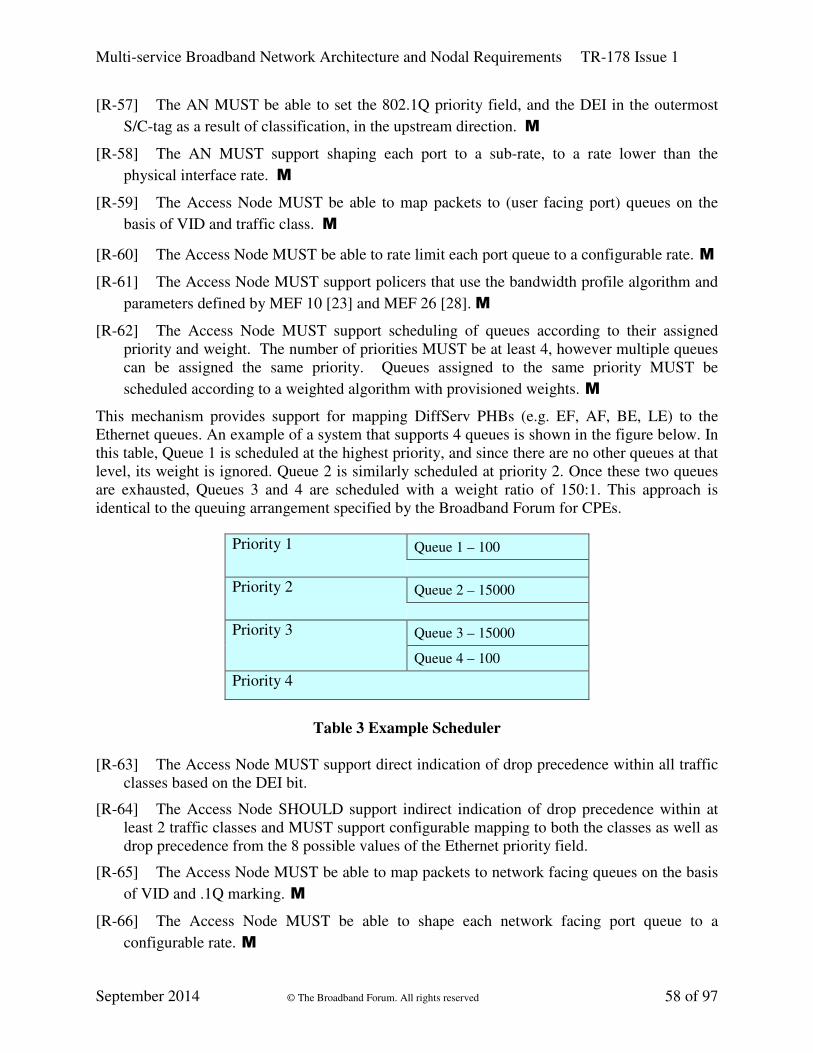
Multi-service Broadband Network Architecture and Nodal Requirements TR-178 Issue 1
September 2014 © The Broadband Forum. All rights reserved 58 of 97
[R-57] The AN MUST be able to set the 802.1Q priority field, and the DEI in the outermost
S/C-tag as a result of classification, in the upstream direction. M
[R-58] The AN MUST support shaping each port to a sub-rate, to a rate lower than the
physical interface rate. M
[R-59] The Access Node MUST be able to map packets to (user facing port) queues on the
basis of VID and traffic class. M
[R-60] The Access Node MUST be able to rate limit each port queue to a configurable rate. M
[R-61] The Access Node MUST support policers that use the bandwidth profile algorithm and
parameters defined by MEF 10 [23] and MEF 26 [28]. M
[R-62] The Access Node MUST support scheduling of queues according to their assigned
priority and weight. The number of priorities MUST be at least 4, however multiple queues
can be assigned the same priority. Queues assigned to the same priority MUST be
scheduled according to a weighted algorithm with provisioned weights. M
This mechanism provides support for mapping DiffServ PHBs (e.g. EF, AF, BE, LE) to the
Ethernet queues. An example of a system that supports 4 queues is shown in the figure below. In
this table, Queue 1 is scheduled at the highest priority, and since there are no other queues at that
level, its weight is ignored. Queue 2 is similarly scheduled at priority 2. Once these two queues
are exhausted, Queues 3 and 4 are scheduled with a weight ratio of 150:1. This approach is
identical to the queuing arrangement specified by the Broadband Forum for CPEs.
Priority 1 Queue 1 – 100
Priority 2 Queue 2 – 15000
Priority 3 Queue 3 – 15000
Queue 4 – 100
Priority 4
Table 3 Example Scheduler
[R-63] The Access Node MUST support direct indication of drop precedence within all traffic
classes based on the DEI bit.
[R-64] The Access Node SHOULD support indirect indication of drop precedence within at
least 2 traffic classes and MUST support configurable mapping to both the classes as well as
drop precedence from the 8 possible values of the Ethernet priority field.
[R-65] The Access Node MUST be able to map packets to network facing queues on the basis
of VID and .1Q marking. M
[R-66] The Access Node MUST be able to shape each network facing port queue to a
configurable rate. M

Multi-service Broadband Network Architecture and Nodal Requirements TR-178 Issue 1
September 2014 © The Broadband Forum. All rights reserved 59 of 97
5.4.4 OAM
5.4.4.1 802.1 OAM Requirements
[R-67] The AN MUST support MIPs on UNI at all 8 Maintenance Levels. M
[R-68] The AN MUST support configuration of both UP and DOWN MEPs at the UNI within
all 8 Maintenance Levels. M
[R-69] The AN MUST support configuring a MEP without sending CFM CCM’s. M
[R-70] The AN MUST support provisioning of the MEP database. M
Note: this is standard behavior i.e. a list of remote MEPs has to be manually created
[R-71] The AN SHOULD be able to build a MEP database upon receiving CFM CCM’s,
indexed by Maintenance Level and VLAN. M
Note: this is new behavior, additional to the standard
[R-72] The AN MUST be able to detect the following conditions and report them via its
instrumentation tools (SNMP MIBS and traps, Syslogs, etc): M
• Remote MEP loss of connectivity detected by loss of 3 consecutive CCMs
• Remote Port failure: reception of a CCM containing a Port Status TLV or Interface
Status TLV
• Reception of its own CC’s (indicating a loop)
• Reception of a CCM with a Lifetime of zero (Dying Gasp CCM
• Reception of a CCM with an incorrect MEPID
• Reception of a MEP with an incorrect Maintenance Association ID (MAID)
[R-73] The AN MUST be able to detect the following events and report them via its
instrumentation tools: M
• Recognition of a remote MEP for the first time
• Rediscovery of a previously expired remote MEP
• Remote Interface Up (indicated by a Interface Status TLV)
• Service Up: all MEPs configured in the crosscheck list are UP
[R-74] The AN MUST respond to CFM Loopback messages received on any of its MEPs and
MIPs, which are within the correct context of S-VLAN and Maintenance Domain. M
[R-75] The AN MUST support sending CFM Loopback messages. M
[R-76] The AN MUST support sending LinkTrace Requests. M
[R-77] The AN MUST support responding to LinkTrace Requests, by sending the appropriate
LinkTraceReplies. M
5.4.4.2 Y.1731 OAM Requirements
[R-78] The AN MUST respond to LMM and DMM OAM requests. M

Multi-service Broadband Network Architecture and Nodal Requirements TR-178 Issue 1
September 2014 © The Broadband Forum. All rights reserved 60 of 97
[R-79] The AN MUST support packet and octet counters per S-VLAN at the UP MEP of the
Inter-Carrier ME. M
5.4.4.3 802.3 OAM Requirements
[R-80] The AN MUST support 802.3 OAM / Link Level OAM as per 802.3 clause 57. M
[R-81] The AN MUST support ‘critical link events’, in terms of sending them, and acting upon
them by setting and acting upon the Remote Failure Indication Flag within the 802.3 OAM
PDU. M
[R-82] The AN MUST support sending and acting upon ‘Link Event TLV’s for the following
events: M
• Errored Frame Event: The Errored Frame Event TLV counts the number of errored
frames detected during the specified period. The period is specified by a time interval.
This event is generated if the errored frame count is equal to or greater than the specified
threshold for that period. Errored frames are frames that had transmission errors detected
at the Media Access Control sublayer.
• Errored Frame Period Event: The Errored Frame Period Event TLV counts the number of
errored frames detected during the specified period. The period is specified by a number
of received frames. This event is generated if the errored frame count is greater than or
equal to the specified threshold for that period. Errored frames are frames that had
transmission errors detected at the Media Access Control sublayer.
• Errored Frame Seconds Summary Event: The Errored Frame Seconds Summary Event
TLV counts the number of errored frame seconds that occurred during the specified
period. The period is specified by a time interval. This event is generated if the number of
errored frame seconds is equal to or greater than the specified threshold for that period.
An errored frame second is a one second interval wherein at least one frame error was
detected. Errored frames are frames that had transmission errors detected at the Media
Access Control sublayer.
5.4.4.4 E-LMI Requirements
[R-83] The AN SHOULD support the PE-side requirements out of the E-LMI Standard as
specified in MEF 16 [25]. M
[R-84] When supporting the E-LMI function, The AN MUST support communication of the
following entities to the customer equipment attached to the U interface: M
• Remote UNI expected count
• Remote UNI active count
• Remote UNI name
• Remote UNI status (up, down, admin down, excessive FCS failures)
• Local UNI name
• EVC ID
• EVC Type (point-to-point, multipoint)
• EVC Status (active, partially active, inactive)
• CE-VLAN to EVC map type (Bundling / All-to-one Bundling / Multiplexing)
• CE-VLAN to EVC map

Multi-service Broadband Network Architecture and Nodal Requirements TR-178 Issue 1
September 2014 © The Broadband Forum. All rights reserved 61 of 97
5.4.4.5 OAM interworking requirements
[R-85] The AN MUST support CFM to E-LMI interworking allowing the communication of
events in CFM to E-LMI. Use cases include : M
• remote MEP timeout
• remote MEP UNI name
• remote MEP port status
Note: how the CE reacts to this is out of scope of this document.
[R-86] The AN MUST support 802.3 Link level OAM to CFM interworking allowing
communication of events in 802.3 Link level OAM to CFM. Use cases include: M
• reception of Dying Gasp
• exceeded local monitoring threshold
• remote loopback test
Note: how the CE reacts to this is out of scope of this document.
5.4.5 Resilience
The AN plays an active role in proving the resilience, redundancy and convergence function in
cooperation with the rest of the aggregation network.
The AN supports dual homing both to a single and two different aggregation nodes.
Convergence after link and/or aggregation node failure should result in a maximum loss of
connectivity of 1 second. In order to achieve that, the following need to be taken into account:
• Multiple I-NNI interfaces configured for active/stand by operation
• Multiple I-NNI interfaces configured for load balancing operation
• Multiple I-NNI interfaces with Ethernet link aggregation capabilities
• L2 Ethernet protocols that will ensure loop-free topology, ring protection, deterministic
convergence upon fault detection
[R-87] The AN MUST support link aggregation as per 802.1AX [6] . M
[R-88] The AN MUST support Multiple Spanning Tree as per 802.1D [2]. M
[R-89] An AN with multiple uplinks (not members of the same 802.1AX link aggregation
group) MUST support VLAN aware bridging at the Va reference point. M
[R-90] The AN MUST support LACP according to 802.1AX. M
[R-91] The AN MUST support Ethernet Ring Protection Switching as per G.8032 [14]. M
[R-92] The Ethernet Access Node MUST support LAG with active/standby and active/active
groups. M
5.4.6 Multicast
Multicast forwarding is now a well-established method to deliver a common packet stream to
multiple receivers efficiently. The AN is expected to support a certain number of features that

Multi-service Broadband Network Architecture and Nodal Requirements TR-178 Issue 1
September 2014 © The Broadband Forum. All rights reserved 62 of 97
enable the delivery of multicast services in an efficient way, and that will allow multicast to be
also offered as a wholesale service.
Multicast requirements for the AN mainly address the (active and passive) interaction of IGMP
messages with the AN’s (multicast) forwarding decisions. Information present at the IP Layer is
used to build filters to efficiently control the multicast forwarding behavior in the AN and within
the corresponding access architecture.
IP multicast routing protocols are run by nodes external to the AN: these could be the BNG that
will terminate PIM (SM or SSM) in a typical multicast deployment, or a business customer
router (in a multicast VPN scenario) that will run its own multicast routing protocol (again likely
to be PIM SM or SSM).
The AN, as an L2 Ethernet node needs to support IGMP transparent snooping or IGMP proxy
reporting (with report suppression), thus letting an operator use the flavor of IGMP manipulation
that best suits their multicast architecture and needs.
Multicast delivery of residential services may use a dedicated Multicast VLAN (MVLAN) which
transports multicast services in a separate broadcast domain and uses a ‘leaking’ mechanism to
forward multicast data and control packets from the network to the user. User initiated IGMP
signaling upstream will also be leaked from the user port onto this Multicast VLAN. Note that a
Multicast VLAN is just a standard S-VLAN, albeit with a point to multipoint topology. The
support of multiple MVLANs is required in order to offer multicast as a wholesale service. It
must be possible to map multicast groups to Multicast VLANs, including wildcard behavior (i.e.
‘any’).
The multicast architecture described here also relies on the IGMP capabilities offered by the RG
or the CPE, and in the context of residential services, it is assumed that a RG supports the
multicast requirements already stated in TR-101i2.
The multicast forwarding paradigms considered in this document are:
� Single Multicast VLAN
� Multiple Multicast VLANs
� Sharing of Multicast and Unicast VLAN (N:1 case)
[R-93] The AN MUST support, on a per port basis, the identification and processing of IGMP
v2 and v3 messages. M
[R-94] The AN MUST be able to drop all IGMP messages received on a per port and/or per
VLAN basis. M
[R-95] The AN MUST support a mechanism to stop user ports injecting multicast traffic into
the aggregation network. This behavior MUST be configurable on a per port and/or per
VLAN basis. M
[R-96] For security purposes, the AN MUST drop any user-initiated IGMP Leave messages
for group ‘0.0.0.0’. M

Multi-service Broadband Network Architecture and Nodal Requirements TR-178 Issue 1
September 2014 © The Broadband Forum. All rights reserved 63 of 97
[R-97] The AN MUST be able to discard IGMP queries received from user-facing ports on a
multicast VLAN. M
[R-98] The AN MUST be able to rate limit IGMP messages received from user-facing ports on
a multicast VLAN on a per port basis. M
[R-99] The AN MUST support the configuration of multiple multicast VLANs on the network
facing interface. M
[R-100] The AN MUST support the configuration, for a given user port, of the associated
Multicast VLAN. M
[R-101] The AN MUST support the configuration of IP multicast groups and ranges of
multicast groups attached to a multicast VLAN based on: M
• Source address matching (in the case of IGMP v3)
• Group address matching
[R-102] It MUST be possible to configure the option “ANY” allowing every IP multicast group
to be attached to the multicast VLAN. When the option ANY is configured the well-known
and reserved groups (224/8) or protocols must not be forwarded through the MVLAN. M
[R-103] The AN MUST allow IP multicast group address spaces in different MVLANs to
overlap. M
[R-104] The AN MUST allow IP multicast source addresses in different MVLANs to overlap.
M
[R-105] The AN MUST support transparent IGMP Snooping. M
[R-106] The AN MUST support IGMP Snooping with proxy reporting. M
[R-107] According to the type of IGMP manipulation configured for a given MVLAN in the
upstream direction, the AN MUST send all the IGMP traffic received on the U-interface and
destined to multicast groups to be handled by the MVLAN configured for that port, to the
Va-reference point and attach the proper Tags and VLAN VIDs. M
[R-108] The AN MUST forward IGMP downstream messages and appropriate IP multicast
traffic transported within a certain MVLAN, to the U-interfaces attached to that MVLAN
after the proper user port tagging manipulation. M
[R-109] The AN MUST support the configuration, on a per port basis, of the maximum number
of simultaneous multicast groups allowed on a port. M
[R-110] The AN MUST support IGMP immediate leave. M
[R-111] The AN MUST support IGMP FAST leave. M
[R-112] The AN MUST support marking of user-initiated IGMP traffic with Ethernet priority
bits. M

Multi-service Broadband Network Architecture and Nodal Requirements TR-178 Issue 1
September 2014 © The Broadband Forum. All rights reserved 64 of 97
[R-113] The Access Node SHOULD support IGMPv3 with L3 forwarding according to the L3
Multicast architecture as defined by TR-145. M
Pre-configured delivery of multicast groups to the Access Node is a mechanism to minimize the
channel-change latency in a network using IGMP snooping. This requires the Access Node to
request the pre-configured multicast channels even when there are no subscriber ports requesting
the channel. Individual users then connect to these channels using the normal IGMP method.
[R-114] The Access Node MUST support a configurable list of <Group, Source> pairs for pre-
configured multicast channels. M
[R-115] The Access Node MUST join all pre-configured channels regardless of the IGMP
membership state of subscriber interfaces. M
Further, a subset of these pre-configured channels must be able to be forwarded to all users on a
given multicast VLAN to support a broadcast-like service, e.g. for an EPG.
[R-116] The Access Node MUST support static multicast replication whereby specified
Multicast traffic is always replicated and forwarded to all U-interfaces that are members of a
given multicast VLAN. M
5.4.7 DHCP/PPPoE Processing
5.4.7.1 Overall
Port identification is used in conjunction with a DHCP Relay or PPPoE Intermediate Agent.
These entities insert port-specific information in DHCP Discover or PPPoE PADI messages to
identify an access port or user port. This section summarizes requirements for Ethernet
Aggregation and Access (TR-101i2, TR-147, TR-177) and GPON based Access (TR-156i3)
mainly by reference. Basic functionality is not repeated here.
5.4.7.2 PORT Specific configuration & conventions
5.4.7.2.1 Access Loop ID
[R-117] The Access Node Circuit ID MUST be configurable using any of the printable
characters from the ASCII Range. M
[R-118] For each protocol that requires Access Loop ID the slot/port numbering MUST be
configurable to start at either 0 or 1. M
[R-119] The slot/port numbering MUST be configurable to either use, or not use, leading
zeroes. M
5.4.7.2.2 Remote ID according to IETF RFC 3046 [49]
The Remote ID is a unique ID per operator domain which is not linked to an Access Node
topology. Therefore this field has to be freely configurable by the operator via NMS, at the time
the customer port is provisioned. Further conventions for the Remote ID are out of scope of this
document.

Multi-service Broadband Network Architecture and Nodal Requirements TR-178 Issue 1
September 2014 © The Broadband Forum. All rights reserved 65 of 97
[R-120] The Remote ID MUST be configurable via an external provisioning tool (e.g. NMS) for
each AN port. M
5.4.7.2.3 Line Parameters
[R-121] The AN MUST support the line parameters in table 3, TR-101i2 for DHCPv4 Option
82. M
[R-122] The AN MUST support the line parameters in table 3, TR-101i2 for DHCPv6 Option
17. M
[R-123] The AN MUST support the line parameters in table 3, TR-101i2 PPPoE Intermediate
Agent-Vendor-specific Tag. M
[R-124] The AN MUST be able to send a configured subset of the parameters in table 3, TR-
101i2. M
5.4.7.2.4 Operation Modes
[R-125] The AN MUST support the activation / deactivation of the DHCP Relay/PPPoE
Intermediate Agent (IA) function per S-VLAN. M
[R-126] The DHCP Relay/ PPPoE IA function MUST be able to parse frames containing up to
2 VLAN tags. M
5.4.7.3 DHCP Relay Agent
[R-127] All DSL-based ANs MUST support the requirements in TR-101i2, section 3.8.2 and
section 3.9.
[R-128] All GPON-based ANs MUST support the requirements in TR-156i3, section 5.7.
[R-129] The DHCP relay agent in the AN MUST support the Circuit ID and the Remote ID as
described in BBF TR-101i2 and TR-156i3. M
[R-130] If the DHCPv4 Relay Agent function is deactivated, the AN MUST transparently
forward DHCPv4 packets containing Option 82. M
5.4.7.4 PPPoE Intermediate Agent
[R-131] All DSL-based ANs MUST support the requirements in TR-101i2, section 3.9.2 and
section 3.9.3.
[R-132] All GPON-based ANs MUST support the requirements in TR-156i3, section 5.7.
[R-133] The AN MUST support the PPPoE Intermediate Agent function for dual stack
IPv4/IPv6.
[R-134] If the Intermediate Agent function is deactivated, the AN MUST transparently forward
the PPPoE vendor-specific tag. M
5.4.8 Security
There is a need to protect aggregation nodes and MS-BNGs from multicast and broadcast
packets injected at user ports. Furthermore unknown unicast packets will typically not be seen in
residential broadcast deployment.

Multi-service Broadband Network Architecture and Nodal Requirements TR-178 Issue 1
September 2014 © The Broadband Forum. All rights reserved 66 of 97
When the security requirements listed in this section are enabled, protocol-specific interworking
functions are invoked to handle downstream broadcast and multicast (DHCP, ARP, IGMP,
OAM), as well as providing ways to statically define L2 forwarding entries. In case these
interworking functions are invoked, control plane rate limiting must be performed. Static MAC-
address entries can be used to ensure delivery to MS-BNGs. In residential environments there is
also no need for subscribers to see other subscriber’s MAC-addresses.
[R-135] The EAN MUST be able to prevent flooding of unknown unicast packets on a per
VLAN basis
[R-136] The EAN MUST be able to drop upstream broadcast traffic on a per VLAN basis
[R-137] The EAN MUST be able to drop upstream L2 multicast traffic on a per VLAN basis.
When this is enabled, protocol-specific interworking functions MUST be invoked to handle
broadcast and multicast (DHCP, ARP, IGMP, OAM)
[R-138] The EAN MUST be able to rate-limit L2 multicast and broadcast traffic received on a
user port.
[R-139] The EAN MUST support installing static (MAC-address, Port) entries into the
forwarding table, on a per VLAN basis. These static MAC-address entries MUST NOT be
subsequently overwritten by dynamic learning.
[R-140] The EAN MUST support installing static multicast MAC-address entries into the
forwarding table, indicating the multicast address and the port flood-set, on a per VLAN
basis
[R-141] The EAN MUST be able to rate-limit the traffic destined to its control plane (PPPoE
Agent, DHCP L2 Agent, IGMP, ARP Proxy, etc) that is received on user-ports.
[R-142] The EAN MUST support Split-Horizon L2 forwarding upstream, while allowing
normal destination-based MAC-address forwarding downstream. This behavior MUST be
configurable on a per VLAN basis. This prevents upstream traffic (towards IP Service
Edges) being seen by other subscribers attached to the same VLAN.
There is a need to limit the number of MAC-addresses learned per port, while dropping packets
with a source MAC-address that has not been previously learned on the port, as well as locking a
MAC-address to a certain port. This prevents MAC-spoofing attacks. Another approach is to
authenticate access to the user port through 802.1x.
Note: a static MAC-address entry for the MS-BNGs MAC-address prevents someone behind a
user port spoofing the MS-BNG’s MAC-address.
[R-143] The EAN MUST be able to limit the number of MAC-addresses learned on a user port.
This limit MUST be configurable on a per user port basis. In case the limit threshold has
been reached, the EAN MUST drop packets sourced from any unknown MAC-addresses in
the upstream direction.
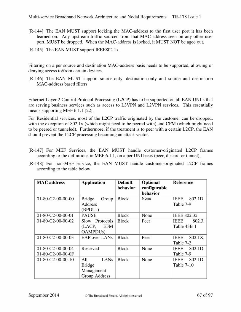
Multi-service Broadband Network Architecture and Nodal Requirements TR-178 Issue 1
September 2014 © The Broadband Forum. All rights reserved 67 of 97
[R-144] The EAN MUST support locking the MAC-address to the first user port it has been
learned on. Any upstream traffic sourced from that MAC-address seen on any other user
port, MUST be dropped. When the MAC-address is locked, it MUST NOT be aged out,
[R-145] The EAN MUST support IEEE802.1x.
Filtering on a per source and destination MAC-address basis needs to be supported, allowing or
denying access to/from certain devices.
[R-146] The EAN MUST support source-only, destination-only and source and destination
MAC-address based filters
Ethernet Layer 2 Control Protocol Processing (L2CP) has to be supported on all EAN UNI’s that
are serving business services such as access to L3VPN and L2VPN services. This essentially
means supporting MEF 6.1.1 [22].
For Residential services, most of the L2CP traffic originated by the customer can be dropped,
with the exception of 802.1x (which might need to be peered with) and CFM (which might need
to be peered or tunneled). Furthermore, if the treatment is to peer with a certain L2CP, the EAN
should prevent the L2CP processing becoming an attack vector.
[R-147] For MEF Services, the EAN MUST handle customer-originated L2CP frames
according to the definitions in MEF 6.1.1, on a per UNI basis (peer, discard or tunnel).
[R-148] For non-MEF service, the EAN MUST handle customer-originated L2CP frames
according to the table below.
MAC address Application Default
behavior
Optional
configurable
behavior
Reference
01-80-C2-00-00-00 Bridge Group
Address
(BPDUs)
Block None IEEE 802.1D,
Table 7-9
01-80-C2-00-00-01 PAUSE Block None IEEE 802.3x
01-80-C2-00-00-02 Slow Protocols
(LACP, EFM
OAMPDUs)
Block Peer IEEE 802.3,
Table 43B-1
01-80-C2-00-00-03 EAP over LANs Block Peer IEEE 802.1X,
Table 7-2
01-80-C2-00-00-04 -
01-80-C2-00-00-0F
Reserved Block None IEEE 802.1D,
Table 7-9
01-80-C2-00-00-10 All LANs
Bridge
Management
Group Address
Block None IEEE 802.1D,
Table 7-10

Multi-service Broadband Network Architecture and Nodal Requirements TR-178 Issue 1
September 2014 © The Broadband Forum. All rights reserved 68 of 97
01-80-C2-00-00-20 GMRP Block None IEEE 802.1D,
Table 12-1
01-80-C2-00-00-21 GVRP Block None IEEE 802.1Q,
Table 11-1
01-80-C2-00-00-22 -
01-80-C2-00-00-2F
Reserved GARP
Application
addresses
Block Forward IEEE 802.1D,
Table 12-1
01-80-C2-00-00-3y
(y = MD level)
CFM Forward Block IEEE 802.1Q,
Table 8-15
Table 4 Default and/or configurable filtering behavior of reserved group MAC destination
addresses according to TR-101i2
[R-149] The EAN MUST support rate-limiting control-plane L2CP traffic when peering with
that particular L2CP.
DHCP processing can also be an attack vector. The DHCP Layer 2 Relay needs to be enhanced
with extra security features. The state created by the Layer 2 DHCP Relay can be leveraged by
features that in turn prevent IP and ARP Spoofing.
[R-150] A server-originated broadcast DHCP packet MUST NOT be bridged to untrusted user-
facing ports by an EAN except through the action of the Layer 2 DCHP relay agent.
Through examination of option-82 and/or the chaddr field, the Layer 2 DHCP relay agent
MUST only transmit these packets, after removal of option-82, to the untrusted interface for
which it is intended.
[R-151] The EAN MUST snoop all DHCP traffic, when performing the function of a Layer 2
DHCP relay agent, and filter out any DISCOVER and REQUEST packets from the access
loop designed to spoof relayed packets. This would include packets with nonzero ‘giaddr’,
and REQUEST packets with zero ‘ciaddr’. This requirement refers to both unicast and
broadcast DHCP packets.
[R-152] The EAN MUST, when performing the function of a Layer 2 DHCP relay agent,
discard any broadcast or unicast DHCP request packet from an untrusted user-facing port
that contains option-82.
[R-153] The EAN MUST, when performing the function of a Layer 2 DHCP relay agent, only
forward DHCP requests to the upstream designated port(s) to prevent flooding or spoofing.
[R-154] The EAN MUST inspect upstream and downstream DHCP packets, and discover
mapping of IP address to MAC address of subscribers
[R-155] The EAN MUST NOT send downstream broadcast ARP requests on access ports that
do not have the associated requested IP address, by using the mapping derived in [R-154].
[R-156] The EAN MUST be able to filter upstream ARP replies that do not match the mapping
derived in [R-154].

Multi-service Broadband Network Architecture and Nodal Requirements TR-178 Issue 1
September 2014 © The Broadband Forum. All rights reserved 69 of 97
[R-157] The EAN MUST be able to dynamically install source IP-address filters, by using the
mapping derived in [R-154]. This prevents IP-address spoofing.
[R-158] The EAN MUST be configurable with a list of IP addresses associated with user port
and VLAN, to be used for users with static IP configurations.
5.5 MPLS enabled Access Node Requirements
The requirements in this section apply to MPLS enabled Access Nodes (MANs) and BNG
embedded Access Node (BANs). The MPLS-related requirements correspond to the MPLS
Adaptation Module (MAM) in TR-145. Requirements for a seamless MPLS architecture are also
covered.
The MPLS requirements listed in the sections below constitute a profile of the TR-221
requirements when applied to MANs and BANs. Hence, the alignment and reference to TR-221
is indicated where applicable.
5.5.1 General Requirements
[R-159] The MPLS enabled Access Node MUST support all the capabilities of an Ethernet
Access Node.
[R-160] The MPLS enabled Access Node MUST support the MPLS architecture according to
RFC 3031.
[R-161] The MPLS enabled Access Node MUST support MPLS label encoding according to
RFC 3032. M
[R-162] The MPLS Data Plane MUST support IPv4 FEC-to-NHLFE (FTN) classification. M
[R-163] The MPLS Data Plane MUST support IPv6 FEC-to-NHLFE (FTN) classification. M
[R-164] The MPLS Control Plane and Management Plane MUST be supported over IPv4. M
[R-165] The MPLS Control Plane and Management Plane MUST be supported over IPv6. M
[R-166] [R-164] and [R-165] MUST be able to be supported simultaneously. M
[R-167] The MPLS enabled Access Node MUST support the configuration of IPv4 and IPv6
loopback and interface addresses. M
[R-168] The MPLS enabled Access Node SHOULD support /31 IPv4 interface addresses at the
uplink as per RFC 3021 [46]. M
[R-169] The MPLS enabled Access Node MUST support static routing (i.e. default routes). M
[R-170] The MPLS enabled Access Node MUST support statically provisioned LSPs in an LER
role. M
[R-171] The MPLS enabled Access Node MUST support LDP as per RFC 5036 [80] using the
profiling defined in draft-ietf-seamless-mpls [37]. M
The default label retention mode is conservative.
The default label distribution control mode is ordered.

Multi-service Broadband Network Architecture and Nodal Requirements TR-178 Issue 1
September 2014 © The Broadband Forum. All rights reserved 70 of 97
[R-172] The MPLS enabled Access Node MUST support Inter-area LDP as per RFC 5283 [82].
M
[R-173] The MPLS enabled Access Node MUST support configuration of LDP timer values
with a one second granularity. M
[R-174] The MPLS enabled Access Node MUST support MPLS Pseudowires (PW) as per RFC
3985 [61].
[R-175] The MPLS enabled Access Node MUST be able to act as a T-PE as per RFC 6073 [91].
M
[R-176] The MPLS enabled Access Node MUST support FEC-Types 128 and 129. M
Note: FEC129 provides scalable endpoint identification and is useful in large inter-domain
scenarios where Pseudowires are to be established between selected local and remote provider
edge (PE) nodes.
[R-177] The MPLS enabled Access Node MUST support globally unique Attachment
Individual Identifiers (AII) to address PW SAI and PW TAI as per RFC 5003 [79]. M
[R-178] The MPLS enabled Access Node MUST support LDP for PW signaling as per RFC
4447 [68]. M
[R-179] The MPLS enabled Access Node MUST support statically provisioned Pseudowires. M
[R-180] The MPLS enabled Access Node MUST support TTL handling as per RFC 3443 and
RFC 4905 [77]. M
[R-181] The MPLS enabled Access Node SHOULD support Pseudowire Control Word per
RFC 4385 [66].
[R-182] Use of the Pseudowire Control Word MUST be supported for all PW types and MUST
be configurable per Pseudowire. M
5.5.2 Layer 2 Requirements
When referring to Figure 15, one can see that the MAN is composed of Ethernet related
functions and MPLS adaption functions. The Ethernet adaption functions can manipulate S- and
C-VLAN tags arriving at the U1 reference points, as per the requirements of section 5.5.1.
Internally the MPLS adaption functionality will look at S-VLANs only.
[R-183] The MPLS enabled Access Node MUST support VPWS as per RFC 4448 [69] for S-
VLANs only.
[R-184] The MPLS enabled Access Node MUST support multiplexing non-service delimiting
S-tags into a single PW.
These tags may have been added or modified by the Ethernet adaption function, for example
to denote service.

Multi-service Broadband Network Architecture and Nodal Requirements TR-178 Issue 1
September 2014 © The Broadband Forum. All rights reserved 71 of 97
[R-185] The MPLS enabled Access Node MUST support all Ethernet native service processing
functions as per RFC 4448 and TR-221 section 8.3.1. The behavior MUST be configurable
per service instance. M
[R-186] The MPLS embedded Access Node for VPWS encapsulation MUST support
procedures and requirements as per Section 11.1.3/TR-224. M
[R-187] The MPLS embedded Access Node for Ethernet Private Line (EPL) MUST support
requirements as per Section 11.2.1/TR-224. M
[R-188] The MPLS embedded Access Node for Ethernet Virtual Private Line (EVPL) MUST
support requirements as per Section 11.3.1/TR-224. M
Note: as a result, for a 1:1 VLAN service or TLS, the aggregation of traffic of multiple clients
into one Pseudowire can be supported with no MAC address-based forwarding in the Access
Node.
[R-189] The MPLS enabled Access Node MUST support VPLS PE functionality for S_VLAN
only. M
[R-190] The MPLS enabled Access Node MUST support H-VPLS MTU functionality for S-
VLAN only. M
[R-191] The MPLS enabled Access Node MUST support multiplexing multiple S-tags into a
single VPLS instance.
[R-192] The MPLS enabled Access Node MUST support MAC-Address Withdrawal as per
RFC 4762 [74] section 6.2. M
[R-193] The MPLS enabled Access Node SHOULD support MAC-Address Withdrawal
optimization as per RFC 4762 section 6.2 to enable PE devices to remove only the MAC
addresses that need to be relearned. M
5.5.3 Load Balancing
[R-194] The MPLS enabled Access Node MUST support flow-aware transport of Pseudowires
according to RFC 6391 [98]. M
[R-195] The MPLS enabled Access Node SHOULD support “Entropy Labels in MPLS” as per
RFC 6790 [104]. M
5.5.4 Resilience
[R-196] The MPLS enabled Access Node MUST support Multi-Homing. M
[R-197] The MPLS enabled Access Node SHOULD support P redundancy as per RFC 6718
[103] and RFC 6870 [106]. M
[R-198] The MPLS enabled Access Node MUST be able to change the default route when the
default interface goes down. M

Multi-service Broadband Network Architecture and Nodal Requirements TR-178 Issue 1
September 2014 © The Broadband Forum. All rights reserved 72 of 97
[R-199] The MPLS enabled Access Node MUST support mechanisms enabling fast data plane
failure detection using BFD as per RFC 5884 [89]. M
[R-200] For End to End Tunnel Resilience, the MPLS enabled Access Node MUST support
single hop as per RFC 5881 [87]. M
[R-201] For End to End Tunnel Resilience, the MPLS enabled Access Node MUST support
Multi-hop option as per RFC 5883 [88]. M
[R-202] The MPLS enabled Access Node SHOULD support LDP Graceful Restart as per RFC
3478 [56] in helper mode. M
5.5.5 OAM
[R-203] The MPLS enabled Access Node MUST support ICMP Ping and TraceRoute as per
RFC 792 [39] (IPv4) and RFC 4443 [67] (IPv6) with MPLS extensions as per RFC 4950
[78]. M
[R-204] The MPLS enabled Access Node MUST support Attachment Circuit / Pseudowire
OAM message mapping as per RFC 6310 [94]. M
[R-205] The MPLS enabled Access Node MUST support Attachment Circuit / Pseudowire
Ethernet OAM message mapping as per RFC 7023 [107]. M
[R-206] The MPLS enabled Access Node MUST support activation and deactivation of OAM
message mapping per Pseudowire. M
[R-207] The MPLS enabled Access Node MUST support MPLS Ping as per RFC 4379 [65]. M
[R-208] The MPLS enabled Access Node MUST support MPLS TraceRoute as per RFC 4379.
M
[R-209] The MPLS enabled Access Node MUST support enhanced MPLS Ping and TraceRoute
as per RFC 6424 [99], enabling a TraceRoute request to correctly traverse MPLS tunnels
with proper FEC and label validations. M
[R-210] The MPLS enabled Access Node SHOULD support Return Path Specified LSP Ping as
per RFC 7110 [108], enforcing a specific return path can be used to verify bidirectional
connectivity. M
[R-211] The MPLS enabled Access Node MUST support PW OAM VCCV, as per
requirements [R-16] and [R-20] of TR-221. M
[R-212] The MPLS enabled Access Node MUST support Multi-Segment PW OAM as per
section 5.2.3.2 and requirements [R-21], [R22], [R23], [R26] and [R-27] of TR-221. M
[R-213] The MPLS enabled Access Node MUST support VCCV-BFD as per requirement [R-17]
of TR-221. M
[R-214] In an ECMP enabled MPLS network, an MPLS enabled Access Node MUST support
the tracing procedure for a single segment Pseudowire. M

Multi-service Broadband Network Architecture and Nodal Requirements TR-178 Issue 1
September 2014 © The Broadband Forum. All rights reserved 73 of 97
[R-215] The MPLS enabled Access Node SHOULD support GAL and G-ACh as per RFC 5586
[85]. M
[R-216] When PWs are established using static provisioning, the MPLS enabled Access Node
MUST support fault notification as per requirements R-18 and R-19 of TR-221. M
[R-217] The MPLS enabled Access Node SHOULD support loss and delay measurements of
LSP and Pseudowires as per RFC 6374 [96]. M
[R-218] The MPLS enabled Access Node MUST support performance counters per p-Bit per
Infrastructure Virtual Circuit (IVC). M
5.5.6 QoS
[R-219] The MPLS enabled Access Node supporting MPLS L2VPN, MUST support
requirements [R-47] to [R-52] of TR-221 (section 5.4). M
5.5.6.1 Tunnel COS Mapping and marking
[R-220] The MPLS enabled Access Node MUST support tunnel COS mapping and marking as
per requirements [R-53] to [R-57] of TR-221 (section 5.4.1). M
5.5.6.2 PW COS Mapping and marking
[R-221] The MPLS enabled Access Node MUST support PW COS mapping and marking as per
requirements [R-58] to [R-60] of TR-221 (section 5.4.2). M
5.5.7 MPLS related multicast requirements
[R-222] The MPLS enabled Access Node SHOULD support the application of multicast within
VPLS as per RFC 7117 [109]. M
[R-223] The MPLS enabled Access Node MUST support IGMPv3 and MLDv2 signaling over
both active and standby Pseudowires. M
[R-224] The MPLS enabled Access Node SHOULD support LDP extensions for point-to-
multipoint and multipoint-to-multipoint LSPs (mLDP) as per RFC 6388 [97]. C
5.6 BNG embedded Access Node Requirements
The MPLS requirements listed in the sections below constitute a profile of the TR-221
requirements when applied to a MPLS-enabled, BNG-embedded AN. The alignment and
referencing to TR-221 is indicated in the requirements where applicable.
[R-225] The BNG embedded Access Node MUST support all the capabilities of an MPLS
enabled Access Node as defined in this document.
Similarly, the BNG embedded Access Node needs to incorporate some of the MS-BNG
functions specified in section 7.1 as listed below.
[R-226] The BNG embedded Access Node MUST support following MS-BNG requirements:

Multi-service Broadband Network Architecture and Nodal Requirements TR-178 Issue 1
September 2014 © The Broadband Forum. All rights reserved 74 of 97
� [R-283] to [R-362] and [R-371] to [R-373] in section 7.1 Generic MS-BNG
requirements
� [R-374] to [R-378] in section 7.2 Additional MS-BNG requirements when deployed
at the edge in a hierarchy
5.6.1 PSN tunnel related features
5.6.1.1 Routing
[R-227] The BNG embedded Access Node MUST support the exchange of routing information
via both RFC 2328 [42] for OSPF, and RFC 1195 [40] IS-IS for an LSP control plane. M
5.6.1.2 MPLS Traffic Engineering
The following requirements apply only if traffic engineering is supported.
[R-228] The BNG embedded Access Node MUST support RSVP-TE as per RFC 3209 [51] on
the LSP. M
[R-229] The BNG embedded Access Node MUST support IGP-TE (both RFC 3784 [59] ISIS-
TE and RFC 3630 [58] OSPF-TE) for a TE-LSP control plane. M
5.6.1.3 Multi-area LSP Signaling
Operators may require multi-area networks for scalability. Link state Interior Gateway Protocols
(IGPs) such as OSPF (RFC 2328) and IS-IS (RFC 1195) allow systems to be divided into areas
or levels to increase routing scalability within a domain.
An MPLS Domain is any collection of network elements within a common realm of address
space or path computation responsibility. Examples of such domains include Autonomous
Systems, Interior Gateway Protocol (IGP) routing areas, and GMPLS overlay networks.
Inter-area LSP (that is, LSPs that traverse at least two IGP areas) signalling extensions are
required to ensure MPLS connectivity between PEs located in distinct IGP areas.
[R-230] The BNG embedded Access Node SHOULD support establishing RSVP-TE LSPs
using LSP hierarchy as per RFC 4206 [63]. C
[R-231] The BNG embedded Access Node SHOULD support establishing RSVP-TE LSPs
using LSP stitching as per RFC 5150 [84]. C
5.6.1.4 Inter-Domain Routing
For scalability, the overall MPLS network is decomposed into multiple MPLS domains. The
inter-domain routing is used to establish the routing and forwarding hierarchy.
RFC 3107 [50] defines procedures for having BGP allocate labels for routes between BGP peers.
By implementing RFC 3107 at the aggregation point, BGP label allocation eliminates the need
for core devices to learn all the prefixes in the access domain as routes are summarized.

Multi-service Broadband Network Architecture and Nodal Requirements TR-178 Issue 1
September 2014 © The Broadband Forum. All rights reserved 75 of 97
[R-232] The BNG embedded Access Nodes MUST support using BGP-4 for label distribution
as per RFC 3107. M
5.6.1.5 Resiliency
Resilient networks must provide deterministic end-to-end service restoration. The functions that
help to achieve this are the speedy detection and location of failures and the recovery actions
needed to reroute and restore service.
[R-233] The BNG embedded Access Node MUST support Fast ReRoute (FRR) around link
failure or router failure as per RFC 4090 [62]. M
[R-234] The BNG embedded Access Node MUST support Facility backup function as defined
in Section 3.2/RFC 4090. M
[R-235] The BNG embedded Access Node SHOULD support One to One backup as defined in
Section 3.1/RFC 4090. M
[R-236] The BNG embedded Access Node MUST support loop-free alternate (LFA) for ISIS,
OSPF and LDP as per RFC 5286 [83]. M
[R-237] The BNG embedded Access Node MUST support RSVP-TE graceful restart as per
Section 9/RFC 3473 [55] as well as graceful restart for the routing protocols upon which
RSVP-TE path computation depends. M
[R-238] The BNG embedded Access Node SHOULD support OSPF graceful restart as per RFC
3623 [57]. M
[R-239] The BNG embedded Access Node SHOULD support IS-IS graceful restart as per RFC
3847 [60]. M
5.6.1.6 P behavior
It may be desirable for the AN to behave as a transit LSR in the case of subtended MPLS ANs in
an MPLS Access Node cluster, or a flat MPLS architecture for mobile backhauling; for instance
with mobile CSGs as LERs connected to the AN behaving as a P router, as described in TR-221.
[R-240] The BNG embedded Access Node SHOULD support P behavior (Label Switch Router)
between internal network to network interfaces. M
5.6.2 Additional L2 service related features
5.6.2.1 Switching PE for Multi-Segment Pseudowires
A typical Use Case for the following requirements is mobile backhauling, with mobile CSGs as
Terminating PEs, connected to the AN behaving as a Switching PE.
[R-241] The BNG embedded Access Node SHOULD support Multi-Segment Pseudowire
switching between internal network and network interfaces as per RFC 5659 [86] and RFC
6073 [91]. M

Multi-service Broadband Network Architecture and Nodal Requirements TR-178 Issue 1
September 2014 © The Broadband Forum. All rights reserved 76 of 97
5.6.2.2 BGP signaled VPLS
[R-242] The MPLS enabled Access Node SHOULD support BGP-based auto-discovery for
LDP signaled VPLS as per RFC 6074 [92]. M
[R-243] The BNG embedded Access Node MUST support BGP signaling and Auto-Discovery
for VPLS as per RFC 4761 [73]. M
[R-244] The BNG embedded Access Node implementing BGP signaling for VPLS SHOULD
support multi homing as per draft-ietf-l2vpn-multihoming [38]. M
5.6.2.3 VPWS Signaling with BGP and Auto-Discovery
IP-MPLSF 22.0.0 “BGP auto-discovery and signaling for VPWS-based VPN services” [20],
provides a specification for the setup of VPWS Pseudowires. That specification supports both
auto-discovery and signaling.
[R-245] The BNG embedded Access Node for VPWS signaling SHOULD support IP-MPLSF
22.0.0 [20] with encapsulation type values 4 and 5. M
[R-246] The BNG embedded Access Node for VPWS encapsulation MUST support the
procedures and requirements of Section 11.1.3/TR-224.
[R-247] The BNG embedded Access Node for Ethernet Private Line (EPL) MUST support the
requirements of Section 11.2.1/TR-224.
[R-248] The BNG embedded Access Node for Ethernet Virtual Private Line (EVPL) MUST
support the requirements of Section 11.3.1/TR-224.
5.6.2.4 BGP auto-discovery for LDP signaled VPLS
BGP based PE auto-discovery can ease VPN provisioning by avoiding the need to configure any
PE with the identity of other PEs in that VPN instance, and by automatically establishing the
signaling sessions and individual Pseudowires. It can also make VPN configuration more
flexible, by avoiding the need to change the configuration on any existing PEs when adding a
new PE in a VPN.
For VPLS having Hub and Spoke connectivity, BGP auto-discovery simplifies the provisioning
of Hub PEs. For VPLS having Any-to-Any connectivity, BGP auto-discovery simplifies the
provisioning of all PEs.
It is desirable to have that capability on BNG embedded Access Nodes, however it is understood
these features might not be supportable on small sized Access Nodes.
[R-249] The BNG embedded Access Node MUST support BGP-based auto-discovery for LDP
signaled VPLS as per RFC 6074 [92]. M
[R-250] The BNG embedded Access Node implementing LDP signaling for VPLS SHOULD
support multi homing as per draft-ietf-l2vpn-multihoming [38]. M
5.6.3 L3 service related features for the Access Node
Potential use cases for such features on the Access Node are retail residential services, business
services, or IP transport networks for mobile backhaul.

Multi-service Broadband Network Architecture and Nodal Requirements TR-178 Issue 1
September 2014 © The Broadband Forum. All rights reserved 77 of 97
5.6.3.1 IPv4 VPN
[R-251] The BNG embedded Access Node MUST support BGP and MP-BGP as per RFC 4760
[72]. M
[R-252] The BNG embedded Access Node MUST support L3 VPN as per RFC 4364 [64]. M
5.6.3.2 MPLS related Multicast requirements
[R-253] The BNG embedded Access Node SHOULD support the transport of IP multicast
traffic within MPLS L3 VPNs as per RFC 6513 [100], BGP encodings and procedures as per
RFC 6514 [101], and mandatory features as per RFC 6517 [102]. M
[R-254] The BNG embedded Access Node SHOULD support the transport IPv6 of multicast
traffic within IPv6 Provider Edge Router (6PE) as per the protocols and procedures defined
in RFC 6826 [105]. M
[R-255] The BNG embedded Access Node SHOULD support RSVP-TE extensions for point-
to-multipoint TE LSPs as per RFC 4875 [76]. M
5.6.3.3 IPv6
5.6.3.3.1 IPv6 traffic over IPv4 MPLS network
The BNG embedded Access Node in an IPv4 MPLS network must have Dual Stack IPv4/IPv6
capability and be provisioned with at least an IPv4 and IPv6 address. The Access Node supports
IPv6 on the CE facing interfaces and IPv4 and MPLS on the core facing interfaces.
[R-256] The BNG embedded Access Node MUST support connecting IPv6 Islands over IPv4
MPLS Using IPv6 Provider Edge Router (6PE) as per RFC 4798 [75]. M
[R-257] The BNG embedded Access Node MUST support BGP AFI (Address Family Identifier)
value 2, BGP SAFI (Subsequent Address Family Identifier) value 4 and IPv4 Network
Address of Next Hop as per RFC 4798. M
The LSPs are set up as per section 3/RFC 4798.
For an IPv6 L3VPN MPLS solution, RFC 4659 [71] extends the “BGP/MPLS IP VPN” method
for support of IPv6. For this application, an IPv4 backbone with MPLS tunneling is used.
[R-258] The BNG embedded Access Node MUST support BGP-MPLS IP VPN Extension for
IPv6 VPN (6VPE) as per RFC 4659.
[R-259] The BNG embedded Access Node MUST support BGP AFI value 2, BGP SAFI value
128 and IPv4 Network Address of the Next Hop. C
[R-260] MPLS labeled IPv6 packet processing rules as per Section 3.5 (Processing Labeled
IPv6 Datagrams which are Too Big) in RFC 3032 [48] SHOULD be supported by the BNG
embedded Access Node.
[R-261] The BNG embedded Access Node MUST support the DHCPv6 Relay Function as per
RFC 3315 [53].

Multi-service Broadband Network Architecture and Nodal Requirements TR-178 Issue 1
September 2014 © The Broadband Forum. All rights reserved 78 of 97
[R-262] The BNG embedded Access Node SHOULD support BGP-4 and BGP-4 Multiprotocol
Extensions for IPv6 as per RFC 2545 [43]. M
[R-263] The BNG embedded Access Node MUST support inserting the Interface-Id Option
18(defined in RFC 3315 [53]). M
[R-264] The BNG embedded Access Node MUST support inserting Relay Agent Remote-Id
Option 37 (defined in RFC 4649 [70]). M
5.6.3.4 QoS
[R-265] The BNG embedded Access Node MUST support CoS mapping of DSCP to MPLS TC
Bits and vice versa. M & C
[R-266] The BNG embedded Access Node MUST support mapping of DSCP to p-Bits (802.1p).
M & C
5.6.3.5 Resilience
[R-267] The BNG embedded Access Node MUST support IGP-LDP synchronisation as per
RFC 6138 [93] when it is dual-attached to the aggregation network, and IGP routing is
enabled on the network ports. M
5.6.3.6 Security requirements
[R-268] The BNG embedded Access Node MUST support Access Control Lists per customer
port and per service. M
[R-269] The BNG embedded Access Node MUST support BGP prefix lists (as an alternative to
ACLs for filtering). M
5.6.4 Synchronization
As introduced in section 4.4.2.4, BAN nodes acting as MPLS capable nodes in MBH networks
need to satisfy the following frequency distribution requirements:
[R-270] A BAN MUST support the synchronization requirements in section 7.1.7 for frequency
distribution.

Multi-service Broadband Network Architecture and Nodal Requirements TR-178 Issue 1
September 2014 © The Broadband Forum. All rights reserved 79 of 97
6 Ethernet Aggregation Node Requirements
Although TR-178 introduces MPLS into the access and aggregation nodes, a pure Ethernet
access and aggregation architecture is still supported which is mainly applicable to L2 wholesale
access. Ethernet handoff to the wholesale customer can either take place at the AN or more
commonly at an Ethernet aggregation node higher up in the network. The following QoS
requirements are needed to support hand-off at an Ethernet Aggregation node.
[R-271] The Aggregation Node MUST support Network Line Interface requirements [R-1] to
[R-28] defined in section 5.3 in order to interconnect with Access Nodes.
[R-272] The Aggregation Node MUST support 8 traffic classes for Ethernet frames, and MUST
support configurable mapping to these classes from the 8 possible values of the Ethernet
priority field. M
[R-273] The Aggregation Node MUST support direct indication of drop precedence within all
supported traffic classes based on the DEI bit value of the Ethernet header.
[R-274] The Aggregation Node SHOULD support indirect indication of drop precedence within
at least 2 traffic classes and MUST support configurable mapping to both the classes as well
as drop precedence from the 8 possible values of the Ethernet priority field. M
[R-275] The Aggregation Node SHOULD support scheduling of the interface queues according
to their assigned priority and weight. The number of priorities MUST be at least 4; however
multiple queues MUST be able to be assigned to the same priority. Queues assigned to the
same priority MUST be scheduled according to a weighted algorithm with weights assigned
through provisioning. M
[R-276] The Aggregation Node MUST support at least 8 queues per interface. M
[R-277] The Aggregation Node MUST be able to map packets to interface queues on the basis
of VID and traffic class. M
[R-278] The Aggregation Node MUST support scheduling of queues according to strict priority
with the number of priority levels being at least 4. M
[R-279] The Aggregation Node SHOULD be able to shape each interface queue to a
configurable rate. M
[R-280] The Aggregation Node MUST support policers that implement the bandwidth profile
algorithm and parameters defined by MEF 10 [23] and MEF 26 [28]. M
[R-281] The Aggregation Node backhaul interface MUST support ingress policing of traffic
classified by VID and priority code point (subclause 6.9.3 of 802.1Q [3]). M

Multi-service Broadband Network Architecture and Nodal Requirements TR-178 Issue 1
September 2014 © The Broadband Forum. All rights reserved 80 of 97
7 Multi-Service Broadband Network Gateway (MS-BNG) Requirements
7.1 Generic MS-BNG requirements
The requirements specified in this chapter are incremental to TR-101i2; all TR-101i2 BNG
requirements also apply to the MS-BNG. Note that some have been restated to improve their
clarity.
The MPLS requirements listed in the sections below constitute a profile of the TR-221
requirements when applied to a MS-BNG. Reference to TR-221 is indicated as applicable. Again,
some have been restated for clarity.
[R-282] The MS-BNG MUST support Network Line Interface requirements [R-1] to [R-28]
defined in section 5.3 in order to interconnect with Access Nodes.
7.1.1 Policy Enforcement Capabilities
7.1.1.1 General policy requirements
The MS-BNG needs to support different types of services, for example:
- retail, wholesale and business services that require the termination of IP sessions,
- business and wholesale services that require the switching of IP sessions at Layer 2.
[R-283] All types of Policy (e.g. forwarding, accounting and filtering) MUST be able to be
provided to the MS-BNG through the B/R interface, and/or statically configured. C, M
7.1.1.2 Policy based forwarding
Policy-Based Forwarding (PBF) is a useful tool. The objective is to be able to redirect part or all
of the subscriber traffic towards a dedicated middle box (which can be centralized), within a
virtual routing function, towards an interface or within a virtual switch instance. This allows for
example:
- the injection of the internet traffic of a quarantined user into a dedicated VPN
- the forwarding of traffic of a wholesale subscriber into an ad hoc VSI in the case of a
managed wholesale service (with ad hoc filtering)
- the forwarding of part of a subscriber's traffic towards some middle box. For instance,
Internet traffic could be diverted towards a parental control middle box.
It must be possible to apply the forwarding policies to part or all of a given subscribers’ traffic.
The enforcement of PBF is triggered at network attachment time or by a subsequent external
event (such as exceeding a quota). Control plane triggered PBF allows the specification of a
forwarding policy for a subset of a subscriber's traffic. During the attachment phase, the AAA
server specifies the forwarding policy to be applied to the subscriber’s session.
[R-284] The MS-BNG MUST support the enforcement of policy based forwarding per
subscriber. C, M

Multi-service Broadband Network Architecture and Nodal Requirements TR-178 Issue 1
September 2014 © The Broadband Forum. All rights reserved 81 of 97
[R-285] The MS-BNG MUST be able to simultaneously enforce multiple forwarding policies
for a single subscriber. C, M
[R-286] The MS-BNG MUST support L2 policy based forwarding enforcement on flows
matching the following L2 classifiers: C, M
• Source MAC address
• Destination MAC address
• VLAN tag fields including priority code point and C/S-VLAN when stacked VLAN are
used
• Various EtherTypes (IPv4, IPv6, PPPoE, etc).
[R-287] The MS-BNG MUST support L3 policy based forwarding enforcement on flows
matching the following L3 classifiers: C, M
• Source IP address
• Destination IP address
• DSCP field
• IP Protocol numbers (TCP or UDP)
• Source Port Number (TCP or UDP source port number)
• Destination Port Number (TCP or UDP destination port number)
[R-288] The MS-BNG MUST be able to modify the forwarding policy per subscriber based on
messages, via Radius CoA, received through the B/R interface without tearing down the
session. C, M
[R-289] The MS-BNG MUST support the forwarding of part (or all) of subscriber’s traffic
according to L3 and/or L2 classification as defined in section 2.3 into a specified MPLS
L3VPN. C, M
[R-290] The MS-BNG MUST support the forwarding of part (or all) of subscriber’s traffic
according to criteria based on L2 classifiers as defined in section 2.3 through an interface
connected to a VPWS. C, M
7.1.1.3 Policy based accounting
Accounting policy needs to support different use cases like fair usage or prepaid products3.
Two different kinds of accounting have been identified based upon:
- Connection duration (subscriber has a time limited connection e.g. at a Wi-Fi hot spot,
- Volume (number of transferred bytes).
[R-291] The MS-BNG MUST support the enforcement of volume-based accounting policy per
subscriber for packets matching criteria based on the L2 and/or L3 classifiers defined in
section 2.3. C
3 Some of the requirements are similar to those expressed in TR-291).

Multi-service Broadband Network Architecture and Nodal Requirements TR-178 Issue 1
September 2014 © The Broadband Forum. All rights reserved 82 of 97
[R-292] The MS-BNG MUST support the enforcement of duration and time of day based
accounting policy per subscriber, for packets matching criteria based on the L2 and/or L3
classifiers defined in section 2.3. C
[R-293] Accounting policies MUST support the configuration of interim interval updates. The
MS-BNG MUST report accounting updates each time an interim interval expires. C
[R-294] The MS-BNG MUST be able to enforce at least one accounting policy per subscriber,
based on traffic classification. C
7.1.1.4 Policy-based filtering
[R-295] The MS-BNG MUST be able to filter subsets of a given subscriber’s traffic based on
one of at least three rules. A rule is defined as a combination of classification criteria based
on the L2 or L3 classifiers defined in section 2.3, and an action. C
[R-296] Rules in [R-295] MUST support the following actions: “discard”, “forward”, and “rate-
limit”. C
7.1.1.5 Lawful Intercept policy
The definition of lawful intercept policy may be subject to local definition and so generic
requirements cannot be specified.
7.1.1.6 QoS policy
There is a need to be able to enforce QoS policy per subscriber; this may involve queuing,
shaping and policing depending on the traffic classification on both ingress and egress.
[R-297] The MS-BNG MUST support QoS policy enforcement per subscriber. C
The scheduling function is dependent on the (line) synchronization rate. However the MS-BNG
may not be aware of multicast traffic for a given subscriber since the AN can be a replication
point. It is therefore recommended that both the synchronization rate and multicast data rate are
communicated between the AN and MS-BNG via ANCP.
[R-298] The MS-BNG SHOULD support ANCP in order to retrieve the synchronization rate
and multicast data rate (in real time) for QoS profile adaptation (RFC 6320 [95] and RFC
7256 [110]). C
7.1.1.7 Multicast access control policy
[R-299] The MS-BNG MUST support the enforcement of multicast group white lists per
subscriber. C
The AN may be the node that replicates multicast flows for the subscriber. However, the AN
may not be aware of the matching multicast group list for each subscriber. It is therefore
necessary for the AN to get these matching multicast group lists per subscriber from the MS-
BNG through a layer 2 control protocol. ANCP is designed for such an application, but this is
already covered by [R-298].

Multi-service Broadband Network Architecture and Nodal Requirements TR-178 Issue 1
September 2014 © The Broadband Forum. All rights reserved 83 of 97
7.1.2 Traffic Management
[R-300] The MS-BNG MUST be able to map between IP traffic classes and the Ethernet
priority field. M, C
[R-301] The MS-BNG MUST be able to map between IP traffic classes and the PW/PSN
Traffic Class field. M, C
[R-302] The MS-BNG MUST support marking Ethernet drop precedence within at least 2
traffic classes and MUST support configurable mapping from both the classes as well as
drop precedence to the 8 possible values of the Ethernet priority field. M, C
Note: Using P bits to indicate drop precedence should be avoided in new deployments.
[R-303] The MS-BNG MUST support marking Ethernet direct indication of drop precedence
within all supported traffic classes based on setting the DEI bit value of the S-Tag header. M,
C
[R-304] The MS-BNG MUST support marking MPLS discard eligibility indication of drop
precedence within all supported traffic classes based on setting the DE bit value [6] of the
PW and PSN labels. M,C
Note that it is desirable to engineer the network such that discards do not occur transiting the
tunnel between MS-BNGs. Marking DE is required to ensure prioritization of discard in the
event that this does happen.
7.1.2.1 Policing
[R-305] The MS-BNG MUST support ingress policing on a per subscriber session basis. M,C
[R-306] The MS-BNG MUST support Ingress policing on a per C-VID, S-VID and S-C-VID
pair basis. M, C
[R-307] The MS-BNG SHOULD support ingress policing of a virtual port per user. M, C
7.1.3 OAM
The following MS-BNG OAM requirements are in addition to those for BNGs described in
section 7.3.4 of TR-101i2.
[R-308] The MS-BNG MUST support the carrier and intra carrier ME Level requirements for a
MIP as per the AN requirements in 7.3.2.1 of TR-101i2 for S-tagged service instances that
map to Ethernet services. M
[R-309] The MS-BNG MUST support a Maintenance association Intermediate Point (MIP) on a
per port and per S-VLAN basis. M
[R-310] The MS-BNG MUST support a Link Trace Reply (LTR) function for each MIP. M
[R-311] The MS-BNG MUST support a Loop Back Reply (LBR) function for each MIP. M
[R-312] The MS-BNG SHOULD support receiving AIS messages from an inferior Maintenance
Level MEP(s) and sending out an AIS message at the appropriate MIP level. M

Multi-service Broadband Network Architecture and Nodal Requirements TR-178 Issue 1
September 2014 © The Broadband Forum. All rights reserved 84 of 97
[R-313] The MS-BNG SHOULD support using a “Server MEP” function (defined in Y.1731
section 5.3.1) to report failure of a Server layer and send out an AIS message at the next-
superior Maintenance Level. This is required in network deployments that do not use the
Spanning Tree Protocol. M
[R-314] The MS-BNG MUST support PW OAM using VCCV type 1 as per RFC 5085 [81]. M
[R-315] In an ECMP enabled MPLS network, an MS-BNG MUST support the tracing
procedure for the LSP transporting the single segment Pseudowire. M
[R-316] The PW termination at the MS-BNG SHOULD implement BFD for PWs as per RFC
5885 [90]. M
7.1.4 Hierarchical QoS Requirements
TR-101i2 defined explicit requirements for the number of levels of H-QoS a TR-101i2 BNG
needed to model. This TR suggests using the TR-101i2 recommendation as a guideline but due
to the myriad of deployment options ranging from a BAN to standalone centrally deployed MS-
BNG, does not make a specific recommendation or set of deployment specific recommendations
as to the number of levels.
The following are the QoS requirements, on a per EFP basis, for the customer facing interfaces
on an MS-BNG that does not do IP services, but just aggregates Ethernet constructs.
[R-317] The MS-BNG MUST support H-QoS. M
[R-318] The MS-BNG MUST support per EFP shaping M
[R-319] Each H-QoS instance in [R-317] MUST support traffic classification. M
[R-320] Within the context of the H-QoS instance attached to an EFP, traffic in that EFP
belonging to a certain class MUST be assignable to a queue with a minimum bandwidth
guarantee. M, C
Note: the minimum can be zero.
[R-321] Within the context of the H-QoS instance attached to an EFP, traffic in that EFP
belonging to a certain class MUST be assignable to a queue. These queues can be configured
with a given forwarding behavior such as Expedited Forwarding, Assured Forwarding, etc.
M, C
[R-322] Per Class Queuing of traffic MUST be supported within the per EFP shaped or rate
limited instance. M, C
[R-323] Scheduling of classes within an EFP MUST be work-conserving i.e. the scheduling
tries to avoid link resources being unused. M, C
[R-324] It MUST be possible to shape or rate limit a configured set of EFPs. M, C

Multi-service Broadband Network Architecture and Nodal Requirements TR-178 Issue 1
September 2014 © The Broadband Forum. All rights reserved 85 of 97
7.1.5 VLAN Classification
The MS-BNG needs to support 802.1Q on its customer facing interfaces. A single tag or a
combination of an outer and inner tag can be classified into Ethernet Flow Points (see TR-145)
on these interfaces. This allows per port VLAN local significance. These EFPs will be mapped
to unique MPLS L2VPN Service instances (VPWS/VPLS).
[R-325] The customer facing interfaces on the MS-BNG MUST be able to receive 802.1Q
tagged frames and classify these frames into individual Ethernet Flow Points (EFPs). M
[R-326] EFP classification MUST support untagged, priority tagged, single-tagged (802.1Q S-
VLAN) and double-tagged frames (802.1Q S/C VLANs). M
Note: a use case for this are direct point to point access links to customer from the MS-BNG.
[R-327] Different EFPs with different classifications MUST be able to co-exist on a customer-
facing interface. M
[R-328] EFPs with the same VLAN tagging classification, but which are on different physical
ports MUST be treated as independent EFPs. M
EFP classification needs to be flexible enough to support unique VLANs, ranges of VLANs, lists
of VLANs, lists of ranges of VLANs, as well as wildcards, for up to 2 VLAN tags inside the
packet, as well as untagged traffic. The classification will not look any deeper than two VLAN
tags.
It is not the intention to classify on both VLANs simultaneously and treat them as a 24-bit ID.
However, the flexibility of double-tag classification needs to be combined with other
classification schemes on the same interface, through the use of multiple EFPs on the interface.
As an example, an AN might have business customers with C-tagged interfaces, business
customers with S-tagged interfaces, and residential customers. A given S-VLAN could mean an
N:1 service, or a business customer with a C-tagged interface, where the C-tag indicates the
service, or it could be the outer tag of a S/C-tag pair that describes a certain service attachment
(business customer with S-tagged interface), or the outer tag of a S/C-tag combination that
describes a certain AN port attached to a residential customer. All of these different S-tag/C-tag
combinations will arrive at the same physical interface at the MS-BNG as they all come from the
same AN, hence the flexibility needed.
[R-329] The EFP VLAN classification criteria MUST support a unique S-VID, a range of
contiguous S-VIDs, a list of S- VIDs, and a list of ranges of S-VIDs, irrespective of any
inner tag. M
[R-330] An EFP matching a unique S-VLAN, the classification criteria for matching the inner
C-VID MUST support matching a unique inner C-VID, a range of inner C-VIDs, or a list of
inner C-VIDs. M
[R-331] If EFP classification overlaps, a method MUST be provided to classify a given traffic
flow into a unique EFP. M

Multi-service Broadband Network Architecture and Nodal Requirements TR-178 Issue 1
September 2014 © The Broadband Forum. All rights reserved 86 of 97
It is useful to configure the behavior when a given traffic flow is not matched by any EFP. The
default behavior should be to drop that traffic. Alternatively a catch-all EFP should be
configurable.
[R-332] Traffic not matching any EFP MUST be able to be dropped. M
[R-333] It MUST be possible to configure a default EFP for all traffic that has not been matched
to another EFP. M
An alternative way to classify traffic into an EFP is to use Class of Service. A Use Case would
be to allow traffic that is received on one VLAN to get assigned to different EFPs based on CoS.
An alternative is classification based on EtherType, e.g. to separate PPPoE from IP traffic
regardless of the received VID.
[R-334] Within the context of a single S-VLAN, EFP classification SHOULD support
classifying traffic into different EFPs based on the CoS. M
[R-335] Within the context of a single S-VLAN, EFP classification MUST support classifying
traffic on the basis of the following received EtherTypes: M
• IPv4 and ARP (0x800,0x806)
• PPPoE (0x8863,0x8864)
• IPv6 (0x86DD)
VIDs can be manipulated through translation, or pushing or popping a VID, taking into account
the need for symmetry in the VLAN manipulation actions. One use case for VLAN translation is
a standard tagging scheme on Access Nodes that is not service specific i.e. all ANs are
configured with the same VLAN tags. Then the MS-BNG does the necessary VLAN translation
in the case where VLAN ids are used in an end to end context (e.g. at a hand-off/A10 interface).
The use case for pushing a VID is to allow selective double-tagging of traffic coming from ANs
e.g. double-tag unicast traffic but keep the video VLAN single-tagged. Another use case for
selective double-tagging is when the MS-BNG is used with CPEs directly attached to it (fiber
business customers). The use case for popping a VID is to remove the S-VLAN from a VLAN
in the case where there is a direct mapping between the VLAN and an L2-VPN MPLS instance
running in the MSBN, and therefore the VLAN-tag does not need to be carried end to end.
[R-336] After VID based classification, VID translation MUST be supported per EFP. The
following translations MUST be supported: M
• S-VID/C-VID to 1 S-VID
• S-VID to S-VID/C-VID
• S-VID to S-VID
• S-VID/C-VID to S-VID/C-VID
Note: VLAN translation is only appropriate on unique S-VIDs or C-VIDs.
[R-337] After VID based classification, VID popping MUST be supported. Up to two VIDs (S-
VID or S/C-VID) can be popped. VID removal MUST NOT depend on the configuration of

Multi-service Broadband Network Architecture and Nodal Requirements TR-178 Issue 1
September 2014 © The Broadband Forum. All rights reserved 87 of 97
a given VID. VLAN popping MUST be only configurable on unique S-VIDs or C-VIDs i.e.
not on ranges or lists. M
[R-338] After VID-based classification, VID pushing MUST be supported, with the explicit
configuration of the VID to be added. VLAN pushing MUST only be configurable on
unique S-VIDs or C-VIDs, i.e. not on ranges or lists. M
[R-339] VID translation as well as VID pop and push operations MUST, by default, be
symmetrical with respect to the traffic received on and transmitted out of an EFP. VID
translation SHOULD be configurable to allow for asymmetric mapping on a per EFP basis.
M
After classification and VLAN manipulation EFPs are assigned or multiplexed into an MPLS L2
VPN service instance.
7.1.6 Traffic filtering and QoS
[R-340] The DHCP relay agent in the MS-BNG MUST inspect downstream DHCP ACK
packets, discover mapping of IP address to MAC address and populate its ARP table
accordingly ([R-222] in TR-101i2). M
EFPs can be seen as ‘L2 sub-interfaces’ of the customer facing interface on the MS-BNG. Any
traffic filtering or scheduling can therefore be done on a per EFP basis. Manual configuration
needs to be supported as well as auto-provisioning through Ethernet session control, by using the
data and control plane traffic received on those EFPs as a trigger. AAA will be used to download
the configuration for this functionality.
[R-341] Traffic filtering and scheduling policies on an EFP MUST be able to be manually
configured.
[R-342] The MS-BNG MUST support Ethernet Session creation through the receipt of data
plane triggers like traffic tagged with an unknown S/C-VLAN combination. An EFP will be
created as a result of the Ethernet Session creation. C
[R-343] Traffic filtering and scheduling policies on an EFP MUST be configurable through a
policy control interaction as part of the creation of the Ethernet session/EFP. M, C
As Ethernet packets (IPoE, PPPoE, IPv6oE) are received, the priority fields in those packets
have to be mapped onto MPLS TC bits. This can be done by looking at the Ethernet priority
fields, looking at higher layer information such as IP DSCP, or by doing a per EFP classification.
[R-344] The MS-BNG MUST support mapping the received per EFP 802.1Q PCP values
(within the S-tag or S/C-tag) into MPLS TC bits. This MUST be done before any VID pop
or push operation. The reverse operation MUST be supported. M
[R-345] The MS-BNG MUST support setting the MPLS TC bits on a per EFP basis.
[R-346] The MS-BNG MUST support mapping the received per EFP IP DSCP values into the
MPLS TC bits. M
[R-347] The MS-BNG MUST support setting the 802.1Q PCPs on a per EFP basis. M

Multi-service Broadband Network Architecture and Nodal Requirements TR-178 Issue 1
September 2014 © The Broadband Forum. All rights reserved 88 of 97
[R-348] The MS-BNG MUST support a 1-rate-3-color (RFC 2697 [44]) Policer per EFP and
CoS within the EFP. M
[R-349] The MS-BNG MUST support 2-rate-3-color (RFC 2698 [45]) Policer per EFP and CoS
within the EFP M
Traffic filtering includes limiting the number of MAC addresses per EFP, or per bridging
instance if EFPs are multiplexed using bridging. MAC and IP ACLs need to be supported while
forwarding at L2. DHCP snooping with automatic IP and ARP filtering needs to be supported as
well as to support simple but non-TR-101i2 ANs.
[R-350] The MS-BNG MUST support limiting the number of MAC addresses per EFP. M
[R-351] The MS-BNG MUST support limiting the number of MAC addresses per VPLS
instance. M
[R-352] The MS-BNG MUST support a MAC ACL (Source/destination/EtherType) per EFP.
M
[R-353] The MS-BNG SHOULD support a L3/L4 ACL per EFP (IP protocol numbers and
UDP/TCP port numbers). M
The following requirements are all within the context of the deployment of bridging between
EFPs.
[R-354] The MS-BNG MUST support DHCP filtering per EFP in order to block DHCP server
originated messages. M
[R-355] The MS-BNG MUST support dynamically installing IP filters based on the DHCP
snooped information in [R-340] in order to prevent upstream traffic from IP hosts that have
not been identified through DHCP snooping. M, C
[R-356] The MS-BNG MUST be able to detect and discard ARP requests and reply messages
with „sender protocol address‟ other than the one assigned (i.e. spoofed). M
[R-357] The MS-BNG MUST NOT update its ARP table entries based on received ARP
requests. ([R-221] in TR-101i2). M
[R-358] The MS-BNG MUST support differentiated Services over MPLS for IPv6. As for IPv4,
see RFC 3270 [52].
7.1.7 Synchronization
As introduced in section 4.4.2.4, the following synchronization requirements apply for the MS-
BNG:
[R-359] A MS-BNG MUST support [R155] and [R161] in TR-221 for frequency distribution.
MS-BNG nodes acting as MPLS capable nodes in MBH networks need to satisfy the following
frequency distribution requirements:

Multi-service Broadband Network Architecture and Nodal Requirements TR-178 Issue 1
September 2014 © The Broadband Forum. All rights reserved 89 of 97
[R-360] The MS-BNG MUST support TR-221 [R156] for frequency recovery.
[R-361] The MS-BNG MUST support TR-221 [R157] and [R158] for compliance with PTPv2
(IEEE 1588 v2).
[R-362] A MS-BNG MUST support TR-221 [R159] and [R160] for compliance with NTP.
7.1.8 Resilience
[R-363] When connecting to a MAN or BAN, the MS-BNG MUST support resilience
requirements [R-197] to [R-202] defined in 5.5.4.
[R-364] The MS-BNG MUST maintain session continuity for IP Sessions, PPP Sessions and
Ethernet sessions in the event of the following failures: M
• link
• port
• line card
• master control subsystem
• chassis
• chassis power supply
[R-365] The MS-BNG MUST maintain session continuity for IP Sessions, PPP Sessions and
Ethernet sessions in the event of the following restoration events: M
• link
• port
• line card
• master control subsystem
• chassis
• chassis power supply
[R-366] The MS-BNG MUST provide sub-second failover and restoration. Traffic may be lost
during failover and restoration. M
[R-367] The MS-BNG MUST support in-service software upgrade without dropping IP
Sessions, PPP Sessions and Ethernet sessions. M
[R-368] The MS-BNG MUST operate as a single router for adjacent devices. M
[R-369] The MS-BNG MUST only use standard protocols and interfaces to neighbouring nodes.
M
[R-370] The MS-BNG MUST support dispersed geographic deployments. M
7.1.9 AAA requirements for residential and business services
[R-371] The AAA client on the MS-BNG MUST support RADIUS or DIAMETER to provide
authentication, authorization and accounting of business subscribers and related services.
M,C

Multi-service Broadband Network Architecture and Nodal Requirements TR-178 Issue 1
September 2014 © The Broadband Forum. All rights reserved 90 of 97
[R-372] The AAA client on the MS-BNG MUST be able to support the same attributes for
business services as for residential services. For example, services involving traffic
management, QoS policy, etc MUST be able to use the same RADIUS attributes/VSAs or
DIAMETER AVPs. M,C
It is desirable to minimize the introduction of new configuration objects (e.g. AVPs) for each
new attribute of business services. The use of pre-provisioned templates is therefore
recommended as follows:
[R-373] The AAA client/server interaction MUST support reference to pre-provisioned service
configuration templates, augmented where necessary with AVPs. M,C
7.2 Additional MS-BNG requirements when deployed at the edge in a hierarchy
7.2.1 Traffic Management
[R-374] The MS-BNG MUST support the inclusion of traffic from centrally deployed MS-
BNGs in the scheduling mix directed to a virtual port. M
[R-375] The MS-BNG MUST support the mapping of traffic flows received from a centrally
deployed MS-BNG as well as traffic from any local service edge function to a virtual port. C
7.2.2 OAM
[R-376] The MS-BNG MUST support the customer, intra-carrier and carrier maintenance level
requirements for an MEP described for BNGs in section 7.3.4 of TR-101i2 for the S-tagged
service instances that are steered over PWs to centrally deployed MS-BNGs. M
[R-377] The MS-BNG MUST support the short intra-carrier and short carrier maintenance level
MEP requirements for aggregation nodes in section 7.3.3 of TR-101i2 for the S-tagged
service instances that are steered to centrally deployed MS-BNGs. M
[R-378] The MS-BNG MUST support the carrier maintenance level MIP requirements for
aggregation nodes in section 7.3.3 of TR-101i2 for the S-tagged service instances that are
steered to centrally deployed MS-BNGs. M
7.2.3 Signaling
In the MS-BNG architecture no signaling modifications are required to support the customers
where the MS-BNG is also their service edge. However to support customers where the service
edge is a centrally deployed MS-BNG and the backhaul is Ethernet, the edge deployed MS-BNG
is required to snoop particular protocol transactions that carry additional information about the
customer drop in the TR-101i2 architecture.
In the TR-101i2 architecture [4], the BNG gleaned information about the customer loop state and
available bandwidth from a number of sources:
1) Manual provisioning
2) Information inserted by AN located DHCP relay agents (Appendix B of TR-101i2)

Multi-service Broadband Network Architecture and Nodal Requirements TR-178 Issue 1
September 2014 © The Broadband Forum. All rights reserved 91 of 97
3) Information inserted by PPPoE intermediate agents (Appendix A of TR-101i2)
4) Proxy reported IGMP messages.
This places additional requirements on the edge deployed MS-BNG.
[R-379] For S-tag or C+S-tag encapsulated traffic relayed to a remote MS-BNG, the edge
deployed MS-BNG MUST snoop IGMP traffic not terminated locally but directed to other
MS-BNGs in order to track AN multicast insertion. C
7.3 Additional MS-BNG requirements when deployed centrally either standalone or in a
hierarchy
A MS-BNG implements user facing ports and S-tagged service instances as native service
processing functions as per RFC 4447.
7.3.1 Traffic Management
[R-380] The MS-BNG MUST support identification of the logical port or session by a PW label
or by a combination of PW label and S-Tag. M

Multi-service Broadband Network Architecture and Nodal Requirements TR-178 Issue 1
September 2014 © The Broadband Forum. All rights reserved 92 of 97
8 Customer Premises Device Requirements
The following section describes some different Customer Premises Equipment (CPE) types and
requirements for TR-178. The focus of this section is on new types of CPE not used in residential
scenarios but rather for business services, e.g. Mobile Backhaul, L3/L2 VPNs, and Circuit
emulation Services.
8.1 Network Interface Device (NID)
In TR-059 and TR-101i2 a NID is defined as part of the reference architecture at the U interface.
Historically, a DSL modem was used as a NID device.
With Ethernet-based business services, there is often a need for a NID to perform service
provider demarcation and provide SLA monitoring capability. This section defines the NID
requirements for these business services, as defined in TR-145 use cases II6.4 and II6.5.
[R-381] A NID MUST comply with UNI type 1 requirements as per MEF 13 [24].
[R-382] A NID SHOULD comply with UNI type 2 requirements as per MEF 20 [26].
Note: The U/U1 interface is not defined by MEF.
8.2 Cell Site Gateway (CSG)
A CSG is used at the cell site to backhaul 2G, 3G and 4G traffic. The Next Generation Mobile
Networks (NGMN) Alliance has specified high-level backhaul requirements to support Next
Generation Mobile Networks in its document “NGMN Optimized Backhaul Requirements” [36]
that include requirements for transport equipment like a CSG.
However, additional requirements for CSGs are also required for mobile backhaul service
support over MPLS networks, such as:
• Support of synchronization and synchronization distribution
• Sync-E
• 1588 Slave or BC or TC
• Reliability and Fault restoration
• Performance: Data delay, Performance monitoring standard tools, Standard SLA
measurements, and OAM
• Security Data plane Network elements, management plane, and control plane
• Network management Interface
[R-383] When the CSG is an Ethernet device it MUST support MEF 22.1 Mobile Backhaul
Phase 2 requirements [27].
[R-384] When the CSG is an MPLS device it MUST support TR-221 Technical Specifications
for MPLS in Mobile Backhaul Networks requirements.
8.2.1 Synchronization
TR-221 describes the BBF technical specifications for MPLS in MBH networks, including
frequency distribution for synchronization support. This document refers to TR-221
requirements for the following nodes:
• CSG

Multi-service Broadband Network Architecture and Nodal Requirements TR-178 Issue 1
September 2014 © The Broadband Forum. All rights reserved 93 of 97
• All nodes supporting PE functionality; BNG embedded Access Node (BAN, section 5.6),
MS-BNGs (section 7.1).
For the CSG, the following requirements apply:
[R-385] A CSG MUST support [R155] and [R161] in TR-221 for frequency distribution.
CSG nodes acting as MPLS capable nodes in MBH networks need to satisfy the following
frequency distribution requirements:
[R-386] The CSG MUST support [R156] in TR-221 for frequency recovery.
[R-387] The CSG MUST support [R157] and [R158] in TR-221 for compliance with PTPv2
(IEEE 1588 v2 [1]).
[R-388] A CSG MUST support TR-221 [R159] and [R160] for compliance with NTP.
8.2.1.1 Synchronous Ethernet
MEF Synchronous Ethernet support (SyncE), MEF 22.1 (when used for frequency distribution)
is within the scope of this document. Hence, for those architectures where Synchronous Ethernet
may be used for frequency synchronization distribution at the radio base station UNI, the
following requirement applies:
[R-389] For SyncE frequency distribution, the CSG MUST support the synchronization
requirements defined in section 10.4 “UNI PHY for synchronization service” of MEF 22.1.

Multi-service Broadband Network Architecture and Nodal Requirements TR-178 Issue 1
September 2014 © The Broadband Forum. All rights reserved 94 of 97
Annex A: Examples of Access Node decomposition into elementary
modules
Access Nodes can be decomposed into macro functional types, as represented in Figure 28
below4.
The Access Node and its components are grouped into basic macro functional types which are
needed for any type of node, namely:
� CLIM – Customer Line Interface Module
� NMM – Network Management Module
� CSM – Clock Synchronization Module
� PSM – Power Supply Module
Macro functional types that are aggregation technology specific distinguish the different types of
ANs defined in TR-178: Ethernet Access Nodes (EANs), MPLS enabled Access Nodes (MANs)
and BNG embedded Access Nodes (BANs).
U VC Va /V
/Policy
POTS Interface
ADSL_Interface
VDSL2-Interface
SDSL Interface
GE
NMS
Clock
Network
Interfaces
GPON
XAN
Central
Module
NLIMNetwork Line
Interface Module
NMMNetwork Management Module
• NMS / SNMPv3• Configuration, Fault, Performance Management
CSMClock Synchronization Module
• Clock Source recovery and module synchronization• Sync E adaptation and recovery
CLIMCustomer Line
Interface Module
PSMPower Supply Module
• Power supply• FAN/environmental requirements
Power
Figure 28 Overall ANs structure
4 This does not imply or dictate a particular hardware instantiation or design.

Multi-service Broadband Network Architecture and Nodal Requirements TR-178 Issue 1
September 2014 © The Broadband Forum. All rights reserved 95 of 97
1 Access Nodes decomposition into elementary modules
Access Nodes can be decomposed into macro functional modules, as shown in the figure below.
The Access Node and its components are grouped into modules. These are basic modules needed
by all types of nodes. There are then also aggregation technology specific modules (for Ethernet
and MPLS based Access Nodes:
Basic:
� NMM – Network Management Module
� CSM – Clock Synchronization Module
� PSM – Power Supply Module
Aggregation specific modules:
� SAM – Switching and Aggregation Module
� MAM – MPLS Adaptation Module
Figure 29 Macro Function Module Decomposition of an Access Node
Customer facing interfaces provided by CLIM (Customer line Interface Module) can be defined
for specific technologies, e.g. :
� CLIM_POTS
� CLIM_ADSL
� CLIM_VDSL
� CLIM_GPON
� CLIM_GE
Not all these modules are needed in all Access Nodes. This leads to the definition of multiple
Access Node types, as shown below.
POTS
Interface
ADSL_
Interface
VDSL2-
Interface
SDSL
Interface
GE
NMS
Clock
Network
Interfaces
GPON
SAM
Switching and
Aggregation
Module
MAM
MPLS
Adaption
Module
NLIM
Network Line
Interface Module
NMM
Network Management ModuleNMS / SNMPv3
Configuration, Fault, Performance Management
CSM
Clock Synchronization ModuleClock Source recovery and module synchroniszation
Sync E adaptation and recovery
CLIM
Customer Line
Interface Module
PSM
Power Supply ModulePower supply
FAN/eniromental requirments
Power

Multi-service Broadband Network Architecture and Nodal Requirements TR-178 Issue 1
September 2014 © The Broadband Forum. All rights reserved 96 of 97
2 Ethernet based Access Nodes
An Ethernet based Access Node and its macro functional modules can be derived from the TR-
145 technology independent modules, as shown in the following figure:
Figure 30 Function Modules Composing an Ethernet based Access Node
It is composed of key elements like Network Line Interface Module (NLIM), Ethernet Switching
and Aggregation Module (SAM) and access related termination and transport features grouped in
the Customer Line Interface Module (CLIM).
L1A in the CLIM may include functions above Layer 1 required for adaptation to the
transmission technology used, such as ATM encapsulation for ADSL. This is typically specified
by the ITU-T or IEEE and not repeated in this document.
3 MPLS enabled Access Nodes
MPLS enabled Access Nodes and their macro functional modules can be derived from the TR-
145 technology independent modules, by adding an MPLS Adaptation Module (MAM) to
Ethernet based Access Nodes. This is represented in the figure below:
Figure 31 Function Modules Composing a MPLS based Access Node
U1 Vc
L2F-E L1A L2A-E
L1
A
V/V
CLI
SAM NLIM
L2F-M
L2A-E
L2A-M
MAM e.g. ITU-T,
IEEE
U1 Vc
L2A-E L1A L1A L2F-E
V/Va
CLIM
SAM NLIMe.g. ITU-T, IEEE

Multi-service Broadband Network Architecture and Nodal Requirements TR-178 Issue 1
September 2014 © The Broadband Forum. All rights reserved 97 of 97
End of Broadband Forum Technical Report TR-178