Embed Size (px)
Citation preview
Multi-Sensor Based Ambient Assisted Living System
July 2, 2013
M.Sc. Defense by
Ahmet Yazar
Advisor: Prof. Dr. A. Enis Çetin
Outline
• Objective
• Motivation
• Previous Works
• Hardware Implementations
• Signal Analysis Methods
• Detection Algorithms
• Experimental Results
• Conclusion 2

• Objective
• Motivation
• Previous works
3
Part – I : Living Alone Safely
4
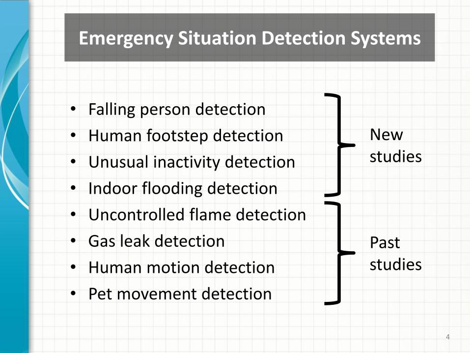
Emergency Situation Detection Systems
• Falling person detection
• Human footstep detection
• Unusual inactivity detection
• Indoor flooding detection
• Uncontrolled flame detection
• Gas leak detection
• Human motion detection
• Pet movement detection
Past studies
New studies
5
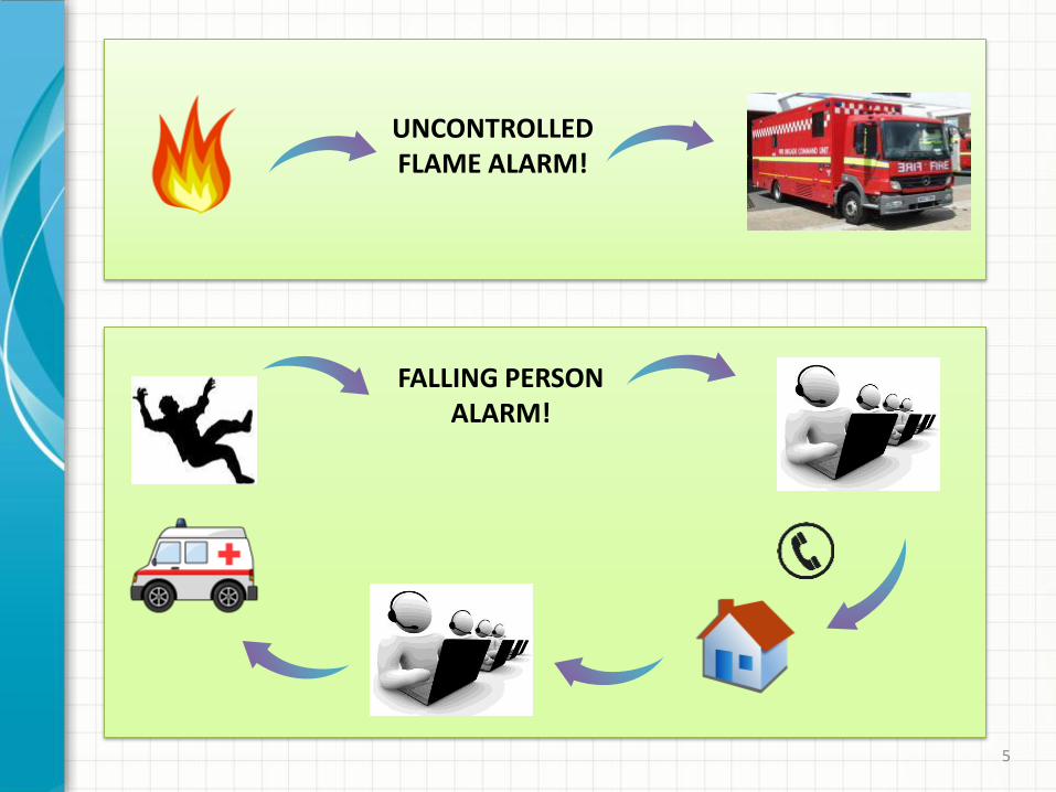
UNCONTROLLED FLAME ALARM!
FALLING PERSON ALARM!

6
• Number of the elderly people increase rapidly.
• About one-third of people over 65 falls unexpectedly [1].
• Falling is the most common cause of injury amongst seniors.
• Fall related health and injury cost is considered as billions of dollars worldwide.
• Unusual inactivity detection is also very important because of the sudden diseases like heart attacks.
[1] Hausdorff, J.M. et.al. , "Gait Variability and Fall Risk in Community-Living Older Adults: A 1-Year Prospective Study," Archives of Physical Medicine and Rehabilitation, 82(8), pp.1050–1056, 2001.
What is our motivation?

7
2007 2013
Wearable Fall Detection Systems:
Ambient Assisted Living Systems for Fall Detection:
2004 2013 Computer vision based systems
2011 2013
Kinect sensors
Wearable sensors
Literature Search and Review
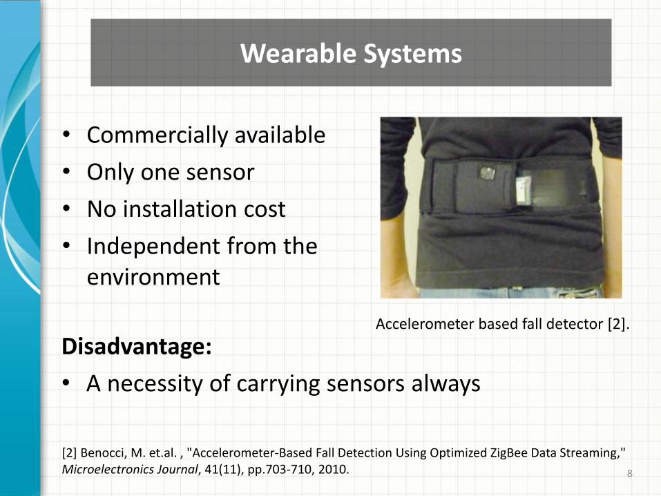
• Commercially available
• Only one sensor
• No installation cost
• Independent from the environment
8
[2] Benocci, M. et.al. , "Accelerometer-Based Fall Detection Using Optimized ZigBee Data Streaming," Microelectronics Journal, 41(11), pp.703-710, 2010.
Accelerometer based fall detector [2].
Disadvantage:
• A necessity of carrying sensors always
Wearable Systems
• Training the system for many different situations is possible.
Disadvantages:
• Privacy enemy
• High computational power of processors
• Large number of cameras to handle blind spots
• Installation cost
• High cost of the overall system
9
Computer Vision Based Systems
10
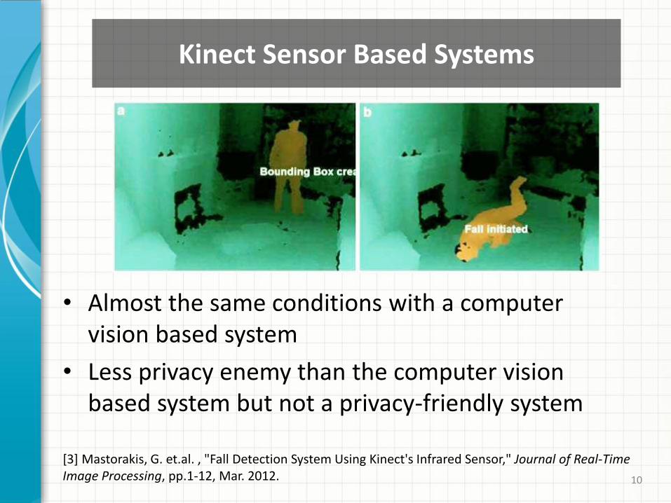
[3] Mastorakis, G. et.al. , "Fall Detection System Using Kinect's Infrared Sensor," Journal of Real-Time Image Processing, pp.1-12, Mar. 2012.
• Almost the same conditions with a computer vision based system
• Less privacy enemy than the computer vision based system but not a privacy-friendly system
Kinect Sensor Based Systems

• Privacy-friendly
• Unnoticeable system to the person
• Lower cost than camera and Kinect based systems
• Only 1-D signal processing
• No need to consider forgetfulness
Disadvantages:
• Large number of sensors
• Installation cost
11
Our Multi-Sensor Based System
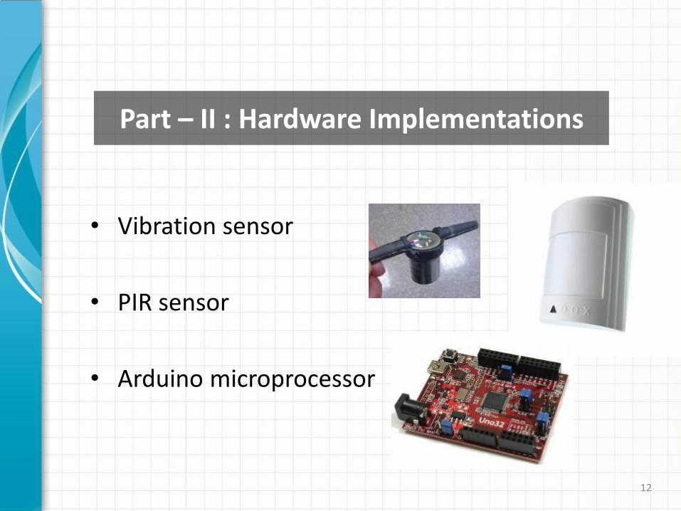
• Vibration sensor
• PIR sensor
• Arduino microprocessor
12
Part – II : Hardware Implementations
13 13
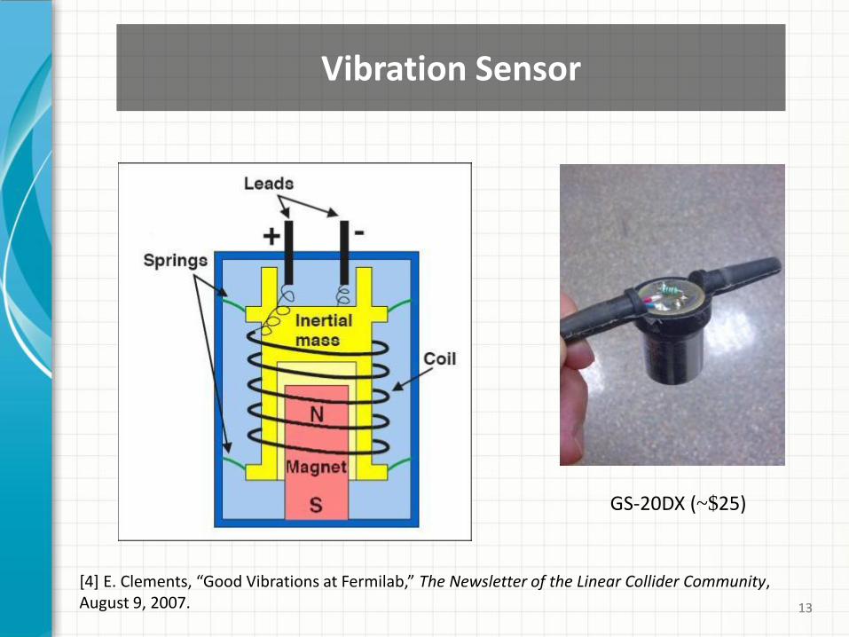
GS-20DX (~$25)
Vibration Sensor
[4] E. Clements, “Good Vibrations at Fermilab,” The Newsletter of the Linear Collider Community, August 9, 2007.
14 14
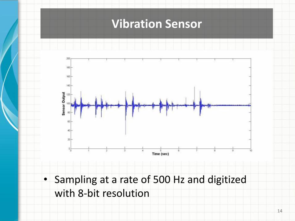
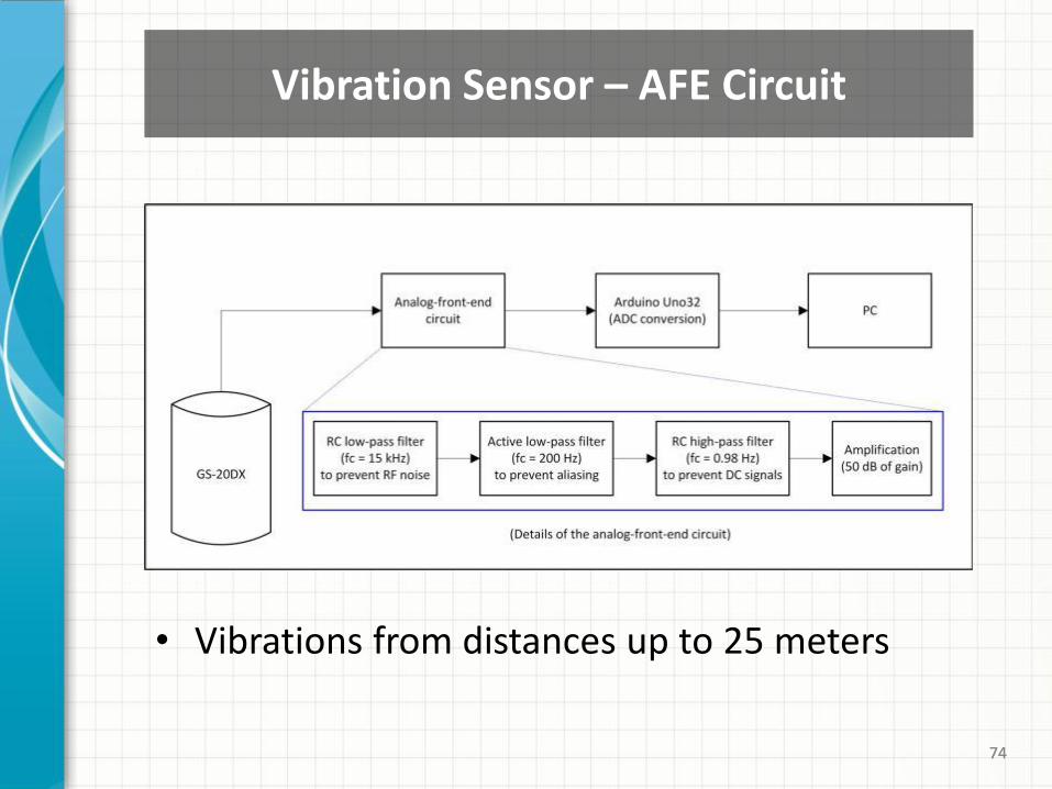
Vibration Sensor
• Sampling at a rate of 500 Hz and digitized with 8-bit resolution
15 15 15
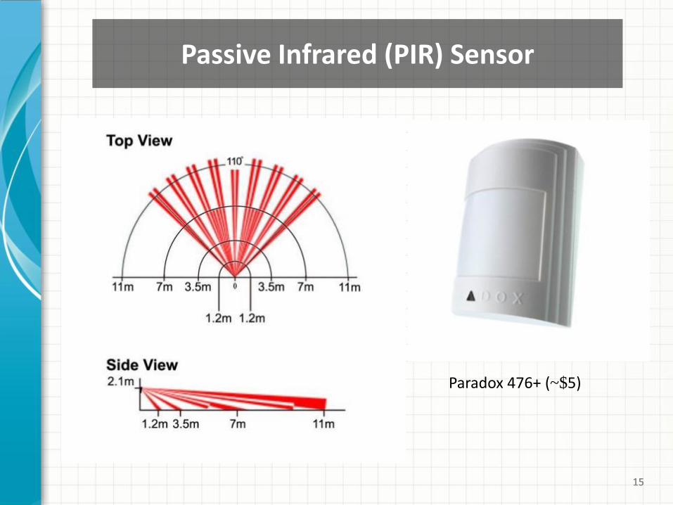
Paradox 476+ (~$5)
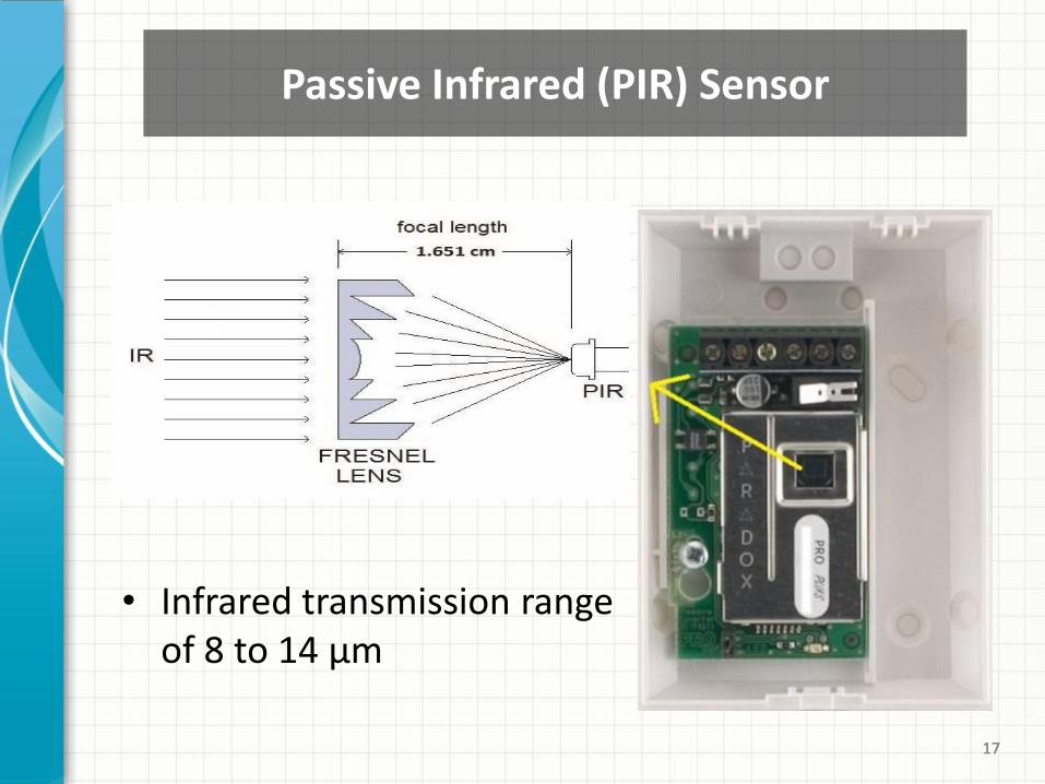
Passive Infrared (PIR) Sensor
16 16 16
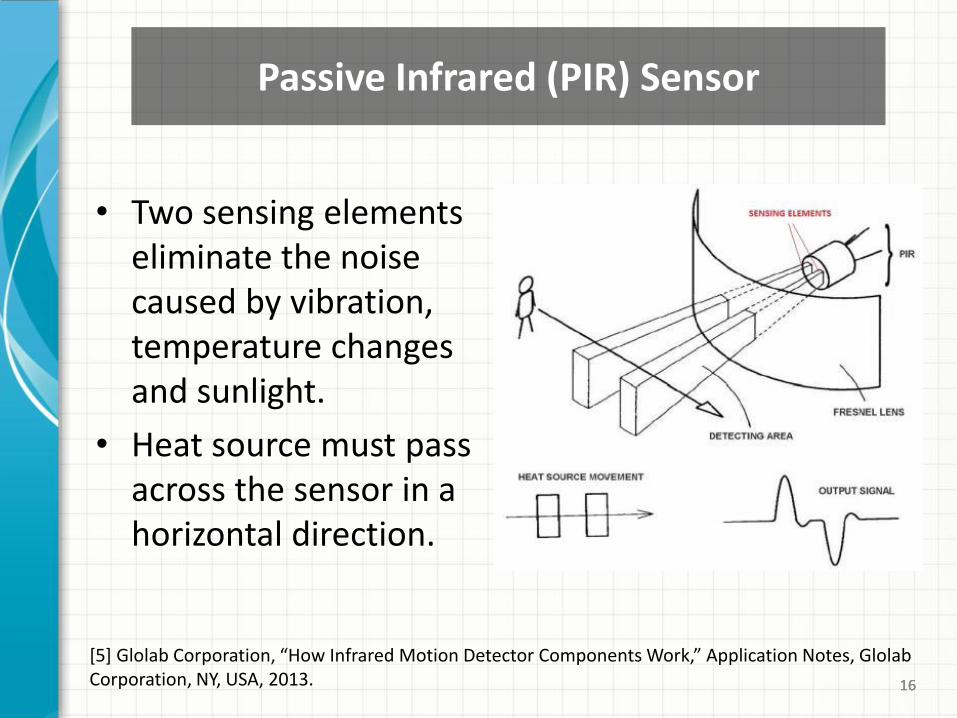
[5] Glolab Corporation, “How Infrared Motion Detector Components Work,” Application Notes, Glolab Corporation, NY, USA, 2013.
• Two sensing elements eliminate the noise caused by vibration, temperature changes and sunlight.
• Heat source must pass across the sensor in a horizontal direction.
Passive Infrared (PIR) Sensor
17 17 17
• Infrared transmission range of 8 to 14 µm
Passive Infrared (PIR) Sensor
18 18
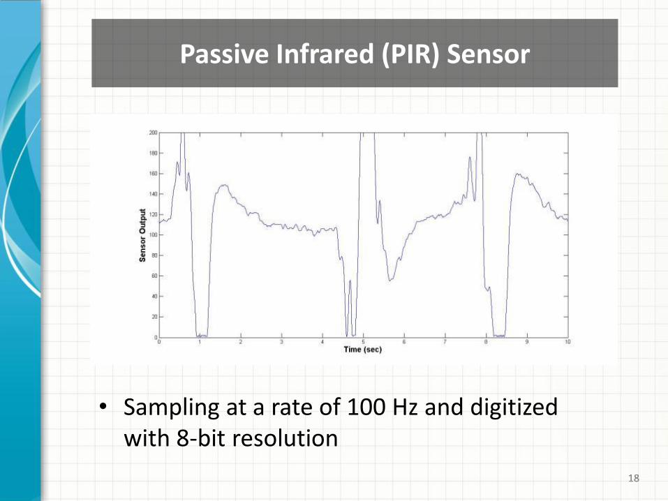
Passive Infrared (PIR) Sensor
• Sampling at a rate of 100 Hz and digitized with 8-bit resolution

19 19 19
• PIC32MX320F128 processor
• 80 Mhz 32-bit MIPS
• 128K Flash, 16K SRAM
• 42 available I/O
• 12 analog inputs
• 3.3V operating voltage
• 75mA typical operating current
chipKIT Uno32 (~$25)
Arduino Uno32 Prototyping Platform
20 20 20
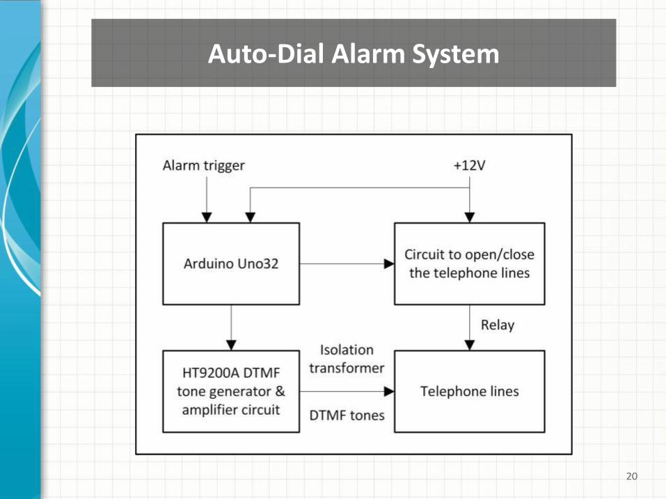
Auto-Dial Alarm System
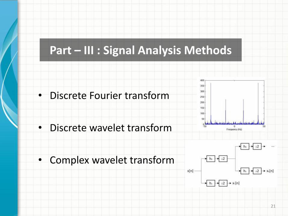
• Discrete Fourier transform
• Discrete wavelet transform
• Complex wavelet transform
21
Part – III : Signal Analysis Methods
22
• The main purpose is to extract meaningful information from the one-dimensional signals.
• Example application: Falling person detection using the vibration sensor.
• Frequency contents of the one-dimensional signals are analyzed in eight sub-bands.
• More emphasis is given to lower frequencies by assigning more sub-bands to them.
• Energies of these frequency sub-bands are employed as eight feature parameters.
Feature Extraction from 1-D Signals
23
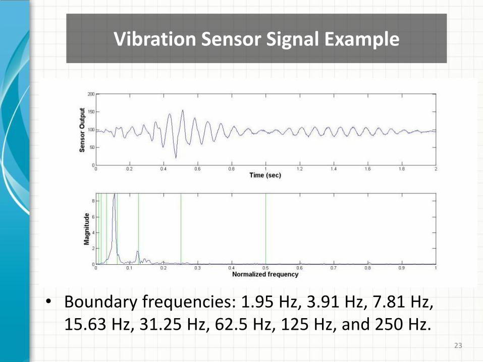
• Boundary frequencies: 1.95 Hz, 3.91 Hz, 7.81 Hz, 15.63 Hz, 31.25 Hz, 62.5 Hz, 125 Hz, and 250 Hz.
Vibration Sensor Signal Example
24
𝐺 𝑚 = 𝑋 𝑘 2
𝑘𝜖𝐵 𝑚
, 𝑚 = 1, … , 8
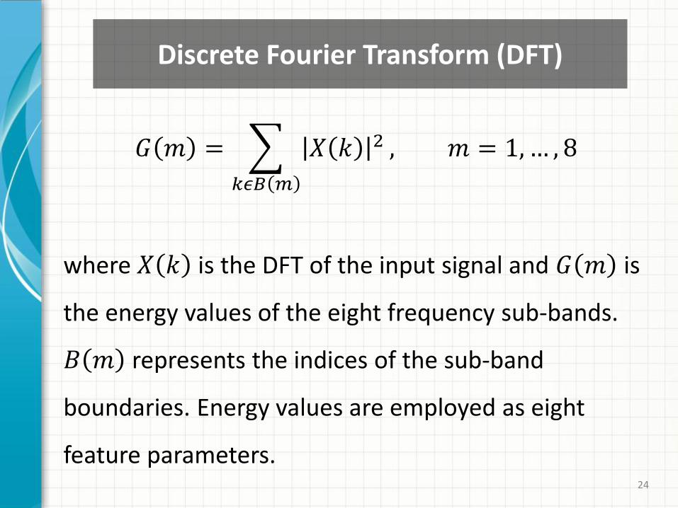
where 𝑋 𝑘 is the DFT of the input signal and 𝐺 𝑚 is
the energy values of the eight frequency sub-bands.
𝐵 𝑚 represents the indices of the sub-band
boundaries. Energy values are employed as eight
feature parameters.
Discrete Fourier Transform (DFT)
25
Mel-Frequency Cepstral Coefficients (MFCC)
𝐺 𝑚 = 𝑋 𝑘 2
𝑘𝜖𝐵 𝑚
, 𝑚 = 1, … , 8
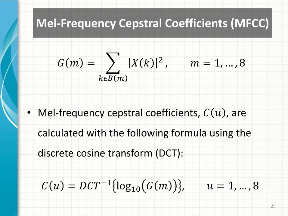
• Mel-frequency cepstral coefficients, 𝐶 𝑢 , are
calculated with the following formula using the
discrete cosine transform (DCT):
𝐶 𝑢 = 𝐷𝐶𝑇−1 log10 𝐺 𝑚 , 𝑢 = 1, … , 8
26
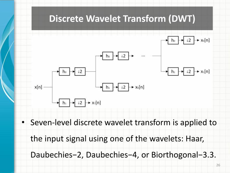
• Seven-level discrete wavelet transform is applied to
the input signal using one of the wavelets: Haar,
Daubechies−2, Daubechies−4, or Biorthogonal−3.3.
Discrete Wavelet Transform (DWT)
27
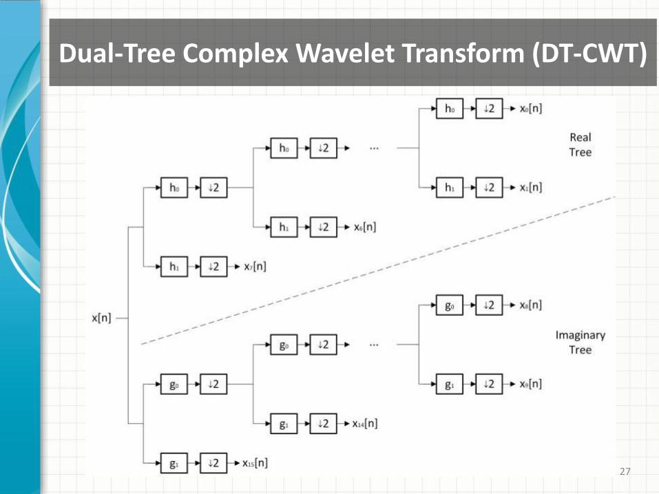
Dual-Tree Complex Wavelet Transform (DT-CWT)
28
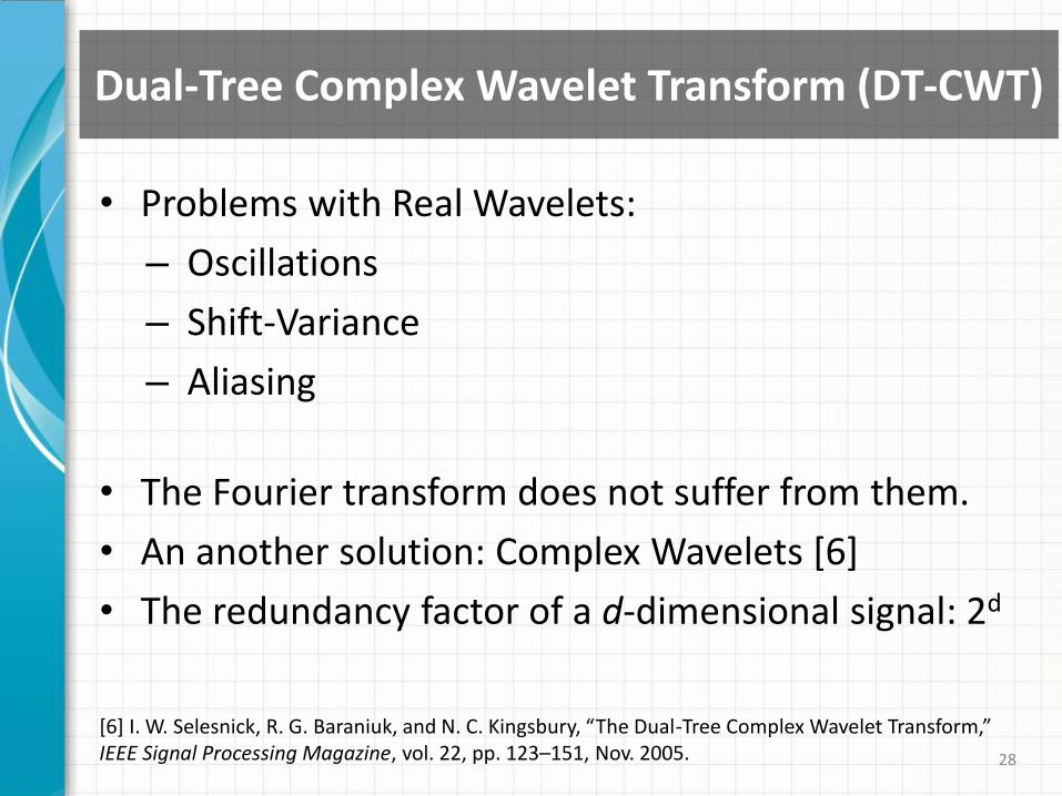
Dual-Tree Complex Wavelet Transform (DT-CWT)
• Problems with Real Wavelets:
– Oscillations
– Shift-Variance
– Aliasing
• The Fourier transform does not suffer from them.
• An another solution: Complex Wavelets [6]
• The redundancy factor of a d-dimensional signal: 2d
[6] I. W. Selesnick, R. G. Baraniuk, and N. C. Kingsbury, “The Dual-Tree Complex Wavelet Transform,” IEEE Signal Processing Magazine, vol. 22, pp. 123–151, Nov. 2005.
29
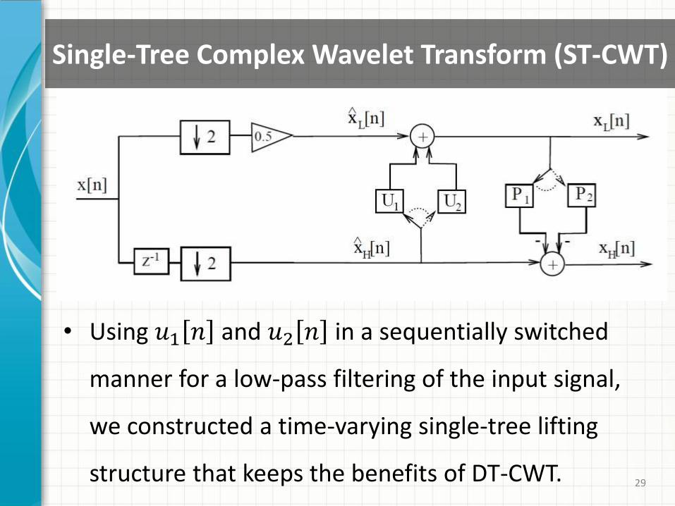
• Using 𝑢1 𝑛 and 𝑢2 𝑛 in a sequentially switched
manner for a low-pass filtering of the input signal,
we constructed a time-varying single-tree lifting
structure that keeps the benefits of DT-CWT.
Single-Tree Complex Wavelet Transform (ST-CWT)
30
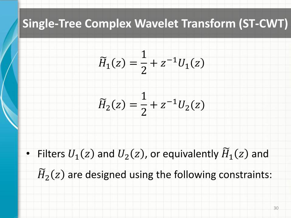
Single-Tree Complex Wavelet Transform (ST-CWT)
𝐻 1 𝑧 =1
2+ 𝑧−1𝑈1 𝑧
𝐻 2 𝑧 =1
2+ 𝑧−1𝑈2(𝑧)
• Filters 𝑈1 𝑧 and 𝑈2 𝑧 , or equivalently 𝐻 1 𝑧 and
𝐻 2 𝑧 are designed using the following constraints:
31
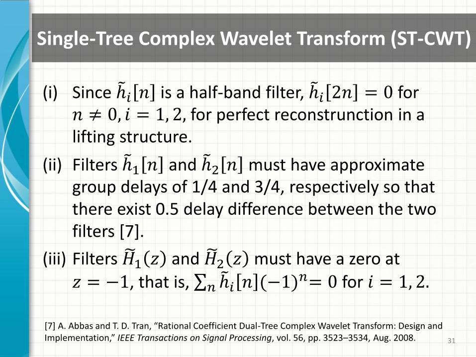
Single-Tree Complex Wavelet Transform (ST-CWT)
(i) Since ℎ 𝑖 𝑛 is a half-band filter, ℎ 𝑖 2𝑛 = 0 for 𝑛 ≠ 0, 𝑖 = 1, 2, for perfect reconstrunction in a lifting structure.
(ii) Filters ℎ 1 𝑛 and ℎ 2 𝑛 must have approximate group delays of 1/4 and 3/4, respectively so that there exist 0.5 delay difference between the two filters [7].
(iii) Filters 𝐻 1 𝑧 and 𝐻 2 𝑧 must have a zero at
𝑧 = −1, that is, ℎ 𝑖 𝑛 (−1)𝑛= 0𝑛 for 𝑖 = 1, 2.
[7] A. Abbas and T. D. Tran, “Rational Coefficient Dual-Tree Complex Wavelet Transform: Design and Implementation,” IEEE Transactions on Signal Processing, vol. 56, pp. 3523–3534, Aug. 2008.
32
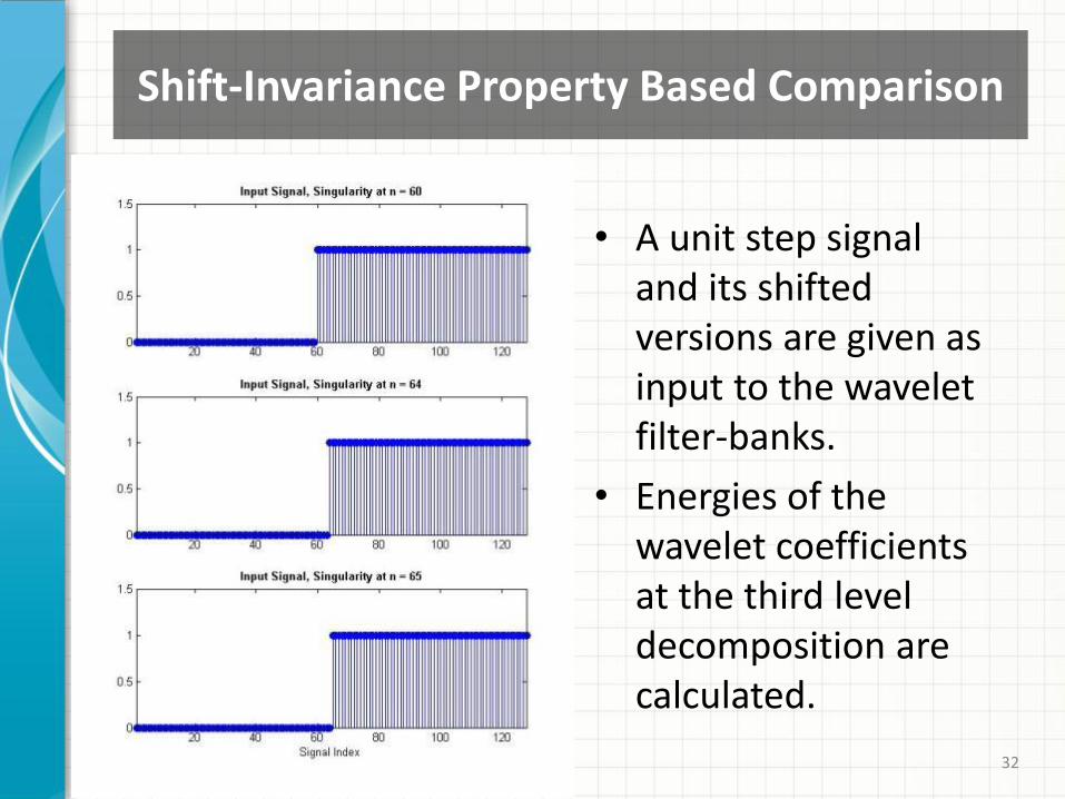
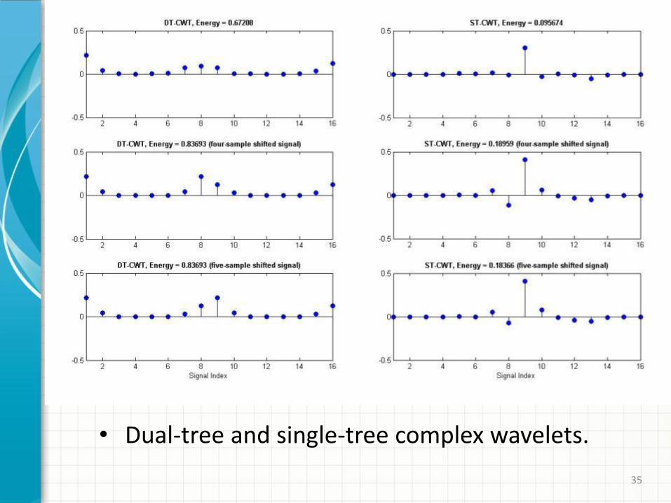
Shift-Invariance Property Based Comparison
• A unit step signal and its shifted versions are given as input to the wavelet filter-banks.
• Energies of the wavelet coefficients at the third level decomposition are calculated.

33
• Haar and Daubechies-2 wavelet filter-banks.
34
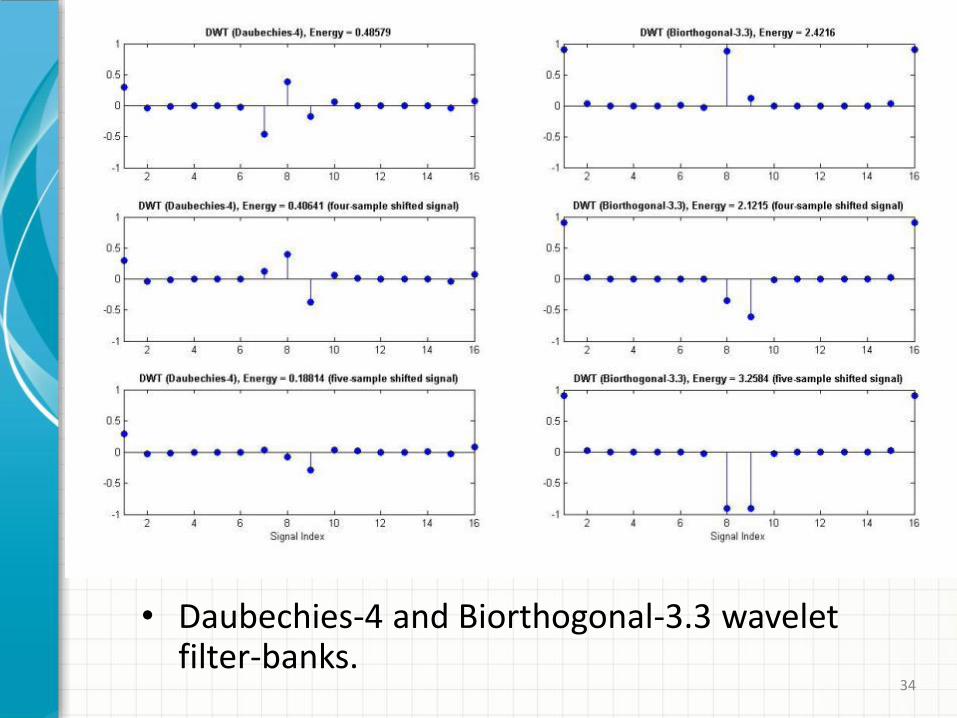
• Daubechies-4 and Biorthogonal-3.3 wavelet filter-banks.
35
• Dual-tree and single-tree complex wavelets.
36
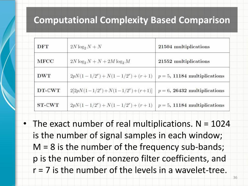
• The exact number of real multiplications. N = 1024 is the number of signal samples in each window; M = 8 is the number of the frequency sub-bands; p is the number of nonzero filter coefficients, and r = 7 is the number of the levels in a wavelet-tree.
Computational Complexity Based Comparison
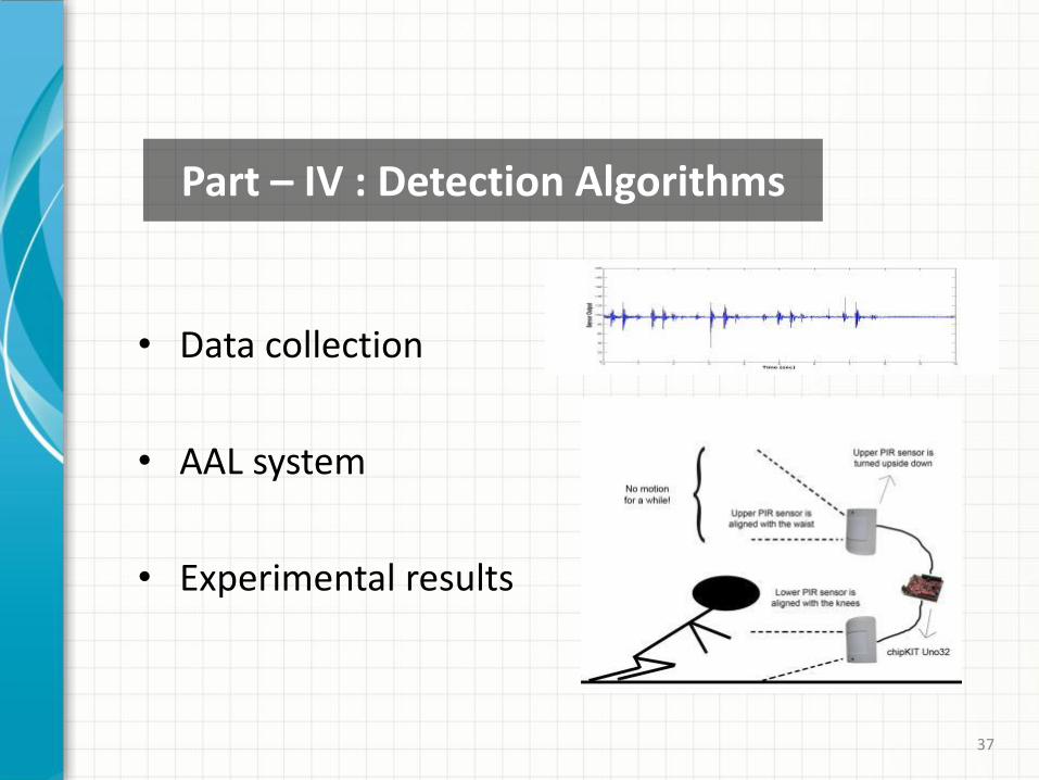
• Data collection
• AAL system
• Experimental results
37
Part – IV : Detection Algorithms
38 38 38
Data Collection
• Vibration sensor signal records are taken in different experimental environments:
– Third floor of a new building (concrete floor),
– Second floor of an old building (hardwood floor),
– Fourth floor of a new building (hardwood floor).
• Vibration sensor signals may contain various frequency components depending on
– the architecture of the building,
– running machines in the building,
– the person living in the house.
39
Datasets
• Five different datasets are employed to train and test the detection systems:
– Motion-inactivity dataset -> One PIR sensor
– Footstep dataset -> One vibration sensor
– Falling dataset-1 -> One vibration sensor
– Falling dataset-2 -> One vibration sensor, two PIR sensors
– Flooding dataset -> One vibration sensor
• Two-second-long signal windows are used in the detection algorithms.
40
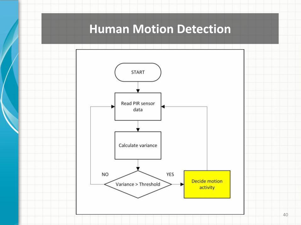
Human Motion Detection
41
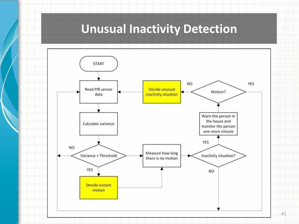
Unusual Inactivity Detection
42
Experimental Results
• The time period is taken 10 minutes to decide
the unusual inactivity situation in the tests.
• 20-hours unusual inactivity record is divided
into 10-minutes parts and totally 120 parts are
tested.
• 100% of the 120 parts are classified correctly.
43
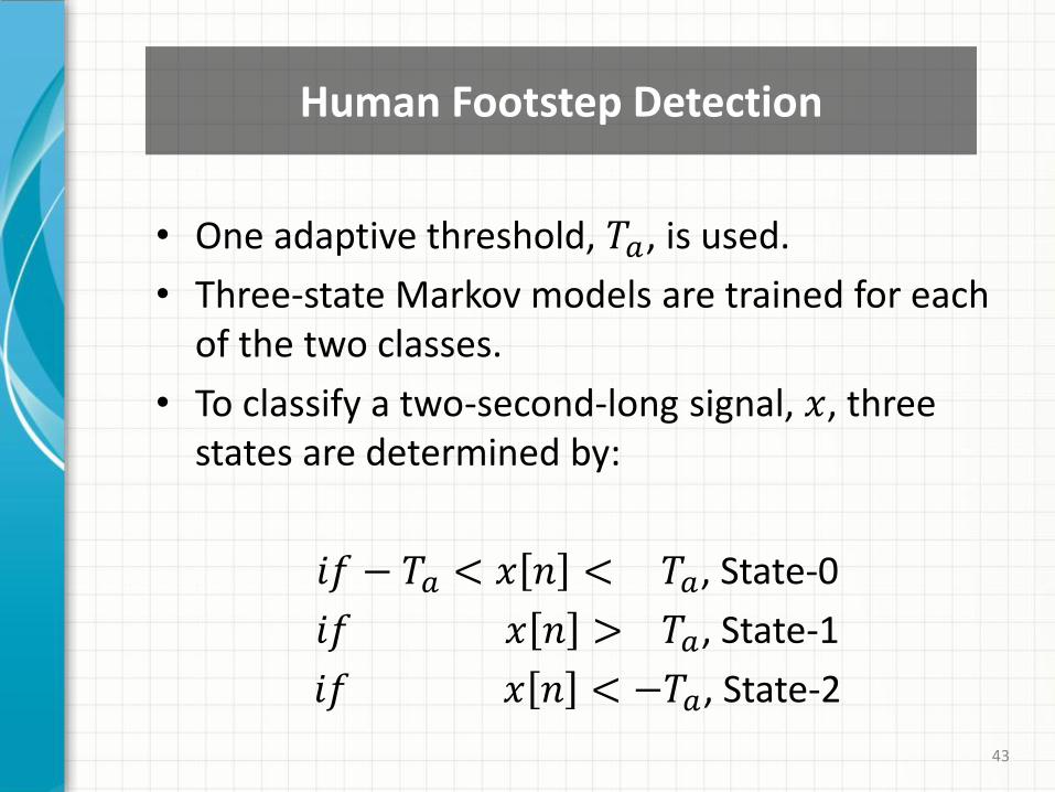
Human Footstep Detection
• One adaptive threshold, 𝑇𝑎, is used.
• Three-state Markov models are trained for each of the two classes.
• To classify a two-second-long signal, 𝑥, three states are determined by:
𝑖𝑓 − 𝑇𝑎 < 𝑥 𝑛 < 𝑇𝑎, State-0
𝑖𝑓 𝑥 𝑛 > 𝑇𝑎, State-1
𝑖𝑓 𝑥 𝑛 < −𝑇𝑎, State-2
44
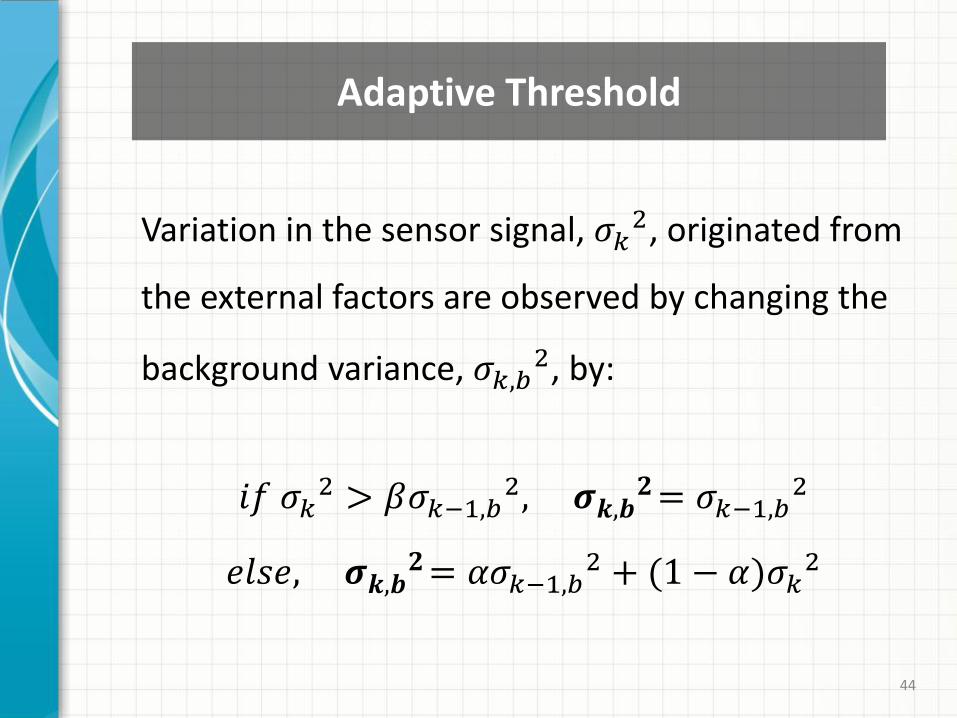
Adaptive Threshold
Variation in the sensor signal, 𝜎𝑘2, originated from
the external factors are observed by changing the
background variance, 𝜎𝑘,𝑏2, by:
𝑖𝑓 𝜎𝑘2 > 𝛽𝜎𝑘−1,𝑏
2, 𝝈𝒌,𝒃𝟐= 𝜎𝑘−1,𝑏
2
𝑒𝑙𝑠𝑒, 𝝈𝒌,𝒃𝟐= 𝛼𝜎𝑘−1,𝑏
2 + (1 − 𝛼)𝜎𝑘2
45
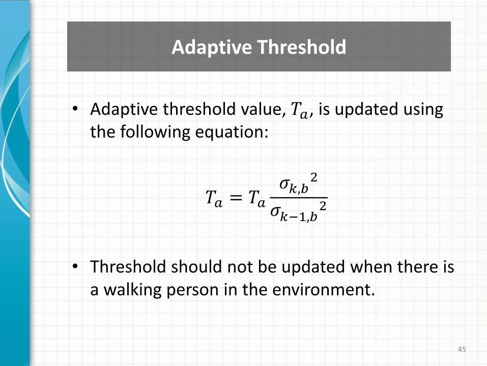
Adaptive Threshold
• Adaptive threshold value, 𝑇𝑎, is updated using the following equation:
𝑇𝑎 = 𝑇𝑎
𝜎𝑘,𝑏2
𝜎𝑘−1,𝑏2
• Threshold should not be updated when there is a walking person in the environment.
46
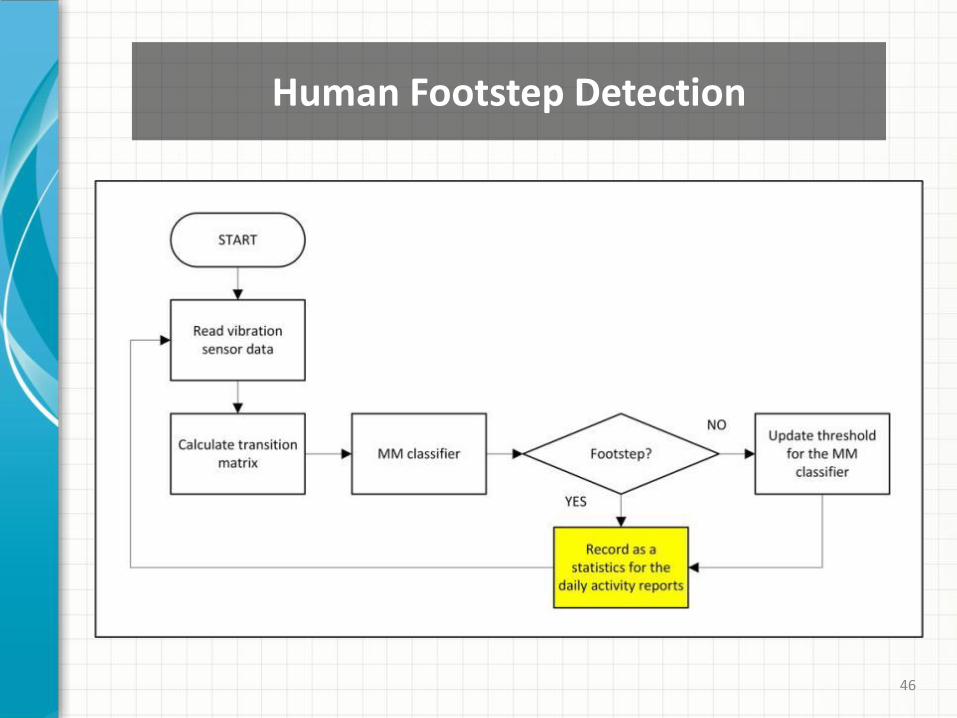
Human Footstep Detection
47
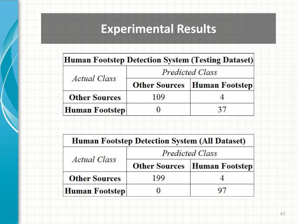
Experimental Results
48
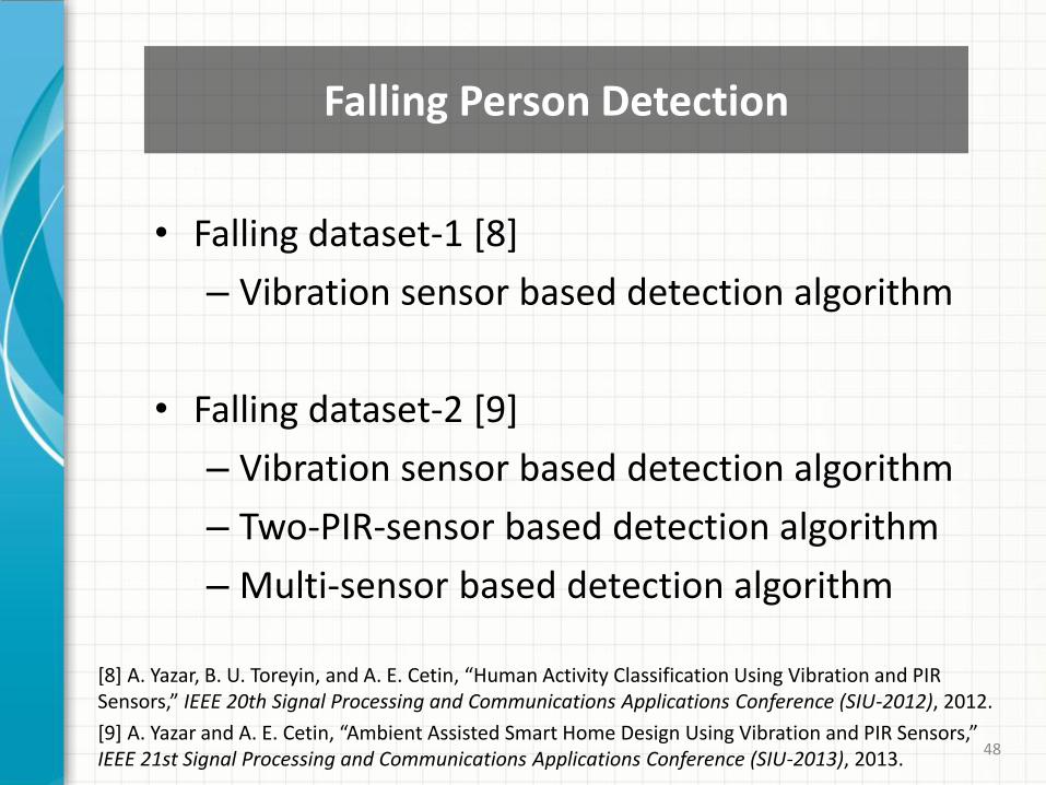
Falling Person Detection
• Falling dataset-1 [8]
– Vibration sensor based detection algorithm
• Falling dataset-2 [9]
– Vibration sensor based detection algorithm
– Two-PIR-sensor based detection algorithm
– Multi-sensor based detection algorithm
[8] A. Yazar, B. U. Toreyin, and A. E. Cetin, “Human Activity Classification Using Vibration and PIR Sensors,” IEEE 20th Signal Processing and Communications Applications Conference (SIU-2012), 2012.
[9] A. Yazar and A. E. Cetin, “Ambient Assisted Smart Home Design Using Vibration and PIR Sensors,” IEEE 21st Signal Processing and Communications Applications Conference (SIU-2013), 2013.
49 49 49
Fall Detection Using Vibration Sensor
• A typical instant falling event generally lasts about two seconds.
• Frequency content of the vibration sensor signal is analyzed in eight sub-bands.
• Energies of these frequency sub-bands are employed as eight feature parameters.
• DFT, MFCC, DWT, DT-CWT, and ST-CWT signal analysis methods compared to each other.
• SVM classifiers are trained and used.
50 50 50
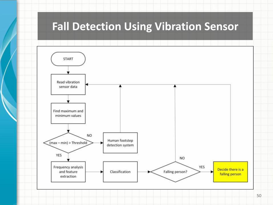
Fall Detection Using Vibration Sensor
51
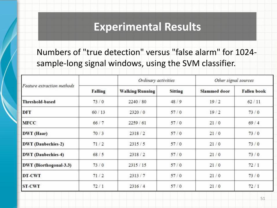
Experimental Results
Numbers of "true detection" versus "false alarm" for 1024-sample-long signal windows, using the SVM classifier.
52
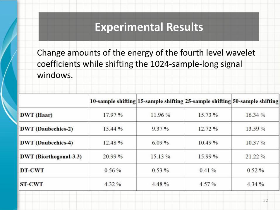
Experimental Results
Change amounts of the energy of the fourth level wavelet coefficients while shifting the 1024-sample-long signal windows.
53 53 53
• Falling person can be detected only in the falling instant using the vibration sensor.
• There is no chance to analyze the falling event if a sufficient vibration is not sensed on the floor (miss-detection).
• Some of the slow fallings may not be detected using vibration sensor (miss-detection).
• Vibration sensor based system can not sense the activities after falling (e.g. standing up).
Fall Detection Using Vibration Sensor
54 54 54
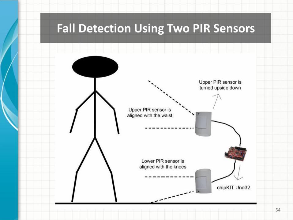
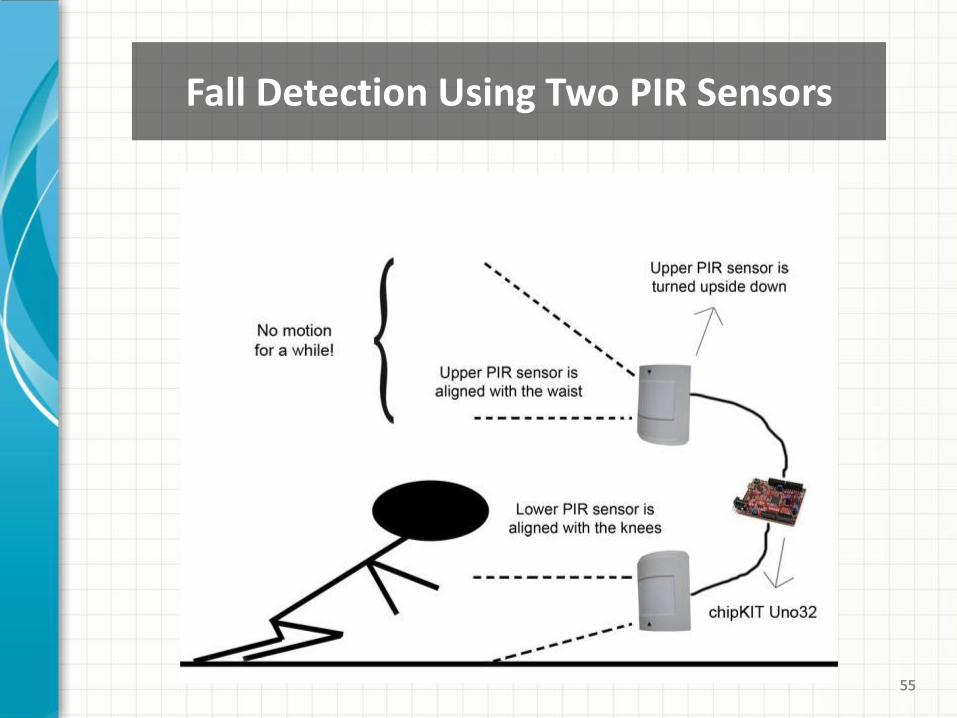
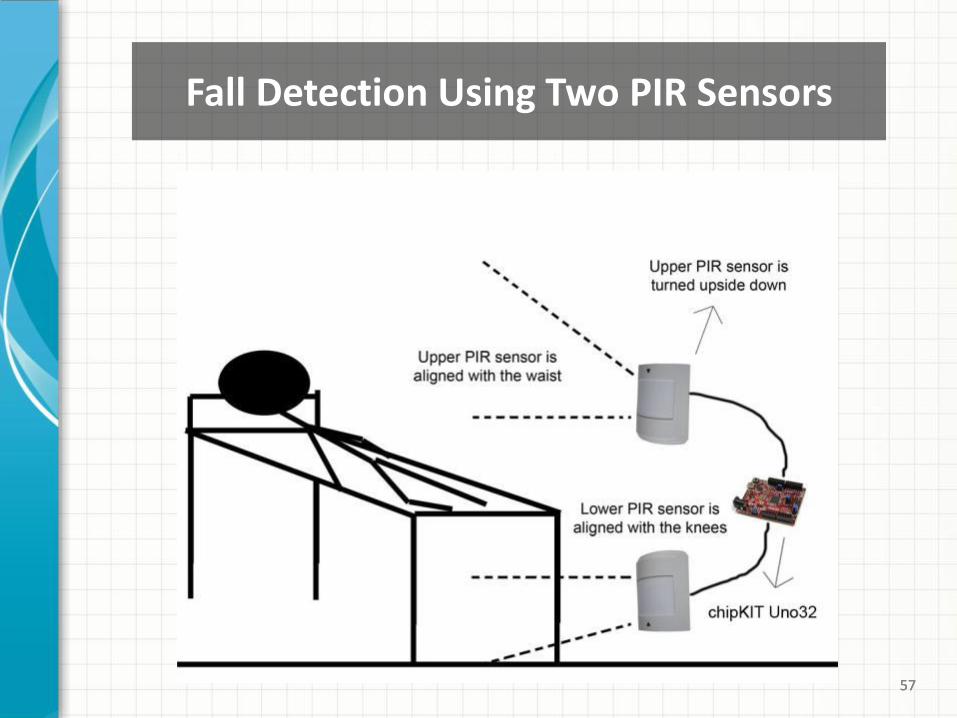
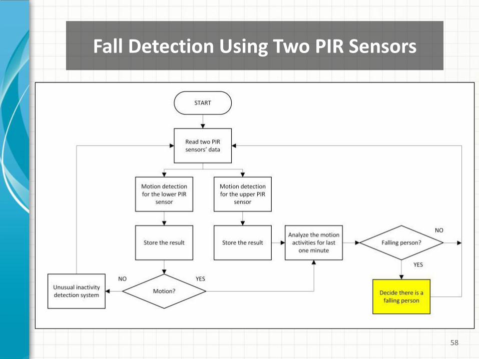
Fall Detection Using Two PIR Sensors
55 55 55
Fall Detection Using Two PIR Sensors

56 56 56
Fall Detection Using Two PIR Sensors
57 57 57
Fall Detection Using Two PIR Sensors
58 58 58
Fall Detection Using Two PIR Sensors
59 59 59
• Advantages:
– Slow fallings can be detected.
– Sensor signals can be analyzed before and after of the falling event.
– The system does not affected by the person or the environment.
• Disadvantage:
– This system can not detect instant falling events which are ended up with a fainting.
Fall Detection Using Two PIR Sensors
60 60 60
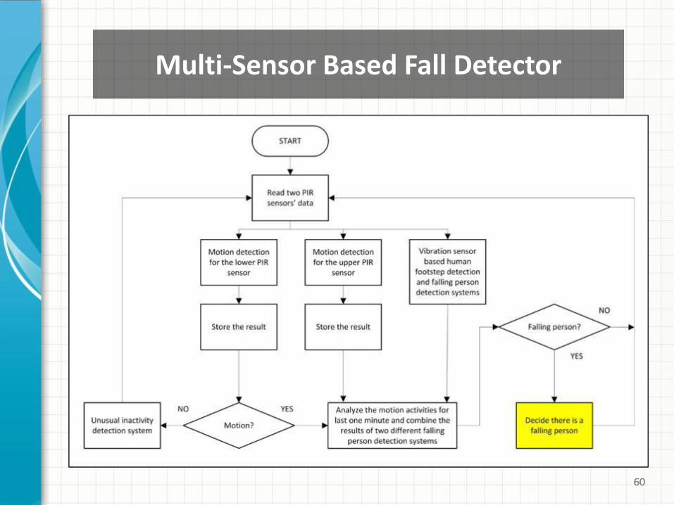
Multi-Sensor Based Fall Detector
61
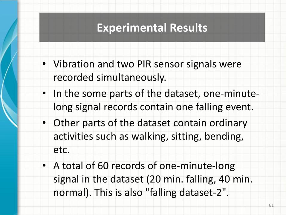
Experimental Results
• Vibration and two PIR sensor signals were recorded simultaneously.
• In the some parts of the dataset, one-minute-long signal records contain one falling event.
• Other parts of the dataset contain ordinary activities such as walking, sitting, bending, etc.
• A total of 60 records of one-minute-long signal in the dataset (20 min. falling, 40 min. normal). This is also "falling dataset-2".
62 62 62
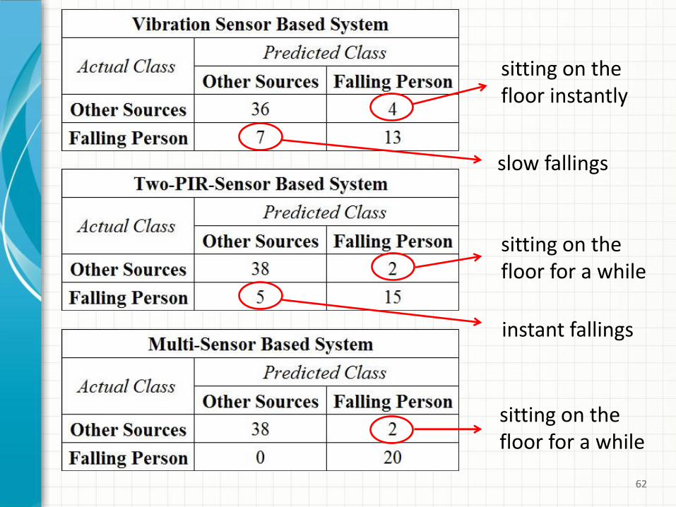
slow fallings
sitting on the floor instantly
sitting on the floor for a while
instant fallings
sitting on the floor for a while
63
Indoor Flooding Detection
• A remarkable variation does not happened for the PIR sensor signal while the water is running from the tap.
• The vibration sensor based system is developed to benefit from the water dropping sourced vibrations on the floor.
• An adaptive-threshold based method is employed.
• A low-cost simple conductivity based circuit is a better solution to detect indoor flooding.
64 64 64
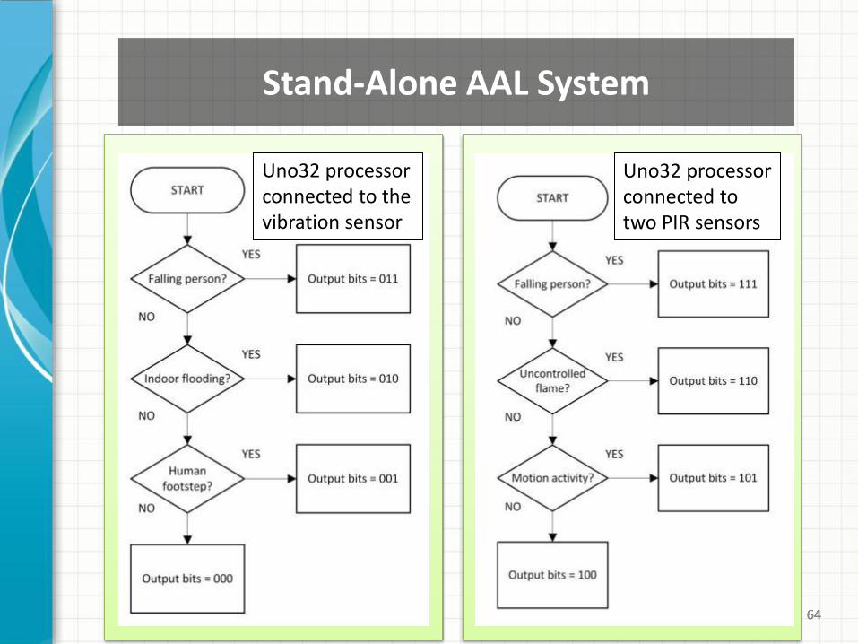
Stand-Alone AAL System
Uno32 processor connected to the vibration sensor
Uno32 processor connected to two PIR sensors
65 65 65
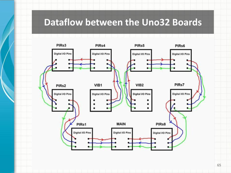
Dataflow between the Uno32 Boards
66 66 66
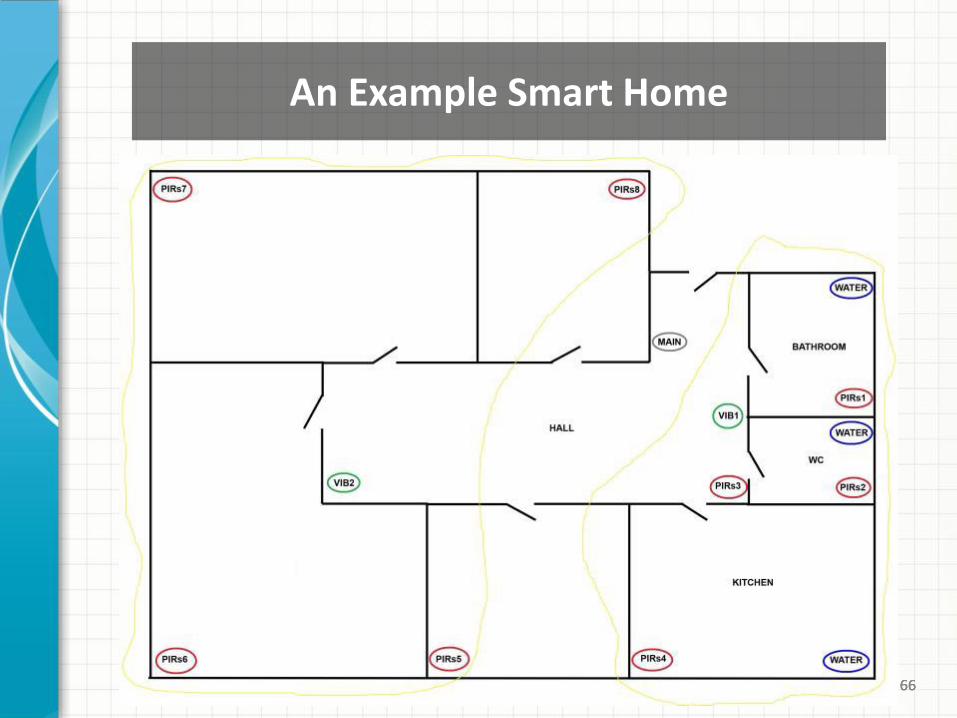
An Example Smart Home

• What we did?
• What is our contribution?
• What will we do?
67
Part – V : Conclusion and Future Work
68
Conclusion
• Ambient Assisted Living (AAL) system is developed for the purpose of achievement a saleable product.
• The resulting AAL system is a low-cost and privacy-friendly system.
• Vibration and PIR sensor signals are analyzed and some theoretical methods are studied on these signals.
• All detection algorithms are implemented using embedded microprocessors.
69
Contribution
• Design of a real single-tree lifting-based wavelet transform that possesses complex wavelet-like characteristics.
• Human footstep detection is achieved by using the adaptive-threshold based Markov model classifier.
• Three separate falling person detection algorithms are introduced.
• The stand-alone AAL system using the vibration and two PIR sensors is developed.
70 70 70
• Sensitive human footstep detection using the vibration sensor
• Various adaptive systems for the vibration sensor
• Larger dataset, different human activities and environments
• Power consumption calculations for the overall AAL system
• Converting the existing hard-wired networking system to a wireless one
Future Works - 1
71 71 71
• Solution for the false alarm sources such as sitting on the floor for a while
• Generalization of the falling person detection system to handle with different disabilities (paralyzed people, having wheelchair, etc.).
• Analyzing the motion activities of sleeping people to sense a possible problem earlier
• Integration of the gas leak detection and pet detection systems to the overall AAL system
Future Works - 2
72 72 72
Thank you for listening…
Ahmet Yazar [email protected]
Prof. Dr. A. Enis Çetin [email protected]
http://signal.ee.bilkent.edu.tr

73
Extra Slides
74 74
Vibration Sensor – AFE Circuit
• Vibrations from distances up to 25 meters
75
0 𝑓𝑠
256,
𝑓𝑠
256
𝑓𝑠
128,
𝑓𝑠
128 𝑓𝑠
64,
𝑓𝑠
64 𝑓𝑠
32,
𝑓𝑠
32 𝑓𝑠
16,
𝑓𝑠
16 𝑓𝑠
8,
𝑓𝑠
8 𝑓𝑠
4,
𝑓𝑠
4 𝑓𝑠
2
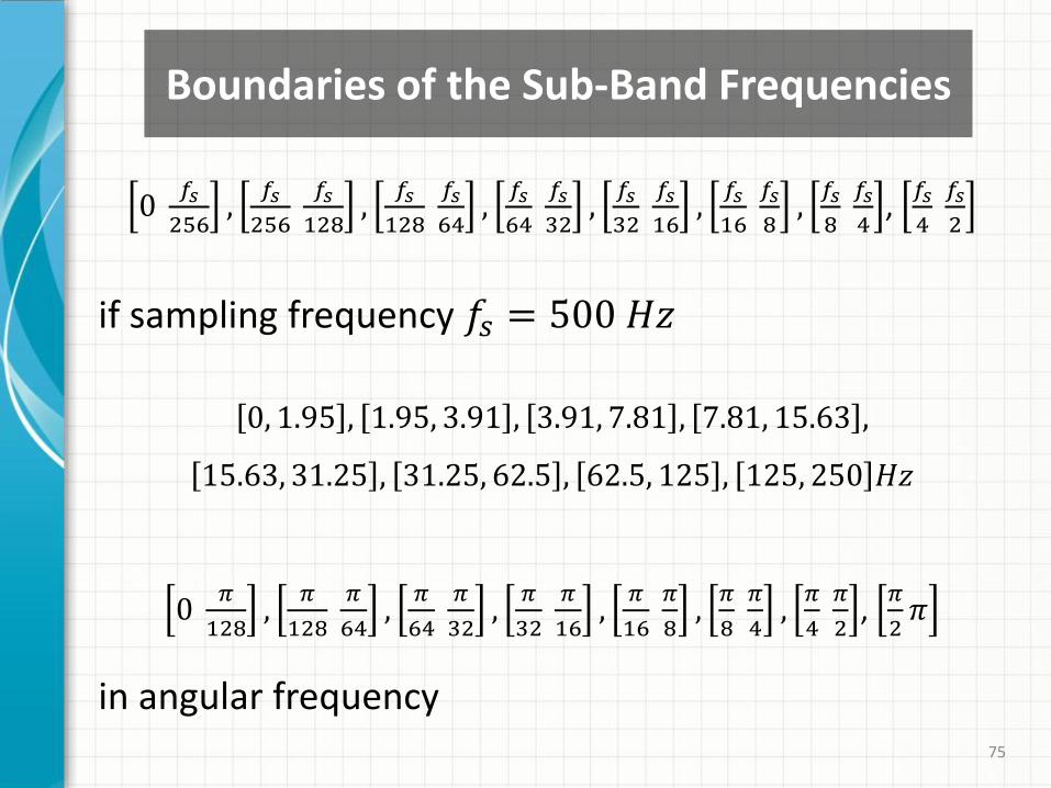
if sampling frequency 𝑓𝑠 = 500 𝐻𝑧
0, 1.95 , 1.95, 3.91 , 3.91, 7.81 , 7.81, 15.63 ,
15.63, 31.25 , 31.25, 62.5 , 62.5, 125 , 125, 250 𝐻𝑧
0 𝜋
128,
𝜋
128
𝜋
64,
𝜋
64
𝜋
32,
𝜋
32
𝜋
16,
𝜋
16 𝜋
8,
𝜋
8 𝜋
4,
𝜋
4 𝜋
2,
𝜋
2𝜋
in angular frequency
Boundaries of the Sub-Band Frequencies
76
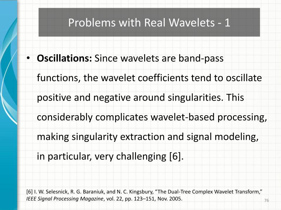
• Oscillations: Since wavelets are band-pass
functions, the wavelet coefficients tend to oscillate
positive and negative around singularities. This
considerably complicates wavelet-based processing,
making singularity extraction and signal modeling,
in particular, very challenging [6].
Problems with Real Wavelets - 1
[6] I. W. Selesnick, R. G. Baraniuk, and N. C. Kingsbury, “The Dual-Tree Complex Wavelet Transform,” IEEE Signal Processing Magazine, vol. 22, pp. 123–151, Nov. 2005.
77
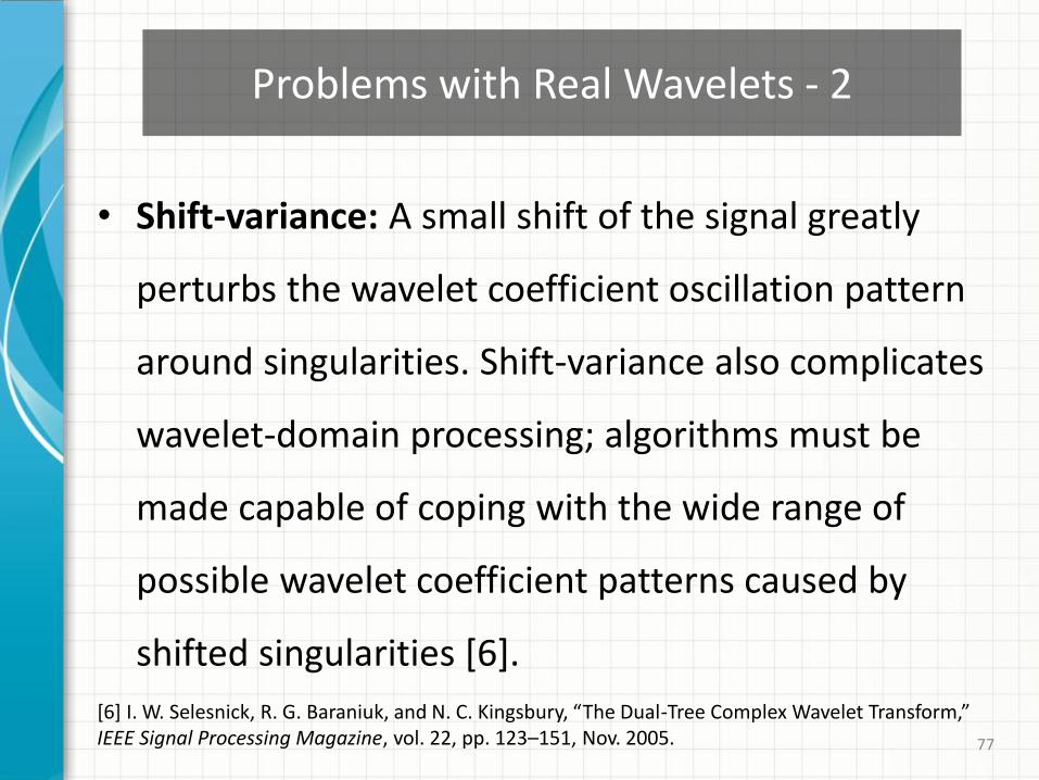
• Shift-variance: A small shift of the signal greatly
perturbs the wavelet coefficient oscillation pattern
around singularities. Shift-variance also complicates
wavelet-domain processing; algorithms must be
made capable of coping with the wide range of
possible wavelet coefficient patterns caused by
shifted singularities [6].
Problems with Real Wavelets - 2
[6] I. W. Selesnick, R. G. Baraniuk, and N. C. Kingsbury, “The Dual-Tree Complex Wavelet Transform,” IEEE Signal Processing Magazine, vol. 22, pp. 123–151, Nov. 2005.
78
• Aliasing: The wide spacing of the wavelet coefficient
samples, or equivalently, the fact that the wavelet
coefficients are computed via iterated discrete-time
downsampling operations interspersed with
nonideal low-pass and high-pass filters, results in
substantial aliasing [6].
Problems with Real Wavelets - 3
[6] I. W. Selesnick, R. G. Baraniuk, and N. C. Kingsbury, “The Dual-Tree Complex Wavelet Transform,” IEEE Signal Processing Magazine, vol. 22, pp. 123–151, Nov. 2005.
79
• Lack of directionality: While Fourier sinusoids in
higher dimensions correspond to highly directional
plane waves, the standard tensor product
construction of M-D wavelets produces a
checkerboard pattern that is simultaneously
oriented along several directions [6].
Problems with Real Wavelets - 4
[6] I. W. Selesnick, R. G. Baraniuk, and N. C. Kingsbury, “The Dual-Tree Complex Wavelet Transform,” IEEE Signal Processing Magazine, vol. 22, pp. 123–151, Nov. 2005.
80
Analyticity
• A function 𝑓𝑎 ∈ 𝐿2 𝑅 is said to be analytic if its
Fourier transform is zero for negative frequencies:
𝑓 𝑎 𝑤 = 0 if 𝑤 < 0
• An analytic function is necessarily complex but is
entirely characterized by its real part.
[10] S. Mallat, A Wavelet Tour of Signal Processing, 3rd Edition: The Sparse Way, Academic Press, Dec. 2008.
81
ψ𝑐 𝑡 = ψℎ 𝑡 + jψ𝑔
𝑡
where ψℎ 𝑡 and ψ𝑔 𝑡 denote the wavelet functions
of real and imaginary trees, respectively.
• If ψ𝑐 𝑡 is approximately analytic, the resulting
transform can possess shift-invariance and lack of
aliasing properties just like the Fourier transform.
Analytic Complex Wavelet - 1
82
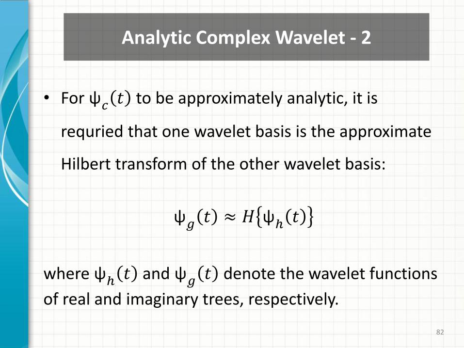
• For ψ𝑐 𝑡 to be approximately analytic, it is
requried that one wavelet basis is the approximate
Hilbert transform of the other wavelet basis:
ψ𝑔 𝑡 ≈ 𝐻 ψℎ 𝑡
where ψℎ 𝑡 and ψ𝑔 𝑡 denote the wavelet functions
of real and imaginary trees, respectively.
Analytic Complex Wavelet - 2
83
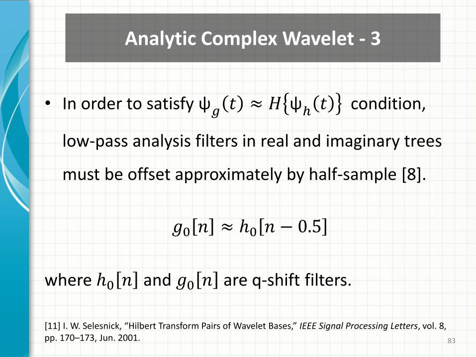
• In order to satisfy ψ𝑔 𝑡 ≈ 𝐻 ψℎ 𝑡 condition,
low-pass analysis filters in real and imaginary trees
must be offset approximately by half-sample [8].
𝑔0 𝑛 ≈ ℎ0 𝑛 − 0.5
where ℎ0 𝑛 and 𝑔0 𝑛 are q-shift filters.
Analytic Complex Wavelet - 3
[11] I. W. Selesnick, “Hilbert Transform Pairs of Wavelet Bases,” IEEE Signal Processing Letters, vol. 8, pp. 170–173, Jun. 2001.
84
• The first stage of the dual-tree filter banks should
be different from the other stages. The half-sample
delay condition shouldn’t be used for the first stage.
For the first stage, it is necessary only to translate
one set of filters by one-sample to the other and
any set of perfect reconstruction filter can be used.
Analytic Complex Wavelet - 4
[6] I. W. Selesnick, R. G. Baraniuk, and N. C. Kingsbury, “The Dual-Tree Complex Wavelet Transform,” IEEE Signal Processing Magazine, vol. 22, pp. 123–151, Nov. 2005.
85
• The key properties required for the q-shift (quarter
sample shift orthogonal) filters are that they should
provide a group delay of either 1/4 or 3/4 of a
sample period, while also satisfying the usual 2-
band filter-bank constraints of no aliasing and
perfect reconstruction [7].
Q-Shift Complex Wavelets - 1
[7] A. Abbas and T. D. Tran, “Rational Coefficient Dual-Tree Complex Wavelet Transform: Design and Implementation,” IEEE Transactions on Signal Processing, vol. 56, pp. 3523–3534, Aug. 2008.
86
• Satisfying linear-phase property of ℎ0 𝑛 is achieved by
𝑔0 𝑛 = ℎ0 𝑁 − 1 − 𝑛
where N (even) is the length of ℎ0 𝑛 .
• In q-shift method the imaginary part of the complex wavelet is a time-reversed of the real part.
Q-Shift Complex Wavelets - 2
[7] A. Abbas and T. D. Tran, “Rational Coefficient Dual-Tree Complex Wavelet Transform: Design and Implementation,” IEEE Transactions on Signal Processing, vol. 56, pp. 3523–3534, Aug. 2008.
87
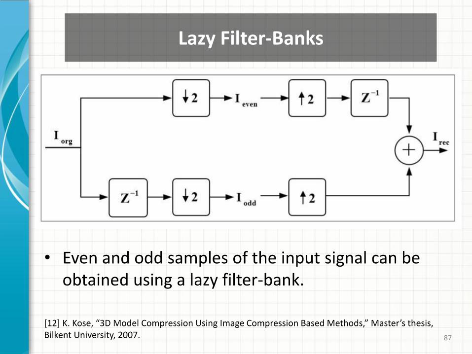
• Even and odd samples of the input signal can be obtained using a lazy filter-bank.
[12] K. Kose, “3D Model Compression Using Image Compression Based Methods,” Master’s thesis, Bilkent University, 2007.
Lazy Filter-Banks
88
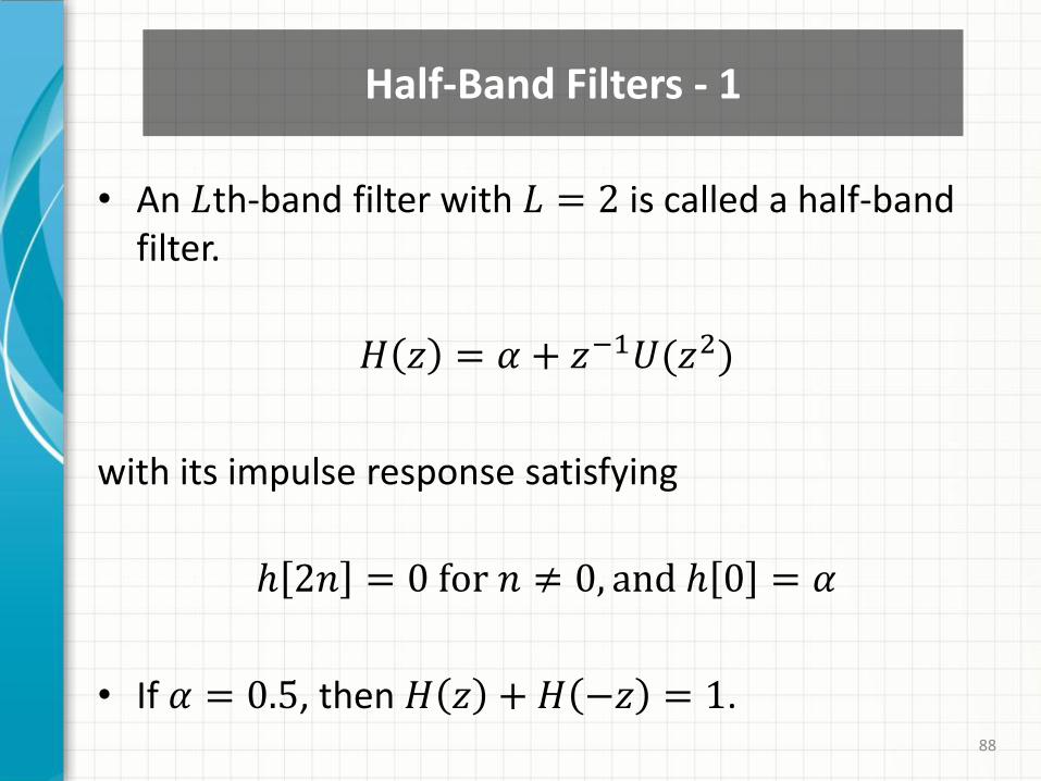
• An 𝐿th-band filter with 𝐿 = 2 is called a half-band filter.
𝐻 𝑧 = 𝛼 + 𝑧−1𝑈(𝑧2)
with its impulse response satisfying
ℎ 2𝑛 = 0 for 𝑛 ≠ 0, and ℎ 0 = 𝛼
• If 𝛼 = 0.5, then 𝐻 𝑧 + 𝐻 −𝑧 = 1.
Half-Band Filters - 1
89
• 𝐻(𝑒𝑗𝜔) exhibits a symmetry with respect to the
half-band frequency 𝜋
2, hence the name of the filter
is "half-band".
• Attractive property: About 50% of the coefficients
of ℎ[𝑛] are zero. This reduces the number of
multiplications required in its implementation
significantly.
Half-Band Filters - 2
90
• The high-pass filter 𝑔 1[𝑛] is formed from the low-
pass filter ℎ 1[𝑛] as follows:
𝑔 1 𝑛 = (−1)𝑛ℎ 1[𝑁 − 1 − 𝑛]
where 𝑁 is the length of the ℎ 1[𝑛].
• The second high-pass filter 𝑔 2[𝑛] is simply the time-reversed of the high-pass filter 𝑔 1 𝑛 .
Alternating-Flip
[13] N. Kingsbury, “A Dual-Tree Complex Wavelet Transform with Improved Orthogonality and Symmetry Properties,” International Conference on Image Processing, vol. 2, pp. 375–378, 2000.